

Page 1

Butternut® HF9V
80/40/30/20/15/17/12/10/6 Meters
Nine-Band
Vertical Antenna
BUT-HF9V
BUT-HF9V-INS-Revision 5a
© Butternut 2022 Artists rendition
1200 Southeast Ave. - Tallmadge, OH 44278 USA of an installation
Phone: (800) 777-0703 ∙ Fax: (330) 572-3279
Tech Support and International: (330) 572-3200
Page 2

- 1 -
Introduction
The classic Butternut® HF9V Nine-band vertical antenna operates on 75/80, 40, 30, 20, 17, 12, 15,
10 and 6 meters. Designed with corrosion-resistant aluminum tubing, 26 feet tall and only a 2.2 ft2
wind load, this antenna is very durable and attractive.
Features
Band coverage for 80, 40, 30, 20, 17, 15, 12, 10 and 6 meters
Height is 26 feet
Weight is only 14 pounds
Feedpoint Impedance is a nominal 50 ohms through the included 75 ohm matching line
Power handling: 1,500 W full legal limit on 80/40/20/15/10M
800 W PEP on 17 and 12M
500 W PEP on 30 and 6M (Note: 30M is restricted to 200 W in the USA)
Wind load 2.2 ft2 (80 mph survivability - no ice)
VSWR at resonance: 1.5:1 to 2.5:1 or less on all bands
Bandwidth for VSWR 2:1 or less: 30/20/17/15/12/10M - entire band.
Bandwidth for VSWR 2:1 or less: 140-150 kHz on 40M, 25-30 kHz on 75/80M
Active Element Lengths: 1/4-wavelength on 80, 40, 30 and 15M
3/8-wavelength on 20M
1/2-wavelength on 17M
5/8-wavelength on 12M
3/4-wavelength on 10, 6M
Requires radial system
WARNING!
INSTALLATION OF ANY ANTENNA NEAR POWER LINES IS DANGEROUS
Warning: Do not locate the antenna near overhead power lines or other electric light or power
circuits, or where it can come into contact with such circuits. When installing the antenna, take
extreme care not to come into contact with such circuits, because they may cause serious injury or
death.
Overhead Power Line Safety
Before you begin working, check carefully for overhead power lines in the area you will be
working. Don't assume that wires are telephone or cable lines; check with your electric utility for
advice. Although overhead power lines may appear to be insulated, often these coverings are
intended only to protect metal wires from weather conditions and may not protect you from electric
Page 3

- 2 -
shock. Keep your distance! As a suggestion, remember the 10-foot rule; when carrying and using
ladders and other long tools, keep them at least 10 feet away from all overhead lines - including any
lines from the power pole to your home.
Theory of Operation
The first L/C circuit generates enough reactance to bring the whole HF9V to resonance on 80
meters allowing it to act as an electrical 1/4-wavelength radiator. It also generates enough
capacitive reactance to produce another discrete resonance at about 11 MHz.
The second, 40 meter L/C circuit generates enough reactance to resonate the whole HF9V allowing
it to act as a 1/4-wavelength radiator. In order to minimize conductor and I²R losses on 80 and 40
meters where the antenna is physically shorter than a 1/4-wavelength and thus operates with lower
values of radiation resistance, large-diameter self-supporting inductors and low-loss ceramic
capacitors are employed. Where the height of the HF9V is slightly greater than a 1/4-wavelength
on 30 meters, an L/C series tuned circuit taps onto the 40 meter coil for the extra inductance to pull
the earlier 11 MHz secondary resonance down to 10 MHz.
At the same time, a portion of the 40 meter coil is shorted out which allows the circuit to resonate
on 30 meters The addition of this circuit also produces additional resonances at 14 MHz and 28
MHz.
On 20 meters the entire radiator operates as a 3/8-wavelength vertical with much higher radiation
resistance and VSWR bandwidth than conventional or trapped antennas having a physical height of
1/4-wavelength or less. Because the 20 meter radiation resistance will be several times greater than
that of conventional vertical antennas, an electrical 1/4-wavelength section of 75 ohm coax is used
as a geometric mean transformer to match the approximate 100 ohms of feedpoint impedance on
that band to a 50 ohm main transmission line of any convenient length.
The HF9V operates as a slightly extended 1/4-wavelength radiator on 15 meters, a 1/4-wavelength
stub decoupler providing practically lossless isolation of the upper half of the antenna on that band.
On 10 meters the HF9V becomes a 3/4-wavelength radiator with considerably greater radiation
resistance and efficiency than 1/4-wavelength trapped types.
On 17 and 12 meters the coils act as packets of reactance which allow the entire radiator to operate
as a 1/2-wavelength or 5/8-wavelength vertical. Capacitance for these circuits comes from what
exists between the windings, the radiator and the capacitance hat.
On 6 meters the vertical wire, together with the adjacent section of antenna, form a short-circuited
1/4-wavelength transmission line which cancels current flow. At the lower, open end of the 1/4wavelength section a very high impedance is created the effectively divorces the upper part of the
antenna leaving the lower section to radiate as a 3/4-wavelength vertical.
Page 4

- 3 -
Tools Required
Straight Slot Screwdriver
Phillips Head Screwdriver
1/4” Nut Driver or socket set
11/32” Nut Driver or socket set
3/8” Nut Driver or socket set
Tape measure
Pencil
NOTE: Please read all instructions thoroughly before proceeding to the assembly.
There are parts made from fiberglass in this kit. Take normal precautions when handling any
fiberglass material. There may be fiberglass dust, slivers or particles present when the fiberglass
parts were manufactured. The use of typical fiberglass handling safety gear (gloves, dust mask, eye
shield, clothing, etc.) when handling and working with fiberglass is recommended. Use a damp rag
to wipe the parts. Do not use compressed air to clean fiberglass parts. Measures can be taken to
reduce exposure after a person has come in contact with fiberglass. Eyes should be flushed with
water and any area of exposed skin should be washed with soap and warm water to remove fibers.
Clothing worn while working with fiberglass should be removed and washed separately from other
clothing. The washing machine should be rinsed thoroughly after the exposed clothing has been
washed. Check with your local or state safety and/or environmental agencies for more detailed
precautions.
Additional Material Needed But Not Supplied
JTL-12555 Jet Lube SS-30 Anti-Oxidant Corrosion Inhibiting Lubricant
ERO-611360 Ground Rod installed near base of the antenna
DXE-RADW-32RT or 65RT Radial Wires
DXE-RADP-3P Radial Plate
Guying Kit for Vertical Antennas - Some vertical antenna manufacturers indicate their antennas
do not need guying. During times of high winds or ice loading, some of these vertical antennas may
sustain damage or fail altogether. With the small amount of effort needed to install a four point
guying system, the risk hardly seems worth taking. A four-point guying scheme provides the best
mechanical advantage to reduce wind stress, regardless of direction. Information on guying the
Butternut® HF9V is included in this manual. Information on guying the Butternut® HF9V can be
found in the section “Guying the HF9V Antenna”.
BUT-GRK Ground Radial Kit for ground mounting - 80 through 6 meter operation
Page 5

- 4 -
Site Selection
Ideally, select a mounting location clear from power lines, structures and other antennas by a
minimum of 45 feet. Consider overhead power lines, utility cables and wires.
The vertical should be mounted away from local noise sources or other metallic objects which can
re-radiate noise and affect the tuning, radiation pattern and SWR.
Determine the direction you want the antenna to manually tilt down for adjustment or servicing and
make sure there is adequate clearance (at least 45 feet). There should also be a clear diameter of 70
to 130 feet from the antenna for the guying and radial systems that will extend away from the
antenna.
As with all Amateur Radio antennas there maybe compromises and the ideal site may not be
available.
Mounting Tube (A) Installation
When the bottom tube with insulator (A) is ground mounted, it should be protected against
corrosion if placed in concrete, damp acidic or alkaline soil. Asphalt roofing compound,
polyurethane varnish or other sealant that protects against moisture may be used. Concrete may be
used in areas of high winds for greater strength, in which case the post may be twisted slightly
during setting for easy removal later. Ensure it is not mounted at an angle. You want the antenna to
be vertical when fully installed. To help maintain the antenna base, place a larger diameter metal
tube, such as the BUT-MPS Mounting Post Sleeve in the ground, then you can slip tube w/insulator
(A) in and it will be protected from direct contact with the concrete.
Tube with insulator (A) must be installed in a hole approximately 21” deep so
that the upper end of the fiberglass insulator is approximately 7” above ground
level. Pack earth tightly around tube w/insulator (A) so that it remains vertical.
When installed, you want the top of tube A at 2-3” or less above ground level
to keep the feedpoint below 5” above ground level.
NOTE: HAMMERING TUBE W/INSULATOR (A) INTO THE EARTH
MAY CAUSE THE INSULATOR TO SPLINTER. If the post must be hammered into the earth,
protect the end of the insulator with a block of wood
NOTE: DO NOT USE U-BOLTS TO ATTACH TUBE W/INSULATOR (A) TO A MAST,
TOWER ETC. WITHOUT ADDED PROTECTION. U-BOLTS WILL EVENTUALLY CUT
INTO THE TUBING AND WEAKEN THE INSTALLATION. If U-bolts are used, place a larger
diameter metal tube, such as the BUT-MPS Mounting Post Sleeve over tube w/insulator (A).
Page 6

- 5 -
Radial System
The use of a radial system is a key requirement for any high performance quarter wave vertical
antenna system. With any vertical antenna system, the radials are the second half of the
antenna. The radials contribute to the radiation efficiency of the entire vertical antenna
system.
The exact number of radials required for low SWR and reasonably efficient operation will depend
in large measure on local earth conductivity, and this may vary considerably from one place to the
next and from one frequency band to the next, especially if your radials are not long enough. For
most installations the soil conditions will be poor to very poor when it comes to conductivity.
The best procedure is to assume that most earth is a poor conductor over the HF range and that
some radial wires will be needed. Radials may be placed on the surface of the earth or buried
slightly below the surface to get them out of the way, and their length is largely a matter of
convenience. In general, a large number of short radials are preferable to a small number of longer
radials for a given amount of wire, especially if fewer than a dozen radials are to be used. Unlike
resonant radials that must be cut to the proper lengths for use with elevated verticals, ground-level
radials need not to be cut to any particular length; their sole purpose is to provide less lossy return
paths for currents flowing along the earth than the earth itself can provide. And, since "return"
currents will be flowing back to the antenna from all points of the compass, the radial wires should
be spaced uniformly over 360 degrees, although physical circumstances will often make this "ideal"
distribution impossible.
For the best performance on 80 and 40 meters with this antenna,
installing 30 to 60 radials each 65 feet long is highly
recommended. At a minimum, 20 radials each 32 feet long may be
used with this antenna. But, installing many more radials helps
overcome unknown poor soil conditions, improves efficiency and
ensures the best performance possible from this Butternut vertical
antenna. Radial Wire that is 14 gauge stranded copper with black
relaxed PVC insulation wire is suggested for longevity. DXERADW-32RT or 65RT Radial Wire Kits are available.
The wire radials should be placed as symmetrically as possible
straight from the feedpoint around the vertical antenna and spaced
evenly, regardless of how many radials are used. Do not cross or
bunch any radial wires as this nullifies their effectiveness. If you have limited space, put in as many
straight radials as you can. The radials must be connected to the shield of your feedline. A Stainless
Steel Radial Plate is the ideal optional item which provides an excellent system for attaching radial
wires to your vertical antenna system.
Radial wires can be laid on the roots of the grass or on bare ground using Radial Wire Anchor Pins
to hold them down. Using enough staples will ensure the wires will not be snagged by mowers,
people, or animals. Depending on where you live and the type of grass you have, grass will quickly
overgrow the radials and it will be virtually impossible to see them. An article describing this
process is available at: https://www.dxengineering.com/techarticles/verticalantennainfo/how-to-put-
Page 7

- 6 -
amateur-radio-radial-wires-down-without-digging. Radials can also be buried just under the surface
(approximately 1” - anything deeper and you will start losing effectiveness) by using a power edger
to make a slit in the soil.
NOTE: The function of a ground rod is to place the antenna at dc ground potential. It cannot take
the place of an effective RF ground system, such as a number of radial wires, regardless of its depth
in the earth. It does, however, serve as a convenient tie-point for such radials, as does the bolt
through mounting post w/insulator (A) to which radials can be connected by means of the remaining
#8 hardware.
The Optional Butternut Radial Plate
A Stainless Steel Radial Plate is an ideal option for the radial system that is needed for the
Butternut® HF9V vertical antenna. The radial plate can be set on the ground. When the antenna is
installed, run a short piece of copper strap from the radial plate to the lower connection of coil Q
mounted on tube (A) of the HF9V or mounted on the antenna base if the optional BUT-MPS
Mounting Post Sleeve is used. In either case, a ground wire attachment from the lower tube (A) to
the Radial Plate should be made to ensure a good RF connection. This is the same stainless steel
Radial Plate that is used on all Butternut vertical antennas and has proven itself to be an
enhancement that really works well for vertical antenna systems.
Optional Radial Plate shown installed.
Note: The DXE-RADP-3 has a mounting area for a dual SO-239. This is NOT used for the
Butternut HF Verticals because of the matching 20 meter 75 ohm coax cable that is used. Leave the
mounting hole blank.
Aluminum Tubing Information
When assembling any telescoping aluminum tubing sections you should take the following steps:
1. Make sure the edges are smooth and not sharp. Deburring may be necessary, since burrs and
shavings can occur on seams as well as edges. All surfaces need to be completely smooth to
allow easy assembly of tubing sections.
Page 8

- 7 -
Caution
Aluminum tubing edges can be very sharp.
Take precautions to ensure you do not get accidentally cut.
The raised particles and shavings that appear when the aluminum tubing is machined are
referred to as burrs, and the process by which they are removed is known as deburring.
Butternut aluminum tubing is machine cut on both ends.
2. Clean the inside of the aluminum tubing to clear out any dirt or foreign material that would
cause the aluminum tubing sections to bind during assembly. Do not use any type of oil or
general lubricant between the aluminum tubing sections. Oils or general lubricants can cause
poor electrical connections for radio frequencies.
3. Clean the outside of the aluminum tubing to clear any dirt or foreign material that would cause
the clamps to malfunction during assembly.
4. The use of Jet-Lube™ SS-30 Pure Copper Anti-Seize is highly recommended. Jet-Lube™ SS30 is an electrical joint compound which effects a substantial electrical connection between
metal parts such as telescoping aluminum tubing or other antenna pieces. Using Jet-Lube™ SS30 assures high conductivity at all voltage levels by displacing moisture and preventing
corrosion or oxidation.
5. When assembling the aluminum tubing sections, ensure the area is clear of grass, dirt or other
foreign material that could cause problems during assembly of the closely fitted telescoping
sections.
Assembly
Note: For reference, a completed HF9V Antenna is shown at the end of this manual
following the detailed parts list.
Note: Jet-Lube™ SS-30 Anti-Oxidant should be used between all antenna element sections.
Jet-Lube™ SS-30 is an electrical joint compound to affect a substantial electrical
connection between metal parts such as telescoping aluminum tubing or other
antenna pieces. It ensures high conductivity at all voltage levels by displacing
moisture and preventing corrosion or oxidation.
Jet-Lube™ SS-30 should also be used on all coil clamps, element clamps, bolts and
stainless steel threaded hardware to provide good electrical contact, prevent galling,
allow easier disassembly and to ensure proper tightening.
Page 9

- 8 -
1. Check to be sure that no parts are missing (see assembled antenna pictorial page)
2. If the antenna is to be installed at ground level, install mounting tube (A) in a hole
approximately 21 inches deep so the lower end of the fiber rod insulator is approximately 2-3
inches or less above ground level. Ensure it is not mounted at an angle. You want the
antenna to be vertical when fully installed.
Pack earth tightly around mounting tube (A) so that it will remain vertical. Concrete may be
used in areas of high wind for greater rigidity, in which case the mounting tube should be
rotated while the concrete is setting so that it may be easily removed later. If the antenna is to be
mounted in concrete or in damp, acidic or alkaline soil, the
mounting tube should be given a protective coating of asphalt
roofing compound, polyurethane varnish, or another suitable
covering to protect the metal against corrosion. You may also
want to use the optional BUT-MPS Mounting Post Sleeve which
fits over tube (A) to help protect it from contamination.
NOTE: DO NOT HAMMER THE MOUNTING POST INTO THE GROUND AS THIS
CAN SPLINTER THE FIBER ROD INSULATOR AND COMPLICATE
INSTALLATION.
Note: Step 3 starts the antenna assembly minus Tube A (with insulator). The antenna assembly
will be mated to tube (A) when ready to be installed for final assembly steps. In all subsequent
steps, assembly should be done indoors or in an area where dropped hardware may easily be
recovered.
3. Locate Tube (B) and (B1). Slide the insulator on tube (B1) into the top of tube section (B) and
secure with a #8 x 1-1/2" bolt, #8 lock washer and #8 hex nut. On tube B1, the hole that is
drilled 5/8” from the end goes toward the top of the antenna.
Tube (B) 1-1/8” x 48” long Tube (B1) 1-1/8” x 12” with insulator
NOTE: Tube (B) has the mounting hole located 1/4" from the end.
Page 10

- 9 -
4. From the center of the insulator, measure downward to a point that is 13” along tube (B) and
make a pencil mark.
5. From the center of the insulator, measure upward to a point that is 9-3/8" along tube (B1) and
make a pencil mark.
Note: Jet-Lube™ SS-30 Anti-Oxidant should be used on all coil clamps, element clamps,
bolts and stainless steel threaded hardware to provide good electrical contact,
prevent galling, allow easier disassembly and to ensure proper tightening.
6. Locate coil assembly 80/40 meter (C) and slide the clamp at the outer end of the larger 80 meter
coil over tube (B1), lowering the entire assembly until the middle clamp can be positioned
around the insulator between tube (B) and tube (B1). NOTE: The middle clamp may have to be
pulled open slightly to pass the bolt that goes through tube (B1) and the insulator.
7. Position the center coil clamp of coil assembly 80/40 meter (C) in the center of the insulator
between tube (B) and tube (B1). Pass a #10 x 1" screw through the clamp as shown. Secure with
a flat washer, lock washer and wing nut. NOTE: The outer tab of this clamp may be bent back
slightly to provide clearance for the bolt, bending it back into place after assembly.
8. Stretch the 40 meter (smaller) coil on the coil assembly 80/40 meter (C) until the top of the
upper clamp is even with the upper mark. Secure with a #10 flat washer, lock washer and wing
nut.
Page 11
- 10 -
9. Stretch the 80 meter (larger) coil on the coil assembly 80/40 meter (C) until the bottom of the
lower clamp is even with the lower mark. Secure with a #10 flat washer, lock washer and wing
nut.
10. Locate the capacitor assembly 80/40 meter (D) and install capacitor bracket 80 meter (D1) on
the larger 200 pF capacitor using the installed screw.
NOTE: DO NOT USE EXCESSIVE FORCE OR OVER TIGHTEN THE SCREWS ON EITHER
CAPACITOR AS YOU WILL DAMAGE THEM. DO NOT DROP THIS ASSEMBLY AS
YOU MAY FRACTURE THE CAPACITOR’S CERAMIC SHELL.
11. Locate capacitor bracket 40 meter (D2) and install on the smaller 67 pF capacitor as shown.
12. Install the above assembly onto the #10 screw protruding from the tab of the center clamp on the
coil assembly 80/40 meter (C). Align capacitor bracket 80 meter (D1) alongside the larger 80
meter coil of coil assembly 80/40 meter (C). Secure with a #10 flat washer, lock washer and hex
nut.
13. Attach the tab end of capacitor bracket 80 meter (D1) to tube (B) with capacitor bracket clamp
(BB) and secure with # 8 x 1" screw, lock washer and a hex nut.
14. Attach the tab end of capacitor bracket 40 meter (D2) to tube (B1) with capacitor bracket clamp
(BB) and secure with # 8 x 1" screw, lock washer and a hex nut.
Page 12

- 11 -
15. Insert the end of tube (E) into tube (B1) and secure with a # 8 x 1-1/2" screw, lock washer and
hex nut.
16. Locate coil support tube 30 meter (O) and measure to a point 9-7/8” down from the end of the
plastic insulator. Mark this point with a pencil.
17. Locate coil support tube 30 meter L bracket (O1) and place the tabbed end inside of the coil
support tube 30 meter (O) securing it with a # 8 x 3/4" screw, lock washer and hex nut.
18. Place a #10 washer, lock washer and wing nut on the lower single clamp of coil/capacitor
assembly 30 meter (P).
19. Place a #10 washer, lock washer and hex nut on both upper clamps of coil/capacitor assembly
30 meter (P).
20. Pass the lower single clamp of coil/capacitor assembly 30 meter (P) over the insulator end of
coil support tube 30 meter (O) and slide the coil downward along the tube until the upper edge
of the upper clamp is flush with the end of the insulator. Align the upper clamp with the coil
support tube 30 meter L bracket (O1) and tighten the hex nut.
21. Stretch the coil until the bottom of the bottom clamp on the coil/capacitor assembly 30 meter (P)
is even with the 9-7/8” mark on coil support tube 30 meter (O) and tighten the wing nut.
Page 13

- 12 -
22. Slide the remaining clamp from the above assembly over
tube (E) and position it so the coil support tube L bracket
(O1) is even with fourth turn, counting from the top of the
40 meter coil on the coil assembly 80/40 meter (C) and
tighten the hex nut.
23. Hook the 30M coil support tube L-bracket (O1) around the
fourth turn of the 40 meter coil on coil assembly 80/40 meters (C). Secure with a # 8 x 3/4"
screw, lock washer and hex nut.
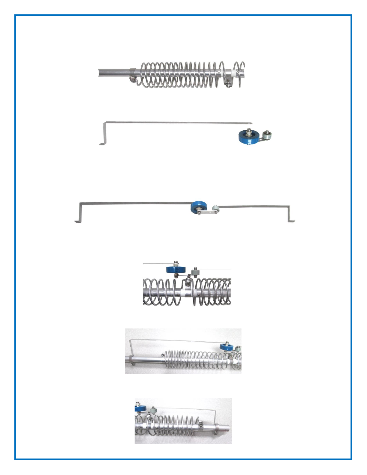
24. Attach the 17M strip (X) to the bolt that fastens the coil to the plastic insulator between the coil
and the upper clamp of the 17M coil assembly A-17-12 (W). Use the attached flat washer, lock
washer and hex nut.
25. Attach the 12M strip (Z) to the 12M coil
assembly A-17-12 (Y). Use the attached flat
washer, lock washer and hex nut.
26. Loosen the #10 hex nut on the bottom clamp
and the wing nut on the upper clamp of the
17M coil assembly A-17-12 (W) and slide the
assembly over the upper end of tube (E) with
the insulator end up.
27. Slide the unit down until the lower clamp of
the 17M coil assembly A-17-12 (W) rests on
the upper clamp of the coil/capacitor
assembly 30 meter (O).
28. Tighten the hex nut and stretch the coil so
that the distance between the upper edge of
the lower clamp and the lower edge of the
upper clamp is 10-1/2”.
29. Install the 12M coil assembly A-17-12 (Y) in
the same way, so the lower edge of the lower
clamp is about 2” above the upper clamp of
the 17M coil assembly A-17-12 (W). This
distance is not critical. Note: The 12M coil
MUST be compressed as much as possible
upon initial tuning. If not, it is highly
probably that 12M will actually be tuned into
10M throwing the ability to tune 10M at all.
30. Tighten the hex nut and stretch the coil so that the distance between the upper edge of the lower
clamp and the lower edge of the upper clamp is 8-3/4”.
Page 14

- 13 -
Steps 31 through 48 are for installing the 15 and 6 meter parts to the antenna. Use the following
diagram to assist in identifying the parts and their proper locations. On tubes E, F and G, the
hole that is drilled 5/8” from the end goes toward the top of the antenna.
31. Position wire clamp 0.875" 15M with insulator (K) around tube (F) and use a # 8 x 1" screw,
lock washer and hex nut. Tighten just finger tight. Final adjustment will be done in a later step.
32. Slide wire clamp 0.875" 6M with insulator (V) around tube (F).
33. Insert the end of tube (G) into the end of tube (F) and secure with a # 8 x 1 1/4" screw, lock
washer and hex nut.
34. Position wire clamp 0.750" 6M with insulator (U) around tube (G).
35. Locate wire clamp 0.750" 15M with insulator (N) and position it around tube (G). Final
tightening and positioning will be done in a later step.
Page 15

- 14 -
36. Insert the end of tube (H) into the end of tube (G) and secure with a # 8 x 1" screw, lock washer
and hex nut.
37. Position wire clamp 0.625" 6M with wire (T) around tube (H) so the top edge is 33-1/4” from
the upper end of the tube.
38. Pass the free end of the stranded wire from wire clamp 0.625" 6M with wire (T) through the
small hole in wire clamp 0.750" 6M with insulator (U).
39. Line up and position the bottom edge of the 6M wire clamp 0.875" with insulator (V) 58" from
the upper edge of the 6M wire clamp 0.625" with wire (T) and tighten.
40. Pass the free end of the stranded wire from the 6M wire clamp 0.625" with wire (T) through the
small hole in the 6M wire clamp 0.875" with insulator (V). Loop the free end of the wire
around itself. Do not cut off the excess.
41. Center and align wire clamp 0.750" with insulator (U) and tighten.
Page 16

- 15 -
42. Locate the 15M wire clamp 0.625" with insulator (M) and position it around tube (H). Final
tightening and positioning will be done in a later step.
43. Insert the end of tube (I) into the end of tube (H) and secure with a # 8 x 1" screw, lock washer
and hex nut.
44. Position wire clamp 0.500" 15M with wire (L) around tube (I) so the top edge is 13-1/2 inches
from the upper end of the tube and on the opposite side from the 6 meter assembly.
45. Measure from the rivet of wire clamp 0.500" 15M with wire (L) to a point 11 feet 3 inches along
the stranded wire and mark this point.
46. Pass the free end of the stranded wire from wire clamp 0.500" 15M with wire (L) through the
small holes in wire clamp 0.625" 15M with insulator (M) and wire clamp 0.750" 15M
w/insulator (N) as shown.
47. Loop the end of the wire through the hole in wire clamp 0.875" 15M with insulator (K) sliding it
on tube (F) until the mark on the wire appears. Wind the wire back on itself. Do not cut off the
excess wire.
Page 17

- 16 -
48. Line up wire clamp 0.875" 15M with insulator (K), wire clamp 0.750" 15M with insulator (N)
and wire clamp 0.625" 15M with insulator (M) with wire clamp 0.500" 15M with wire (L) and
tighten all clamps making sure the wire is moderately taut but not enough to cause the upper
tubing section to bow. Once tuning is complete, cover the end of the 15M and 6M wires with
Scotch® Super 33+ tape to keep water from entering the wire.
49. Slide the uncapped end of tube (J) into the slotted end of tube (I) until 25 inches extends out
from the end of tube (I) and secure with the small adjustable compression clamp (CC).
50. Place the protective cap (AA) on one end of tube (J).
NOTE: In the following steps the antenna will be assembled and raised to its full vertical height. If
the antenna is to be installed in an elevated position where it is unsafe or inconvenient to make
in-place adjustments, the antenna may have to be installed in one piece. It will probably be
necessary to raise and lower it and its supporting structure a number of times to arrive at the
ideal adjustment on all bands. If so, every precaution should be observed in order to avoid
possible contact with power lines and to prevent structural failure that can cause injury to
persons or property.
WARNING: AVOID POWER LINES!
51. Place the lower end of tube (B) through tube (E) over the insulator on tube (A) with insulator.
Line up the holes and secure it with a # 8 x 2" screw, lock washer and hex nut.
52. Raise the assembly of tube (F) through tube (J) and slide the lower end into tube (E) fastening it
securely with a # 8 x 1-1/4" screw, lock washer and hex nut.
Page 18

- 17 -
53. Install the Red Coil (Q) and the Feedpoint Connector (R1) in place as shown below. The Red
Coil and the Feedpoint Connector span over the insulator between Tube (A) and Tube (B). The
Red lead on the Feedpoint Connector connects to Tube (B), the Black lead on the Feedpoint
Connector connects to Tube (A). The 20 meter 75 ohm matching coaxial cable (R) connects to
the Feedpoint Connector (R1). The leads connecting the Feedpoint Connector can be bent to
accommodate your installation requirements. To aid in eliminating water damage of the coax,
weatherproof the coax connector when connected to the Feedpoint Connector.
NOTE: Attach radials and ground to tube with insulator (A) using the remaining # 8 hardware on
the ground side (lower side) of the coaxial cable connection.
WARNING: MAKE SURE THAT THE STATION EQUIPMENT IS CONNECTED TO A
GOOD EARTH GROUND! DO NOT HANDLE CABLE CONNECTED TO STATION
EQUIPMENT WITHOUT FIRST DISCONNECTING THE EQUIPMENT FROM THE
POWER MAINS. YOU COULD BE ELECTROCUTED!
55. Connect the other end of the 75 ohm matching (R) coaxial cable to any
length of 50 to 53 ohm coaxial cable that goes to your transmitter. This
connection should also be weatherproofed
Page 19

- 18 -
Checkout and Adjustment
Adjustments will have to be made before trying to transmit with this antenna system. Installations
vary considerably and there are no ‘set’ measurements that will work for all the variables in the
installation. The dimensions and coil settings that were used during assembly are somewhat close
and may produce reasonably low VSWR readings over the entire 10, 15, 20 and 30 meter bands and
at least 250 kHz of the 40 meter band. Bandwidth on 80/75 meters should be at least 30 kHz for
VSWR of 2:1 or less at the low end of the band and may be as much as 100 kHz at the high end of
the band, depending on the efficiency of the ground system used, greater bandwidth being
associated with lossy ground systems. It should be remembered that on those bands where the
physical height of a vertical antenna is less than 1/4-wavelength, the earth (or the resonant radial
system in above-ground installations) will have a good deal to do with VSWR and antenna tuning,
bandwidth and overall performance.
Low VSWR by itself does not mean that a vertical antenna is operating efficiently, and if low
VSWR is obtained with no more than the usual quick and dirty ground connection, it most likely
means the opposite. In general, poor operation or improper tuning of vertical antennas can usually
be attributed to inadequate (or even reactive) ground systems or to other vertical conductors in the
vicinity of the antenna. For these reasons it is suggested that the antenna be placed as much in the
clear as possible and used with the best ground system that conditions permit. For a more complete
discussion of the interrelationships between vertical antenna efficiency, bandwidth, VSWR, etc., a
standard text such as the A.R.R.L. Antenna Book is recommended.
For adjustment purposes a simple VSWR indicator may be used. More accurate measurements may
be made at the antenna (i.e., at the junction of the coax 75 ohm matching (R) and the main
transmission line) than at the input end of the line, but the tuning conditions that exist at the
transmitter will usually be of greater interest in that one's principal concern will be to couple power
from the transmitter into the transmission line.
1. Check VSWR on 10 meters. To raise the resonant frequency loosen the small clamp over the
slotted end of tube (I) and slide tube (J) farther into tube (I). To lower the frequency, slide tube
(J) farther out of tube (I) and retighten the small clamp. A length change of 3 inches should
move the VSWR curve approximately 200 kHz.
NOTE: you can measure then adjust 15 and 10 meters at the same time since they don’t
interact like other band adjustments. This may help save some time and effort when
tuning. The 12M coil MUST be compressed as much as possible upon initial tuning. If
not, it is highly probable that 12M will actually be tuned into 10M throwing the ability to
tune 10M at all.
2. Check VSWR on 15 meters. The VSWR curve may be shifted upward or downward by
changing the length of the stranded wire between wire clamp 0.500" 15M with wire (L) and
wire clamp 0.875" 15M with insulator (K).
To raise the frequency, simply shorten the wire by wrapping a longer tail back on itself and
sliding the lower clamp upward to maintain tension. To lower frequency, feed more of the tail
back through the hole in the insulator to increase the length of the wire between wire clamp
Page 20

- 19 -
0.500" 15M with wire (L) and wire clamp 0.875" 15M with insulator (K). A change of 2 inches
will shift the VSWR curve approximately 300 kHz.
Check VSWR on 6 meters. To raise the frequency of the lowest VSWR, shorten the length of
the wire and to lower frequency increase the wire length. Alternatively, the upper clamp and the
entire 6 meter assembly may be placed higher on the antenna to lower frequency or lower to
raise it.
Note: 15M and 6M will interact with each other. Changing one band (15M or 6M) will affect
the other band’s tuning. You will have to make adjustments and check both bands until you are
satisfied with the results.
3. Determine the frequency at which VSWR is lowest on 80/75 meters. The coil setting given
earlier should produce resonance and lowest VSWR at approximately 3700 kHz.
To raise the frequency of resonance of the lowest VSWR, simply loosen the wing nut on the
lower coil clamp of the coil assembly 80/40 meter (C) coil on tube (B) and stretch the coil a bit
more. To lower the frequency, compress the coil. A One inch change in the setting of this coil
will produce a frequency shift of approximately 125 kHz.
NOTE: Remember that the antenna tunes very sharply in this range and that high values of VSWR
may be encountered only a few kHz either side of the lowest VSWR readings, so it would be
well to take VSWR readings every 25 kHz or so to avoid running past the frequency of
resonance and lowest VSWR.
NOTE: To minimize interference to other stations and to avoid erroneous reading use only enough
power to produce full-scale deflection of the meter in the forward or R.F. out position.
4. Once the proper coil setting has been found for the desired band segment, coil (Q) base
matching at the base of the antenna may be adjusted for even lower VSWR. If earth losses are
moderate to high a good match may be possible if coil (Q) base matching is left fully
compressed; if earth losses are low (as with an extensive radial system) coil (Q) base matching
may have to be stretched to twice its compressed length or more for a good match. In any case, a
single setting for coil (Q) base matching should suffice for operation over most of 80/75 meters
provided the 80 meter coil is readjusted for each different band segment. Note that coil Q will
have to be cut to remove turns and stretch the coil. The combination of cutting and stretching
should be such to keep the dimensions of the coil reasonable and strong mechanically. Most
installations will have to stretch and remove turns considerably. As you make the adjustments,
check your VSWR, note that you CAN, and should get it down to 1:1.
5. Determine the frequency of minimum VSWR on 40 meters. The coil setting given earlier should
produce resonance and lowest VSWR at approximately 7150 kHz. The 40 meter VSWR and
resonance curve may be shifted in the same manner as on 80/75 meters by changing the setting
of the upper coil clamp of coil assembly 80/40 meter. On this band the setting is much less
critical, and a 1 inch change in the clamp setting will shift the VSWR curve approximately 80
kHz. Be sure to loosen the clamp around tube (E) that supports the 30 meter assembly and to
reposition it as needed to avoid distorting the 40 meter coil.
Page 21

- 20 -
6. Check VSWR on 20 meters. Tuning is quite broad on this band because the antenna is
physically much taller than a 1/4-wavelength.
To raise the frequency of the lowest VSWR, reposition the 30 meter assembly so that the coil
support tube 30 meter L bracket (O1) can be replaced on the next lower turn of the 40 meter
coil. Alternatively, to lower the frequency of lowest SWR, reconnect the coil support tube 30
meter L bracket (O1) to the next higher turn of the 40 meter coil.
In some cases moving the tap point a full turn up or down may cause more of a frequency shift
than is desired, in which case the entire 30 meter assembly may be rotated around tube (E) to
permit adjustments of less than one full turn.
7. Check VSWR on 30 meters. To raise frequency, loosen the wing nut on the bottom coil clamp
of coil/capacitor assembly 30 meter (P), stretch the coil and retighten the wing nut.
To lower frequency, compress the coil.
A change of only 1/4 inch will shift the VSWR curve approximately 100 kHz. Large changes in
the setting of coil/capacitor assembly 30 meter (P) may affect 20 and 40 meter tuning, in which
case it may be necessary to repeat steps 5 and 6. In general, the point at which the 30 meter coil
taps on to the 40 meter coil will be the major factor in 20 meter tuning.
8. Check VSWR on 17 meters. To move the SWR curve to a higher frequency loosen the wing nut
on the upper coil clamp and STRETCH the coil about 1/16” at a time. To move the SWR curve
to a lower frequency range COMPRESS the coil a like amount. 17M is a bit difficult to tune
perfectly. Make small adjustments. A reading of 2.5:1 on 17 is normal.
9. Check VSWR on 12 meters. Stretch the 12 meter coil in increments of 1/16” or so to raise the
resonant frequency, or compress the coil a like amount to lower the resonant frequency. Note:
The 12M coil MUST be compressed as much as possible upon initial tuning. If not, it is highly
probably that 12M will actually be tuned into 10M throwing the ability to tune 10M at all. 12M
is very sensitive when making adjustments changes of 1/4” can cause your tuning to go out of
band (high or low) - make small 1/16” adjustments.
10. Adjustments for 40, 30, 20, 15, 17, 12, 10 and 6 meters should have little or no effect on the
previous adjustments for 80/75 meters, but a final VSWR check for this band should be made.
In the preceding steps it has been assumed that the antenna has been installed in a more or less clear
spot away from other vertical conductors such as TV antenna feedlines, towers and masts, and that a
minimal ground radial system has been installed.
If those fairly basic conditions have not been met it is likely that resonance and low VSWR will be
impossible on some or even all bands. One should bear in mind that VSWR, even with a resonant
antenna, will depend in large measure on local ground conductivity, the extent of the radial system
used, and on other factors over which the operator may have little or no control. Fortunately, the
evils of VSWR greater than unity have been grossly exaggerated in recent decades, and the only
practical difference between a VSWR of unity and one of, say, 3:1 in the average case lies in the
reluctance of modern equipment to deliver full power into lines operating at the higher VSWR
without the help of a transmatch or other outboard matching device.
Page 22

- 21 -
Transmitters having so-called broadband solid-state output circuits (no tuning or loading controls)
may be especially troublesome in this regard, whereas the older vacuum tube pi-network
transmitters can usually be adjusted for maximum output over a tuning range where the VSWR does
not exceed 2.5:l.
Lightning Protection
Modern solid state amateur equipment is particularly vulnerable to damage from lightning or
static induced transients that may appear on transmission lines. Lightning protection products
should be installed.
Troubleshooting
Check out your installation again, looking for loose connections and checking all dimensions.
Then refer to the list of possible symptoms below:
Symptom: Few or no signals heard: bands seem dead, SWR is very high.
Look for: Open or shorted feedline, open or shorted matching line, broken connection at base of
antenna (feedpoint).
Symptom: High SWR on 20 meter; other bands OK.
Look for: Missing matching line. Antenna not properly tuned. 20 meter radials not present or
wrong length. Consult instructions for tuning and radial information; install matching
line RG-11 75 ohm coax, electrical length to be 1/4-wavelength.
Symptom: High SWR on some bands, but signals heard on all bands (conditions permitting).
Look for: Missing or defective radial system. Install as per instructions and check connections to
radials and ground system. Keep this connection 6 inches or less.
Symptom: SWR on 15 meters seems to vary during a windy day.
Look for: This is normal since the 15 meter wire is side mounted and when the antenna sways,
the distance between the 15 meter wire and main antenna will vary.
Symptom: SWR on 17 meters seems to be high compared to the other bands.
Look for: This is normal. 17 meters has always been difficult to tune. A VSWR of 2.5:1 is
acceptable for 17 meters.
Symptom: Tuning is sharp with narrow bandwidth on 80 meters.
Look for: Normal condition. The total length of the antenna represents such a small percent of a
wavelength on this band that sharp tuning is a normal condition.
Symptom: Antenna was installed on the ground and tuned OK, but tuning changed over a period
of weeks or months.
Look for: Antenna installed over poor ground system. Ground conditions have changed, causing
shift in resonance. Install radial system as per instructions. Check connection to radial
Page 23

- 22 -
system. When you see this problem, you may assume that a ground rod without a
radial system is not enough. Vertical antennas require a good radial wire system.
Symptom: Resonant point changes during wet or icy weather.
Look for: Normal condition.
Symptom: Insulation arcs over between 80 meter and 40 meter coils damaging fiberglass.
Look for: Operation at high power levels in areas where salt or pollution deposits have built up
on the insulators. The cure is to keep insulators clean through routine maintenance.
Symptom: Intermittent operation. SWR jumps up and down suddenly, and reception is also
intermittent.
Look for: Loose connections in the feedline or matching line (if used). Bad relay in rig. Bad
antenna switch or connecting cable. Broken or corroded connections at the feedpoint.
Bad radial/ground connection. Radial or antenna contacting metal when wind blows.
Loose hardware on the antenna. Check and secure all connections.
Symptom: Antenna displays generally degraded performance after long period of time.
Look for: Lack of routine maintenance. Coax may be waterlogged or damaged. Buildup of salt or
pollution deposits on insulators and capacitors. Radial system corroded or rotted away.
Owner must do routine maintenance at intervals, according to local conditions.
Symptom: SWR is OK on 75 meters, but goes up gradually when high power is applied. This is
accompanied by heating of 200 pF capacitor.
Look for: Bad ceramic capacitor. Replace.
Symptom: Antenna doesn't tune 80 meters even though radials are in place and of proper length.
Look for: Antenna far out of tune; operator has not followed systematic tuning procedure. Start
with suggested settings in instructions. Make an SWR chart to determine point of
resonance. Adjust coils carefully! Remember, tuning, is sharp on these bands, so it is
easy to pass the resonant point, then assume erroneously that the antenna isn't tuning.
BEFORE you call Butternut for help, please double check your installation, including
all connections and dimensions. Tune carefully and systematically. Have SWR curves
available. Be prepared to describe your installation in detail.
Page 24

- 23 -
A Few Words About the Capacitors.
The door-knob capacitor used on the Butternut Verticals can be difficult to find. Over the years the
shape and size has changed depending on the source of the capacitors.
Prior to October of 2016 - the following capacitor assemblies were used:
BUT-290-05 BUT-290-06 BUT-290-07
200 pf 67 pf 67 and 200 pf with Bracket
As of October 2016 - the following capacitor assemblies are:
BUT-290-05A BUT-290-06A BUT-290-07A
200 pf 67 pf with Bracket 67 and 200 pf with Bracket
The bracket with the newer capacitors is longer that the older bracket. When upgrading to the newer
capacitors, the user will also have to slightly drill out the holes in parts D1 and D2 to fit the larger
screws used on the newer capacitors.
There is no difference in tuning the antenna with the newer capacitors.
Page 25

- 24 -
Guying the HF9V Antenna
The HF9V is designed to survive winds of up to 80 mph without guying in the absence of ice
loading or heavy precipitation, but over a period of time it is to be expected that frequent or even
constant flexing or vibration will reduce the chances for survival in winds that would not damage a
newly installed antenna. Therefore in areas of frequent or heavy winds a set of short non-conductive
guys should be used to reduce the stresses that wind loading will impart to the lower sections of the
antenna.
It should be noted that light nylon
twine is totally unsuitable as guying
material because it has too much
stretch per unit length, although the
heavier sizes of nylon rope (or even
sash cord) may be suitable if used in
short runs. The guy ropes should not
be tight. They should allow for some
movement of the antenna.
Synthetic Textile Industries Antenna Support Rope which is a premium double-braided
Dacron/Polyester rope has been used for guying vertical antennas. A single set of guys placed just
above the 30 meter circuit will contribute greatly to the stability and the longevity of the antenna,
provided that the guys retain a slight amount of slack and do not come off at too steep an angle.
At angles of less than 45 degrees, the guys begin to exert a downward compressive force on the
structure that can be more of a threat to survival than lateral wind loading on an un-guyed structure.
Under no circumstances should guys be placed higher than one-third of the way up the antenna. The
upper two-thirds of the HF9V has little more than its own weight to support, so these sections may
be allowed to bend with the wind with no serious risk of damage. It is the lower third of the antenna
that must support both the weight of the upper sections and the wind loading on them and are thus
more likely to receive damage in severe winds.
Page 26

- 25 -
Butternut® HF9V Parts List
Ref
Description
Qty Ref
Description
Qty A Tube A with Insulator, 1-1/8” dia x 24” long
1 T Wire Clamp, 5/8” with Wire - 6M
1 B Tube B element, 1-1/8” dia x 48” long
1 U Wire Clamp, 3/4” with Insulator - 6M
B1
Tube B1 with Insulator, 1-1/8” dia x 12” long
1 V Wire Clamp, 7/8” with Insulator - 6M
1 C Coil Assembly - 80/40 meters
1 W Coil Assembly - 17 meters A-17-12
1 D Capacitor Assembly 80/40 meters
1 X Strip, Long - 17 meters
1
D1
Capacitor Bracket, Long, 80 meters
1 Y Coil Assembly - 12 meters A-17-12
1
D2
Capacitor Bracket, Short, 40 meters
1 Z Strip, Short - 12 meters
1 E Tube E, 1” dia x 48” long
1
AA
Vinyl End Cap (Black or Grey)
1 F Tube F, 7/8” dia x 48” long
1
BB
Capacitor Bracket Clamp
2
G
Tube G, 3/4” dia x 48” long
1
CC
Adjustable Element Clamp, Small
1
H
Tube H, 5/8” dia x 48” long
1 # 8-32 X 2” Long, Screw
2 I Tube I, 1/2” dia x 48” long
1 # 8-32 X 1-1/2” Long, Screw
3 J Tube J, 3/8” dia x 36” long
1 # 8-32 X 1-1/4” Long, Screw
3 K Wire Clamp, 7/8” with Insulator - 15 meters
1 # 8-32 X 1” Long, Screw
5 L Wire Clamp, 1/2” with Wire - 15 meters
1 # 8-32 X 3/4” Long, Screw
3 M Wire Clamp, 5/8” with Insulator - 15 meters
1 # 8 Split Lock Washer
18 N Wire Clamp, 3/4” with Insulator - 15 meters
1 # 8-32 Hex Nut
18 O Coil Support Tube with Insulator, 1-1/8” dia x 9” - 30 M
1 # 8 Flat Washer
7
O1
Coil Tube Support “L” Bracket - 30 meters
1 #10-24 X 1” Long, Screw
2
P
Coil/Capacitor Assembly - 30 meters
1 #10 Split Lock Washer
8
Q
Coil Q Base, Matching
1 #10 Flat Washer
8
R
75 ohm Matching Coaxial Cable
1 #10-24 Hex Nut
4
R1
Feedpoint Connector block with Ring Terminals
1 #10-24 Wing Nut
5
Page 27

- 26 -
HF9V Assembly
with Enlarged
Details
[Dimension in inches.
Drawings not to scale.]
- 30 -
Page 28

- 27 -
Technical Support
If you have questions about this product, or if you experience difficulties during the installation,
contact Butternut at (330) 572-3200.
For best service, please take a few minutes to review this manual before you call.
Another great place for information about the classic Butternut® Antennas is
the Butternut® IO Group - https://groups.io/g/butternut
This special interest group is moderated by Scott Myers, AC8DE and contains a treasure trove of
Butternut® antenna information from users around the world.
Warranty
All products manufactured by Butternut® are warranted to be free from defects in material and workmanship
for a period of one (1) year from date of shipment. Butternut
®
’s sole obligation under these warranties shall be
to issue credit, repair or replace any item or part thereof which is proved to be other than as warranted; no
allowance shall be made for any labor charges of Buyer for replacement of parts, adjustment or repairs, or any
other work, unless such charges are authorized in advance by Butternut®. If Butternut® products are claimed
to be defective in material or workmanship, Butternut® shall, upon prompt notice thereof, issue shipping
instructions for return to Butternut® (transportation-charges prepaid by Buyer). Every such claim for breach of
these warranties shall be deemed to be waived by Buyer unless made in writing. The above warranties shall
not extend to any products or parts thereof which have been subjected to any misuse or neglect, damaged by
accident, rendered defective by reason of improper installation, damaged from severe weather including floods,
or abnormal environmental conditions such as prolonged exposure to corrosives or power surges, or by the
performance of repairs or alterations outside of our plant, and shall not apply to any goods or parts thereof
furnished by Buyer or acquired from others at Buyer’s specifications. In addition, Butternut’s warranties do
not extend to other equipment and parts manufactured by others except to the extent of the original
manufacturer’s warranty to Butternut®. The obligations under the foregoing warranties are limited to the
precise terms thereof. These warranties provide exclusive remedies, expressly in lieu of all other remedies
including claims for special or consequential damages. SELLER NEITHER MAKES NOR ASSUMES ANY
OTHER WARRANTY WHATSOEVER, WHETHER EXPRESS, STATUTORY, OR IMPLIED,
INCLUDING WARRANTIES OF MERCHANTABILITY AND FITNESS, AND NO PERSON IS
AUTHORIZED TO ASSUME FOR BUTTERNUT ANY OBLIGATION OR LIABILITY NOT STRICTLY
IN ACCORDANCE WITH THE FOREGOING.
©Butternut 2022
Butternut® is a trademark of PDS Electronics, Inc. No license to use or reproduce any trademarks or other
trademarks is given or implied. All other brands and product names are the trademarks of their respective
owners.
Specifications subject to change without notice.
 Loading...