

Butternut
HF2V 80/40
Dual-Band
Vertical Antenna
BUT-HF2V
BUT-HF2V-INS-Revision 4
© Butternut 2019
1200 Southeast Ave. - Tallmadge, OH 44278 USA
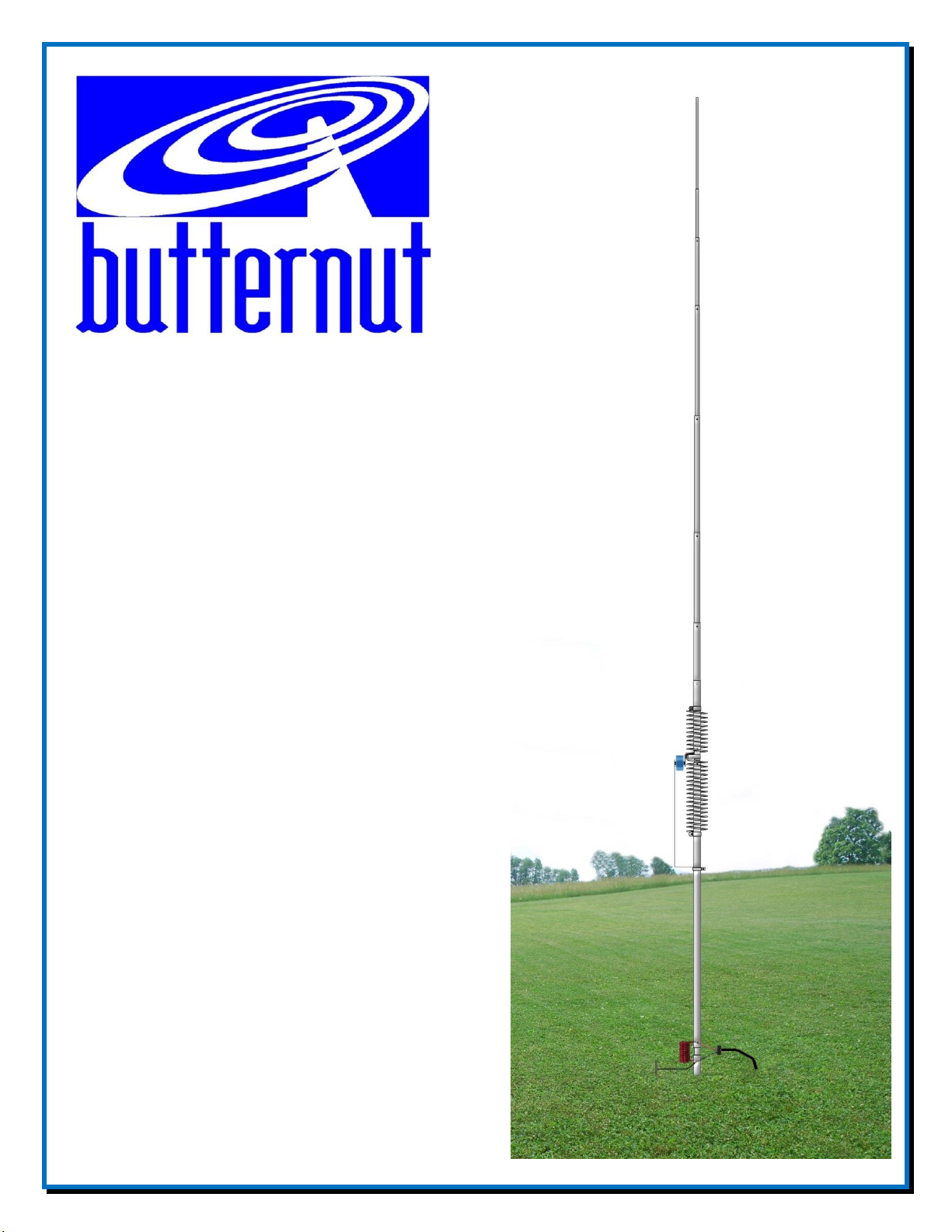
Phone: (800) 777-0703 ∙ Fax: (330) 572-3279 Artists rendition of an installation
Tech Support and International: (330) 572-3200

Introduction
The classic Butternut HF2V vertical antenna operates on 80 and 40 meters. Designed with
corrosion-resistant aluminum tubing, this 32-foot tall antenna is very durable and attractive.
Optimize your performance on 80 & 40 meters.
Features
Band coverage for 80 and 40 meters
Height is 32 feet
Weight is only 13 pounds
Feedpoint Impedance is a nominal 50 ohms and uses a coaxial cable connection at the
antenna base
Power handling up to 1,500 watts - full legal limit on both bands
Will handle 60 mph winds (no ice) - higher winds with guying
Bandwidth for VSWR 2:1 or less: 40 m - entire band. 80 m is 90 kHz
Active element length on 80 & 40 meters is 32 feet
Requires radial system
Please - Read the entire manual to become familiar with the construction of the Butternut HF2V
vertical antenna. This manual does follow the ‘classic’ design and construction methods. However,
throughout the manual information has been added that varies from the ‘classic’ design by adding
newer options that you may want to consider when installing your Butternut HF2V.
WARNING!
INSTALLATION OF ANY ANTENNA NEAR POWER LINES IS DANGEROUS
Warning: Do not locate the antenna near overhead power lines or other electric light or power
circuits, or where it can come into contact with such circuits. When installing the antenna, take
extreme care not to come into contact with such circuits, because they may cause serious injury or
death.
Before you begin working, check carefully for overhead power lines in the area you will be
working. Don't assume that wires are telephone or cable lines; check with your electric utility for
advice. Although overhead power lines may appear to be insulated, often these coverings are
intended only to protect metal wires from weather conditions and may not protect you from electric
shock. Keep your distance! As a suggestion, remember the 10-foot rule; when carrying and using
ladders and other long tools, keep them at least 10 feet away from all overhead lines - including any
lines from the power pole to your home.
There are parts made from fiberglass in this kit. Take normal precautions when handling any
fiberglass material. There may be fiberglass dust, slivers or particles present when the fiberglass
parts were manufactured. The use of typical fiberglass handling safety gear (gloves, dust mask, eye
shield, clothing, etc.) when handling and working with fiberglass is recommended. Use a damp rag
- 1 -

to wipe the parts. Do not use compressed air to clean fiberglass parts. Measures can be taken to
reduce exposure after a person has come in contact with fiberglass. Eyes should be flushed with
water and any area of exposed skin should be washed with soap and warm water to remove fibers.
Clothing worn while working with fiberglass should be removed and washed separately from other
clothing. The washing machine should be rinsed thoroughly after the exposed clothing has been
washed. Check with your local or state safety and/or environmental agencies for more detailed
precautions.
Tools Required
Straight Slot Screwdriver, Phillips Head Screwdriver, 1/4” Nut Driver or socket set,
11/32” Nut Driver or socket set, 3/8” Nut Driver or socket set, Tape measure , Pencil.
Additional Material Needed But Not Supplied
JTL-12555 Jet Lube SS-30 Aniti-Oxidant Corrosion Inhibiting Lubricant
ERO-611360 Ground Rod installed near base of the antenna
DXE-RADW-32RT or 65RT Radial Wires
DXE-RADP-3P Radial Plate
DXE-UHF-FDFB-KIT SecureMount Double SO-39 Connector for the Radial Plate
Guying Kit for Vertical Antennas - Some vertical antenna manufacturers indicate their antennas do
not need guying. During times of high winds or ice loading, some of these vertical antennas may
sustain damage or fail altogether. With the small amount of effort needed to install a four point
guying system, the risk hardly seems worth taking. A four-point guying scheme provides the best
mechanical advantage to reduce wind stress, regardless of direction. Information on guying the
Butternut HF2V is included in this manual.
Site Selection
Ideally, select a mounting location clear from power lines, structures and other antennas by a
minimum of 35 feet. Consider overhead power lines, utility cables and wires. The vertical should
be mounted away from local noise sources or other metallic objects which can re-radiate noise and
affect the tuning, radiation pattern and SWR. Determine the direction you want the antenna to tilt
down and make sure there is adequate clearance (at least 35 feet). There should also be a clear
diameter of 65 to 130 feet from the antenna for the guying and radial systems that will extend away
from the antenna. As with all Amateur Radio antennas there maybe compromises and the ideal site
may not be available.
Radial System
The use of a radial system is a key requirement for any high performance quarter wave vertical
antenna system. With any vertical antenna system, the radials are the second half of the
antenna. The radials contribute to the radiation efficiency of the entire vertical antenna
system.
The exact number of radials required for low SWR and reasonably efficient operation on 80 and 40
- 2 -

meters will depend in large measure on local earth conductivity, and this may vary considerably
from one place to the next and from one frequency band to the next.
The best procedure is to assume that most earth is a poor conductor over the HF range and that
some radial wires will be needed. Radials may be placed on the surface of the earth or buried
slightly below the surface to get them out of the way, and their length is largely a matter of
convenience. In general, a large number of short radials are preferable to a small number of longer
radials for a given amount of wire, especially if fewer than a dozen radials are to be used. Unlike
resonant radials that must be cut to the proper lengths for use with elevated verticals, ground-level
radials need not to be cut to any particular length; their sole purpose is to provide less lossy return
paths for currents flowing along the earth than the earth itself can provide. And, since "return"
currents will be flowing back to the antenna from all points of the compass, the radial wires should
be spaced uniformly over 360 degrees, although physical circumstances will often make this "ideal"
distribution impossible. For a discussion of ground system for elevated verticals, see the section
entitled "Above Ground Installations" following Checkout and Adjustment instructions.
At a minimum, 20 radials, each 32 feet long, may be used with this
antenna. Using 32 radials at 65 feet long is preferred and highly
recommended for the best performance on 80 meters with this antenna.
The extra radials help overcome unknown poor-soil conditions, improve
bandwidth, and ensure the best performance efficiency possible from the
Butternut HF2V antenna. Radial Wire that is 14 gauge stranded copper
with black relaxed PVC insulation wire is suggested for the best results.
DXE-RADW-32RT or 65RT Radial Wire Kits.
The wire radials should be placed as symmetrically as possible straight
from the feedpoint around the vertical antenna and spaced evenly, regardless of how many radials
are used. Do not cross or bunch any radial wires as this nullifies their effectiveness. If you have
limited space, put in as many straight radials as you can. The radials must be connected to the shield
of your feedline. A Radial Plate is the ideal optional item which provides an excellent system for
attaching radial wires to your vertical antenna system.
Radial wires can be laid on the roots of the grass or on bare ground using Radial Wire Anchor Pins
to hold them down. Using enough staples will ensure the wires will not be snagged by mowers,
people, or animals. Depending on where you live and the type of grass you have, grass will quickly
overgrow the radials and it will be virtually impossible to see them. Radials can also be buried just
under the surface (approximately 1” - anything deeper and you will start losing effectiveness) by
using a power edger to make a slit in the soil.
NOTE: The function of a ground rod is to place the antenna at D.C. ground potential. It cannot
take the place of an effective RF ground system, such as a number of radial wires, regardless of its
depth in the earth. It does, however, serve as a convenient tie-point for such radials, as does the bolt
through mounting post w/insulator (A) to which radials can be connected by means of the remaining
#8 hardware.
- 3 -

The Optional Radial Plate
Caution
Aluminum tubing edges can be very sharp.
Take precautions to ensure you do not get accidentally cut.
A DXE-RADP-3 Radial Plate is an ideal option for the radial system that is needed for the
Butternut HF2V vertical antenna. The radial plate can be
set on the ground, or connected by means of a clamp to
the lower tube of the HF2V.
In either case, a ground wire attachment from the lower
tube to the Radial Plate should be made to ensure a good
RF connection. One benefit of the Radial Plate is an
optional double female connector that can be installed
ensuring that the radial field is tied to the antenna system.
Radial Plate shown installed.
Aluminum Tubing Information
When assembling any telescoping aluminum tubing sections you should take the following steps.
1. Make sure the edges are smooth and not sharp. Deburring may be necessary, since burrs and shavings
can occur on seams as well as edges. All surfaces need to be completely smooth to allow easy assembly
of tubing sections.
The raised particles and shavings that appear when the aluminum tubing is machined are referred to as
burrs, and the process by which they are removed is known as deburring.
The aluminum tubing is machine cut on both ends and machine slit on one end. You should further
assure that there are no ragged edges or protrusions.
2. Clean the inside of the aluminum tubing to clear out any dirt or foreign material that would cause the
aluminum tubing sections to bind during assembly. Do not use any type of oil or general lubricant
between the aluminum tubing sections. Oils or general lubricants can cause poor electrical connections
for radio frequencies.
3. Clean the outside of the aluminum tubing to clear any dirt or foreign material that would cause the
clamps to malfunction during assembly.
4. The use of JTL-12555 Jet Lube SS-30 Pure Copper Anti-Seize is highly recommended. Jet Lube is an
electrical joint compound which effects a substantial electrical connection between metal parts such as
telescoping aluminum tubing or other antenna pieces. Using Jet Lube assures high conductivity at all
voltage levels by displacing moisture and preventing corrosion or oxidation.
5. When assembling the aluminum tubing sections, ensure the area is clear of grass, dirt or other foreign
material that could cause problems during assembly of the closely fitted telescoping sections.
- 4 -
 Loading...