

Model BUT-A-6
For the HF6V and HF9V
NOTE: Please read all instructions thoroughly before proceeding to installation and assembly. During
assembly and installation take extreme care to avoid contacting power lines with any part of the antenna
or other conductors.
ASSEMBLY
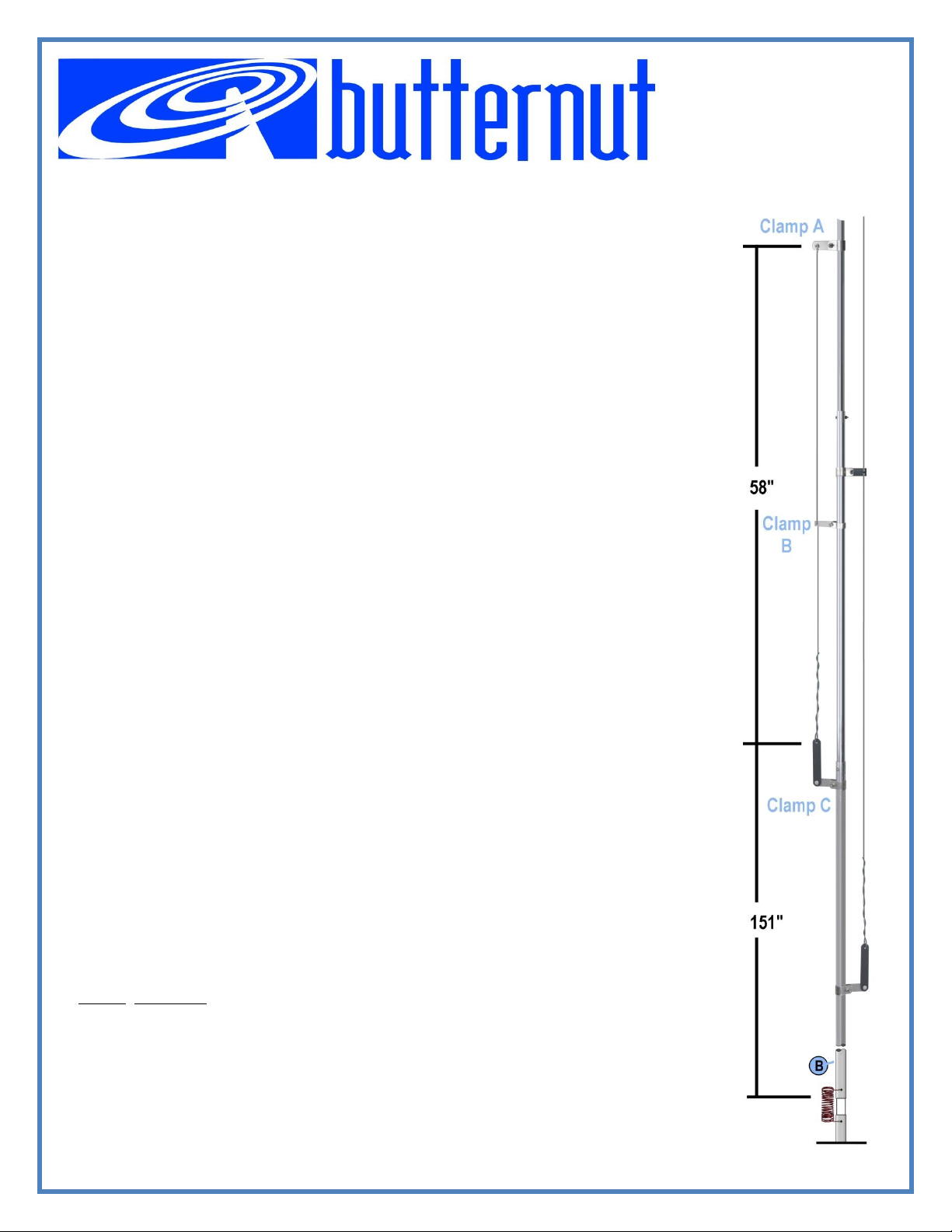
Fasten the upper clamp and attached wire (A) to the antenna 209
1.
bottom
2. Place clamp with the long insulator 58 inches (147 cm) down from clamp
Position the center clamp
3.
NOTE: All clamps for the 6 meter stub should be on the opposite side of the 15 meter
Bring the free end of the wire down through the hole in the plastic part
4.
and on through the hole in the plastic of the
wire back on
THEORY OF OPERATION
The vertical wire from the upper clamp together with the adjacent section of the antenna form a shortcircuited quarter-wave transmission line which cancels current flow. At the lower (open) end of this
quarter-wave section, a very high impedance is created that effectively divorces the upper part of the
antenna on six meters leaving only the lower section to radiate as a 3/4-wave monopole. Why 3/4-wave
rather than 1/4-wave? Because the vertical plane pattern of the former breaks into two lobes, one at zero
degrees and the other at 40 degrees, thus affording both low-angle and skywave propagation. Further,
the radiation resistance of a 3/4-wave radiator is almost twice that of a 1/4-wave radiator, so for a given
earth loss resistance the taller antenna should be more efficient, particularly when operated at ground
level.
Adjustment for resonance or lowest SWR at a particular frequency may be made by adjusting the length
of the wire or in the placement of the upper clamp along the antenna. In general, the wire may be
lengthened to lower resonance or shortened a slight amount to raise it. Alternatively, the upper clamp
(and the entire 6 meter assembly) may be placed higher on the antenna to lower resonance or slightly
lower to raise resonance.
If the antenna is to be mounted more than a foot or so above the earth, several resonant radials may be
required for low SWR operation on 6 meters.
Parts List
Part No Description
Upper Clamp with Attached Wire
Middle Clamp with Short Insulator
Lower Clamp with Long Insulator
of the (B) tube at the base of the
itself.
halfway
between the upper and lower clamps
antenna.
lower
clamp.
inches
(531 cm) up from the
(A) (Hole to hole).
.
stub.
of
the middle clamp
Do not cut the wire, wrap the excess
Instructions
BUT-A-6 Rev 0 - Page 1 of 1
Butternut® - 1200 Southeast Ave. - Tallmadge, OH 44278 USA - Phone: 330-572-3200
 Loading...