

Page 1
USER MANUAL
ProDAQ LXI Instruments
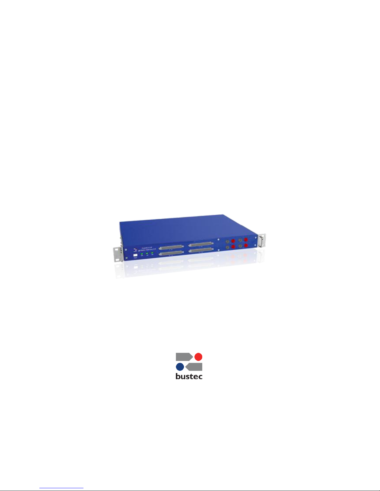
ProDAQ 6140
LXI Matrix Switching Unit
PUBLICATION NUMBER: 6140-XX-UM-1000
Copyright, © 2017, Bustec Production, Ltd.
Bustec Production, Ltd.
Bustec House, Shannon Business Park, Shannon, Co. Clare, Ireland
Tel: +353 (0) 61 707100, FAX: +353 (0) 61 707106
Page 2

PROPRIETARY NOTICE
This document and the technical data herein disclosed, are proprietary to Bustec
Production Ltd., and shall not, without express written permission of Bustec
Production Ltd, be used, in whole or in part to solicit quotations from a competitive
source or used for manufacture by anyone other than Bustec Production Ltd. The
information herein has been developed at private expense, and may only be used for
operation and maintenance reference purposes or for purposes of engineering
evaluation and incorporation into technical specifications and other documents,
which specify procurement of products from Bustec Production Ltd.. This document
is subject to change without further notification. Bustec Production Ltd. Reserve the
right to change both the hardware and software described herein.
Page 3

ProDAQ 6140 LXI Matrix Switching Unit User Manual
Page 1 of 56 Copyright © 2017, Bustec Production Ltd.
Table of Contents
1. Introduction .................................................................................................................. 7
1.1. Overview .......................................................................................................................... 7
1.2. Theory of Operation ........................................................................................................ 8
1.3. Applications ..................................................................................................................... 8
1.4. Monitoring ................................ ................................................................ ........................ 8
1.5. Calibration ........................................................................................................................ 9
1.6. Fault Insertion ................................................................................................................ 10
2. Specifications ............................................................................................................. 11
2.1. Available Versions ......................................................................................................... 11
2.2. General ........................................................................................................................... 11
2.3. Relay Ratings ................................................................................................................. 11
2.4. Signal Connectors ......................................................................................................... 11
2.5. Network Interface .......................................................................................................... 11
2.6. LXI Device Capabilities ................................................................................................. 11
2.7. Environmental Specifications ....................................................................................... 12
2.8. Power Supply ................................................................................................................. 12
3. Getting Started ........................................................................................................... 13
3.1. Unpacking and Inspection ............................................................................................ 13
3.2. Front Panel ..................................................................................................................... 13
3.2.1. Switches and Indicators ............................................................................................ 13
3.2.2. Connectors ............................................................................................................... 14
3.3. Rear Panel Connectors ................................................................................................. 14
3.4. Mounting the ProDAQ 6140 in a 19” Rack ................................................................... 15
3.5. Device Discovery ........................................................................................................... 15
3.5.1. Accessing the ProDAQ 6140 using Multicast DNS ................................................... 15
3.5.2. Discovering the ProDAQ 6140 using VXI-11 Broadcast............................................ 16
4. Web Page Operation .................................................................................................. 17
4.1. Instrument Home Page .................................................................................................. 17
4.2. IP Configuration ............................................................................................................. 18
4.3. Relay Configuration ....................................................................................................... 20
4.3.1. Relay Operation ........................................................................................................ 21
4.3.2. Aliases ...................................................................................................................... 23
4.3.3. Presets ..................................................................................................................... 24
4.4. Device Status ................................................................................................................. 26
4.5. Advanced Status ............................................................................................................ 26
4.6. System Log .................................................................................................................... 27
4.7. Device Configuration ..................................................................................................... 28
Page 4

User Manual ProDAQ 6140 LXI Matrix Switching Unit
Copyright © 2017, Bustec Production Ltd. Page 2 of 56
4.7.1. General Settings ....................................................................................................... 28
4.7.2. Fan Settings ............................................................................................................. 29
4.7.3. Security Settings ....................................................................................................... 29
4.7.4. Firmware Update ...................................................................................................... 30
4.8. Datasheet and Manual Pages ....................................................................................... 31
5. Software Driver .......................................................................................................... 33
5.1. Installation ..................................................................................................................... 33
5.2. Soft Front Panel ............................................................................................................. 33
5.2.1. Starting the Soft Front Panel .................................................................................... 33
5.2.2. Operating the Soft Front Panel ................................................................................. 35
5.3. Using the VXIplug&play Driver ..................................................................................... 42
5.3.1. Connecting to the device .......................................................................................... 42
5.3.2. Operating Relays ...................................................................................................... 43
5.3.3. Using the internal Voltage Reference ....................................................................... 46
5.3.4. Storing and retrieving Aliases ................................................................................... 47
5.3.5. Managing Presets ..................................................................................................... 48
6. Connector Pin-outs .................................................................................................... 49
6.1. Signal channels X1 - X96 (200-pin Molex LFH connector) .......................................... 49
6.2. Signal channels X97 - X192 (200-pin Molex LFH connector) ...................................... 50
6.3. Signal channels Y1 - Y96 (200-pin Molex LFH connector) .......................................... 51
6.4. Signal channels Y97 - Y192 (200-pin Molex LFH connector) ...................................... 52
6.5. Rear Bus Daisy-Chaining .............................................................................................. 53
Page 5

ProDAQ 6140 LXI Matrix Switching Unit User Manual
Page 3 of 56 Copyright © 2017, Bustec Production Ltd.
Table of Figures
Figure 1 - ProDAQ 6140 LXI Matrix Switching Unit usage _______________________________ 7
Figure 2 - ProDAQ 6140-AA Front Panel ___________________________________________ 13
Figure 3 - ProDAQ 6140-AB Front Panel ___________________________________________ 13
Figure 4 - ProDAQ 6140 Rear Panel _______________________________________________ 14
Figure 7 - Bustec VISA Agent Popup-menu showing LXI Devices ________________________ 15
Figure 8 - ProDAQ 6140 discovered using the VISA Configuration Utility __________________ 16
Figure 9 - Instrument Home Page _________________________________________________ 17
Figure 10 - IP Configuration Page _________________________________________________ 18
Figure 11 - Relay Configuration Page ______________________________________________ 20
Figure 12 - Single relay operation _________________________________________________ 21
Figure 13 - Toggling several relay states ____________________________________________ 21
Figure 14 - Applying the changes _________________________________________________ 22
Figure 15 - Open/Close Relays Tab _______________________________________________ 22
Figure 16 - Using a list expression ________________________________________________ 23
Figure 17 - Selecting a Channel Name (Alias) Field for Editing __________________________ 24
Figure 18 - Editing the Channel Name (Alias) for Channel X2 ___________________________ 24
Figure 19 - Aliases Tab _________________________________________________________ 24
Figure 20 - Presets Tab _________________________________________________________ 24
Figure 21 - Preset Name Display __________________________________________________ 25
Figure 22 - “preset not saved” Warning _____________________________________________ 25
Figure 23 - Manage Presets Dialog ________________________________________________ 25
Figure 24 - Device Status Page ___________________________________________________ 26
Figure 25 - Advanced Status Page ________________________________________________ 26
Figure 26 - System Log Page ____________________________________________________ 27
Figure 27 - Device Configuration Page _____________________________________________ 28
Figure 28 - General Settings Page ________________________________________________ 28
Figure 29 - Fan Settings Page ____________________________________________________ 29
Figure 30 - Security Settings Page ________________________________________________ 30
Figure 31 - Firmware Update Page ________________________________________________ 30
Figure 32 - Firmware Update Progress _____________________________________________ 31
Figure 33 - Example Installation Dialog _____________________________________________ 33
Figure 34 - Selecting the Connection Method ________________________________________ 34
Figure 35 - Specifying the Instrument Address _______________________________________ 34
Figure 36 - Demo Mode Model Selection ___________________________________________ 35
Figure 37 -Soft Front Panel Application User Interface _________________________________ 36
Figure 38 - Switching a Relay to its “Closed” State ____________________________________ 36
Figure 39 - Relays X3, X4, Y3 and Y4 are toggled, but not switched on the ProDAQ 6140 ____ 37
Figure 40 - After Apply Button was pressed _________________________________________ 37
Figure 41 - Relay Context Menus _________________________________________________ 38
Figure 42 - Using a List Expression ________________________________________________ 38
Figure 43 - Selecting a Channel Name (Alias) Field for Editing __________________________ 39
Figure 44 - Editing the Alias for Channel X1 _________________________________________ 39
Figure 45 - Alias Context Menu Example ___________________________________________ 39
Figure 46 - Save Preset Dialog ___________________________________________________ 40
Figure 47 - Load Preset Dialog ___________________________________________________ 40
Figure 48 - Preset Name Display __________________________________________________ 40
Figure 49 - “preset not saved” Warning _____________________________________________ 41
Figure 50 - Manage Presets Dialog ________________________________________________ 41
Figure 51 - Connecting to the ProDAQ 6140 _________________________________________ 42
Figure 52 - Operating a Relay ____________________________________________________ 43
Figure 53 - Switching multiple Relays ______________________________________________ 45
Figure 54 - Setting the State of all Relays __________________________________________ 46
Figure 55 - Using the internal Voltage Reference _____________________________________ 47
Page 6

User Manual ProDAQ 6140 LXI Matrix Switching Unit
Copyright © 2017, Bustec Production Ltd. Page 4 of 56
Figure 56 - Setting an Alias ______________________________________________________ 48
Figure 57 - “X”/”Y” Signal Connectors Pin Number Assignment __________________________ 49
Figure 6-58 Rear panel view of Bus Daisy Chain connector _____________________________ 53
Page 7
ProDAQ 6140 LXI Matrix Switching Unit User Manual
Page 5 of 56 Copyright © 2017, Bustec Production Ltd.
Reference Documents
Title
Number
Bustec VISA Library and Tools
8200-XX-UM
ProDAQ 3202 Voltage Reference Datasheet
3202-XX-DS
Glossary
DAC
-
Digital-to-Analog Converter
FIFO
-
First-in First-out Memory
Sample
-
16-bit number representing an analog value
Motherboard
-
ProDAQ Motherboard or Carrier featuring function card slots to
install ProDAQ function cards in
Safety
This equipment contains voltage hazardous to human life and safety
and is able to inflict personal injury. Disconnect the device from the AC
line (mains) before opening the covers as described in chapter 3.4.
To operate this device, use a three-conductor power cord and an
power outlet providing protective earth. Do not use a two-conductor
extension cord or a three-prong/two-prong adapter.
If you replace the power cord provided, make sure that the
replacement is rated for the power consumption stated in the
specifications.
Do not position the device so that it is difficult to operate the
disconnecting device.
If the equipment is used in a manner not specified by the
manufacturer, its safety may be impaired.
Waste Electrical and Electronic Equipment (WEEE)
This product complies with the WEEE Directive 2002/96/EC marking
requirement. The affixed product label indicates that you must not
discard this electrical product in domestic household waste.
Product Category: Monitoring and Control Instrumentation
To return unwanted products, contact Bustec Ltd.
!
!
Page 8

User Manual ProDAQ 6140 LXI Matrix Switching Unit
Copyright © 2017, Bustec Production Ltd. Page 6 of 56
(This page was intentionally left blank.)
Page 9
ProDAQ 6140 LXI Matrix Switching Unit User Manual
Page 7 of 56 Copyright © 2017, Bustec Production Ltd.
1. Introduction
1.1. Overview
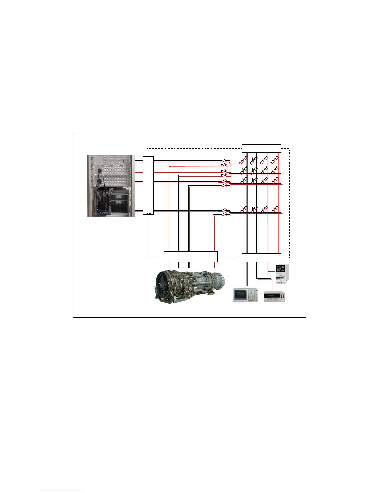
The ProDAQ 6140 provides a relay matrix which can be fitted between the sensors and actuators
on a device under test and the data acquisition and control system. It allows to separately
connect/disconnect the signals from either side and concurrently to connect them to an internal
bus. In this way signals can be routed via the bus to new destinations or the bus can be used to
monitor or supply test signals. This allows calibrating and debugging the system without
disconnecting and separating channels throughout the system wiring.
Figure 1 - ProDAQ 6140 LXI Matrix Switching Unit usage
All relays are latching DPST type relays which keep their set connection even during power off. For
the DAQ/DUT signals high-density connectors with Low Force Helix contacts are used. Test
signals can be accessed via standard 4mm banana-style sockets on the front panel. For scalability,
the bus signals can be daisy-chained to additional ProDAQ 6140 units via D-Sub connectors on the
rear panel.
The ProDAQ 3202 Voltage Reference plug-in can be installed in the unit and can be connected to
either one of the four bus lines.
The ProDAQ 6140 LXI Matrix Switching Unit is a fully compliant LXI device supporting all LXI core
functions via a Gigabit LAN interface.
ProDAQ 6140 Matrix Switching Unit
Bus Daisy Chaining
X
1
X2
X3
Y
1
Y
2
Y
3
Y
192
A B C D
Data Acquisition and
Control System
Page 10
User Manual ProDAQ 6140 LXI Matrix Switching Unit
Copyright © 2017, Bustec Production Ltd. Page 8 of 56
1.2. Theory of Operation
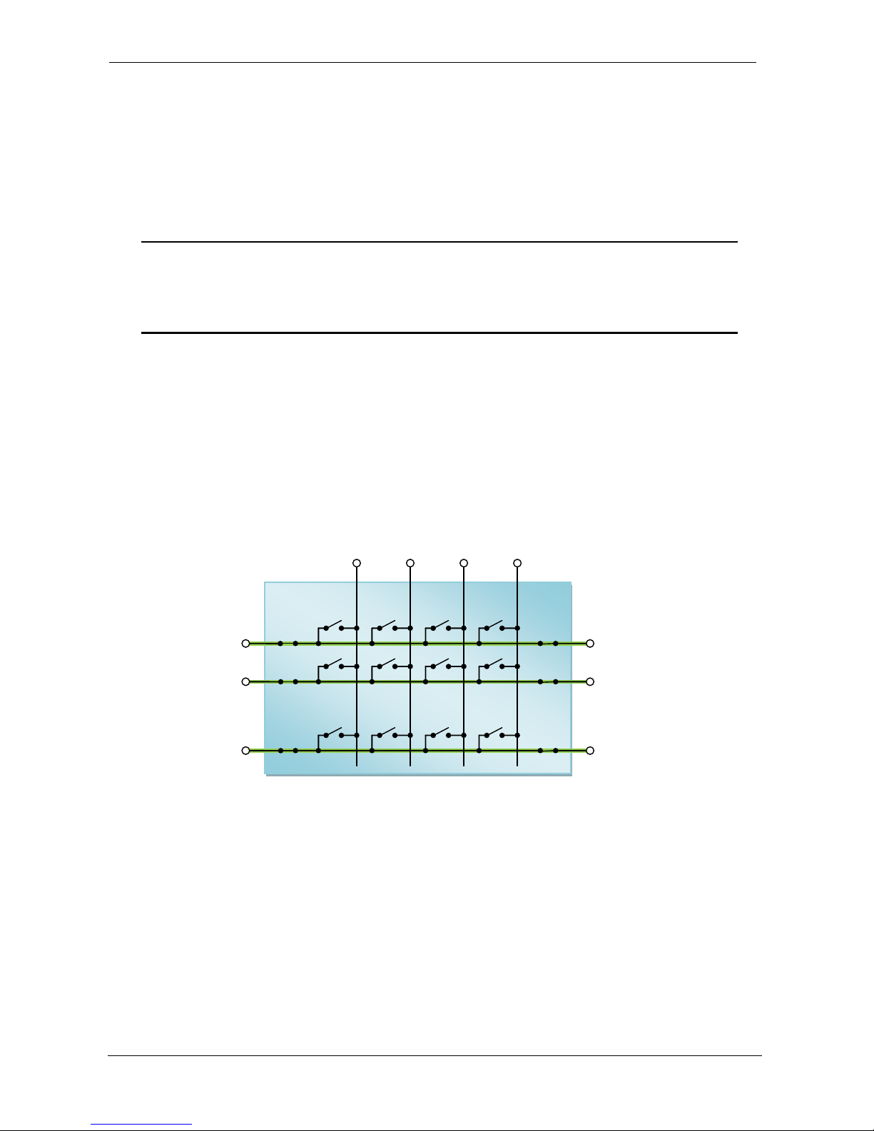
The ProDAQ 6140 LXI Matrix Switching unit uses latching relays to maintain the set connections
between the channels I/Os and bus lines even if it is not powered on. The relays itself do not allow
the firmware and driver(s) to read back their actual state (open/closed). Instead the device starts to
operate from a known state, the default setting (all relays open), and records all operations in an
on-board EEPROM.
NOTE
To maintain relays states over power cycling (on/off), the ProDAQ 6140 does not
reset the relays when powered on. To reset all relays, for example to use it in a new
application, the driver functions must be used.
When writing application software, one must be aware of this fact as well. If the relay states shall
be maintained, the application software must connect to the device without issuing a reset (see…).
1.3. Applications
Located between a data acquisition and control system and the device under test (DUT), the
ProDAQ 6140 LXI Matrix Switching Unit can be used for a variety of applications. In its default
mode, the unit simply connects all channels of the data acquisition and control system to the
sensors and actuators located at the device under test:
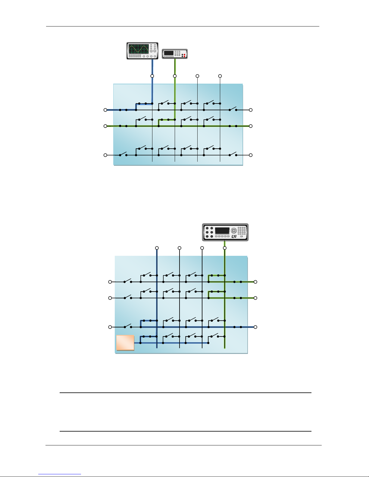
1.4. Monitoring
Signals generated by a sensor on the DUT or by a signal source in the DAQC system can be
monitored by switching the signal on one of the four bussed lines and connecting a scope or a
DMM to its connectors on the front panel. This can be done in parallel to the actual use of the
signal in the DUT and the DAQC system or the connection can be opened on one side to check the
signal without the influence of the other side.
ProDAQ
6140
Device-under-Test
S/A
S/A
S/A
Data Acquistion and
Control System
CH
CH
CH
Page 11
ProDAQ 6140 LXI Matrix Switching Unit User Manual
Page 9 of 56 Copyright © 2017, Bustec Production Ltd.
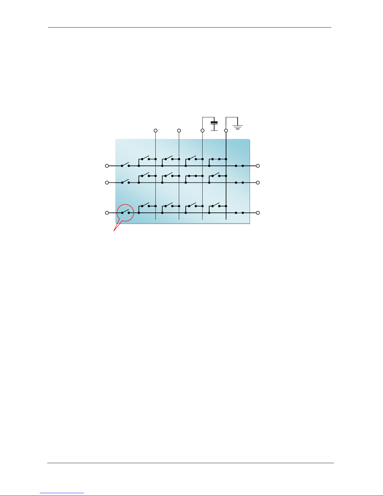
1.5. Calibration
A high-precision signal source (calibrator) connected to one of the bussed lines can be used to
calibrate the channels of the data acquisition and control system without physically connecting or
disconnecting any cables. Using a programmable unit with for example LXI interface allows doing a
complete system calibration in a short time.
When the optional ProDAQ 3202 Voltage Reference is installed in the ProDAQ 6140, highly stable
voltages between 4.5mV and 9V can be internally routed onto any of the four bus lines.
NOTE
The ProDAQ 3202 can only be installed in the factory. If your application wants to
make use of it, you need to order it together with the ProDAQ 6140 initially or send
the ProDAQ 6140 back for the installation.
Device-under-Test
Data Acquistion and
Control System
ProDAQ
6140
S/A
S/A
S/A CH
CH
CH
ProDAQ
6140
Device-under-Test
S/A
S/A
S/A
Data Acquistion and
Control System
CH
CH
CH
3202
VRef
Page 12
User Manual ProDAQ 6140 LXI Matrix Switching Unit
Copyright © 2017, Bustec Production Ltd. Page 10 of 56
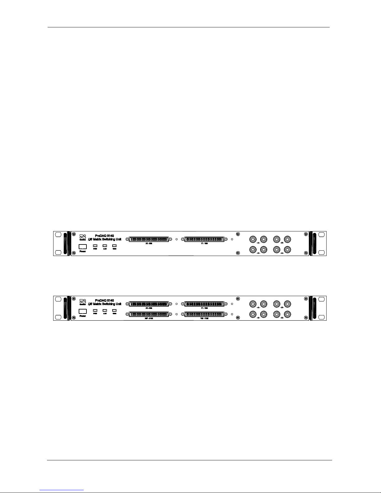
1.6. Fault Insertion
The ProDAQ 6140 can be used to create a number of hardware fault conditions commonly used in
hardware fault insertion testing for mission critical systems where such fault conditions must lead to
a known, deterministic response. Simply by opening one of the “X” or “Y” relays will simulate a
broken wire condition, whereas the bussed lines again can be used to short channels to ground,
against each other or to a certain potential.
ProDAQ
6140
Device-under-Test
S/A
S/A
S/A
Data Acquistion and
Control System
CH
CH
CH
“Broken Wire“
“Short to Battery”
“Short to Ground”
Page 13

ProDAQ 6140 LXI Matrix Switching Unit User Manual
Page 11 of 56 Copyright © 2017, Bustec Production Ltd.
2. Specifications
2.1. Available Versions
Versions
6140-AA LXI Matrix Switching Unit for 96 signal
channels and 4 bussed channels
6140-AB LXI Matrix Switching Unit for 192 signal
channels and 4 bussed channels
2.2. General
Number of signal channels
96 or 192 (“X” - “Y”)
Number of bussed channels
4 (“A”/”B”/”C”/”D”)
2.3. Relay Ratings
Signal Levels
60W (max. 1A and/or 100V)
Relay Type
Electro-mechanical, Latching DPST
Contact Type
PdRu +AU, covered
Electrical Endurance
min. 500,000 operations @ 30VDC/1A
Mechanical Endurance
10,000,000 operations
2.4. Signal Connectors
Signal Connectors (X / Y)
Molex LFH 200-pin
Bussed Signal I/O
4mm Banana Sockets
Bus Daisy-chanining
D-Sub (on rear)
2.5. Network Interface
Type
10/100/1000 Base-T (IEEE 802.3 compliant)
Auto-MDIX
yes
Connector Type
RJ45
Protocols
TCP/IP, HTTP, VXI-11, IEEE1588, mDNS
2.6. LXI Device Capabilities
LXI Class Compliance
LXI Class C
LXI Version
1.3
Programmatic Interface
Embedded Web Interface
VXI-11 Device, Instrument Discovery
IVI/VXIplug&play compatible driver
Page 14

User Manual ProDAQ 6140 LXI Matrix Switching Unit
Copyright © 2017, Bustec Production Ltd. Page 12 of 56
2.7. Environmental Specifications
Temperature
0 °C to +50 °C (operational)
-40 °C to +70 °C (storage only)
Humidity
5% - 95% (non-condensing)
2.8. Power Supply
Input Voltage
85-265 VAC, 47-63 Hz
Current Consumption
1.6 A max.
Fuses
2A Slow-Blow
Page 15
ProDAQ 6140 LXI Matrix Switching Unit User Manual
Page 13 of 56 Copyright © 2017, Bustec Production Ltd.
3. Getting Started
3.1. Unpacking and Inspection
The ProDAQ 6140 is shipped in an antistatic package to prevent any damage from electrostatic
discharge (ESD). Proper ESD handling procedures must always be used when packing, unpacking
or installing any ProDAQ device or ProDAQ function card:
- Ground yourself via a grounding strap or similar, e.g. by holding to a grounded object.
- Discharge the package by touching it to a grounded object, before removing the module from
the package.
- Remove the ProDAQ module from its carton, preserving the factory packaging as much as
possible.
- Inspect the ProDAQ module for any defect or damage. Immediately notify the carrier if any
damage is apparent.
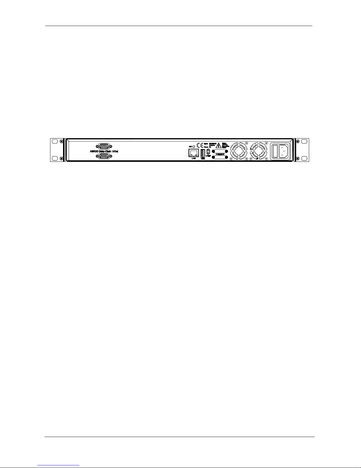
3.2. Front Panel
3.2.1. Switches and Indicators
The ProDAQ 6100 features the following switches and indicators on its front panel:
Figure 2 - ProDAQ 6140-AA Front Panel
Figure 3 - ProDAQ 6140-AB Front Panel
The "Power"- switch connects/disconnects the ProDAQ 6140 from the mains. The "PWR" indicator
shows a constant green light when the ProDAQ 6140 is switched on.
The "LAN" indicator is a bi-color LED. It is used to identify the ProDAQ 6140 via its WEB interface
or its Soft Front Panel and to indicate a LAN failure. When used for LAN identification, it flashes
green, while a LAN failure is indicated by a constant red light. During normal operation, it shows a
constant green light.
The "1588" indicator shows the status of the clock used for the Precision Time Protocol on an LXI
device.
Page 16
User Manual ProDAQ 6140 LXI Matrix Switching Unit
Copyright © 2017, Bustec Production Ltd. Page 14 of 56
3.2.2. Connectors
The ProDAQ 6140 features two (ProDAQ 6140-AA) or four (ProDAQ 6140-AB) LFH connectors to
connect to the “X” and “Y” channels of the relay matrix and four pairs of 4mm banana sockets to
connect to the “A”, ”B”, ”C” and “D” bus lines of the relay matrix.
For pin-outs refer to chapter 6, “Connector Pin-outs”.
3.3. Rear Panel Connectors
The rear panel of the ProDAQ 6140 features the following connectors:
Figure 4 - ProDAQ 6140 Rear Panel
Right to left:
Daisy-Chain In/Out Dual 15-pin D-Sub connectors to connect the “A”/”B”/”C”/”D” bus lines of the
ProDAQ 6140 to the corresponding lines of another ProDAQ 6140.
LAN RJ45 10/100/1000 BASE-TX port with Auto-MDIX
USB USB 2.0 host port
VREF Dual 2mm test socket. When a ProDAQ 3202 Voltage Reference Plug-in
module is installed in the ProDAQ 6140, it can be used to monitor the
voltage reference output.
IEC Inlet Used to connect the ProDAQ 6140 to the mains. It also features the main
fuses.
Page 17
ProDAQ 6140 LXI Matrix Switching Unit User Manual
Page 15 of 56 Copyright © 2017, Bustec Production Ltd.
3.4. Mounting the ProDAQ 6140 in a 19” Rack
The ProDAQ 5725 Rack-mount Kit is available to mount the ProDAQ 6140 into standard 19” racks.
The kit allows mounting the unit into racks with mounting depths between 453 mm and 843 mm.
Please refer to the ProDAQ 5725 assembly instructions for usage.
3.5. Device Discovery
The most convenient way to start accessing a ProDAQ 6140 unit is to use one of the zeroconfiguration networking tools for your host computer that make use of the multicast DNS service
supported by the ProDAQ 6140. With mDNS it is possible to access the device while not knowing
the actual IP address.
3.5.1. Accessing the ProDAQ 6140 using Multicast DNS
Multicast DNS services are provided for Windows by the “Bonjour Print Services” (available at
support.apple.com) and for Linux by Avahi (available at www.avahi.org).
The default mDNS service name for ProDAQ 6140 is:
Bustec Ltd – ProDAQ 6140 – <SERIAL NUMBER>
And the default host name is:
prodaq6140-<SERIAL NUMBER>.local
With the default host name, accessing the web interface is achieved with the following HTTP
address:
http://prodaq6140-<SERIAL NUMBER>.local
When mDNS is used, the resource string for use with the VISA library can have the form:
TCPIP<n>::prodaq6140-<SERIAL NUMBER>.local::INSTR
The host name may be changed by the user, so having an automatic search for mDNS enabled
devices is very useful. The user doesn’t need to know neither the IP address nor the host name of
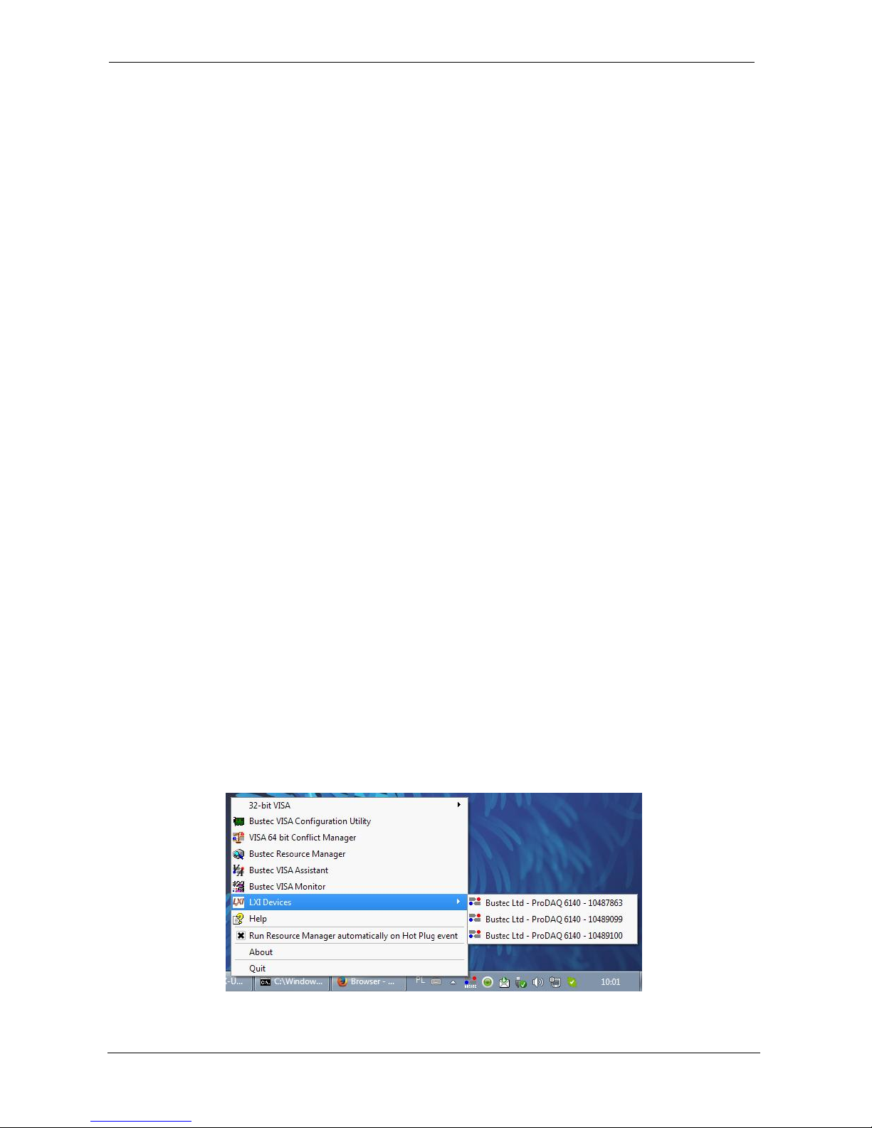
the device. If Bonjour (Windows) or Avahi (Linux) is running on the host, the Bustec Agent tool
installed along with Bustec VISA package makes use of it. It scans for the available devices, lists
them and allows opening their web interfaces. For more information on Bustec VISA please refer to
Bustec VISA Library and Tools User Manual.
Figure 5 - Bustec VISA Agent Popup-menu showing LXI Devices
Page 18
User Manual ProDAQ 6140 LXI Matrix Switching Unit
Copyright © 2017, Bustec Production Ltd. Page 16 of 56
3.5.2. Discovering the ProDAQ 6140 using VXI-11 Broadcast
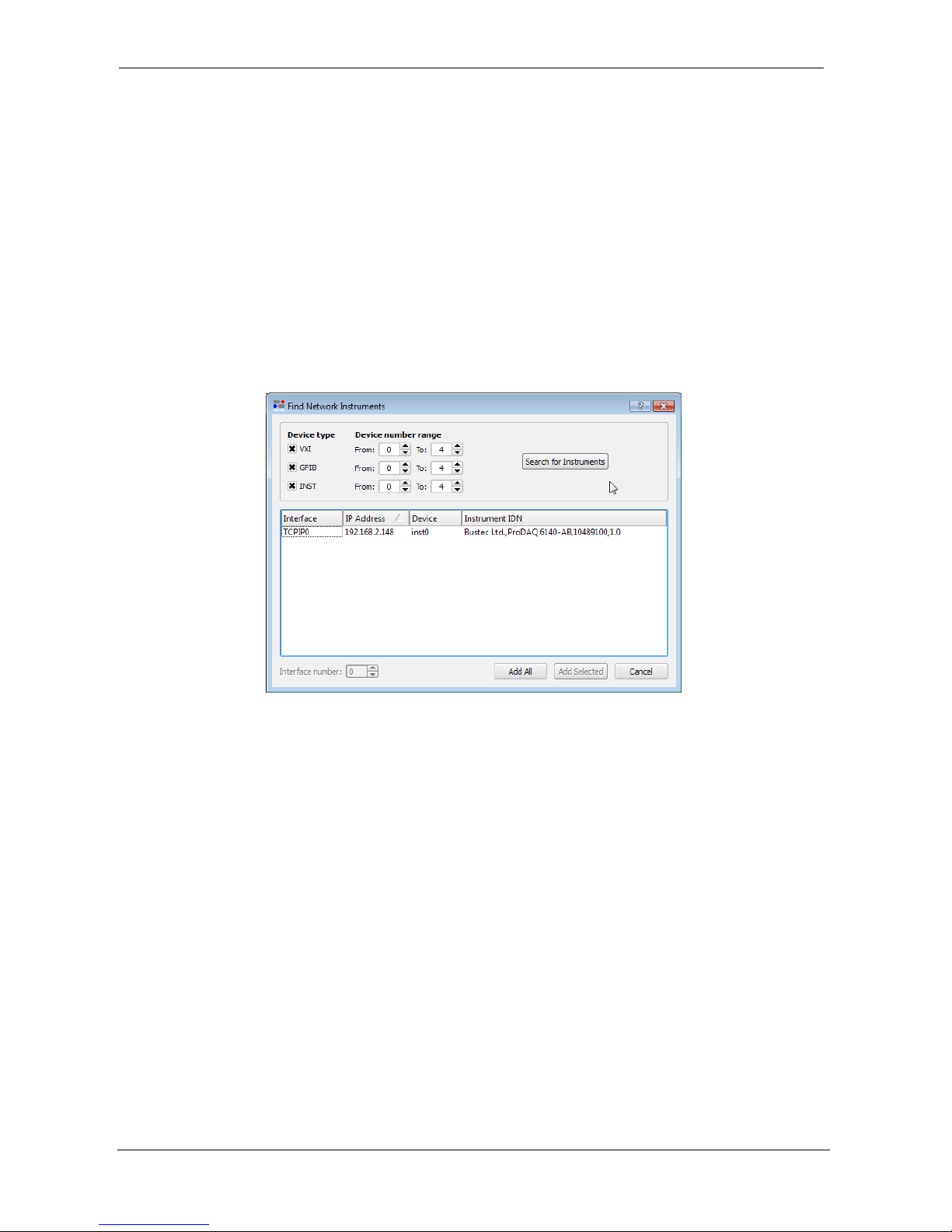
The Bustec VISA Configuration Utility can be used to discover ProDAQ 6140 units by using the
VXI-11 protocol. After starting the configuration utility, select the “Network Instruments” tab and
click on the button “Find Instruments”.
To discover a ProDAQ 6140, the device type “INST” with device number 0 must be included in the
search criteria shown in the “Find Network Instruments” dialog before you click the button “Search
for Instruments”. (By default these criteria are included)
When the search finishes, discovered instruments are shown in the list below. Use the buttons
“Add All” or “Add Selected” to add the instruments to the list of known network instruments. This is
necessary to allow the VISA library and soft front panels to access the devices. For the detailed
description of the procedure please refer to the Bustec VISA Library and Tools User Manual.
Figure 6 - ProDAQ 6140 discovered using the VISA Configuration Utility
The VXI-11 discovery returns the IP address of the devices found, so that the resource string
shown her have the form
TCPIP<n>::<IP Address>::INSTR
Now you can use the embedded web interface or the VISA driver to access, configure and operate
the ProDAQ 6140 LXI Matrix Switching unit.
For a complete description of the embedded web interface, see 4: Web Page Operation. For a
description of the soft front panel coming with the driver see section 5.2: Soft Front Panel.
Page 19
ProDAQ 6140 LXI Matrix Switching Unit User Manual
Page 17 of 56 Copyright © 2017, Bustec Production Ltd.
4. Web Page Operation
The ProDAQ 6140 features an embedded web server, which allows you to configure and operate
the ProDAQ 6140 by using a standard web browser from any host computer in your network. To
make use of the complete functionality of the embedded web interface, the browser will need to
have its JavaScript support enabled.
In order to get access to the instrument’s web interface type its IP address or hostname in the
browser’s address field as described in the previous section or click on automatically discovered
item in the Bustec Agent tool.
4.1. Instrument Home Page
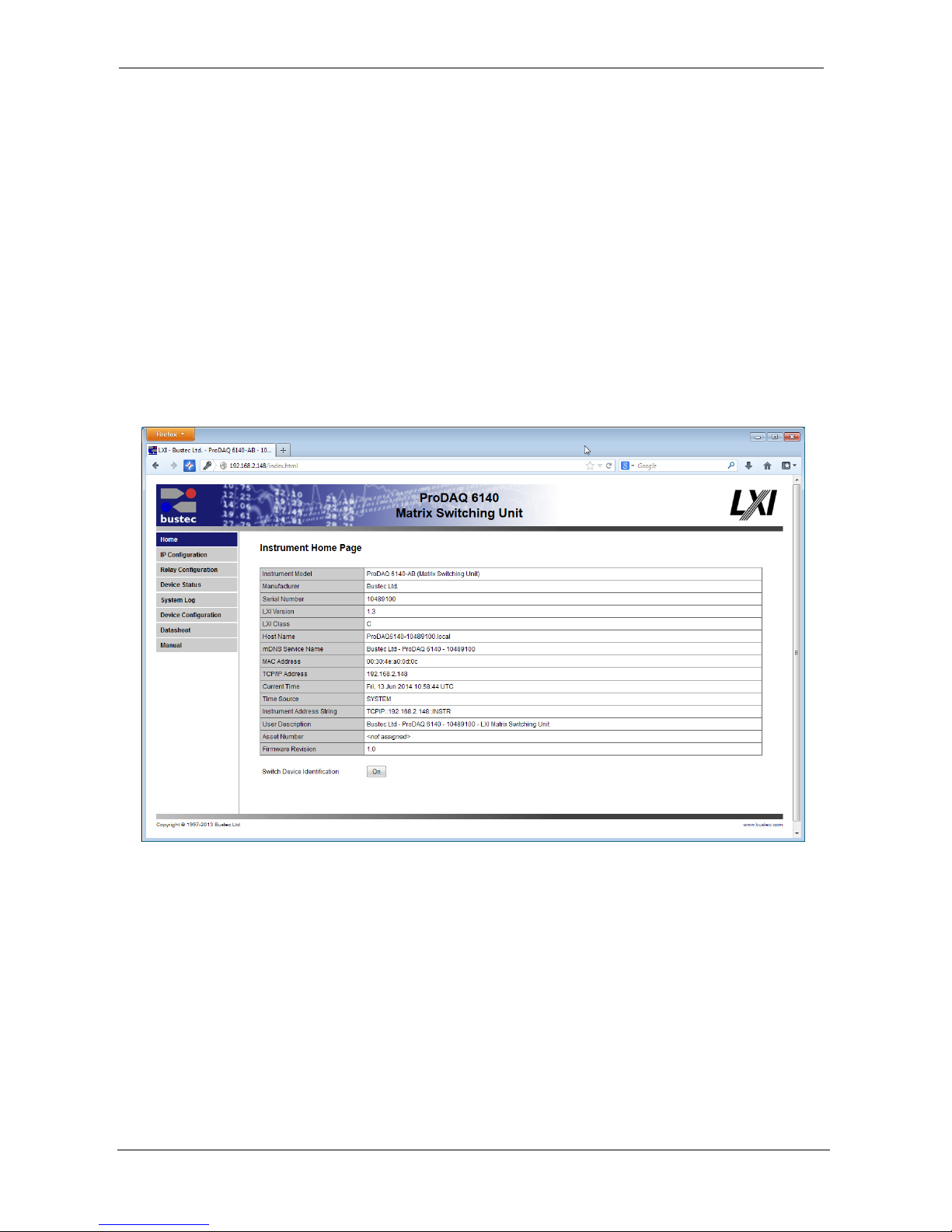
The instrument home page shows general information about the device like model number,
manufacturer, serial number, and revisions.
Figure 7 - Instrument Home Page
From here you can navigate to the different categories and pages by using the menu on the left
side. For security reasons, the configuration pages are protected by username and password,
which can be configured on the "Device Configuration" -> "Security Settings" page. Upon delivery,
they are set to:
username: admin
password: 1234
The <On/Off> button on the instrument home page allows you to identify physically the ProDAQ
6140 you are connected to. When you click onto the button, the LAN status indicator on the front
bezel will start flashing. A second click switches the LAN indicator off again.
Page 20
User Manual ProDAQ 6140 LXI Matrix Switching Unit
Copyright © 2017, Bustec Production Ltd. Page 18 of 56
4.2. IP Configuration
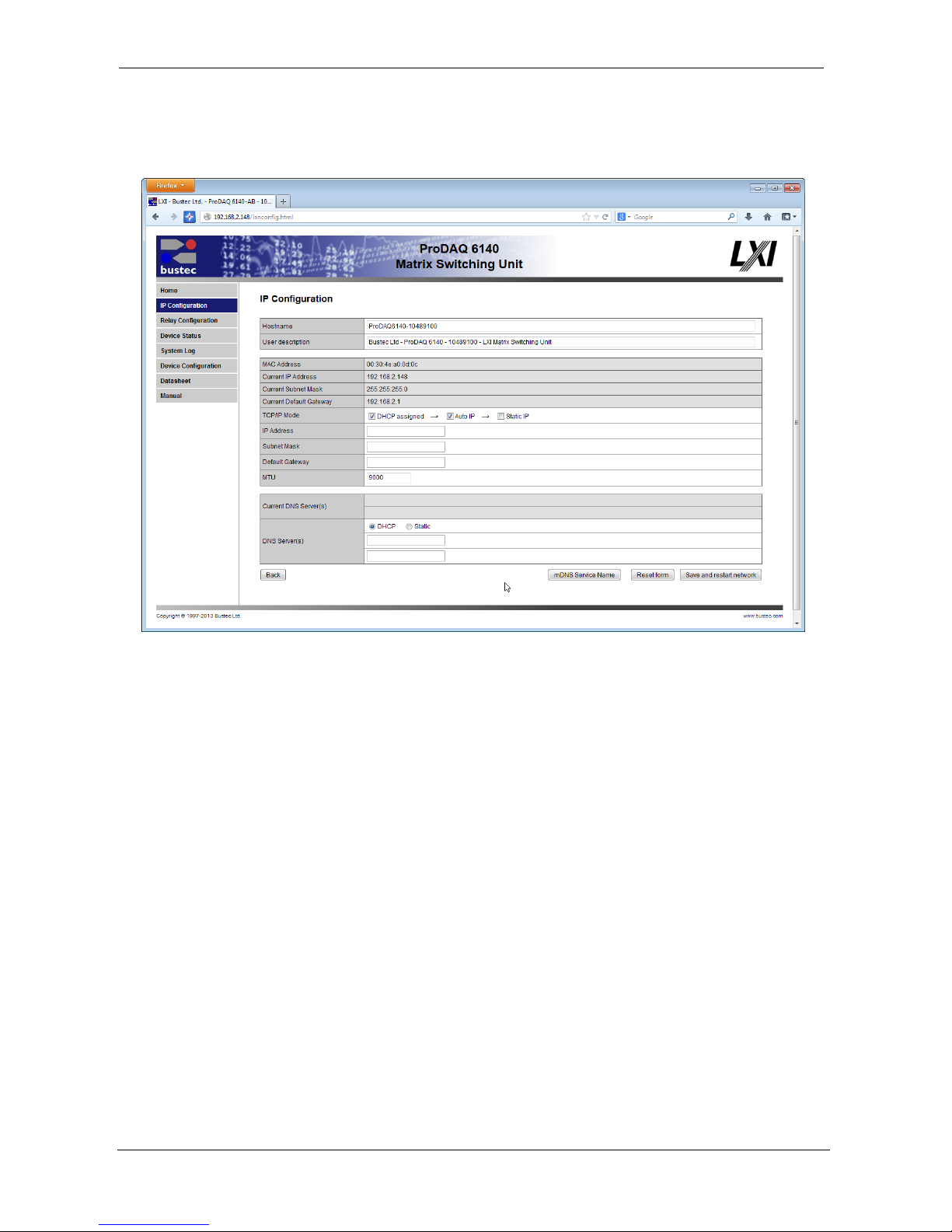
The IP Configuration Page allows you to change the settings for the ProDAQ 6140's LAN interface.
Figure 8 - IP Configuration Page
The IP Configuration page shows the current settings for the instruments LAN interface and allows
you to change and store the following settings:
Hostname
User defined hostname for the device (without domain).
Clear this value to revert to factory default.
Note: Multicast DNS domain is always: “.local”. Dynamic DNS domain
depends on the network configuration.
User Description
User defined description of the device – it is displayed on the Home
Page along with user defined Asset Number (see Device
Configuration).
Clear this value to revert to factory default.
MAC address
The MAC address of the ProDAQ 6140s network adapter.
Current IP configuration
Displays currently assigned: IP Address, Subnet Mask, Default
Page 21

ProDAQ 6140 LXI Matrix Switching Unit User Manual
Page 19 of 56 Copyright © 2017, Bustec Production Ltd.
Gateway and DNS servers.
TCP/IP mode
Specifies whether the device shall use a DHCP server in the network,
or AutoIP protocol to automatically obtain the IP configuration, or
maybe the static IP configuration defined in the form below.
More than one option may be selected. The priority is as follows:
DHCP → AutoIP → Static. For example, if DHCP and Static are
selected and DHCP fails, the Static configuration is set.
IP Address
If "Static IP" was selected as the TCP/IP mode, this field allows
assignment of a static IP address to the ProDAQ 6140s LAN
interface.
Subnet mask
If "Static IP" was selected as the TCP/IP mode, this field allows
assignment of a static subnet mask address to the ProDAQ 6140s
LAN interface.
Default Gateway
If "Static IP" was selected as the TCP/IP mode, this field allows
assignment of a static default gateway for the routing of IP packets.
DNS Servers
If "Static IP" was selected as the TCP/IP mode, these two fields allow
you to specify the DNS server the ProDAQ 6100 will use for name
resolving. If “DHCP” was selected as the TCP/IP mode, then it is
possible to select whether the DNS servers’ IP addresses shall be
acquired automatically (DHCP) or user-defined (Static).
MTU
Maximum Transmission Unit (MTU) – maximum size (in bytes) of an
IP packet that can be transmitted without fragmentation (including IP
headers, but excluding headers from lower levels in the protocol
stack).
The default value for a typical network is 1500 B. It can be defined as
high as 9000 B (jumbo frames). For correct interoperation, the whole
network must have the same MTU.
mDNS Service Name
User defined name of mDNS services that are advertised by the
ProDAQ 6140 device.
Clear this value to revert to factory default.
The device has a LAN reset mechanism that restores all the IP back to factory defaults. In order to
reset the settings press the “RST” button that can be found in the rear panel of the ProDAQ 6140
and wait for the device to reboot.
Page 22
User Manual ProDAQ 6140 LXI Matrix Switching Unit
Copyright © 2017, Bustec Production Ltd. Page 20 of 56
4.3. Relay Configuration
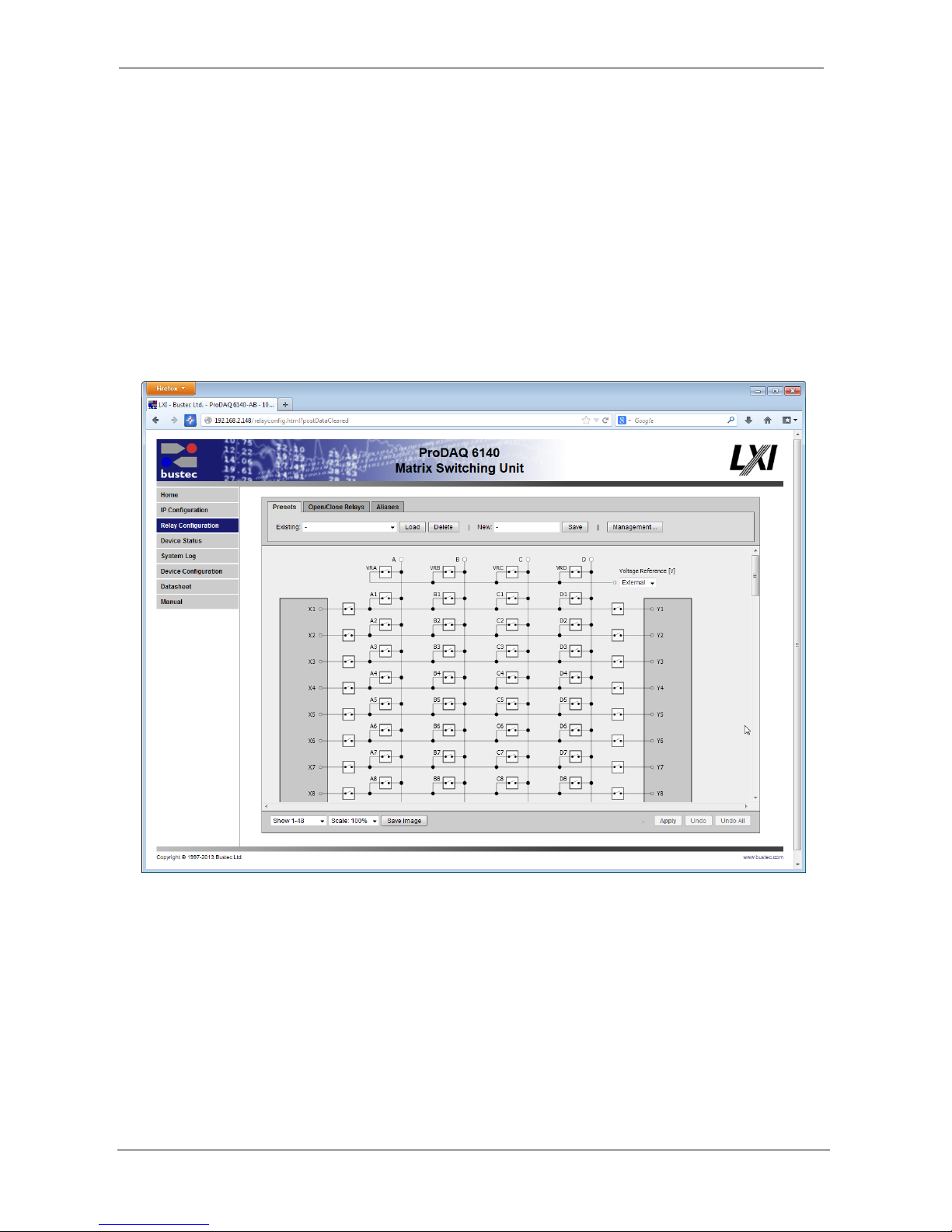
The Relay Configuration page provides user-friendly control over the whole relay matrix. The
graphical tool is divided into three parts (from top to bottom):
- A command area with three tabs allowing to select preset commands, relay group switch
commands and alias settings commands.
- The interactive schematic area which shows the current status of the physical connections
inside of the matrix and allows changing relay states, setting channel names (aliases) and
selecting voltage for the built-in voltage reference device (if fitted).
- The bottom bar with display options, image export capability and general apply and undo
buttons.
Figure 9 - Relay Configuration Page
By default, only the first 48 channels are displayed. It is because some web browsers may not
handle very big image canvases that would be required to display the whole relay matrix. Use the
combo box in the bottom left corner to select the range and scaling.
Page 23
ProDAQ 6140 LXI Matrix Switching Unit User Manual
Page 21 of 56 Copyright © 2017, Bustec Production Ltd.
4.3.1. Relay Operation
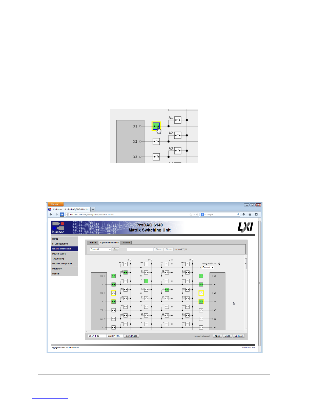
To change the state of the relays, you can operate single relays by just clicking a relay in the
displayed schematic or you can operate groups of relays by using the commands available in the
“Open/Close Relays” tab of the command area.
Changes to the relay states are not immediately applied on the device. Those being in a different
state than currently set on the device are marked with a yellow frame. To apply the changes, the
“Apply” button in the lower right corner of the window must be pressed. Only the relays which
states have been changed are affected. Before the changes are applied, they can be reverted by
pressing “Undo” and “Undo all” buttons.
Figure 10 - Single relay operation
Figure 10 shows relay X1 being switched to the “closed” state. After clicking on the relay, it is
changed to “closed” and marked with a yellow frame for being updated when the “Apply” button is
pressed. Closed relays are additionally marked green for a better overview.
Figure 11 - Toggling several relay states
Page 24
User Manual ProDAQ 6140 LXI Matrix Switching Unit
Copyright © 2017, Bustec Production Ltd. Page 22 of 56
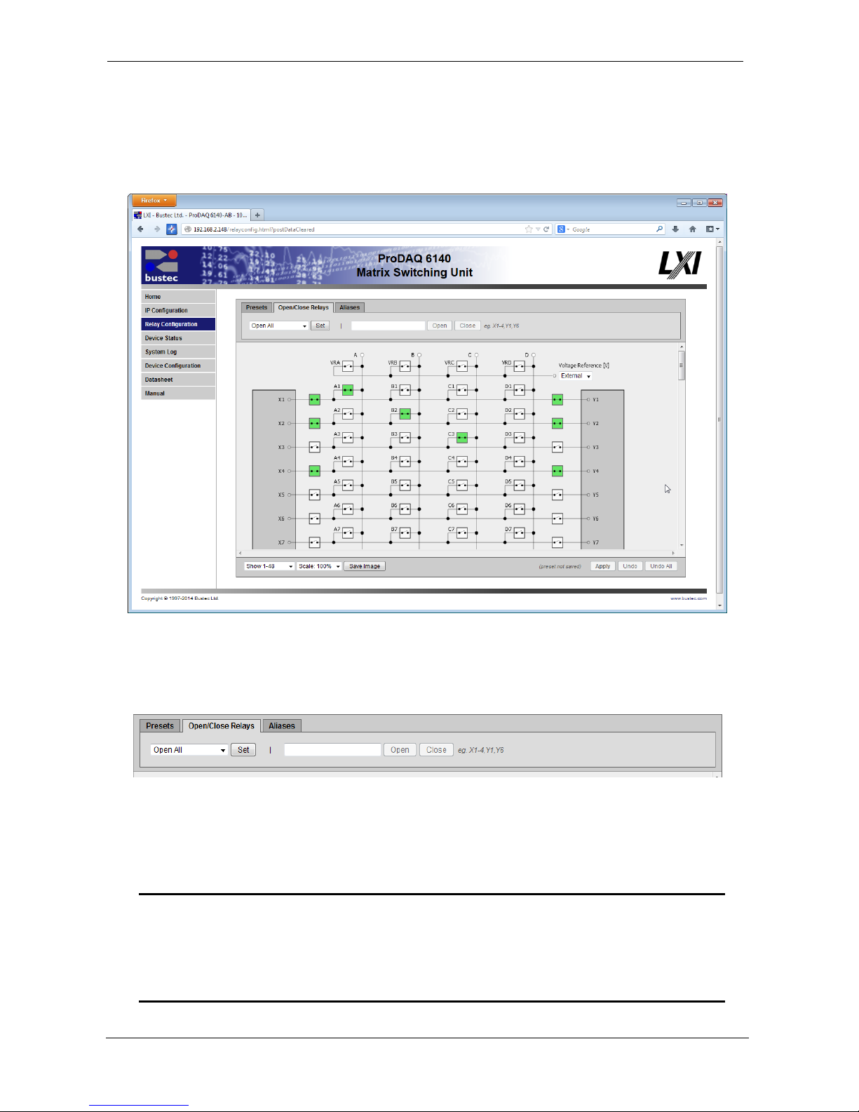
Figure 11 shows an example where the states of the relays X3, X4, Y3 and Y4 were toggled, but
the apply button wasn’t used to update the relays on the device. Relays X3 and Y3 were changed
from the “open” state to “closed” while relays X4 and Y4 were changed from “open” to “closed”.
Figure 12 shows the same schematic after the apply button was pressed.
Figure 12 - Applying the changes
Toggling the relays independently may sometimes be time consuming. In such a case the group
switching options available in the “Open/Close Relays” tab are useful.
Figure 13 - Open/Close Relays Tab
You can either choose a standard command from the drop-down list on the left and use the “Set”
button next to it, or type in a list expression in the text field on the right and use the “Open” or
“Close” buttons to open/close the relays contained in the list expression.
Note
Please note that these commands operate ONLY on the displayed schematic in the
same way a direct operation by clicking on a relay in the schematic operates. To
apply the changes to the device, the “Apply” button below the schematic must still
be used.
Page 25
ProDAQ 6140 LXI Matrix Switching Unit User Manual
Page 23 of 56 Copyright © 2017, Bustec Production Ltd.
The standard commands in the drop-down list allow opening all relays, opening all relays in one of
the columns (X, A, B, C, D, “Y”) or closing all relays in either the X or Y columns.
The list expression must be a comma separated list of single relays or relay ranges. Single relays
are expressed by using the letters “A”, “B”, “C”, “D”, “X” or “Y” for the column (signal connections
“X” and “Y” and bussed channel connections “A”, “B”, “C” or “D”) and a number channel number;
e.g. “X1”, “B23” or “Y99”. Relay ranges are expressed by using the same letters to select the
column and a starting and ending channel number separated by a dash “-“ (minus); e.g. “X2-6” or
“A1-180”.
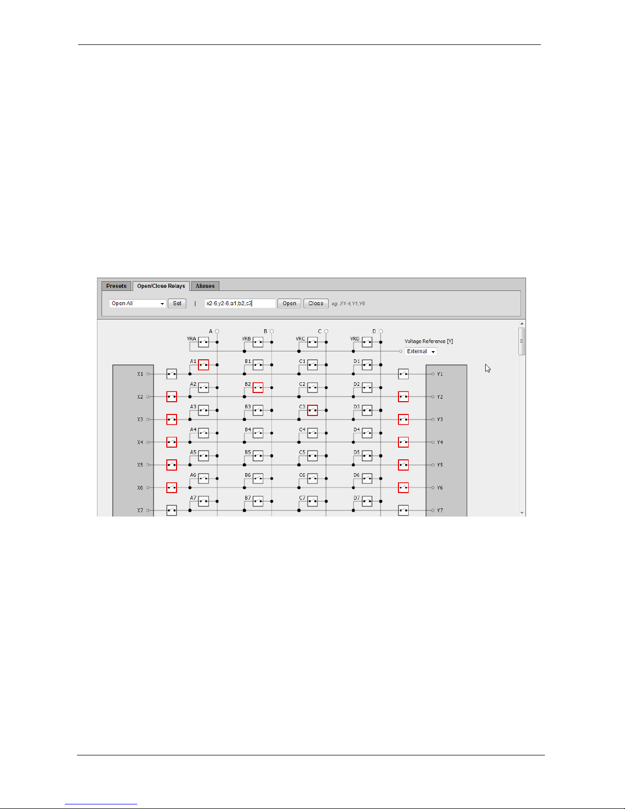
Figure 14shows an example of a list expression using both single relays and relay ranges:
“X2-6,Y2-6,A1,B2,C3”.
This list expression selects the “X” and “Y” relays for channel 2 to 6 as well as the “A” relay for
channel 1, the “B” relay for channel 2 and the “C” relay for channel 3.
Figure 14 - Using a list expression
The list expression is immediately checked while typing and the relays effected are marked with a
red frame in the schematic. In this way the correctness of the list expression can be checked
before pressing the “Open” or “Close” button to operate the selected relays in the schematic. If a
relay contained in a list expression is already in the correct state it is not affected by the command.
Once you press “Open” or “Close”, the affected relays are operated in the schematic and marked
with a yellow frame to be changed on the device when you press the “Apply” button below the
schematic.
4.3.2. Aliases
Individual channel names (aliases) can be assigned to all channels in the schematic for a better
overview during operation. The channel names are displayed next to the related connector. To
Page 26
User Manual ProDAQ 6140 LXI Matrix Switching Unit
Copyright © 2017, Bustec Production Ltd. Page 24 of 56
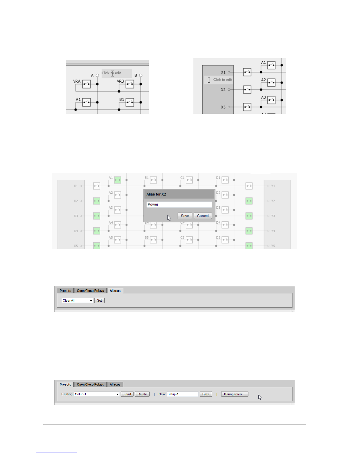
assign or edit a channel name, just hover the mouse next to connector until the text field shows its
selected state in a different color shade (see Figure 15) and click on it.
Figure 15 - Selecting a Channel Name (Alias) Field for Editing
Once clicked, a popup dialog with a text edit field allows you to enter or edit the alias. Press “Save”
to save the changes or “Cancel” to leave the dialog without applying the change.
Once an alias is edited, the change is immediately stored on the ProDAQ 6140 device. Each alias
can be up to 31 characters long.
Figure 16 - Editing the Channel Name (Alias) for Channel X2
To clear an alias, delete the name in the edit popup or use the commands in the drop-down list of
the “Aliases” tab in the command area to clear all or parts of the aliases.
Figure 17 - Aliases Tab
4.3.3. Presets
The entire device configuration of the ProDAQ 6140 can be stored on the device as a preset under
a name and reapplied by loading it. A device configuration (preset) consists of the relay settings,
assigned aliases as well as a voltage reference setting (if installed). Command to manage presets
can be found in the “Presets” tab in the command area.
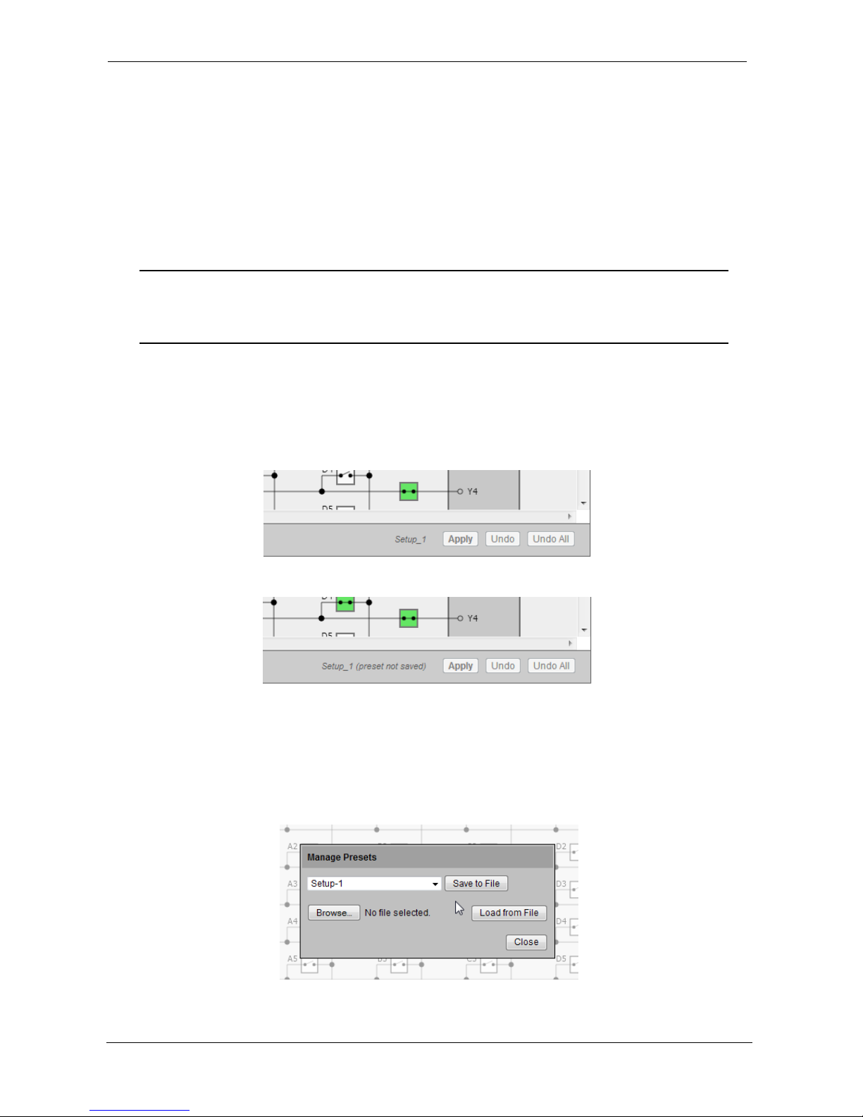
Figure 18 - Presets Tab
Page 27
ProDAQ 6140 LXI Matrix Switching Unit User Manual
Page 25 of 56 Copyright © 2017, Bustec Production Ltd.
To save a preset, type the name in the “New:” text field and press the “Save” button. The name can
be up to 31 characters long and can contain only alpha numeric characters, underscores and
hyphens. When a preset with the same name already exists, a warning message is displayed
asking for confirmation whether to overwrite it or not. If there are any unapplied changes made to
the relays (changes made to the schematic without applying them to the device) a dialog shows up
offering to update the device first.
To load and apply a previously stored preset select it in the “Existing” drop-down list and press
“Load”. This operation updates both the device and the schematic editor.
WARNING
When a preset is loaded, it is automatically applied on the ProDAQ 6140 device. All
the relays are set accordingly to the preset’s configuration.
If a preset was loaded, its name is displayed in the lower right corner next to the “Apply” button
(see Figure 19). If further changes to the device configuration are made by operating relays,
changing channel names etc and applying the changes to the device, a warning is shown that the
current configuration does not correspond any longer to the preset (“preset not saved”, see Figure
20)
Figure 19 - Preset Name Display
Figure 20 - “preset not saved” Warning
Presets can also be stored onto or loaded from the host computer running the web browser. To do
so, press the “Management…” button in the “Presets” tab in the command area. A popup dialog
appears where you can either select an existing preset in the drop-down list and use the “Save to
File” button to store it on the host computer or use the “Browse…” button to select a previously
stored preset and upload it to the device by pressing “Load from File”.
Figure 21 - Manage Presets Dialog
Page 28
User Manual ProDAQ 6140 LXI Matrix Switching Unit
Copyright © 2017, Bustec Production Ltd. Page 26 of 56
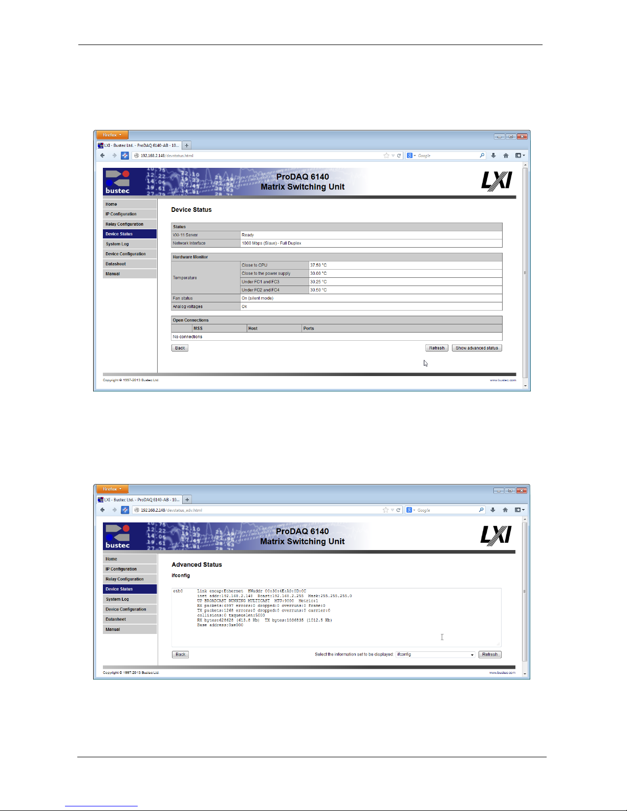
4.4. Device Status
The Device Status page displays the general status of the device like network connection status,
temperature readings, power monitor status and list of open connections.
Figure 22 - Device Status Page
4.5. Advanced Status
The Advanced Status page allows you to review the output of a number of embedded tools to
analyze the device status in more details.
Figure 23 - Advanced Status Page
Page 29
ProDAQ 6140 LXI Matrix Switching Unit User Manual
Page 27 of 56 Copyright © 2017, Bustec Production Ltd.
Figure 23 shows an example of the Advanced Status page showing the output of the embedded
“ifconfig” command. To select any of the available advanced status information, select one of the
items from the list and select the “Refresh” button. The following advanced status information is
currently available:
ifconfig
Displays the output of the embedded “ifconfig” command,
showing the settings for the Ethernet interface as seen by
the operating system.
route
Displays the output of the embedded “route” command,
showing the kernel routing table.
resolv.conf
Shows the contents of the “resolv.conf” file containing the
current name server settings.
hosts
Shows the contents of the local “hosts” file.
device.conf
Shows the contents of the device.conf file as created by the
embedded web interface. This file stores the information
specified by the IP setup page.
device and firmware
revision
Shows the current revisions of the different parts of the
system.
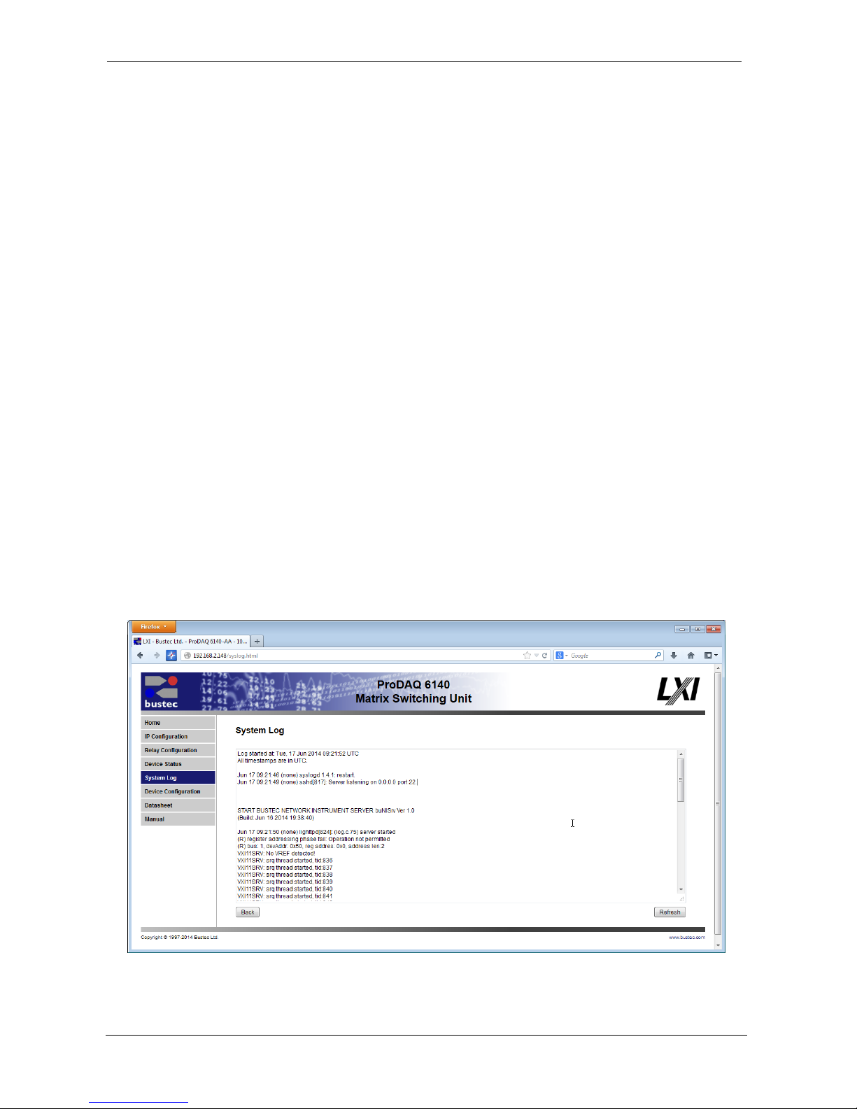
4.6. System Log
The System Log page shows the contents of the system log. Any housekeeping or debugging
information will be entered here by the operating system. To get an up-to-date status, press the
“Refresh” button below.
Figure 24 - System Log Page
Page 30
User Manual ProDAQ 6140 LXI Matrix Switching Unit
Copyright © 2017, Bustec Production Ltd. Page 28 of 56
4.7. Device Configuration
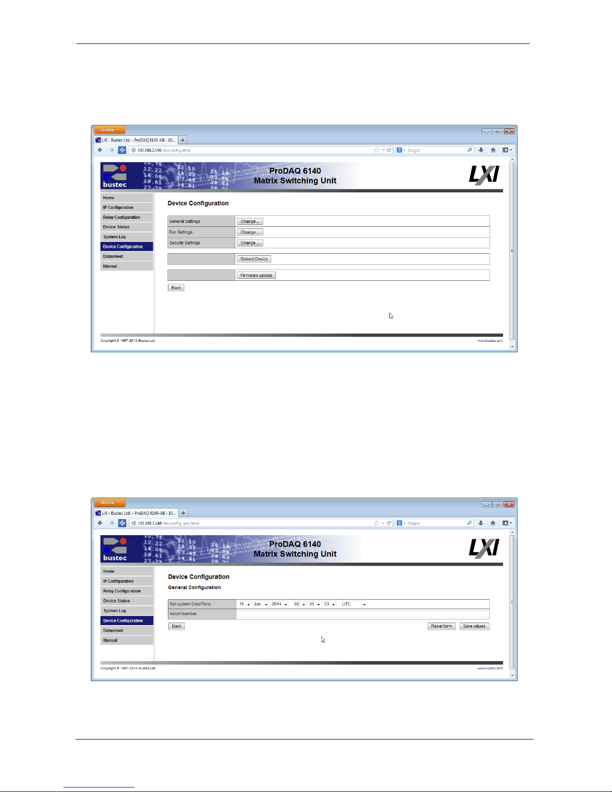
The Device Configuration page allows you to change several parameters of the internal
configuration of the device. In addition it allows you to reboot the device or update its firmware.
Figure 25 - Device Configuration Page
The device configuration is split up into several sub-items. Click on one of the “Change …” buttons
to the right of the different sections to access them. To reboot the device, select the “Reboot
Device” button. A reboot my take up to 30 seconds to complete. To update the firmware, select the
“Firmware Update” button to access the Firmware Update page.
4.7.1. General Settings
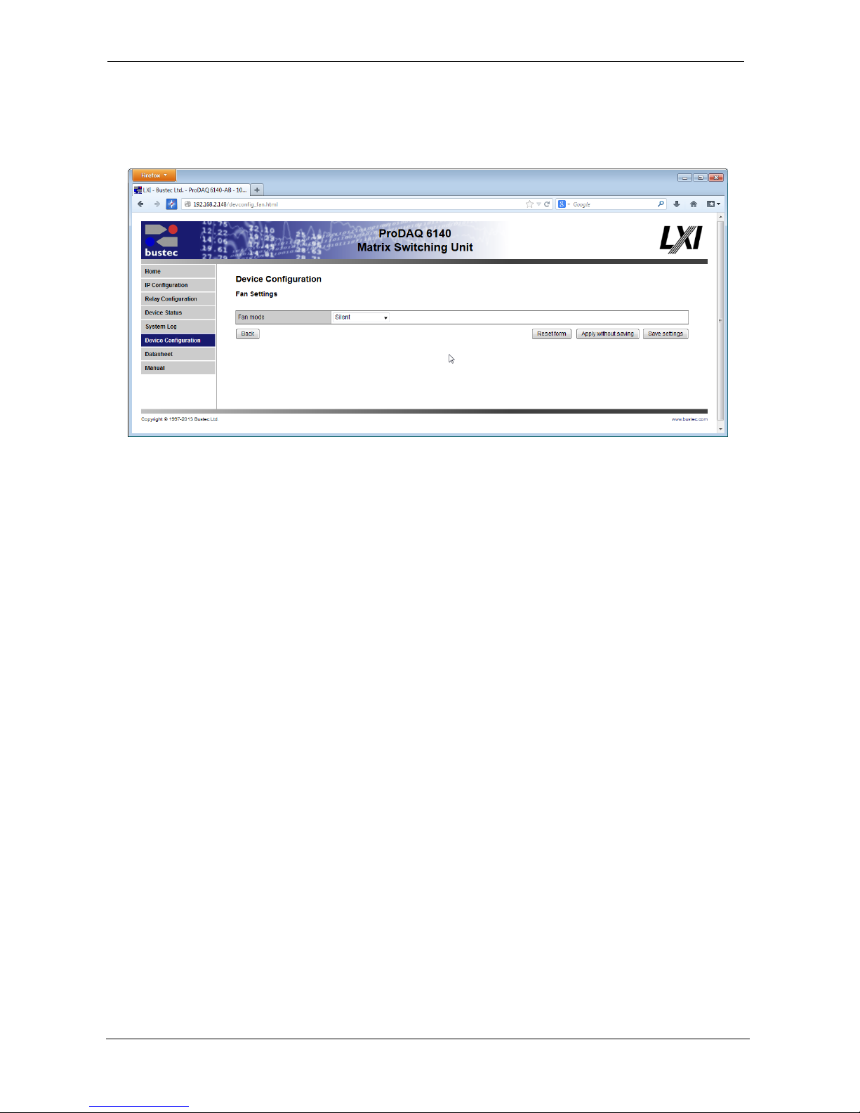
This page allows you to change the system time and assign an asset number to the device, which
will be shown on the instrument home page.
Figure 26 - General Settings Page
Page 31
ProDAQ 6140 LXI Matrix Switching Unit User Manual
Page 29 of 56 Copyright © 2017, Bustec Production Ltd.
4.7.2. Fan Settings
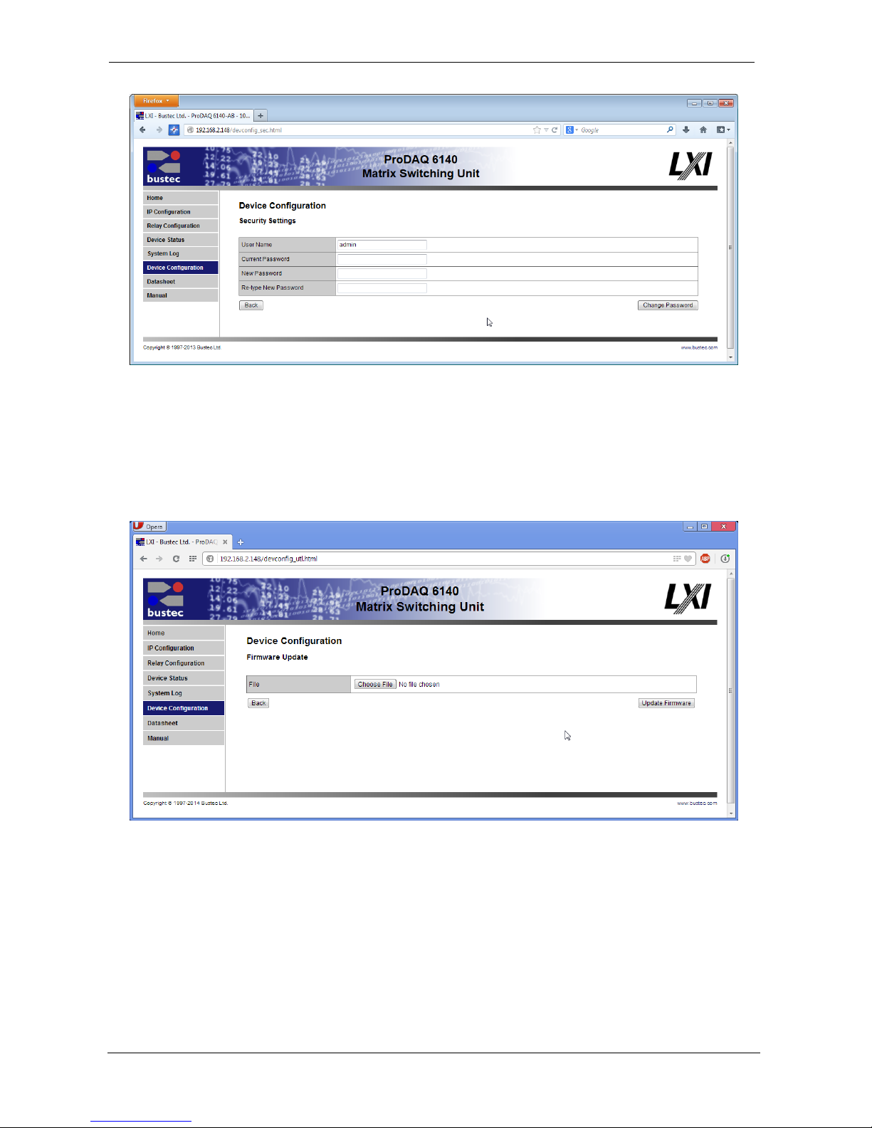
This page allows to configure how the unit operates its build-in fans.
Figure 27 - Fan Settings Page
There are two modes of operation:
Silent
The fans run at a low speed. This setting is not recommended
when the ambient temperature is high.
Normal
The fans run at full speed.
The “Apply without saving” button allows to apply the new setting without that it is saved as the new
default value. This means that the setting is only in effect until the next reboot of the device. On
reboot, the stored default setting is restored.
To save the setting as the new default value, use the “Save settings” button instead.
4.7.3. Security Settings
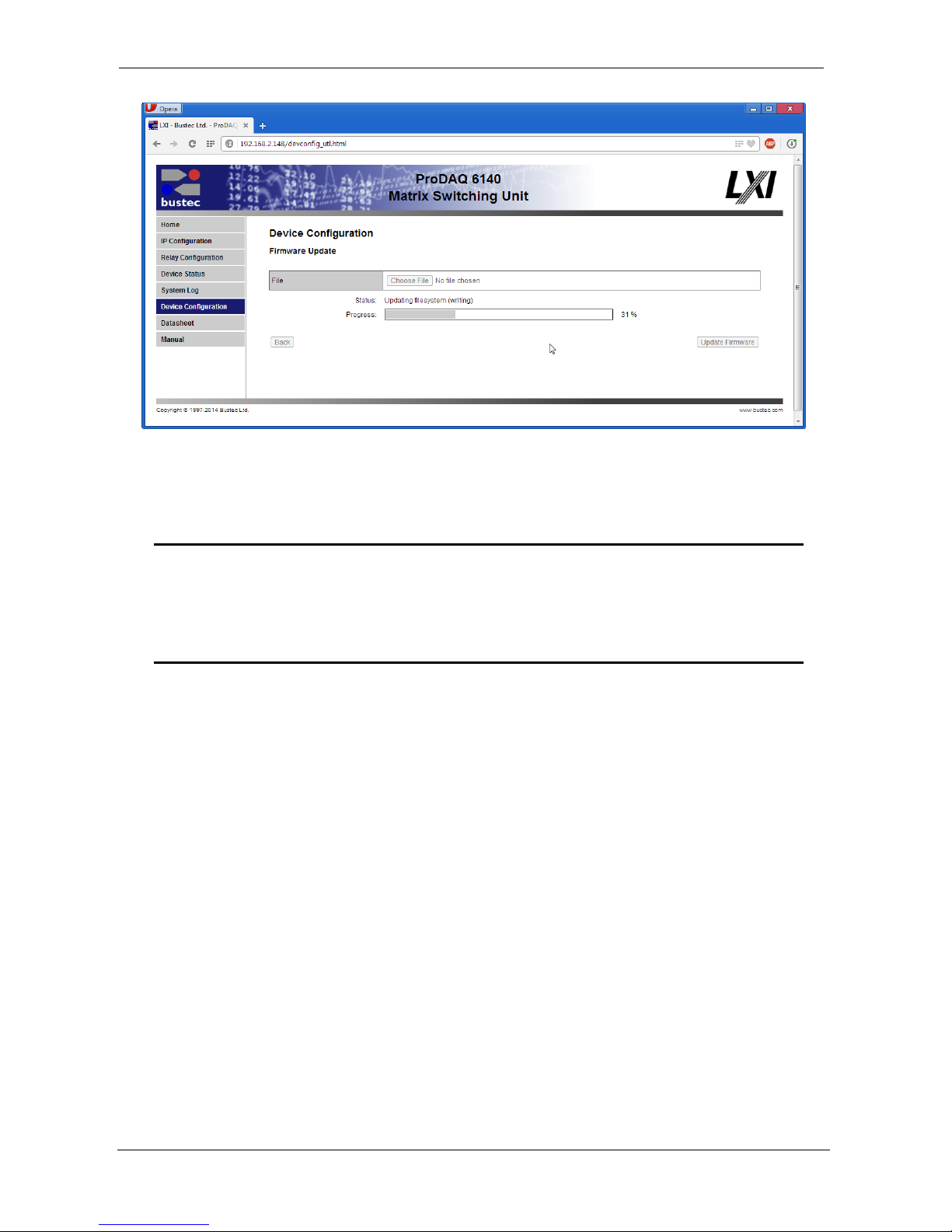
On this page you can change the password that is used to protect the pages of the ProDAQ 6100.
Please type in your old password, the new one and confirm it by re-typing.
Page 32
User Manual ProDAQ 6140 LXI Matrix Switching Unit
Copyright © 2017, Bustec Production Ltd. Page 30 of 56
Figure 28 - Security Settings Page
4.7.4. Firmware Update
To update the firmware on the ProDAQ 6140, use the “Update Firmware” button on the “Device
Configuration” page.
Figure 29 - Firmware Update Page
Before you can start a firmware update, make sure that the file is available on the host computer
where you run the internet browser. Press the "Browse..." to open the file upload dialog, which
allows you to browse through your file system and select the file to upload. Once the correct file is
selected, press the "Update Firmware" button. The upload progress and the programming progress
will be displayed by a progress bar below the file selection control (see Figure 30).
Page 33
ProDAQ 6140 LXI Matrix Switching Unit User Manual
Page 31 of 56 Copyright © 2017, Bustec Production Ltd.
Figure 30 - Firmware Update Progress
During the upload and programming, do not navigate away from the page by using the browser
controls. Any interruption of the update process might render the ProDAQ 6140 unusable.
Warning
Depending on your connection speed uploading and programming a new firmware
image may take several minutes. To safely complete the process, do not navigate
away from the page and do not interrupt the network connection or power-cycle the
ProDAQ 6140.
4.8. Datasheet and Manual Pages
The “Datasheet” and “Manual” pages allow you to view the ProDAQ 6140 datasheet and user
manual.
Page 34

User Manual ProDAQ 6140 LXI Matrix Switching Unit
Copyright © 2017, Bustec Production Ltd. Page 32 of 56
(This page was intentionally left blank.)
Page 35
ProDAQ 6140 LXI Matrix Switching Unit User Manual
Page 33 of 56 Copyright © 2017, Bustec Production Ltd.
5. Software Driver
To include operation of the ProDAQ 6140 LXI Matrix Switching Unit into your application, you need
to install one of the available software drivers on your computer. In addition to the driver according
to the IVI standard (IVI-C) as required by the LXI standard Bustec provides for users familiar with
the VXIplug&play standard a VXIplug&play driver. Both drivers require that a VISA library is
installed on the computer.
5.1. Installation
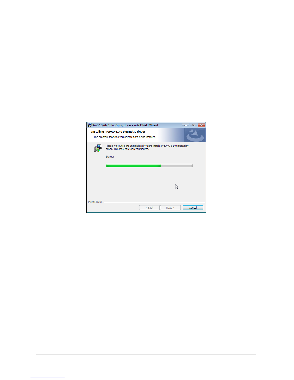
In order to install the software, run the ProDAQ 6140 installer package, 32 or 64 bit – appropriate
to the operating system, and accept the license agreement. The files are copied by default to the
IVIStandardRootDir respectively the VXIPNPPATH location.
Figure 31 - Example Installation Dialog
5.2. Soft Front Panel
The driver according to the VXIplug&play standard comes with a soft front panel application that
allows you to operate the device. It is a standalone application that has similar capabilities as the
ProDAQ 6140 WEB Interface. There are however some differences on the user experience level
that come from the differences between technologies used – HTTP with JavaScript vs. standalone
GUI application.
One of the advantages of using the Soft Front Panel application over the WEB interface is that it
allows working off-line. Working off-line it is possible to create and modify presets (saved states of
the device configuration) without a physical connection to a ProDAQ 6140.
5.2.1. Starting the Soft Front Panel
To start the soft front panel application, select it in the start menu (“Start” “Programs”
“VXIPNP” “ProDAQ 6140” “Soft Front Panel”). After the start of the soft front panel
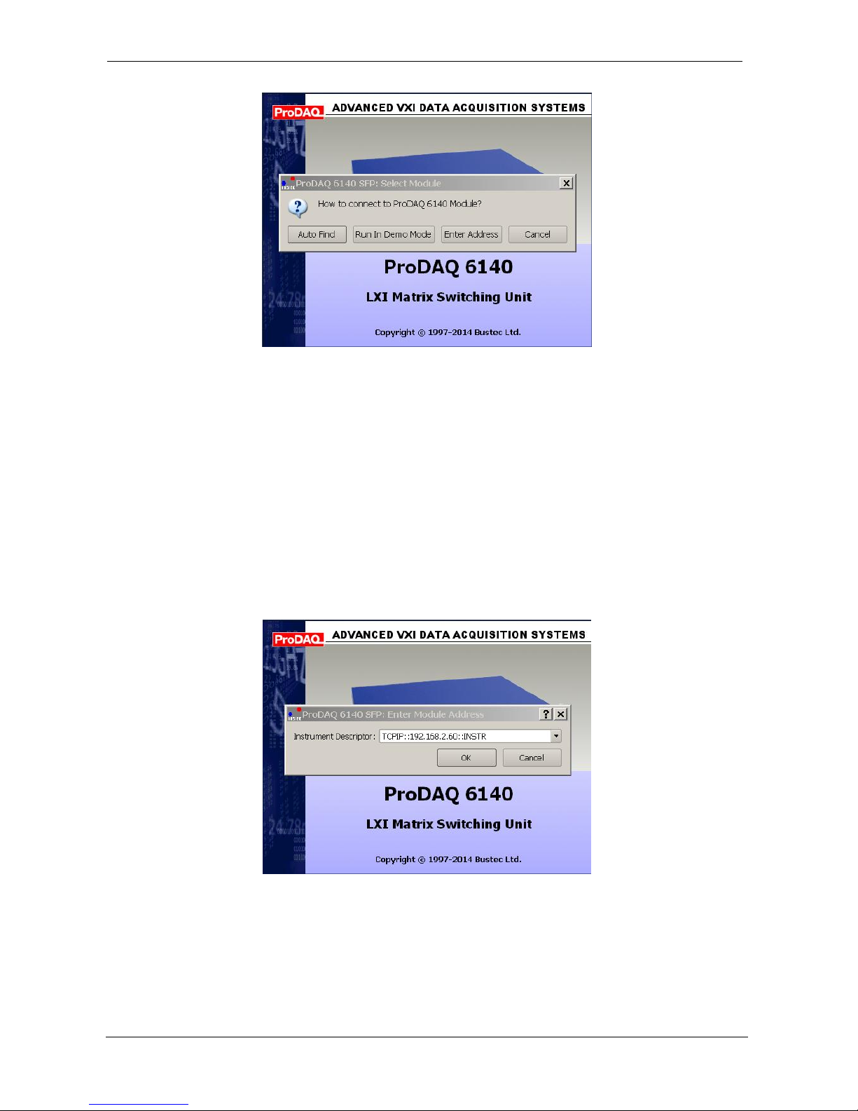
application, the user has the choice to either enter the address information (VISA resource
specification) of the ProDAQ 6140 the soft front panel application shall connect to, use the build-in
auto find functionality to discover accessible ProDAQ 6140 units cards or run in demo mode.
Page 36
User Manual ProDAQ 6140 LXI Matrix Switching Unit
Copyright © 2017, Bustec Production Ltd. Page 34 of 56
Figure 32 - Selecting the Connection Method
Please note that when using the Bustec VISA library, the auto find functionality will only inspect
network resources that are known to the VISA library to avoid unwanted accesses of network
resources that might be unintentionally reachable via the local network. Use the Bustec VISA
Configuration Tool to find and manage network instruments (refer to the Bustec VISA library and
Tools Manual for details).
If “Auto Find” is selected, the user will be presented with a dialog box showing all available ProDAQ
6140 units, allowing the selection of the one unit to connect to. If there is only one unit available,
the dialog box will not appear and the soft front panel application will automatically establish the
communication to this instrument.
If “Enter Address” is selected, a dialog is shown that allows you to directly enter VISA resource
string using the IP address or host name of the instrument.
Figure 33 - Specifying the Instrument Address
If no ProDAQ 6140 is available in your system or to create/edit presets, the soft front panel
application can be run in demo (offline) mode.
Page 37
ProDAQ 6140 LXI Matrix Switching Unit User Manual
Page 35 of 56 Copyright © 2017, Bustec Production Ltd.
Offline Operation (Demo Mode)
The biggest advantage of using the Soft Front Panel application over the WEB interface is that it
allows working off-line in demo mode. When in demo mode, the device operation is completely
simulated. It is allowed to switch the relays, set aliases, save, load, export and import presets, etc.
All the settings are stored in Windows Registry and therefore are not lost when program is
restarted.
The main purpose for working off-line is that it is possible to create and modify presets without
physical connection to ProDAQ 6140. A preset can be imported from and exported to a file. The file
for import can be taken from the real device for modification and the exported file can be uploaded
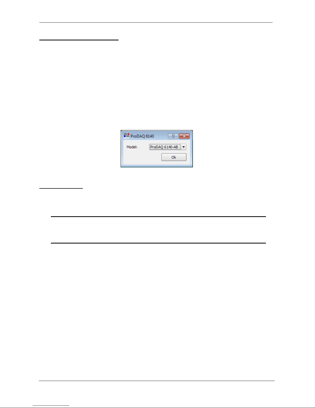
to ProDAQ 6140. Please note that there are two types of preset files that are not compatible with
each other – for the AA and AB models. Therefore if you select “Demo Mode” from the dialog
shown in Figure 32, an additional dialog allows you to choose the model which shall be used in
offline mode.
Figure 34 - Demo Mode Model Selection
Online Operation
When the Soft Front Panel works in online mode, the “Active” LED indicator that can be found in
the upper right corner of the main window is green.
WARNING
Working in online mode means that all the applied changes are immediately applied
to the connected ProDAQ 6140.
5.2.2. Operating the Soft Front Panel
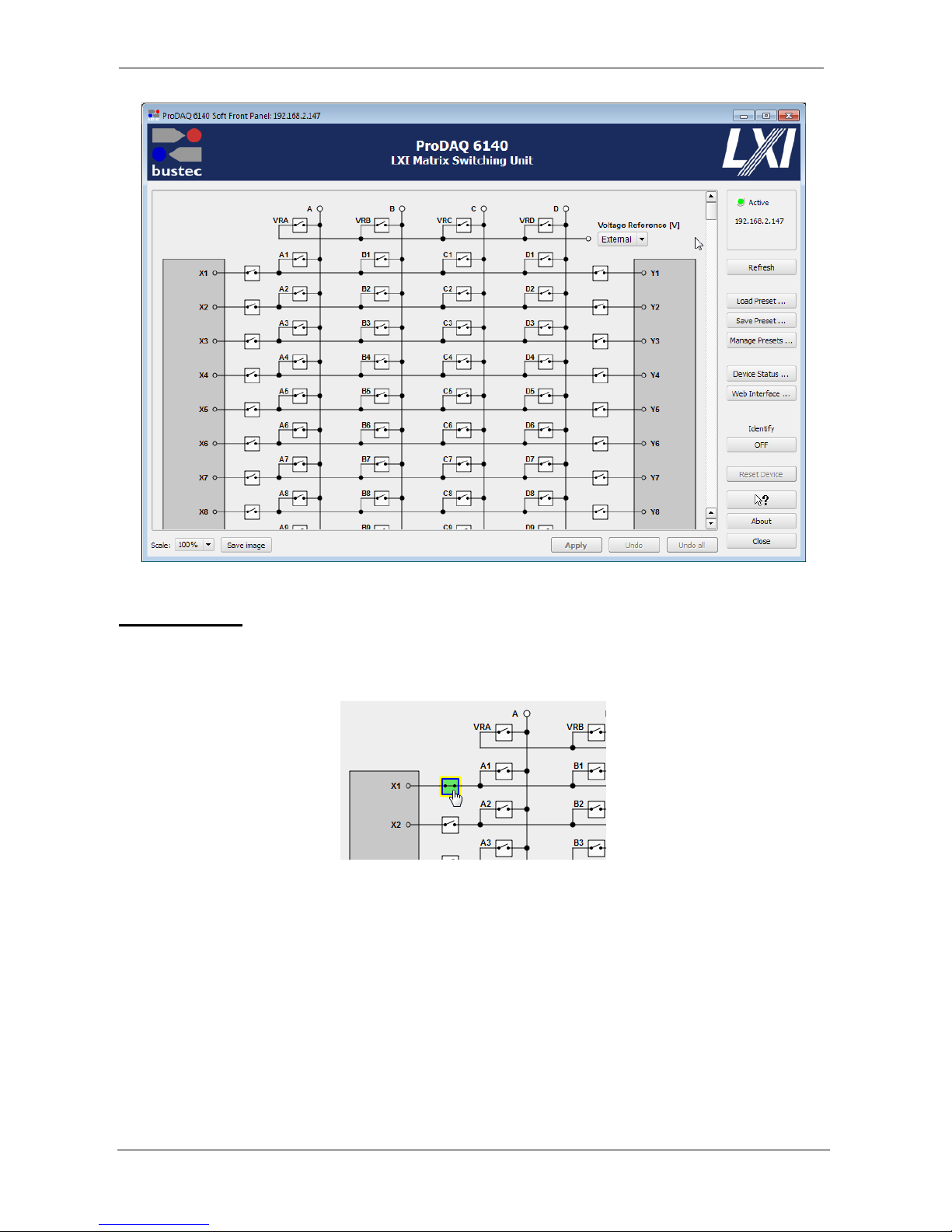
The Soft Front Panel application allows user-friendly control over the whole relay matrix. Its main
window is divided into three parts:
- The interactive schematic area which shows the physical connections inside of the matrix. It
also allows changing the relay states, setting channel names (aliases), selecting voltage for the
built-in Voltage Reference device (if fitted) and letting some additional operations on groups of
relays at once.
- The bottom bar with display options, image export capability and what is most important –
Apply and Undo buttons.
- Additional options grouped in a panel on the right side of the window.
Page 38
User Manual ProDAQ 6140 LXI Matrix Switching Unit
Copyright © 2017, Bustec Production Ltd. Page 36 of 56
Figure 35 -Soft Front Panel Application User Interface
Relay Operation
In order to switch the state of a relay just click on it on the schematic. Closed relays are marked
with green color for clarity.
Figure 36 - Switching a Relay to its “Closed” State
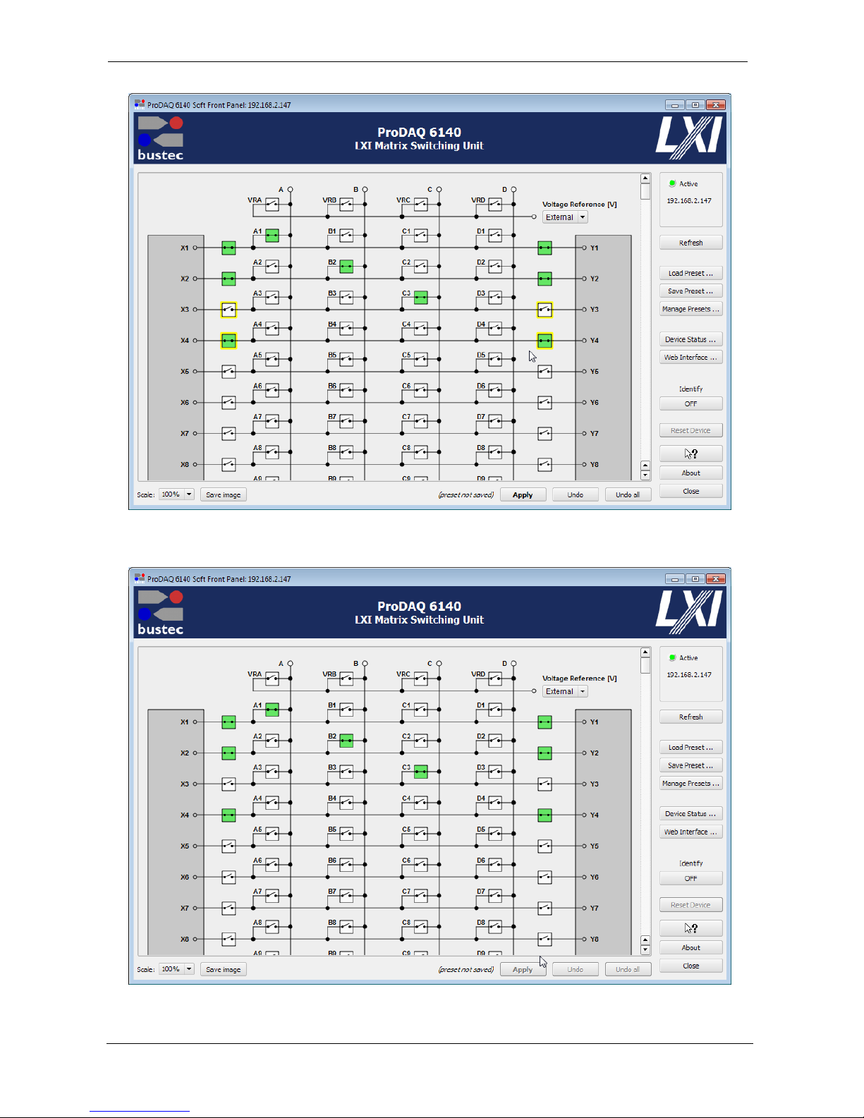
The relays are not immediately switched on the ProDAQ 6140. Those being in a different state
than is currently set on the device are additionally marked with a yellow frame. The last changes
that haven’t been written to the device yet can be reverted by pressing “Undo” and “Undo all”
buttons. The same applies to the built-in Voltage Reference’s setting.
To apply the changes and write them to the device, the “Apply” button in the lower right corner of
the main window must be pressed. Only the relays which states have been changed are affected.
Page 39
ProDAQ 6140 LXI Matrix Switching Unit User Manual
Page 37 of 56 Copyright © 2017, Bustec Production Ltd.
Figure 37 - Relays X3, X4, Y3 and Y4 are toggled, but not switched on the ProDAQ 6140
Figure 38 - After Apply Button was pressed
Page 40
User Manual ProDAQ 6140 LXI Matrix Switching Unit
Copyright © 2017, Bustec Production Ltd. Page 38 of 56
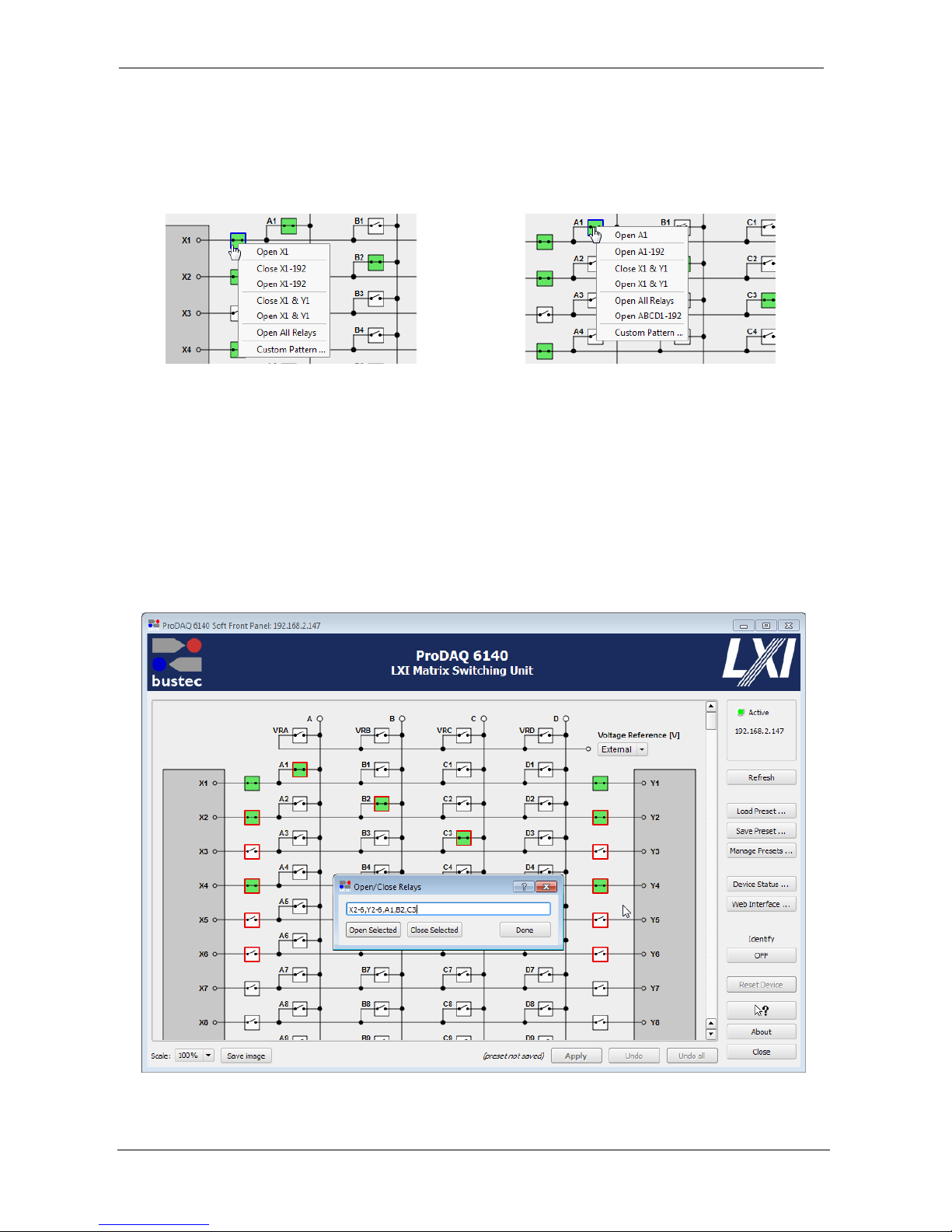
Toggling the relays independently may sometimes be time consuming. In such a case the group
switching options available in the context menus for each of the relays are useful. They allow
opening all relays, or opening the whole column: X, Y, A, B, C , or D. Also closing the whole X or Y
column is possible. When the “Custom Pattern…” option is selected, the user can enter a list
expression describing the group of relays to be switched.
Figure 39 - Relay Context Menus
The list expression must be a comma separated list of single relays or relay ranges. Single relays
are expressed by using the letters “A”, “B”, “C”, “D”, “X” or “Y” for the column (signal connections
“X” and “Y” and bussed channel connections “A”, “B”, “C” or “D”) and a number channel number;
e.g. “X1”, “B23” or “Y99”. Relay ranges are expressed by using the same letters to select the
column and a starting and ending channel number separated by a dash “-“ (minus); e.g. “X2-6” or
“A1-180”.
Figure 40 shows an example of a list expression using both single relays and relay ranges. The list
expression selects the “X” and “Y” relays for channel 2 to 6 as well as the “A” relay for channel 1,
the “B” relay for channel 2 and the “C” relay for channel 3.
Figure 40 - Using a List Expression
Page 41
ProDAQ 6140 LXI Matrix Switching Unit User Manual
Page 39 of 56 Copyright © 2017, Bustec Production Ltd.
Aliases
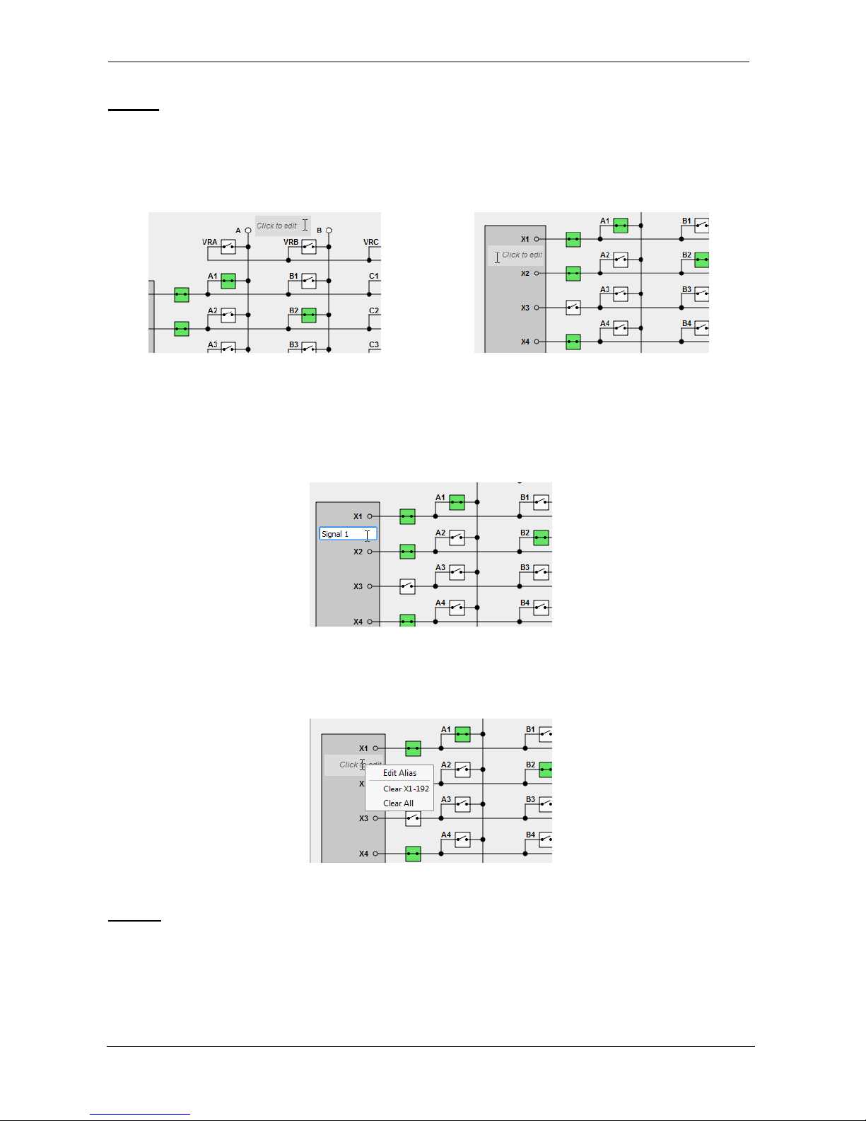
Individual channel names (aliases) can be assigned to all channels in the schematic for a better
overview during operation. The channel names are displayed next to the related connector. To
assign or edit a channel name, just hover the mouse next to connector until the text field shows its
selected state in a different color shade (see Figure 41) and click on it.
Figure 41 - Selecting a Channel Name (Alias) Field for Editing
Once clicked, a text edit field allows you to enter or edit the alias. Press “Enter” to save the change
made. Once an alias is edited, the change is immediately stored on the ProDAQ 6140 device. Each
alias can be up to 31 characters long.
Figure 42 - Editing the Alias for Channel X1
To clear an alias, delete the name in the edit field or use the popup context menu which is available
by doing a right-click on the alias.
Figure 43 - Alias Context Menu Example
Presets
The presets are device configuration states saved to files and stored on the ProDAQ 6140 device.
It is possible to save any state that is currently set on the device including not only all the relay
states, but also the aliases and voltage reference setting.
Page 42
User Manual ProDAQ 6140 LXI Matrix Switching Unit
Copyright © 2017, Bustec Production Ltd. Page 40 of 56
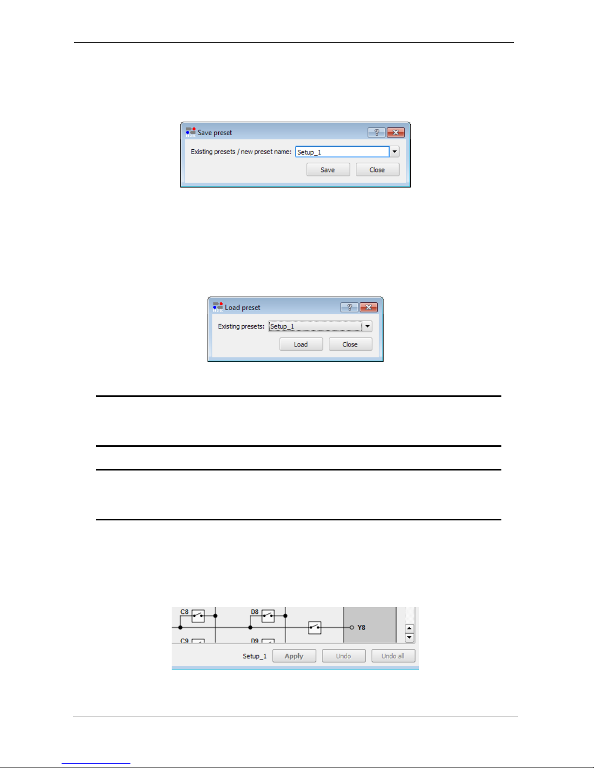
In order to save a preset please apply the relay state changes that were made on the page, but
haven’t been written to the device yet. Then press “Save Preset…” button to open the confirmation
dialog window and type the new preset name, or select an existing preset to be overwritten. If there
were unapplied changes made to the relays, a warning dialog appears asking whether to apply and
continue, or cancel.
Figure 44 - Save Preset Dialog
The name of a preset can be up to 63 characters long and can contain only alpha numeric
characters, underscores and hyphens. When a preset with the same name already exists a
warning message is displayed asking for confirmation whether to overwrite it or not.
To load a previously stored preset just press the “Load Preset…” button in the main window and
choose one from the drop down list.
Figure 45 - Load Preset Dialog
Note
Creating a preset requires either setting the desired configuration on the ProDAQ
6140 device or to run the Soft Front Panel offline in demo mode.
WARNING
When a preset is loaded, it is automatically applied on the ProDAQ 6140 device. All
the relays are set accordingly to the preset’s configuration.
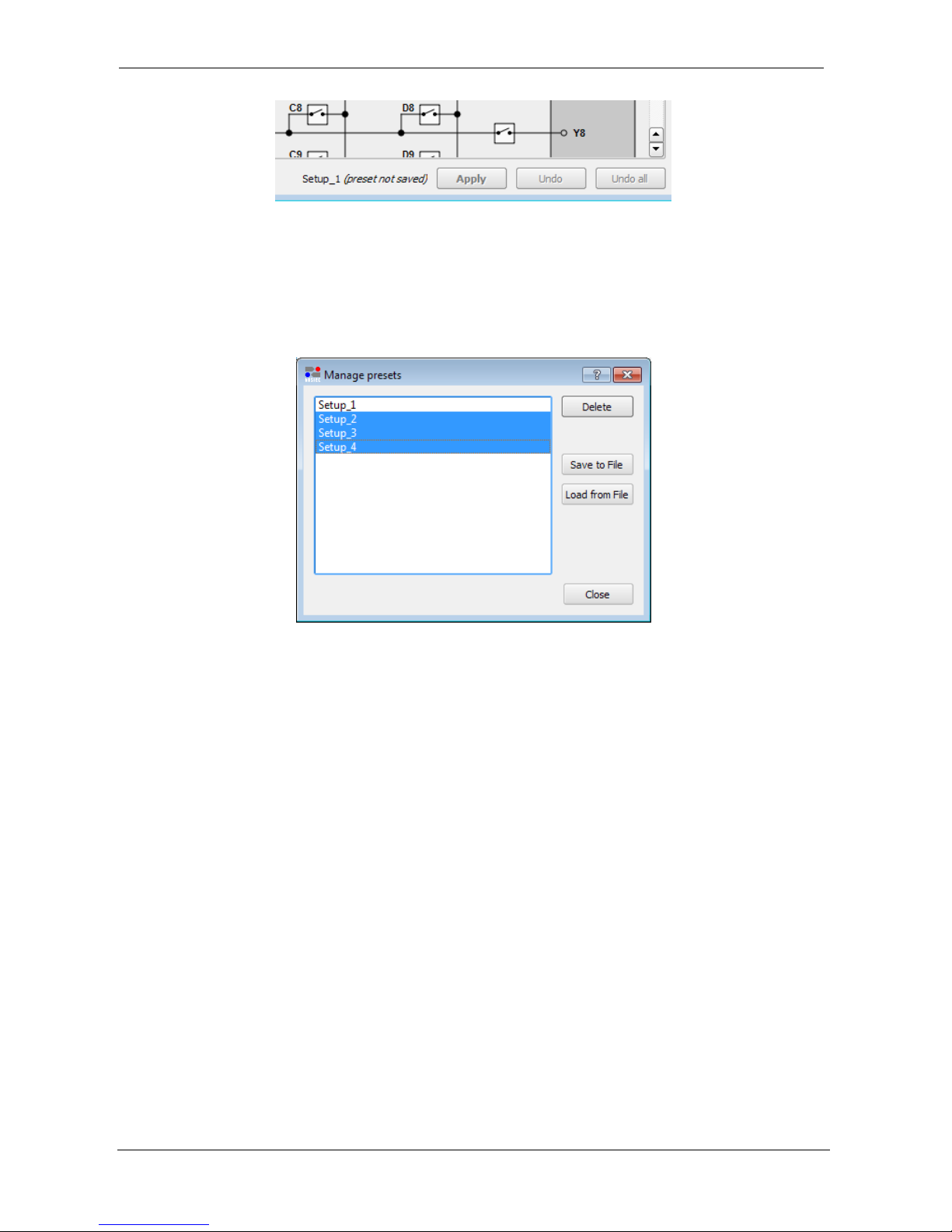
If a preset was loaded or saved, its name is displayed in the lower right corner next to the “Apply”
button (see Figure 46). If further changes to the device configuration are made by operating relays,
changing channel names etc and applying the changes to the device, a warning is shown that the
current configuration does not correspond any longer to the preset (“preset not saved”, see Figure
47)
Figure 46 - Preset Name Display
Page 43
ProDAQ 6140 LXI Matrix Switching Unit User Manual
Page 41 of 56 Copyright © 2017, Bustec Production Ltd.
Figure 47 - “preset not saved” Warning
More preset handling options are available when the “Manage Presets…” button is pressed. It
opens a dialog where it is possible to delete presets or export them from the ProDAQ 6140 device
to files on local or network storage device. The opposite is also possible – the user can import
previously stored presets to ProDAQ 6140.
Figure 48 - Manage Presets Dialog
To save preset(s), select one or multiple presets from the list and press “Save to File”. To import
presets, press “Load from File” and select the file(s) in the “Load presets” dialog shown. To import
multiple presets, hold the “Ctrl” key down while selecting files in the “Load presets” dialog.
The presets exported in online mode can be later imported using the Soft Front Panel working
offline and vice versa.
Page 44

User Manual ProDAQ 6140 LXI Matrix Switching Unit
Copyright © 2017, Bustec Production Ltd. Page 42 of 56
5.3. Using the VXIplug&play Driver
This chapter shows how to operate the ProDAQ 6140 LXI Matrix Switching Unit using the
VXIplug&play driver. The code section(s) shown are used to explain the basic functionality only,
complete examples can be found in the “Examples” subdirectory of the driver. All functions are
explained in detail in the help file coming with the driver.
5.3.1. Connecting to the device
To initialize the driver and connect to the ProDAQ 6140, the standard VXIplug&play initialization
function bu6140_init() is used. The resource string can use the form shown in section 3.5.1 if
mDNS is used (see Figure 49, ) or the IP address of the device (see Figure 49, ).
Please refer to the VXIplug&play standard VPP-4.3, section 4.3 for a detailed description of the
address string used.
Figure 49 - Connecting to the ProDAQ 6140
WARNING
To maintain the relay states when starting and stopping your application, you need
to set the <resetDevice> parameter of the bu6140_init() function to VI_FALSE
as shown above. Specifying VI_TRUE will reset all relays to their default state
(“open”) when you connect to the device.
To close a session with the ProDAQ 6140 LXI Matrix Switching Unit, the standard VXIplug&play
function bu6140_close() must be used.
#include <visa.h>
#include <bu6140.h>
main (int argc, char **argv)
{
ViStatus status;
ViSession session;
ViChar descr[256];
/* connect to the ProDAQ 6140 using mDNS host name */
if ((status = bu6140_init(“TCPIP0::prodaq6140-<SERIAL NO>.local::INSTR”,
VI_TRUE, VI_FALSE, &session)) < VI_SUCCESS)
{
bu6140_error_message(session, status, errMsg);
printf (“Error: bu6140_init() failed due to %s\n”, descr);
return -1;
}
/* OR: connect to the ProDAQ 6140 unit using the device IP address */
if ((status = bu6140_init(“TCPIP0::192.168.168.192::INSTR”,
VI_TRUE, VI_FALSE, &session)) < VI_SUCCESS)
{
bu6140_error_message(session, status, errMsg);
printf (“Error: bu6140_init() failed due to %s\n”, descr);
return -1;
}
/* ... */
bu6140_close (session);
}
Page 45

ProDAQ 6140 LXI Matrix Switching Unit User Manual
Page 43 of 56 Copyright © 2017, Bustec Production Ltd.
5.3.2. Operating Relays
To operate a single relay, the driver function bu6140_setRelayState() can be used (see Figure
50, ). As parameters you need to specify the relay column (channel I/Os “X”, “Y” or bus lines “A”,
“B”, “C” and “D”), the row (1-96 for ProDAQ 6140 versions “AA” and “BA” or 1-192 for ProDAQ
6140 versions “AB” and “BB”) and the state the relay shall be switched to. The relay column as well
as the relay state can be specified using a predefined macro from the bu6140.h include file or the
corresponding numerical value (see driver help file). Predefined macros for the matrix columns are
bu6140_CHANNEL_X for the relay connecting the channel I/O “X”
bu6140_CHANNEL_Y for the relay connecting the channel I/O “Y”
bu6140_LINE_A for the relay connecting line “A” to the row
bu6140_LINE_B for the relay connecting line “B” to the row
bu6140_LINE_C for the relay connecting line “C” to the row
bu6140_LINE_D for the relay connecting line “D” to the row
Figure 50 - Operating a Relay
The function bu6140_getRelayState() can be used to inquire the current status of a relay in the
same way (see Figure 50, ).
To switch multiple relays with one command, the function bu6140_changeMatrixState() can be
used (see Figure 51, ). It receives as parameter two arrays with 32-bit values. The first array
contains a bit mask where, if a bit is set to one (1), the corresponding relay is switched to its “open”
state, while the second array contains a bit mask where, if a bit is set to one (1), the corresponding
relay is switched to its “closed” state. Bits that are zero “0” will leave the state of the corresponding
relay unchanged. For the ProDAQ 6140 versions “AA” and “BA” the array must contain 18 values;
for the versions “AB” and “BB” it must contain 36 values. The bits in the bit masks correspond to
the relays in the way as shown in Table 1 and Table 2 ( also Figure 51, and ). When executing
#include <visa.h>
#include <bu6140.h>
main (int argc, char **argv)
{
ViStatus status;
ViSession session;
ViChar descr[256];
ViBoolean state;
/* ... */
/* switch the relay connecting line “C” in row 6 to “open” */
if ((status = bu6140_setRelayState (session, bu6140_LINE_C, 6, bu6140_OPEN)) < VI_SUCCESS)
{
bu6140_error_message (session, status, errMsg);
printf (“Error: bu6140_setRelayState() failed due to %s\n”, descr);
bu6140_close (session);
return -1;
}
/* inquire the relay state of the relay connecting line “C” in row 6 */
if ((status = bu6140_getRelayState (session, bu6140_LINE_C, 6, &state)) < VI_SUCCESS)
{
bu6140_error_message (session, status, errMsg);
printf (“Error: bu6140_getRelayState() failed due to %s\n”, descr);
bu6140_close (session);
return -1;
}
/* ... */
}
Page 46

User Manual ProDAQ 6140 LXI Matrix Switching Unit
Copyright © 2017, Bustec Production Ltd. Page 44 of 56
this function, first all relays specified in the “open” mask are switched to their “open” state, then the
relays specified in the “close” mask are switched to their “closed” state.
Array Index
MSB LSB
0
Row 32
Channel I/O “X”
Row 1
1
Row 64
Channel I/O “X”
Row 33
2
Row 96
Channel I/O “X”
Row 65
3
Row 32
Channel I/O “Y”
Row 1
4
Row 64
Channel I/O “Y”
Row 33
5
Row 96
Channel I/O “Y”
Row 65
6
Row 32
Line “A”
Row 1
7
Row 64
Line “A”
Row 33
8
Row 96
Line “A”
Row 65
9
Row 32
Line “B”
Row 1
10
Row 64
Line “B”
Row 33
11
Row 96
Line “B”
Row 65
12
Row 32
Line “C”
Row 1
13
Row 64
Line “C”
Row 33
14
Row 96
Line “C”
Row 65
15
Row 32
Line “D”
Row 1
16
Row 64
Line “D”
Row 33
17
Row 96
Line “D”
Row 65
Table 1 - Pattern Contents for 6140 Versions “AA” and “BA”
Array Index
MSB LSB
0
Row 32
Channel I/O “X”
Row 1
•••
•••
5 Row 192
Channel I/O “X”
Row 161
6
Row 32
Channel I/O “Y”
Row 1
•••
•••
11
Row 192
Channel I/O “Y”
Row 161
12
Row 32
Line “A”
Row 1
•••
•••
17
Row 192
Line “A”
Row 161
18
Row 32
Line “B”
Row 1
•••
•••
23
Row 192
Line “B”
Row 161
24
Row 32
Line “C”
Row 1
•••
•••
29
Row 192
Line “C”
Row 161
30
Row 32
Line “D”
Row 1
•••
•••
35
Row 192
Line “D”
Row 161
Table 2 - Pattern Contents for 6140 Version "AB" and "BB"
Page 47

ProDAQ 6140 LXI Matrix Switching Unit User Manual
Page 45 of 56 Copyright © 2017, Bustec Production Ltd.
Figure 51 - Switching multiple Relays
To set all relays to a certain state, use the driver function bu6140_setMatrixState() (see Figure
52, ). It expects as the second parameter an array of 32-bit values where each bit of the values
represent the state of a relay in the matrix. For ProDAQ 6140 versions “AA” and “BA” the array
must contain 18 values; for the versions “AB” and “BB” it must contain 36 values. A bit equal to one
(1) will set the relay to its “closed” state, while a bit equal to zero (0) opens it. The bits in the pattern
correspond to the relays in the way as shown in Table 1 and Table 2 (see also Figure 52, ). The
#include <visa.h>
#include <bu6140.h>
main (int argc, char **argv)
{
ViStatus status;
ViSession session;
ViChar descr[256];
ViInt32 open_mask[17], close_mask[17];
/* ... */
/* first, define the mask which defines the relays that shall be opened */
open_mask[0] = 0x00000000; /* relays X1 to X32 - no operation */
open_mask[1] = 0x00000000; /* relays X33 to X64 - no operation */
open_mask[2] = 0x00000000; /* relays X65 to X96 - no operation */
open_mask[3] = 0x00000000; /* relays Y1 to Y32 - no operation */
open_mask[4] = 0x00000000; /* relays Y33 to Y64 - no operation */
open_mask[5] = 0x00000000; /* relays Y65 to Y96 - no operation */
open_mask[6] = 0xffffffff; /* relays A1 to A32 - open all relays*/
open_mask[7] = 0xffffffff; /* relays A33 to A64 - open all relays */
open_mask[8] = 0xffffffff; /* relays A65 to A96 - open all relays */
open_mask[9] = 0x00000000; /* relays B1 to B32 - no operation */
open_mask[10] = 0x00000000; /* relays B33 to B64 - no operation */
open_mask[11] = 0x00000000; /* relays B65 to B96 - no operation */
open_mask[12] = 0x00000000; /* relays C1 to C32 - no operation */
open_mask[13] = 0x00000000; /* relays C33 to C64 - no operation */
open_mask[14] = 0x00000000; /* relays C65 to C96 - no operation */
open_mask[15] = 0x00000000; /* relays D1 to D32 - no operation */
open_mask[16] = 0x00000000; /* relays D33 to D64 - no operation */
open_mask[17] = 0x00000000; /* relays D65 to D96 - no operation */
/* then the mask defining which relays to close */
close_mask[0] = 0x00000000; /* relays X1 to X32 - no operation */
close_mask[1] = 0x00000000; /* relays X33 to X64 - no operation */
close_mask[2] = 0x00000000; /* relays X65 to X96 - no operation */
close_mask[3] = 0x00000000; /* relays Y1 to Y32 - no operation */
close_mask[4] = 0x00000000; /* relays Y33 to Y64 - no operation */
close_mask[5] = 0x00000000; /* relays Y65 to Y96 - no operation */
close_mask[6] = 0x00000000; /* relays A1 to A32 - no operation */
close_mask[7] = 0x00000000; /* relays A33 to A64 - no operation */
close_mask[8] = 0x00000002; /* relays A65 to A96 - close relay A66 */
close_mask[9] = 0x00000000; /* relays B1 to B32 - no operation */
close_mask[10] = 0x00000000; /* relays B33 to B64 - no operation */
close_mask[11] = 0x00000000; /* relays B65 to B96 - no operation */
close_mask[12] = 0x00000000; /* relays C1 to C32 - no operation */
close_mask[13] = 0x00000000; /* relays C33 to C64 - no operation */
close_mask[14] = 0x00000000; /* relays C65 to C96 - no operation */
close_mask[15] = 0x00000000; /* relays D1 to D32 - no operation */
close_mask[16] = 0x00000000; /* relays D33 to D64 - no operation */
close_mask[17] = 0x00000000; /* relays D65 to D96 - no operation */
/* open/close multiple relays as defined in the masks */
if ((status = bu6140_changeMatrixState (session, open_mask, close_mask)) < VI_SUCCESS)
{
bu6140_error_message (session, status, errMsg);
printf (“Error: bu6140_changeMatrixState() failed due to %s\n”, descr);
bu6140_close (session);
return -1;
}
/* ... */
}
Page 48

User Manual ProDAQ 6140 LXI Matrix Switching Unit
Copyright © 2017, Bustec Production Ltd. Page 46 of 56
existing state of the matrix can be retrieved using the function bu6140_getMatrixState()(see
also
Figure 52, ).
Figure 52 - Setting the State of all Relays
5.3.3. Using the internal Voltage Reference
If a ProDAQ 3202 Voltage Reference Plug-in is installed in the unit, the output of the voltage
reference can set by using the driver function bu6140_setVoltRefOutput() (see Figure 53, )
and it can be connected to either one of the lines “A”, “B”, “C” and “D” using the function
bu6140_setVoltRefConnectionState() (see Figure 53, ).
#include <visa.h>
#include <bu6140.h>
main (int argc, char **argv)
{
ViStatus status;
ViSession session;
ViChar descr[256];
ViInt32 pattern[17];
/* ... */
/* first, define the pattern */
pattern[0] = 0xffffffff; /* relays X1 to X32 - all closed */
pattern[1] = 0xffffffff; /* relays X33 to X64 - all closed */
pattern[2] = 0xffffffff; /* relays X65 to X96 - all closed */
pattern[3] = 0xffffffff; /* relays Y1 to Y32 - all closed */
pattern[4] = 0xffffffff; /* relays Y33 to Y64 - all closed */
pattern[5] = 0xffffffff; /* relays Y65 to Y96 - all closed */
pattern[6] = 0x00000000; /* relays A1 to A32 - all open */
pattern[7] = 0x00000000; /* relays A33 to A64 - all open */
pattern[8] = 0x00000000; /* relays A65 to A96 - all open */
pattern[9] = 0x00000000; /* relays B1 to B32 - all open */
pattern[10] = 0x20000000; /* relays B33 to B64 - B62closed, all other open */
pattern[11] = 0x00000000; /* relays B65 to B96 - all open */
pattern[12] = 0x00000001; /* relays C1 to C32 - C1 closed, all other open */
pattern[13] = 0x00000000; /* relays C33 to C64 - all open */
pattern[14] = 0x00000000; /* relays C65 to C96 - all open */
pattern[15] = 0x00000000; /* relays D1 to D32 - all open */
pattern[16] = 0x00000000; /* relays D33 to D64 - all open */
pattern[17] = 0x00000000; /* relays D65 to D96 - all open */
/* switch all relays in the matrix to the states defined in the pattern */
if ((status = bu6140_setMatrixState (session, pattern)) < VI_SUCCESS)
{
bu6140_error_message (session, status, errMsg);
printf (“Error: bu6140_setMatrixState() failed due to %s\n”, descr);
bu6140_close (session);
return -1;
}
/* inquire the relay state of the whole matrix */
if ((status = bu6140_getMatrixState (session, pattern)) < VI_SUCCESS)
{
bu6140_error_message (session, status, errMsg);
printf (“Error: bu6140_getMatrixState() failed due to %s\n”, descr);
bu6140_close (session);
return -1;
}
/* ... */
}
Page 49

ProDAQ 6140 LXI Matrix Switching Unit User Manual
Page 47 of 56 Copyright © 2017, Bustec Production Ltd.
Figure 53 - Using the internal Voltage Reference
5.3.4. Storing and retrieving Aliases
Aliases (channel names) can be stored to the device and retrieved by using the functions
bu6140_setAlias() and bu6140_getAlias(). Both function require two integers defining the
column and row as well as a character array for the alias as parameters. The column parameter
defines the channel I/O or line in the same way as the bu6140_[s|g]etRelayState() functions.
The row parameter is only valid for the channel I/Os “X” and “Y”, as the lines “A”, “B”, “C” and “D”
have only one alias. If you select one of them as column, the row parameter is ignored.
To allow access to all aliases with one function call, you can also specify VI_NULL (0) as the
column. In that case the function bu6140_setAlias()will clear all stored aliases, while the function
bu6140_getAlias() will retrieve all aliases in a comma-separated list.
The alias parameter is a character array that contains the alias to be set or receives the alias(es) to
be retrieved. It is the responsibility of the user to ensure the correct length of the array. A single
alias can be 31 characters long, so that the array needs to have at least 32 elements. To retrieve
all aliases, it must have (192 * 32) + (192 * 32) + (4 * 32) = 12416 elements.
#include <visa.h>
#include <bu6140.h>
main (int argc, char **argv)
{
ViStatus status;
ViSession session;
ViChar descr[256];
/* ... */
/* set the output of the voltage reference to 4.5 Volt */
if ((status = bu6140_setVoltRefOutput (session, 4.5)) < VI_SUCCESS)
{
bu6140_error_message (session, status, errMsg);
printf (“Error: bu6140_setVoltRefOutput() failed due to %s\n”, descr);
bu6140_close (session);
return -1;
}
/* connect the voltage reference to line “C” */
if ((status = bu6140_setVoltRefConnectionState (session, bu6140_LINE_C,
bu6140_CONNECT)) < VI_SUCCESS)
{
bu6140_error_message (session, status, errMsg);
printf (“Error: bu6140_setVoltRefConnectionState() failed due to %s\n”, descr);
bu6140_close (session);
return -1;
}
/* switch the relay connecting line “C” to row 6 to “closed” */
if ((status = bu6140_setRelayState (session, bu6140_LINE_C, 6, bu6140_CLOSED)) < VI_SUCCESS)
{
bu6140_error_message (session, status, errMsg);
printf (“Error: bu6140_setRelayState() failed due to %s\n”, descr);
bu6140_close (session);
return -1;
}
/* ... */
}
Page 50

User Manual ProDAQ 6140 LXI Matrix Switching Unit
Copyright © 2017, Bustec Production Ltd. Page 48 of 56
Figure 54 - Setting an Alias
5.3.5. Managing Presets
The actual state of the ProDAQ 6140 unit - consisting of the relay states, list of aliases, voltage
reference output setting (if installed) and voltage reference connection setting (if installed) - can be
named and stored on the device. Once stored, it can be recalled by the assigned name, allowing to
set the whole unit to a defined state with a single operation.
The presets saved on the device can also be store into a file or loaded from one. Please note that
the preset files for the 96 and 192 channel versions of the ProDAQ 6140 are not compatible and
need to be handled separately.
To further improve the management of the presets, they can be deleted from the device using the
assigned name and a list of names of the existing configurations can be retrieved.
To store a configuration, first switch all relays to the desired state, assign aliases as needs and
handle the voltage reference. Then use the function bu6140_storePreset() with a meaningful
name to store the current state of the device. The name passed can be 63 characters long.
If you want to restore this preset, call the function bu6140_restorePreset() with the name
assigned when calling bu6140_storePreset(). Now all relays are switched to the states stored,
all aliases set and the voltage reference connection and output value set.
For more details, refer to the driver documentation and help file.
#include <visa.h>
#include <bu6140.h>
main (int argc, char **argv)
{
ViStatus status;
ViSession session;
ViChar descr[256];
ViChar alias[32];
/* ... */
/* clear all stored alias */
if ((status = bu6140_setAlias (session, VI_NULL, VI_NULL, VI_NULL)) < VI_SUCCESS)
{
bu6140_error_message (session, status, errMsg);
printf (“Error: Clearing all aliases failed due to %s\n”, descr);
bu6140_close (session);
return -1;
}
/* set the alias for the I/O X33 */
strcpy (alias, “Pressure 4”);
if ((status = bu6140_setAlias (session, bu6140_CHANNEL_X, 33, alias)) < VI_SUCCESS)
{
bu6140_error_message (session, status, errMsg);
printf (“Error: bu6140_setAlias() failed due to %s\n”, descr);
bu6140_close (session);
return -1;
}
/* ... */
}
Page 51
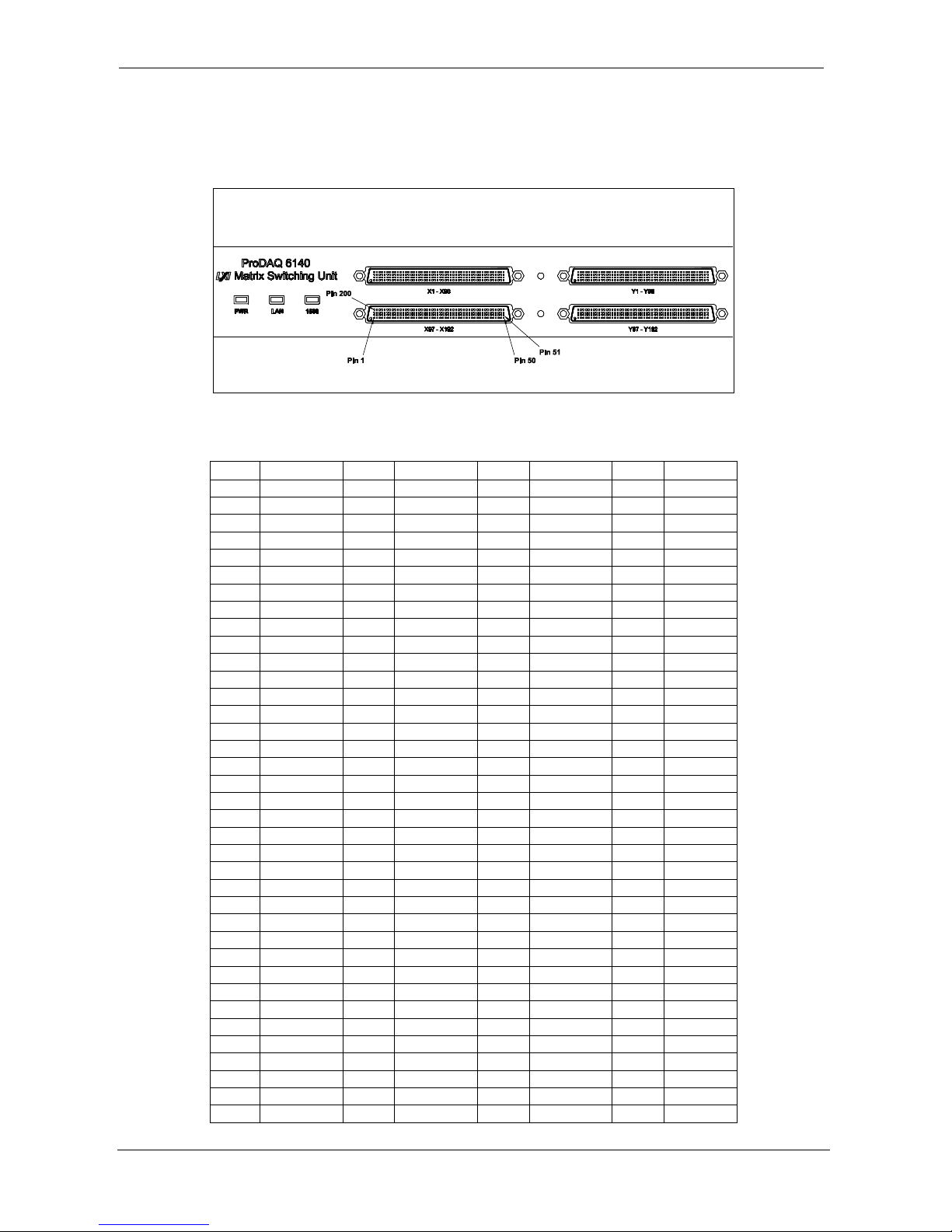
ProDAQ 6140 LXI Matrix Switching Unit User Manual
Page 49 of 56 Copyright © 2017, Bustec Production Ltd.
6. Connector Pin-outs
6.1. Signal channels X1 - X96 (200-pin Molex LFH connector)
Figure 55 - “X”/”Y” Signal Connectors Pin Number Assignment
Pin
Signal
Pin
Signal
Pin
Signal
Pin
Signal
1
-X1
100
-X25
101
-X49
200
-X73 2 +X1
99
+X25
102
+X49
199
+X73 3 -X2
98
-X26
103
-X50
198
-X74 4 +X2
97
+X26
104
+X50
197
+X74 5 -X3
96
-X27
105
-X51
196
-X75 6 +X3
95
+X27
106
+X51
195
+X75 7 -X4
94
-X28
107
-X52
194
-X76 8 +X4
93
+X28
108
+X52
193
+X76 9 -X5
92
-X29
109
-X53
192
-X77
10
+X5
91
+X29
110
+X53
191
+X77
11
-X6
90
-X30
111
-X54
190
-X78
12
+X6
89
+X30
112
+X54
189
+X78
13
-X7
88
-X31
113
-X55
188
-X79
14
+X7
87
+X31
114
+X55
187
+X79
15
-X8
86
-X32
115
-X56
186
-X80
16
+X8
85
+X32
116
+X56
185
+X80
17
-X9
84
-X33
117
-X57
184
-X81
18
+X9
83
+X33
118
+X57
183
+X81
19
-X10
82
-X34
119
-X58
182
-X82
20
+X10
81
+X34
120
+X58
181
+X82
21
-X11
80
-X35
121
-X59
180
-X83
22
+X11
79
+X35
122
+X59
179
+X83
23
-X12
78
-X36
123
-X60
178
-X84
24
+X12
77
+X36
124
+X60
177
+X84
25
-X13
76
-X37
125
-X61
176
-X85
26
+X13
75
+X37
126
+X61
175
+X85
27
-X14
74
-X38
127
-X62
174
-X86
28
+X14
73
+X38
128
+X62
173
+X86
29
-X15
72
-X39
129
-X63
172
-X87
30
+X15
71
+X39
130
+X63
171
+X87
31
-X16
70
-X40
131
-X64
170
-X88
32
+X16
69
+X40
132
+X64
169
+X88
33
-X17
68
-X41
133
-X65
168
-X89
34
+X17
67
+X41
134
+X65
167
+X89
35
-X18
66
-X42
135
-X66
166
-X90
36
+X18
65
+X42
136
+X66
165
+X90
37
-X19
64
-X43
137
-X67
164
-X91
Page 52

User Manual ProDAQ 6140 LXI Matrix Switching Unit
Copyright © 2017, Bustec Production Ltd. Page 50 of 56
Pin
Signal
Pin
Signal
Pin
Signal
Pin
Signal
38
+X19
63
+X43
138
+X67
163
+X91
39
-X20
62
-X44
139
-X68
162
-X92
40
+X20
61
+X44
140
+X68
161
+X92
41
-X21
60
-X45
141
-X69
160
-X93
42
+X21
59
+X45
142
+X69
159
+X93
43
-X22
58
-X46
143
-X70
158
-X94
44
+X22
57
+X46
144
+X70
157
+X94
45
-X23
56
-X47
145
-X71
156
-X95
46
+X23
55
+X47
146
+X71
155
+X95
47
-X24
54
-X48
147
-X72
154
-X96
48
+X24
53
+X48
148
+X72
153
+X96
49
NC
52
NC
149
NC
152
NC
50
GND
51
NC
150
NC
151
NC
6.2. Signal channels X97 - X192 (200-pin Molex LFH connector)
(ProDAQ 6140-AB version only)
Pin
Signal
Pin
Signal
Pin
Signal
Pin
Signal
1
-X97
100
-X121
101
-X145
200
-X169
2
+X97
99
+X121
102
+X145
199
+X169
3
-X98
98
-X122
103
-X146
198
-X170
4
+X98
97
+X122
104
+X146
197
+X170
5
-X99
96
-X123
105
-X147
196
-X171
6
+X99
95
+X123
106
+X147
195
+X171
7
-X100
94
-X124
107
-X148
194
-X172
8
+X100
93
+X124
108
+X148
193
+X172
9
-X101
92
-X125
109
-X149
192
-X173
10
+X101
91
+X125
110
+X149
191
+X173
11
-X102
90
-X126
111
-X150
190
-X174
12
+X102
89
+X126
112
+X150
189
+X174
13
-X103
88
-X127
113
-X151
188
-X175
14
+X103
87
+X127
114
+X151
187
+X175
15
-X104
86
-X128
115
-X152
186
-X176
16
+X104
85
+X128
116
+X152
185
+X176
17
-X105
84
-X129
117
-X153
184
-X177
18
+X105
83
+X129
118
+X153
183
+X177
19
-X106
82
-X130
119
-X154
182
-X178
20
+X106
81
+X130
120
+X154
181
+X178
21
-X107
80
-X131
121
-X155
180
-X179
22
+X107
79
+X131
122
+X155
179
+X179
23
-X108
78
-X132
123
-X156
178
-X180
24
+X108
77
+X132
124
+X156
177
+X180
25
-X109
76
-X133
125
-X157
176
-X181
26
+X109
75
+X133
126
+X157
175
+X181
27
-X110
74
-X134
127
-X158
174
-X182
28
+X110
73
+X134
128
+X158
173
+X182
29
-X111
72
-X135
129
-X159
172
-X183
30
+X111
71
+X135
130
+X159
171
+X183
31
-X112
70
-X136
131
-X160
170
-X184
32
+X112
69
+X136
132
+X160
169
+X184
33
-X113
68
-X137
133
-X161
168
-X185
34
+X113
67
+X137
134
+X161
167
+X185
35
-X114
66
-X138
135
-X162
166
-X186
36
+X114
65
+X138
136
+X162
165
+X186
37
-X115
64
-X139
137
-X163
164
-X187
Page 53

ProDAQ 6140 LXI Matrix Switching Unit User Manual
Page 51 of 56 Copyright © 2017, Bustec Production Ltd.
Pin
Signal
Pin
Signal
Pin
Signal
Pin
Signal
38
+X115
63
+X139
138
+X163
163
+X187
39
-X116
62
-X140
139
-X164
162
-X188
40
+X116
61
+X140
140
+X164
161
+X188
41
-X117
60
-X141
141
-X165
160
-X189
42
+X117
59
+X141
142
+X165
159
+X189
43
-X118
58
-X142
143
-X166
158
-X190
44
+X118
57
+X142
144
+X166
157
+X190
45
-X119
56
-X143
145
-X167
156
-X191
46
+X119
55
+X143
146
+X167
155
+X191
47
-X120
54
-X144
147
-X168
154
-X192
48
+X120
53
+X144
148
+X168
153
+X192
49
NC
52
NC
149
NC
152
NC
50
GND
51
NC
150
NC
151
NC
6.3. Signal channels Y1 - Y96 (200-pin Molex LFH connector)
Pin
Signal
Pin
Signal
Pin
Signal
Pin
Signal
1
-Y1
100
-Y25
101
-Y49
200
-Y73 2 +Y1
99
+Y25
102
+Y49
199
+Y73 3 -Y2
98
-Y26
103
-Y50
198
-Y74 4 +Y2
97
+Y26
104
+Y50
197
+Y74 5 -Y3
96
-Y27
105
-Y51
196
-Y75 6 +Y3
95
+Y27
106
+Y51
195
+Y75 7 -Y4
94
-Y28
107
-Y52
194
-Y76 8 +Y4
93
+Y28
108
+Y52
193
+Y76 9 -Y5
92
-Y29
109
-Y53
192
-Y77
10
+Y5
91
+Y29
110
+Y53
191
+Y77
11
-Y6
90
-Y30
111
-Y54
190
-Y78
12
+Y6
89
+Y30
112
+Y54
189
+Y78
13
-Y7
88
-Y31
113
-Y55
188
-Y79
14
+Y7
87
+Y31
114
+Y55
187
+Y79
15
-Y8
86
-Y32
115
-Y56
186
-Y80
16
+Y8
85
+Y32
116
+Y56
185
+Y80
17
-Y9
84
-Y33
117
-Y57
184
-Y81
18
+Y9
83
+Y33
118
+Y57
183
+Y81
19
-Y10
82
-Y34
119
-Y58
182
-Y82
20
+Y10
81
+Y34
120
+Y58
181
+Y82
21
-Y11
80
-Y35
121
-Y59
180
-Y83
22
+Y11
79
+Y35
122
+Y59
179
+Y83
23
-Y12
78
-Y36
123
-Y60
178
-Y84
24
+Y12
77
+Y36
124
+Y60
177
+Y84
25
-Y13
76
-Y37
125
-Y61
176
-Y85
26
+Y13
75
+Y37
126
+Y61
175
+Y85
27
-Y14
74
-Y38
127
-Y62
174
-Y86
28
+Y14
73
+Y38
128
+Y62
173
+Y86
29
-Y15
72
-Y39
129
-Y63
172
-Y87
30
+Y15
71
+Y39
130
+Y63
171
+Y87
31
-Y16
70
-Y40
131
-Y64
170
-Y88
32
+Y16
69
+Y40
132
+Y64
169
+Y88
33
-Y17
68
-Y41
133
-Y65
168
-Y89
34
+Y17
67
+Y41
134
+Y65
167
+Y89
35
-Y18
66
-Y42
135
-Y66
166
-Y90
36
+Y18
65
+Y42
136
+Y66
165
+Y90
37
-Y19
64
-Y43
137
-Y67
164
-Y91
38
+Y19
63
+Y43
138
+Y67
163
+Y91
39
-Y20
62
-Y44
139
-Y68
162
-Y92
Page 54

User Manual ProDAQ 6140 LXI Matrix Switching Unit
Copyright © 2017, Bustec Production Ltd. Page 52 of 56
Pin
Signal
Pin
Signal
Pin
Signal
Pin
Signal
40
+Y20
61
+Y44
140
+Y68
161
+Y92
41
-Y21
60
-Y45
141
-Y69
160
-Y93
42
+Y21
59
+Y45
142
+Y69
159
+Y93
43
-Y22
58
-Y46
143
-Y70
158
-Y94
44
+Y22
57
+Y46
144
+Y70
157
+Y94
45
-Y23
56
-Y47
145
-Y71
156
-Y95
46
+Y23
55
+Y47
146
+Y71
155
+Y95
47
-Y24
54
-Y48
147
-Y72
154
-Y96
48
+Y24
53
+Y48
148
+Y72
153
+Y96
49
NC
52
NC
149
NC
152
NC
50
GND
51
NC
150
NC
151
NC
6.4. Signal channels Y97 - Y192 (200-pin Molex LFH connector)
(ProDAQ 6140-AB version only)
Pin
Signal
Pin
Signal
Pin
Signal
Pin
Signal
1
-Y97
100
-Y121
101
-Y145
200
-Y169
2
+Y97
99
+Y121
102
+Y145
199
+Y169
3
-Y98
98
-Y122
103
-Y146
198
-Y170
4
+Y98
97
+Y122
104
+Y146
197
+Y170
5
-Y99
96
-Y123
105
-Y147
196
-Y171
6
+Y99
95
+Y123
106
+Y147
195
+Y171
7
-Y100
94
-Y124
107
-Y148
194
-Y172
8
+Y100
93
+Y124
108
+Y148
193
+Y172
9
-Y101
92
-Y125
109
-Y149
192
-Y173
10
+Y101
91
+Y125
110
+Y149
191
+Y173
11
-Y102
90
-Y126
111
-Y150
190
-Y174
12
+Y102
89
+Y126
112
+Y150
189
+Y174
13
-Y103
88
-Y127
113
-Y151
188
-Y175
14
+Y103
87
+Y127
114
+Y151
187
+Y175
15
-Y104
86
-Y128
115
-Y152
186
-Y176
16
+Y104
85
+Y128
116
+Y152
185
+Y176
17
-Y105
84
-Y129
117
-Y153
184
-Y177
18
+Y105
83
+Y129
118
+Y153
183
+Y177
19
-Y106
82
-Y130
119
-Y154
182
-Y178
20
+Y106
81
+Y130
120
+Y154
181
+Y178
21
-Y107
80
-Y131
121
-Y155
180
-Y179
22
+Y107
79
+Y131
122
+Y155
179
+Y179
23
-Y108
78
-Y132
123
-Y156
178
-Y180
24
+Y108
77
+Y132
124
+Y156
177
+Y180
25
-Y109
76
-Y133
125
-Y157
176
-Y181
26
+Y109
75
+Y133
126
+Y157
175
+Y181
27
-Y110
74
-Y134
127
-Y158
174
-Y182
28
+Y110
73
+Y134
128
+Y158
173
+Y182
29
-Y111
72
-Y135
129
-Y159
172
-Y183
30
+Y111
71
+Y135
130
+Y159
171
+Y183
31
-Y112
70
-Y136
131
-Y160
170
-Y184
32
+Y112
69
+Y136
132
+Y160
169
+Y184
33
-Y113
68
-Y137
133
-Y161
168
-Y185
34
+Y113
67
+Y137
134
+Y161
167
+Y185
35
-Y114
66
-Y138
135
-Y162
166
-Y186
36
+Y114
65
+Y138
136
+Y162
165
+Y186
37
-Y115
64
-Y139
137
-Y163
164
-Y187
38
+Y115
63
+Y139
138
+Y163
163
+Y187
39
-Y116
62
-Y140
139
-Y164
162
-Y188
Page 55
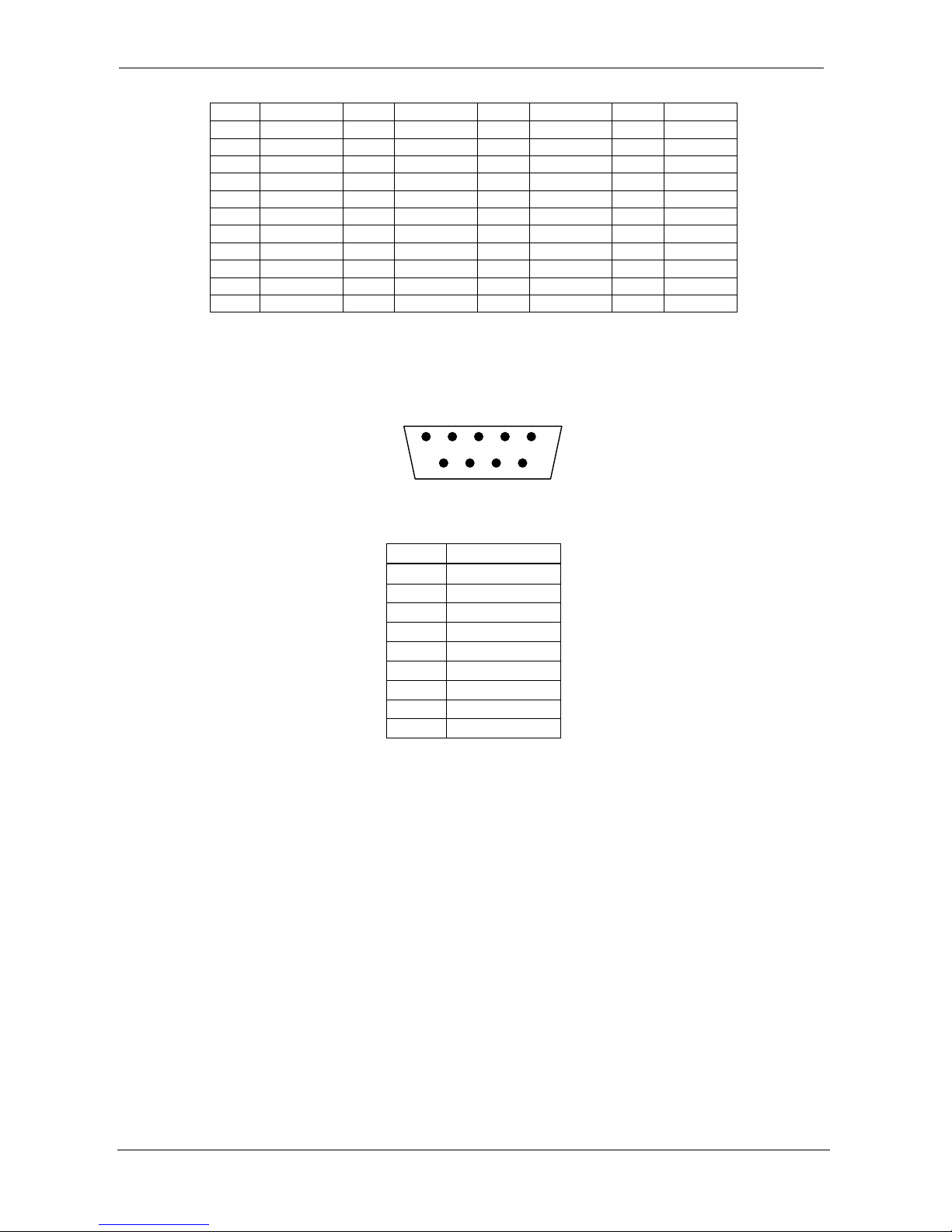
ProDAQ 6140 LXI Matrix Switching Unit User Manual
Page 53 of 56 Copyright © 2017, Bustec Production Ltd.
Pin
Signal
Pin
Signal
Pin
Signal
Pin
Signal
40
+Y116
61
+Y140
140
+Y164
161
+Y188
41
-Y117
60
-Y141
141
-Y165
160
-Y189
42
+Y117
59
+Y141
142
+Y165
159
+Y189
43
-Y118
58
-Y142
143
-Y166
158
-Y190
44
+Y118
57
+Y142
144
+Y166
157
+Y190
45
-Y119
56
-Y143
145
-Y167
156
-Y191
46
+Y119
55
+Y143
146
+Y167
155
+Y191
47
-Y120
54
-Y144
147
-Y168
154
-Y192
48
+Y120
53
+Y144
148
+Y168
153
+Y192
49
NC
52
NC
149
NC
152
NC
50
GND
51
NC
150
NC
151
NC
6.5. Rear Bus Daisy-Chaining
9-pin D-Sub receptacle (female) connectors:
Figure 6-56 Rear panel view of Bus Daisy Chain connector
Pin
Signal
1
GND
2
+B 3 -B 4 +C 5 -C 6 -A 7 +A 8 -D 9 +D
1
Page 56

 Loading...