

Page 1
USER MANUAL
ProDAQ Data Acquisition Function Cards
ProDAQ 3424 8-Channel, 24-Bit,
Sigma-Delta ADC Function Card
PUBLICATION NUMBER: 3424-XX-UM-0010
Copyright, © 2014, Bustec Production, Ltd.
Bustec Production, Ltd.
Bustec House, Shannon Business Park, Shannon, Co. Clare, Ireland
Tel: +353 (0) 61 707100, FAX: +353 (0) 61 707106
Page 2

PROPRIETARY NOTICE
This document and the technical data herein disclosed, are proprietary to Bustec
Production Ltd., and shall not, without express written permission of Bustec
Production Ltd, be used, in whole or in part to solicit quotations from a competitive
source or used for manufacture by anyone other than Bustec Production Ltd. The
information herein has been developed at private expense, and may only be used for
operation and maintenance reference purposes or for purposes of engineering
evaluation and incorporation into technical specifications and other documents,
which specify procurement of products from Bustec Production Ltd.. This document
is subject to change without further notification. Bustec Production Ltd. Reserve the
right to change both the hardware and software described herein.
Page 3

ProDAQ 3424 Function Card User Manual 3424-XX-UM
Copyright, 1998-2005 Bustec Production Ltd. Page 3 of 56
Table of Contents
1. INTRODUCTION ........................................................................................................... 7
2. INSTALLATION ............................................................................................................ 8
2.1. Unpacking and Inspection .................................................................................... 8
2.2. Reshipment Instructions ....................................................................................... 8
2.3. Preparing the ProDAQ Module ............................................................................. 9
2.4. Installing a ProDAQ Function Card ..................................................................... 10
2.5. Removing a ProDAQ Function Card ................................................................... 12
3. THEORY OF OPERATION ......................................................................................... 13
3.1. Analog Front-End Circuitry ................................................................................. 13
3.1.1. Analog Front-End general description .......................................................... 13
3.1.2. ICP sensor conditioning ............................................................................... 14
3.1.3. TEDS reader interface ................................................................................. 14
3.2. Digital Front-End Circuitry .................................................................................. 15
3.2.1. Motherboard function card interface ........................................................ 15
3.2.2. Front panel digital signals ............................................................................ 15
3.2.3. Local synchronization link ............................................................................ 16
3.3. Data Acquisition ................................................................................................. 16
3.3.1. Data Acquisition modes ............................................................................... 17
3.3.2. Data storage and readout ............................................................................ 18
3.3.3. FIR filters and decimation ............................................................................ 19
3.3.4. Sampling settings ......................................................................................... 19
3.3.5. Input Trigger ................................................................................................ 21
3.3.6. Output Trigger, Direct Interrupt and Direct Error .......................................... 22
3.3.7. Analog Trigger ............................................................................................. 24
3.3.8. Analog channel correction............................................................................ 25
3.3.9. Multiple cards configuration ......................................................................... 25
4. FRONT PANEL CONNECTORS ................................ ................................ ................. 29
5. REGISTER DESCRIPTION ......................................................................................... 31
5.1. FCID – Function Card ID Register ...................................................................... 32
5.2. FCVER – Function Card Version Register.......................................................... 32
5.3. FCCRS – Function Card Control and Status Register ........................................ 32
5.4. MODE1 – Mode 1 Register................................................................................. 34
5.5. MODE2 – Mode 2 Register................................................................................. 35
5.6. OTRI_CFG – Output Trigger Configuration Register .......................................... 38
5.7. ITRI_CFG – Input Trigger Configuration Register .............................................. 40
5.8. FIFO_CTRL – FIFO Control Register ................................................................. 41
5.9. FIFO_WRL – FIFO Write Low Register.............................................................. 42
5.10. FIFO_WRH – FIFO Write High Register ............................................................ 43
5.11. PRET_NOS – Pre-Trigger Number of Scans Register ....................................... 43
5.12. POSTT_NOSL – Post-Trigger Number of Scans Low Register .......................... 43
5.13. POSTT_NOSH – Post Trigger Number of Scans High Register ......................... 43
Page 4

3424-XX-UM ProDAQ 3424 Function Card User Manual
Page 4 of 56 Copyright, 1998-2005 Bustec Production Ltd.
5.14. AT_THR_SIGERR – Analog Trigger Threshold / Signal Error Register .............. 44
5.15. AT_CTRL – Analog Trigger Control Register ..................................................... 44
5.16. CHNxCFG – Channel x Configuration Register .................................................. 45
5.17. DDS_WX – DDS Word Register ........................................................................ 46
5.18. DAC_DATA – DAC Data Register ...................................................................... 47
5.19. DAC_ADDR – DAC Address Register ................................................................ 47
5.20. TEDS_ACC – TEDS Access Register ................................................................ 48
5.21. GCOEFL – Gain correction coefficient write register, bits 15..0.......................... 49
5.22. GCOEFH – Gain correction coefficient write register, bits 23..16 and address .. 49
5.23. EPD – EEPROM Data Register .......................................................................... 49
5.24. EPC – EEPROM Control Register ...................................................................... 50
5.25. FCSUB – Function Card Sub-Type Register ...................................................... 51
5.26. FCSERH – Function Card Serial Number High Register .................................... 51
5.27. FCSERL – Function Card Serial Number Low Register ..................................... 52
6. TECHNICAL SPECIFICATION ................................................................................... 53
7. THE VXIPLUG&PLAY DRIVER .................................................................................. 55
8. PROGRAMMING THE PRODAQ 3424 ....................................................................... 55
Page 5

ProDAQ 3424 Function Card User Manual 3424-XX-UM
Copyright, 1998-2005 Bustec Production Ltd. Page 5 of 56
Table of figures
Figure 1 – Removing the ProDAQ module cover ................................................................. 9
Figure 2 – The ProDAQ module assembly ......................................................................... 11
Figure 3 – Simplified block diagram of 3424 function card .................................................. 13
Figure 4 – Configuration of analog front-end circuitry (single channel) of the 3424 card ..... 14
Figure 5 – ADC clock configuration..................................................................................... 20
Figure 6 – Input Trigger configuration scheme ................................................................... 21
Figure 7 – Examples of the Input Trigger configuration ...................................................... 22
Figure 8 – Output Trigger, Direct Interrupt and Direct Error configuration scheme ............. 23
Figure 9 – Analog Trigger modes explanation .................................................................... 24
Figure 10 – The series of the pulses on SYNC/TRIG signal ............................................... 27
Figure 11 – Multiple boards link scheme ............................................................................. 28
Figure 12 – Front panel connectors layout .......................................................................... 29
Page 6

3424-XX-UM ProDAQ 3424 Function Card User Manual
Page 6 of 56 Copyright, 1998-2005 Bustec Production Ltd.
Reference Documents
Title
Number
ProDAQ 3120 User Manual
3120-XX-UM
ProDAQ 3150 User Manual
3150-XX-UM
Glossary
ADC
:
Analog-to-Digital Converter
CRD
:
Current Regulator Diode
DA
:
Data Acquisition
DAC
:
Digital-to-Analog Converter
DDS
:
Direct Digital Synthesis
DTC
:
Discharge Time Constant
ECL
:
Emitter-Coupled Logic
FIR
:
Finite Impulse Response digital filter
FPGA
:
Field Programmable Gate Array
H
:
State of the bit(s) defined by hardware (in register description)
ICP
:
Integrated Circuit Piezoelectric
LED
:
Light Emitting Diode
LVDS
:
Low Voltage Differential Signal(ing)
PCB
:
Printed Circuit Board
PGA
:
Programmable Gain Amplifier
PLL
:
Phase-Locked Loop
RO
:
Read-only access to register
R/W
:
Read/Write access to register
R/WSC
:
Read/Write access to register, Self-Clear after operation finished
TEDS
:
Transducer Electronic Data Sheet
VREF
:
Voltage Reference
VXI
:
VME eXtensions for Instrumentation
WO
:
Write-only access to register
Page 7

ProDAQ 3424 Function Card User Manual 3424-XX-UM
Copyright, 1998-2005 Bustec Production Ltd. Page 7 of 56
1. Introduction
The ProDAQ 3424 function card is an 8-channel, 24-bit Sigma-Delta Analog-to-Digital converter
function card. It is an add-on card to use together with ProDAQ 3120 and 3150 motherboards.
It provides the following features:
8 analog channels of simultaneous sampling with 24-bit resolution
Differential and single-ended analog input configuration
Max. Input Range 10V
Programmable gains of 1, 2, 5, 10, 20, 50, 100, 200, 500 and 1000
DC/AC coupling
Variable sampling clock with a maximum 216 kHz output word rate
Software selectable x10 and x100 decimation for output word rate as low as 200 Hz
On-board FIFO of 64 ksamples
Possibility of multiple 3424 cards synchronization (Master/Slave approach)
ICP® sensor conditioning
IEEE 1451.4 (TEDS) Smart Transducer Interface support
Page 8

3424-XX-UM ProDAQ 3424 Function Card User Manual
Page 8 of 56 Copyright, 1998-2005 Bustec Production Ltd.
2. Installation
2.1. Unpacking and Inspection
The ProDAQ module is shipped in an antistatic package to prevent any damage from electrostatic
discharge (ESD). Proper ESD handling procedures must always be used when packing, unpacking
or installing any ProDAQ module, ProDAQ plug-in module or ProDAQ function card:
Ground yourself via a grounding strap or similar, e.g. by holding to a grounded object.
Discharge the package by touching it to a grounded object, e.g. a metal part of your VXIbus
chassis, before removing the module from the package.
Remove the ProDAQ module from its carton, preserving the factory packaging as much as
possible.
Inspect the ProDAQ module for any defect or damage. Immediately notify the carrier if any
damage is apparent.
2.2. Reshipment Instructions
Use the original packing material when returning a ProDAQ module to Bustec Production Ltd. for
calibration or servicing. The original shipping carton and the instrument's plastic foam will provide
the necessary support for safe reshipment.
If the original anti-static packing material is unavailable, wrap the ProDAQ module in anti-static
plastic sheeting and use plastic spray foam to surround and protect the instrument. Reship in either
the original or new shipping carton.
Page 9
ProDAQ 3424 Function Card User Manual 3424-XX-UM
Copyright, 1998-2005 Bustec Production Ltd. Page 9 of 56
2.3. Preparing the ProDAQ Module
To install a ProDAQ function card into one of the ProDAQ motherboards, you need to remove the
module’s top cover:
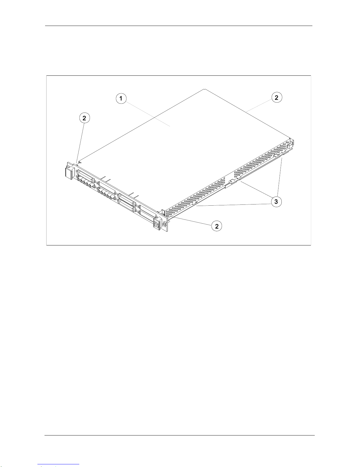
1 - Module Cover
2 - Cover Screws
3 - Cover Hooks
Figure 1 – Removing the ProDAQ module cover
To remove the top cover, remove the one countersunk screw in the back and the two panhead
screws towards the front panel (), that hold the cover in place. Remove the cover by sliding it out
of its position towards the VXIbus connectors and up. Take special care about the hooks ()
holding it in place. Try not to lift the cover straight up. See Figure 1 for the location of the screws.
To re-install the cover, slide it back into its position by placing the small hooks over their holes and
moving the cover down and forward. Secure the top cover using two panhead screws and one
countersunk screw ().
Page 10

3424-XX-UM ProDAQ 3424 Function Card User Manual
Page 10 of 56 Copyright, 1998-2005 Bustec Production Ltd.
2.4. Installing a ProDAQ Function Card
The single-width ProDAQ function cards are arranged inside the ProDAQ module in four stacks of
two cards each. The double-width ProDAQ function cards are arranged inside the ProDAQ module
in two stacks of two cards each. The function cards are mounted face down, e.g. the front-panel
connectors as well as the motherboard connectors are underneath the PCB. Single-width and
double-width ProDAQ function cards can be mixed in the ProDAQ module. The 3424 function card
is a double-width card.
To install a single-width ProDAQ function card in any of the possible positions, use the following
procedure (See Figure 2 for reference):
Remove the top cover of the module as described earlier in this chapter (Fig. 2, Pos. 1).
Remove all screws on the front-panel holding installed function cards or double filler
panels in place (Fig. 2, Pos. 2). Screws holding single filler panels don't need to be
removed.
Remove the two panhead screws that mount the front panel to the modules bottom cover
(Fig. 2, Pos. 6).
Please take special care of the module handles and the rings (Fig. 2, Pos. 3 and 4), which
are also fixed by those screws. The mounting angle (Fig. 2, Pos. 5) stays fixed to the front
panel.
Remove the front panel by moving it forward carefully so as to avoid bending the installed
function cards.
Choose the stack and position (lower or upper) where you want to mount the function
card. If the stack, in which the function card should be installed, is covered by a double
filler panel, you have to remove it before installing the function card.
Remove the three 2.5mm panhead screws and the crinkle washers from the stack's
standoffs (Fig. 2, Pos. 9 and 10 for example).
If you want to install a function card in the upper position of a stack without having a
function card in the lower position, you need to mount both spacers (Fig. 3, Pos. 11) on
each standoff. If the stack is already populated with a function card in the lower position,
mount only the bigger spacer (Fig. 2, Pos. 8) onto each standoff.
Place a bayonet (supplied) on each standoff. Align the function card over these and slide
carefully down. The function card should be held parallel to the modules bottom cover all
the time during its way down.
Fix the function card by mounting the three 2.5mm panhead screws and the crinkle
washers onto each standoff. If you install a function card in the lower position of a stack,
you need first to mount both spacers (Fig. 2, Pos. 11) onto each standoff.
Re-mount the modules front-panel. If there is only one function card mounted in a stack,
cover the remaining opening in the front panel by a single filler panel.
Re-mount the modules top cover.
Adjust the procedure respectively for a double-width ProDAQ function card.
Page 11
ProDAQ 3424 Function Card User Manual 3424-XX-UM
Copyright, 1998-2005 Bustec Production Ltd. Page 11 of 56
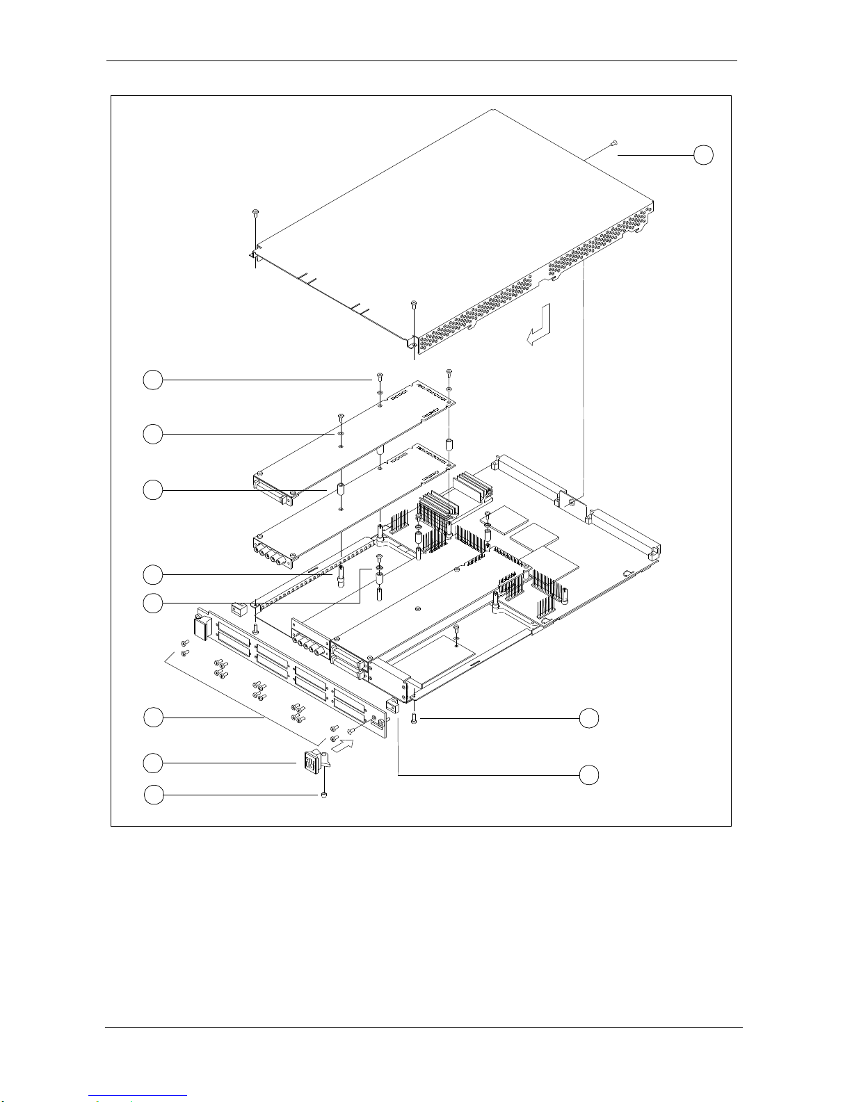
2
10
9
8 7 11
1
3 5 6
4
1 - 2.5mm Panhead Screws
2 - 2.5mm Panhead Screws
3 - Module Handle
4 - Ring
5 - Mounting Angle
6 - 2.5mm Panhead Screws
7 - Standoff
8 - Spacer
9 - Crinkle Washer
10 - 2.5mm Panhead Screw
11 - 2mm Spacer
Figure 2 – The ProDAQ module assembly
Page 12

3424-XX-UM ProDAQ 3424 Function Card User Manual
Page 12 of 56 Copyright, 1998-2005 Bustec Production Ltd.
2.5. Removing a ProDAQ Function Card
Removing a ProDAQ function card is exactly the reverse operation then installing it. After removing
the top cover and the front panel as described previously, remove the three roundhead screws that
fix the function card(s) on the standoffs.
Take special care when removing the function card(s) not to bend the motherboard connectors.
After removing the function card(s), install the correct combination of spacers on the standoffs. If a
stack is populated with only one function card, each of the standoffs needs to be mounted with both
spacers to cover the distance between the cards as well as the PCB thickness of the missing card.
If a stack is populated with two function cards, only the bigger spacer must be mounted.
Fix any remaining function cards again by mounting the three panhead screws on the standoffs, remount the front panel and the modules cover.
Page 13
ProDAQ 3424 Function Card User Manual 3424-XX-UM
Copyright, 1998-2005 Bustec Production Ltd. Page 13 of 56
3. Theory of Operation
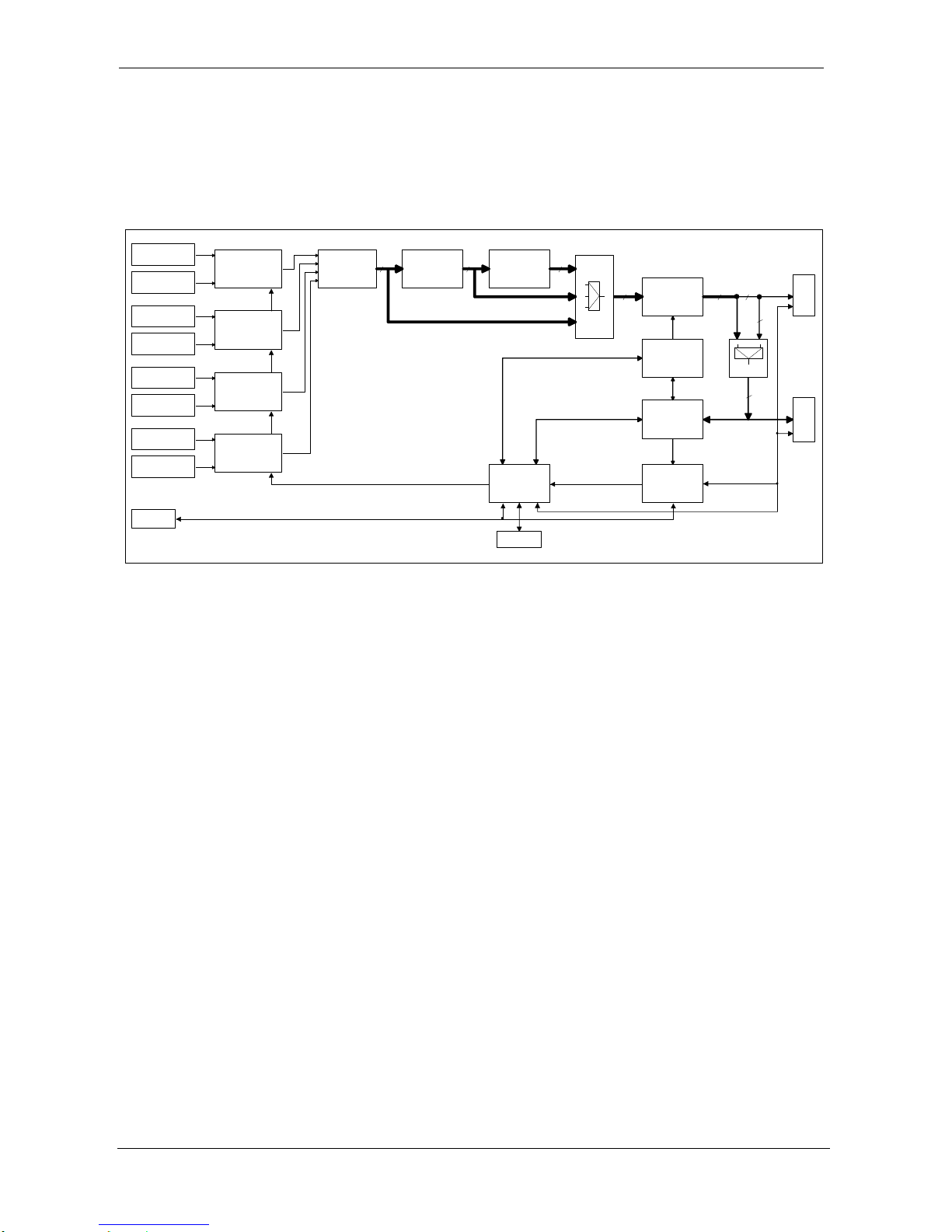
A simplified block diagram of 3424 function card is shown on Figure 3.
A brief description of the most important blocks and available functionality follows.
Front-End Circuitry
Channel #1
Front-End Circuitry
Channel #2
24-bit ADC
2 channels
24-bit ADC
2 channels
24-bit ADC
2 channels
24-bit ADC
2 channels
Serial to Parallel
FIFO
64kSamples
24
DA control
Internal Registers
Stack B
Stack A
24168
MUX
8
Clock Generation
(PLL and DDS)
Front Panel
SYNC I/O
Local
SYNC I/O
Front-End Circuitry
Channel #3
Front-End Circuitry
Channel #4
Front-End Circuitry
Channel #5
Front-End Circuitry
Channel #6
Front-End Circuitry
Channel #7
Front-End Circuitry
Channel #8
FIR Filter and
Decimation 10x
Stage #1
FIR Filter and
Decimation 10x
Stage #2
MUX
24
24
Synchronization
System
Acquisition Clock and Reset
24
Figure 3 – Simplified block diagram of 3424 function card
3.1. Analog Front-End Circuitry
3.1.1. Analog Front-End general description
The front-end of the 3424 card gives the user a flexible solution for a wide range of applications. It
is designed to accept either single-ended or differential input signals with a bandwidth of up to
100 kHz. The input signal can be either AC or DC coupled. The full-scale range of the card is
10V. For higher input voltage levels (up to 100V maximum), it is possible to have a factory set
attenuator stage.
As well as the standard sensor interface, the card includes the possibility of direct interfacing with
ICP sensors and accessing the sensors’ Transducer Electronic Data Sheet (TEDS) information.
The constant current power source is provided on the board. A LED lights when ICP is selected
and drawing current, so it simplifies system setup and detection of open circuits.
For calibration purposes, the input of every channel can be connected to the voltage output of the
high-precision ProDAQ 3201 voltage reference board by switching with relays. This voltage
reference board can be programmed to 0V (ground connection). The card has built-in input
overvoltage protection diodes designed to prevent damage being caused to the input
programmable gain amplifier (PGA) stage.
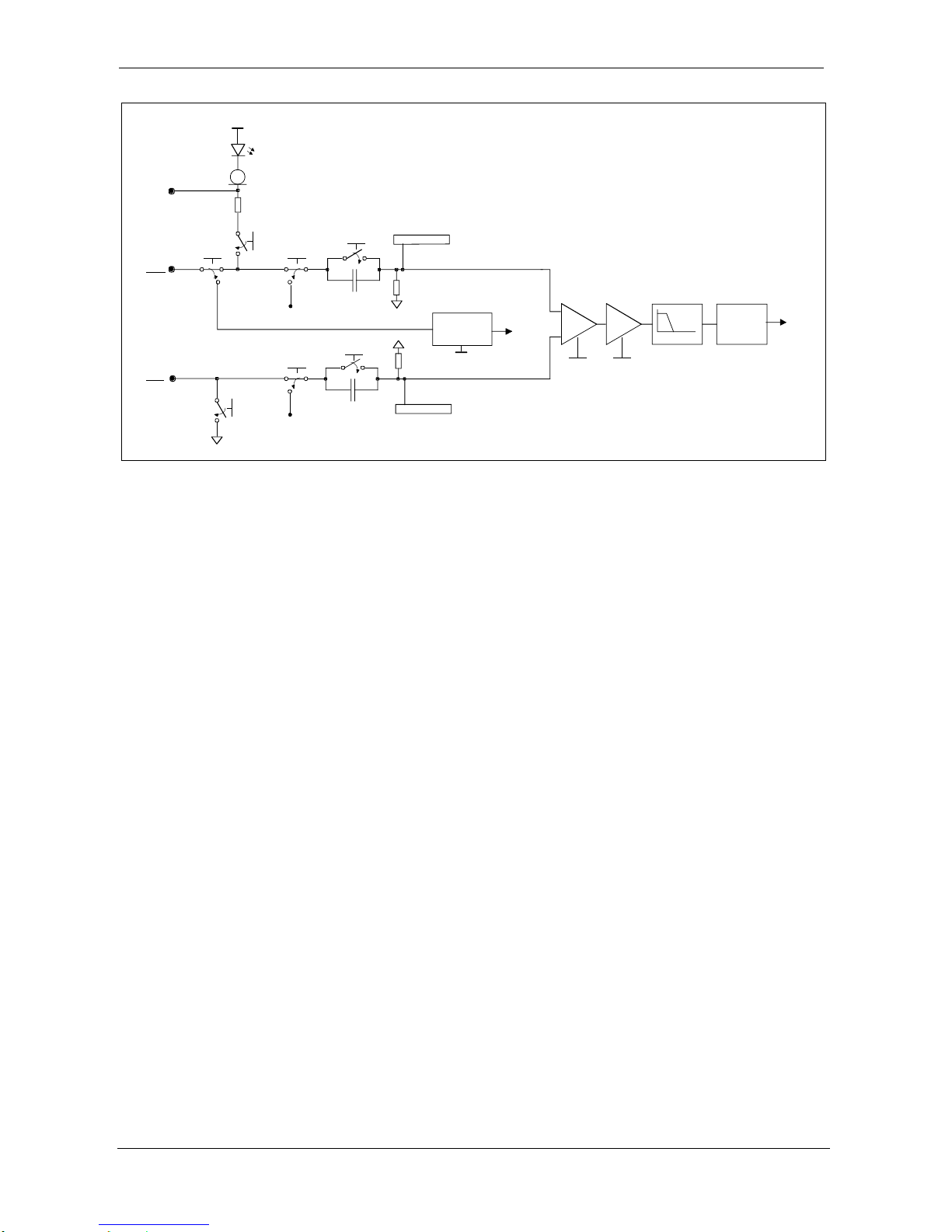
The input signal goes to the PGA stage. The possible gain values are: 1,2,5,10,20,50,100,200,500
and 1000, thus providing immense flexibility for the user. The output of the gain stage is fed to a 4
pole fixed Butterworth anti-aliasing analog input filter which allows for output sample rates in the
range of 20 kHz to 216 kHz without violating Nyquist theorem (sampling rates as low as 200 Hz
can be achieved with implemented in FPGA digital filters and decimation stages). The output of the
filter after offset correction is fed to the differential input of the ADC. Single channel configuration of
the 3424 card front-end circuitry is shown on Figure 4.
Page 14
3424-XX-UM ProDAQ 3424 Function Card User Manual
Page 14 of 56 Copyright, 1998-2005 Bustec Production Ltd.
CHN+
Input protection
+
24V
10M
10M
Input protection
1uF
1uF
PGA 1
Low PassFilter
24-bit
ADC
TEDS_ON
ICP_ON
POS_CPL
NEG_CPL
GAIN1SEL[1:0]
To FPGA
PGA 2
GAIN2SEL[1:0]
VREFGND_EN
VREFGND_EN
VREF-/GND
for calibration
NEG_GND
TEDS reader
circuitry
-5V
VREF+/GND
for calibration
To FPGA
SENSE ICP
Current
regulator
diode
CHN-
Figure 4 – Configuration of analog front-end circuitry (single channel) of the 3424 card
3.1.2. ICP sensor conditioning
An ICP sensor requires a constant current bias. This is generated using a Current Regulator Diode
(CRD) connected to +24V. For a +24V supply the sensor output will then bias at about +10V with
10V max swing. The accuracy of the current source is not critical although it needs to be constant.
At high frequencies ICP sensors require higher current in order to operate with the same cable
length. The maximum frequency is proportional to the current & inversely proportional to the cable
capacitance (i.e. cable length). Thus, the 3424 is fitted with one 4.7mA CRD as a standard with the
second one fitted upon request.
The ICP excitation current is switched to the ICP sensor with a relay. If ICP is selected and the ICP
excitation current is flowing then a LED lights to indicate this. Because it often happens that the
sensor do not connect directly to the VXI module, but to some external signal conditioning unit or
breakout board, it is desired that the ICP current can be indicated in this remote location. This can
be achieved with additional SENSE ICP signal routed to the front panel SCSI connector.
Comparing voltage drop across 22sense resistor with a reference voltage level allows switching
on a LED diode in the signal conditioning unit when the ICP excitation current is really flowing.
Other solutions, like digital control of a remote LED, don’t allow for detection of open circuit in this
case.
The positive output of the ICP sensor connects to the positive input of the channel. During normal
operation, the signal is AC coupled in order to remove the DC bias. The negative side of the ICP
sensor needs to be connected to the same GND as the +24V supply. For the 3424 card this is
achieved with means of a relay that can switch the negative side to GND for single-ended sensors.
At low frequencies there are two important considerations. One is the Discharge Time Constant
(DTC) of the sensor. This varies from sensor to sensor and can be from milliseconds to several
hundreds of seconds. The user needs to consider this effect when measuring signals.
The second low frequency effect is the time constant of the coupling circuit when used in AC
coupling mode. A 10MΩ resistor with a 1μF coupling capacitor requires 50 seconds to reach 5RC
(5 time constants), required for drift free stable operation.
3.1.3. TEDS reader interface
Page 15

ProDAQ 3424 Function Card User Manual 3424-XX-UM
Copyright, 1998-2005 Bustec Production Ltd. Page 15 of 56
Transducer Electronic Data Sheet (TEDS), is a nonvolatile memory within a sensor that is utilized
for storing information about that sensor. The manufacturer of the sensor deposits, into this
memory, initial information such as manufacturer name, sensor type, model number, serial
number, and calibration data. Memory space allocation permits the user to add additional
information such as channel ID, location, position, direction, tag number, etc. The protocols and
formats of the data are defined by IEEE P1451.4 standard.
The sensor operates in a “mixed mode”, i.e. analog or digital fashion. In the digital mode, the
information stored in memory is downloaded. In the analog mode, the sensor functions normally, as
a measurement device. A suitable TEDS signal conditioner is used to access the memory digitally,
over the same wires ordinarily used for analog measurement signal transmission.
The 3424 card has a common TEDS reader interface circuitry for all eight channels. A relay in the
positive input of the channel is used to connect it to a TEDS reader. Care should be taken not to
write the software in the way that connects more than one channel to the TEDS reader at a time.
3.2. Digital Front-End Circuitry
3.2.1. Motherboard function card interface
This is the interface that is used to exchange data between motherboard and function card.
Detailed description of this interface is beyond the scope of this manual. However, a short
explanation is needed regarding names used. Following names appear interchangeably throughout
document:
Trigger input, Stack A nTRIGI_A
Trigger input, Stack B nTRIGI_B
Trigger output, Stack A nTRIGO_A
Trigger output, Stack B nTRIGO_B
Direct Interrupt, Stack A nDI_A
Direct Interrupt, Stack B nDI_B
Direct Error nDE
The shorter names are used on the drawings for better clarity. The small “n” in the beginning of the
name indicates that the signal is active low level.
3.2.2. Front panel digital signals
There are three SMB type connectors on the front panel of the card.
The connectors are:
FPSYNC_IO, bi-directional Input/Output for distribution of SYNC/TRIG signals in TTL
standard. When configured as an input, the active polarity is software selectable. When
configured as an output, it is always active low level.
FPCLK_IN, clock input in ECL standard, with software programmable termination (50to –
2V)
FPCLK_OUT, clock output in ECL standard
Care should be taken while making cable connections between multiple cards. First of all, it is
important that the cables used for clock and SYNC/TRIG signals are of the same length. Big
difference in cable length could lead to a change in their phase relationship. As a result, the Master
Page 16

3424-XX-UM ProDAQ 3424 Function Card User Manual
Page 16 of 56 Copyright, 1998-2005 Bustec Production Ltd.
and Slave cards could sample analog signal on different clock edges. Cables should be kept as
short as possible. This is important when phase performance is critical. It is worth to remember that
the cable adds approximately 6 ns delay per meter. Also it is important that the optimal way of connecting fast
digital signals in respect for their integrity is point-to-point connection. If it is impossible, the stubs should be
kept as short as possible. Note that the termination on the ECL signal should be enabled only on the last
receiver in the chain. To avoid stubs, clock forwarding mechanism was implemented on 3424 card. It works
in the way that the card that receives clock on the terminated FPCLK_IN input simultaneously outputs it on
FPCLK_OUT output. This output can be connected to the input of another 3424 card, and so on. Clock
forwading requires setting bits FPCLKO_SEL in MODE2 register to ‘11’.
3.2.3. Local synchronization link
There is possibility of synchronization of multiple 3424 cards in the same VXI module with local
cable connections between them (local synchronization link). This makes possible to distribute
clock and SYNC/TRIG signals without propagating them through switch matrix on the motherboard
(trigger output lines can be used not for synchronization, but to generate interrupts to the host). For
this purpose, two special flex cable connectors are fitted in the middle of the board. The cables
necessary to make local link connection are available from Bustec. Note that the cables have
contacts only on one side, so care must be taken to insert them properly to the connector. Clear
indications of cable orientation are printed on the 3424 card.
The local synchronization signal (nLSYNC) is distributed in TTL standard (single line with open
collector drivers). Local clock (LCLK) signal, in order to ensure its high quality, is distributed in
LVDS standard. The local synchronization link is designed in the way that ensures automatic
termination of the LVDS transmission line on the last card in the local synchronization chain. As a
result, there are some limitations on Master/Slave card positions in VXI module when local
synchronization link is used – the Master must be the first card in the local synchronization chain.
Master can be on either of the stacks, but the Slaves can be only on stacks that are down the
chain. The stack order is: stack 1-2 stack 5-6 stack 7-8 stack 2-3.
3.3. Data Acquisition
The Data Acquisition (DA) on the 3424 is a process of acquiring the samples and storing them in
the memory. The samples can be acquired as a pre-trigger and post-trigger data. Before samples
becomes valid for the pre-trigger and post-trigger, the process of updating clock generation
circuitry (DDS), resetting ADCs and settling FIR filters have to take place.
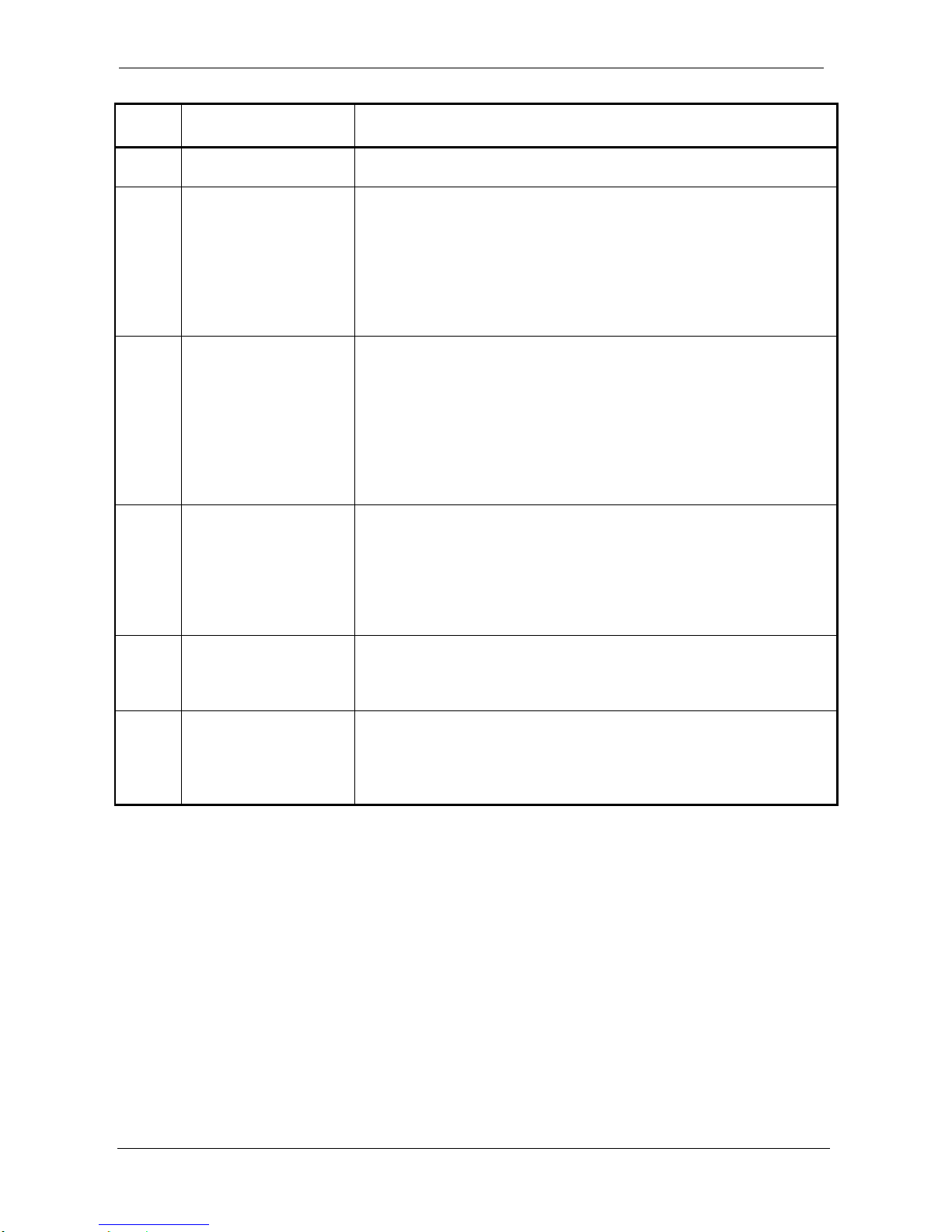
The Data Acquisition is controlled by the state machine on the board. This state machine can be in
one of the following states, which determines the state of the Data Acquisition:
Page 17
ProDAQ 3424 Function Card User Manual 3424-XX-UM
Copyright, 1998-2005 Bustec Production Ltd. Page 17 of 56
STEP
STATE
DESCRIPTION
1
IDLE
(IDLE_ST)
All needed settings (front-end configuration, clock and trigger
selection, Data Acquisition modes) must be done in this step
2
DDS UPDATE
(DDSUD_ST)
Card is brought to this state with the ARMING command if
SYNC_NEED bit has been asserted. In this state, the card
performs the update of the DDS settings. If the board is a Master
then it updates DDS automatically. In the case of a Slave, it waits
for the update pulse generated by the Master and distributed
over SYNC/TRIG line.
This state is skipped if the Arming command is launched with the
SYNC_NEED bit cleared.
3
ADC SYNC
(ADCSYNC_ST)
After DDS UPDATE is done, the card performs reset and thus
synchronization of the ADCs. Similarly to the DDS update, the
Master synchronizes the ADCs automatically while the Slave
waits for the synchronization pulse from the Master. The ADCs
reset and FIR filters settling takes approximately 900ms. At the
end of the process, the Slave gets from the Master another
pulse, which causes them to proceed to next state.
This state is skipped if the Arming command is launched with the
SYNC_NEED bit cleared.
4
READY FOR DA
(READY4DA_ST)
After synchronisation is done, the hardware is ready to start Data
Acquisition. It can either start immediately, or wait for the trigger.
In addition, the card can be configured to acquire the pre-trigger
before the post-trigger phase.
When no pre-trigger and ‘start on trigger’ is selected, the state
machine stays in READY4DA_ST state as long as the trigger is
not asserted.
5
PRE-TRIGGER
(PRET_ST)
If the pre-trigger has been enabled, the card starts to collect pretrigger data. The amount of the scans to collect is defined in the
PRET_NOS register. The number of the pre-trigger samples
must not exceed the FIFO size.
6
POST-TRIGGER
(POSTT_ST)
Post-trigger samples are stored in the FIFO as long as the end of
the Data Acquisition does not happen. The Data Acquisition can
be ended either after a set number of the scans is collected or
after stop trigger event. In this state, it is possible emptying FIFO
on-the-fly for acquisitions longer than the FIFO size.
Table 1 – States of the Data Acquisition state machine
3.3.1. Data Acquisition modes
Data Acquisition is a process of storing samples from ADCs in the FIFO. When the ADCs and
filters have settled (synchronization is done), the board is ready to start Data Acquisition. Data
Acquisition is composed of the pre-trigger and post-trigger. It can be configured to skip the pretrigger.
The pre-trigger, if enabled, starts immediately after synchronization is done. The 3424 card collects
specified number of scans (PRET_NOS register) and stores them in the FIFO. The number of the
pre-trigger samples (number of the scans multiplied by number of the channels enabled for the
Data Acquisition) cannot be bigger than the size of the FIFO, as the readout of the FIFO (emptying
the FIFO) is prohibited in this state. When the required number of the scans is collected, the pretrigger is done but the board stays in the pre-trigger state as long as the conditions to start the
post-trigger are not fulfilled. In this case, every new scan added to the FIFO causes the oldest scan
to be dropped.
Page 18

3424-XX-UM ProDAQ 3424 Function Card User Manual
Page 18 of 56 Copyright, 1998-2005 Bustec Production Ltd.
In some cases, the pre-trigger can be ended before the set number of the scans is collected. This
can happen if the trigger can be accepted before the pre-trigger is finished (PRET_REJECT bit
cleared) and start trigger event took place. If the user wants to collect the entire specified pretrigger, the PRET_REJECT bit has to be set. In this case, triggers coming before completion of the
pre-trigger are rejected.
If the pre-trigger is ended before completion, then the PRET_NOS register readout returns the
number of scans left to complete.
The post-trigger starts when the start condition is met. The start condition is selected with the
DA_STARTSEL bit. The following ways can be selected:
Post-trigger starts immediately after the ADCs and filters are settled (if pre-trigger has been
disabled) or after pre-trigger is done (if the pre-trigger has been enabled)
After the trigger event happens
The post-trigger ends when the Data Acquisition stop condition is met. The stop conditions of the
Data Acquisition are as follows:
Selected number of scans has been collected (DA_STOPSEL bits set to ‘00’)
Stop trigger happens (DA_STOPSEL bits set to ‘01’)
Software stop (DA_SKIP or SW_RST bits set)
Error happens (if STOP_ON_ERR bit set and any error enabled)
Up to 16,777,215 post-trigger scans can be set in the POSTT_NOSL/H registers. The unlimited
number of samples can be achieved by setting stop mode to DA_SKIP (DA_STOPSEL bits set to
‘10’).
3.3.2. Data storage and readout
The samples are stored in the on-board FIFO memory. The depth of the FIFO is 64 ksamples
(optionally it can be 128 ksamples). The samples are stored scan-by-scan, with the channel data
interleaved within the scan (channel with the lower number goes first). The scan is composed of
one to eight channels
The write to the FIFO is always 32-bit wide. The write can be performed by the motherboard during
idle state (FIFO_WRL/H registers) or by the ADCs during Data Acquisition. The 24-bit data from
the ADC is extended to the 32-bit, two’s complement format.
The readout from the FIFO can be either 16-bit or 32-bit wide, which is selected using FIFO_16B
bit. The readout initiated by the motherboard is disabled in the pre-trigger mode.
The two read out modes from the FIFO memory are:
16-bit readout: motherboard in the first access reads the 16 least significant bits from the
FIFO, the following access is used to read 16 most significant bits. This mode is supported
on both, 3120 and 3150 motherboards
32-bit readout: two stacks (A and B) are used to read all 32 bits in one access. This mode is
supported only on 3150 motherboard and improves the throughput significantly when
emptying FIFO on-the-fly.
The FIFO memory chip outputs five status flags:
1) empty flag
2) almost empty flag
3) half flag
4) almost full flag
5) full flag
Page 19
ProDAQ 3424 Function Card User Manual 3424-XX-UM
Copyright, 1998-2005 Bustec Production Ltd. Page 19 of 56
The flags are used to control the number of the samples stored in the FIFO when emptying this
memory. The status of the FIFO flags can be read directly (FIFO_CTRL register) or selected flag
(only one) can be directed to the Output Trigger or Direct Interrupt.
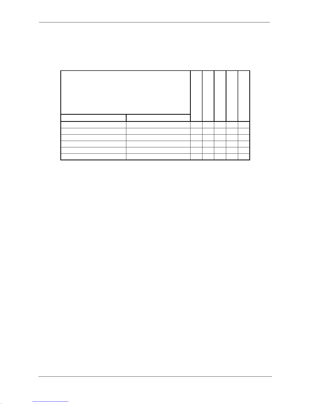
The following table defines the FIFO flag assertion:
Number of samples in FIFO
Empty
Almost Empty
Half
Almost Full
Full
64 ksamples FIFO
128 ksamples FIFO
0
0
1 1 0 0 0
1 to (n+1)
1 to (n+1)
0 1 0 0 0
(n+2) to 32769
(n+2) to 65537
0 0 0 0 0
32770 to (65536-m)
65538 to (131072-m)
0 0 1 0 0
(65537-m) to 65536
(131073-m) to 131072
0 0 1 1 0
65537
131073
0 0 1 1 1
Table 2 – FIFO flag thresholds
The offsets: n and m are programmable. Their default value (after FIFO master reset) is 255. They
can be updated using FIFO_WRL/H registers (bits used: 16 LSB bits for 64 ksamples FIFO and 17
LSB bits for 128 ksamples FIFO) if the FIFO_LD bit has been set. The first access stores n offset,
the second access stores m offset, then the sequence repeats.
The FIFO master reset (FIFO_MRS bit) has to be performed during the board initialisation.
Afterwards, the partial reset is sufficient to reset the FIFO as it resets the pointers only.
3.3.3. FIR filters and decimation
To achieve even lower output sampling rates with the same fixed analog filter, two decimation
stages by 10 are implemented in FPGA. Internal multiplexer in the FPGA allows for selection which
data is to be stored in the FIFO. Either not decimated samples, samples decimated by 10 (one
decimation stage), or samples decimated by 100 (two decimation stages) can be selected.
However, such selection applies to all channels, i.e. all channels must work with the same output
sampling rate. With such approach, output sample rate of the card spreads from as low as 200Hz
to 216kHz.
Theoretical passband frequency of FIR filter spreads from 0.08 rad / sample (0.04 of the FIR
input sample rate). The frequency response is extremely flat in this area and has ripple of only
2.5dB. Stopband starts at 0.1 rad / sample (0.05 of the FIR input sample rate) with attenuation
of 126dB. Very narrow transition band and high requirements to the ripple and attenuation values
resulted in filter order of 802. Symmetrical coefficients ensure linear phase response in the
passband.
To minimize effects of fixed point arithmetic implementation (quantization error), 28-bit coefficient
length is used.
3.3.4. Sampling settings
Page 20
3424-XX-UM ProDAQ 3424 Function Card User Manual
Page 20 of 56 Copyright, 1998-2005 Bustec Production Ltd.
To start Data Acquisition, ADC sampling clock selection and ADC output speed rate has to be setup.
The sampling clock can be generated on the board out of the reference clock (2 MHz) or it can be
received from the external generator (for example from the other Master) as a target ADC sampling
clock.
When generating ADC clock on the board, a 2 MHz reference clock can be taken from one of
these sources:
Local 2 MHz oscillator
Reference clock received through the stack B trigger input line and a switch matrix on the
motherboard from another ProDAQ function card
Reference clock received through the front panel from another function card or other
external clock source
This reference clock is used then to produce 125 MHz DDS input clock. DDS circuitry is used to
synthesise the clock in the range from 12.5 MHz to 25 MHz. Together with two additional frequency
dividers (the reason for them is jitter performance optimisation outside main DDS octave) it allows
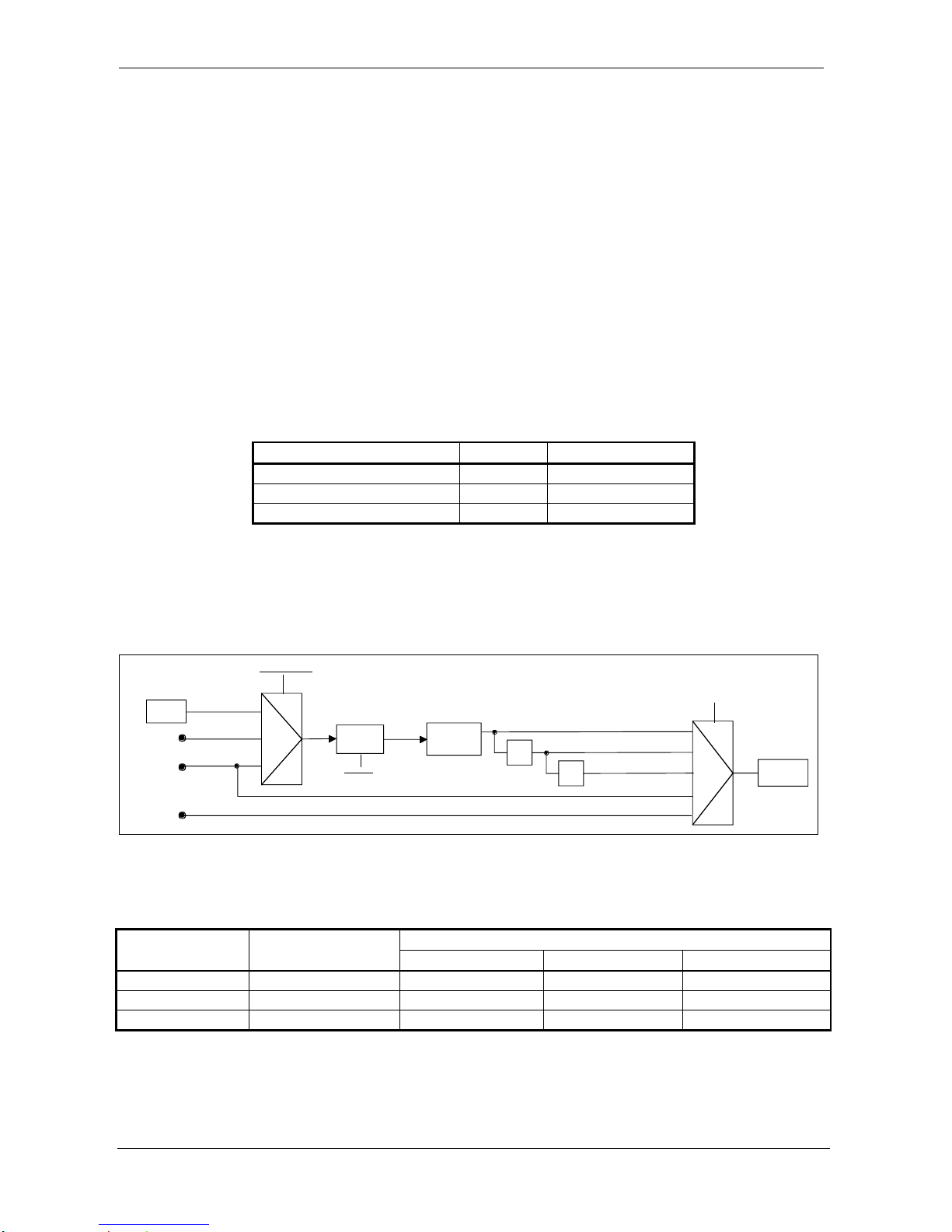
for generation of any ADC clock in the range of 5.12 MHz to 13.824 MHz. The Table 3 shows the
DDS configuration and the corresponding ADC clock frequencies.
DDS output clock [MHz]
CLKSEL
ADC clock [MHz]
20.48 – 25
111
5.12 – 6.25
12.5 – 25
110
6.25 – 12.5
12.5 – 13.824
101
12.5 – 13.824
Table 3 – DDS settings for the required ADC clock frequency
The details on the DDS frequency programming can be found in DDS_WX register description.
In addition to the on-board generator, the target ADC clock can be taken from front panel clock
input as well as from local synchronization link clock line. Figure 5 shows the ADC clock
configuration scheme.
nTRIGI_B
OSC
PLL
DDS
125MHz
2MHz
FPCLK_IN
/2
/2
LCLK
12.5 - 13.824 MHz.
6.25 - 12.5 MHz.
5.12 - 6.25 MHz.
CLKSEL[2:0]
PLL_RSEL[1:0]
ADC clock
(MCLK)
0xx
100
101
110
111
01
10
11
PLL_EN
Figure 5 – ADC clock configuration
The possible output word rates for the given ADC clock and speed settings are shown in Table 4.
ADC clock
[MHz]
ADC SPEED
(over-sampling)
Output word rate [kHz]
Decimation=Off
Decimation=10
Decimation=100
5.12 – 13.824
Normal (x128)
20 – 54
2.0 – 5.4
0.2 – 0.54
5.12 – 13.824
Double (x64)
40 – 108
4.0 – 10.8
0.4 – 1.08
5.12 – 13.824
Quad (x32)
80 – 216
8.0 – 21.6
0.8 – 2.16
Table 4 – ADC output word rates
For the overlapping regions of the output word rate use the option with the higher over-sampling for
better performance.
Page 21
ProDAQ 3424 Function Card User Manual 3424-XX-UM
Copyright, 1998-2005 Bustec Production Ltd. Page 21 of 56
3.3.5. Input Trigger
Input Trigger can be used to start or to stop collecting post-trigger data, depending on the Data
Acquisition start/stop mode. The following Input Trigger sources are available:
Trigger from the switch matrix on the motherboard, stack A
Trigger from the switch matrix on the motherboard, stack B
Trigger from the front panel
Trigger from the local synchronization link
Analog trigger
Software trigger
Any number of the sources listed above can be selected at the same time.
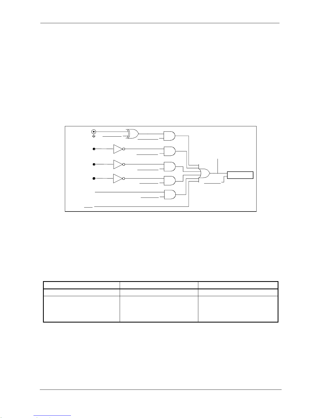
The Input Trigger configuration scheme is shown on Figure 6.
FPSYNC_LOW
FPSYNC_IO
FPSYNC2IT_EN
MBTRGA2IT_EN
SW2IT
nTRIGI_A
ITRIG_STS
LSYNC2IT_EN
nLSYNC
ATRIG2IT_EN
ANALOG TRIGGER
MBTRGB2IT_EN
nTRIGI_B
ITRIG_LEVEL
INPUT
TRIGGER
Figure 6 – Input Trigger configuration scheme
Input Trigger is used only if the 3424 is configured as a Master, otherwise Input Trigger stays in
reset and the function card is controlled by the synchronization pulses coming from a remote
Master.
Input Trigger logic detects two events on the trigger source lines that can be used to start or to stop
the Data Acquisition depending on the DA_START_SEL and DA_STOP_SEL bits settings. Input
Trigger reacts on edge or on level. The edge requires the transition while the level requires the
state. Selection of the edge/level mode is common for the start and the stop events.
Table 5 shows the definition of the start and stop events.
MODE
START EVENT
STOP EVENT
Level (ITRIG_LEVEL=’1’)
Active state
Inactive state
Edge (ITRIG_LEVEL=’0’)
Inactive-to-Active transition
Active-to-Inactive transition
when STOPTRIG_ESEL=’0’,
Inactive-to-Active transition
when STOPTRIG_ESEL=’1’
Table 5 – Input Trigger start and stop events
Active state of the triggers coming from the VXI backplane / switch matrix and from the local
synchronization link is always low. Active state of the front panel source is software selectable
(FPSYNC_LOW bit).
Input Trigger can be accepted when the Data Acquisition is ready to be started. During IDLE, DDS
UPDATE and ADC SYNC states Input Trigger logic rejects coming trigger events.
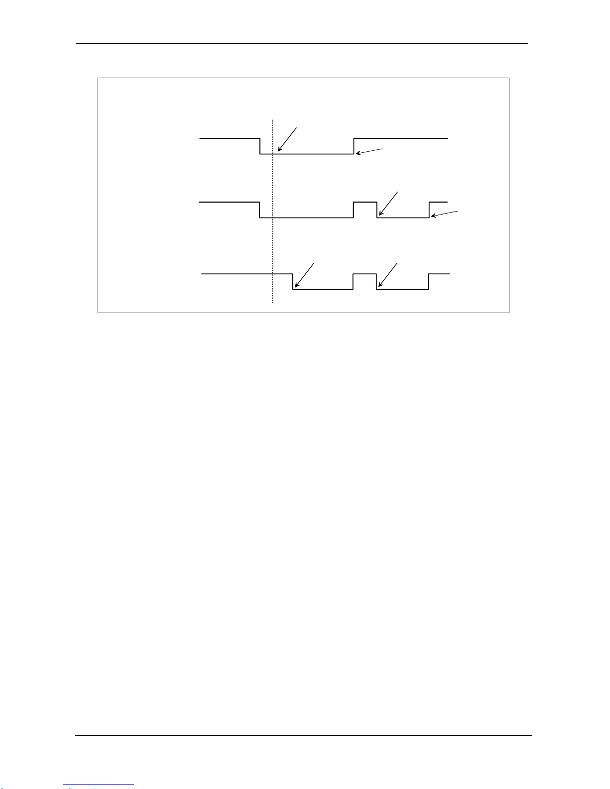
Examples of the Input Trigger configuration are shown on Figure 7.
Page 22
3424-XX-UM ProDAQ 3424 Function Card User Manual
Page 22 of 56 Copyright, 1998-2005 Bustec Production Ltd.
Start and Stop events enabled
Pre-trigger disabled
Level mode
Trigger from VXI
DA starts here
Post-trigger
starts here
Post-trigger
stops here
Edge mode
Stop event:
Active-to-Inactive
Trigger from VXI
Post-trigger
starts here
Post-trigger
stops here
Edge mode
Stop event:
Inactive-to-Active
Trigger from VXI
Post-trigger
starts here
Post-trigger
stops here
Figure 7 – Examples of the Input Trigger configuration
3.3.6. Output Trigger, Direct Interrupt and Direct Error
Output Trigger, Direct Interrupt and Direct Error provide the way of sending out the information
about some events, which occur on the 3424. Because of the fact that the 3424 is double width
function card, two trigger outputs are available as well as two Direct Interrupts and one Direct Error.
The sources of the trigger and interrupts are listed below:
1) Trigger output, stack A:
FIFO flag
Error flag
Analog trigger
Data Acquisition On (DA_ON) flag
Data Acquisition End (DA_END) flag
Software generated trigger
2) Trigger output, stack B (only one source can be enabled for this trigger):
Reference clock
Analog trigger
3) Direct Interrupt, stack A:
FIFO flag
4) Direct Interrupt, stack B:
Data Acquisition End (DA_END) flag
5) Direct Error, stack A:
Error flag
Note that after arming command, no new FIFO flag triggers/interrupts are generated until card
reaches post-trigger state. This is to allow for collecting more pre-trigger scans than the selected
FIFO threshold without generating an interrupt, so that the FIFO flag trigger/interrupt will be
generated only when there is data in the FIFO that can be read (reading from FIFO is forbidden
when the card is in pre-trigger state).
Stack A is always an odd stack number of the stacks occupied by the function card while stack B is
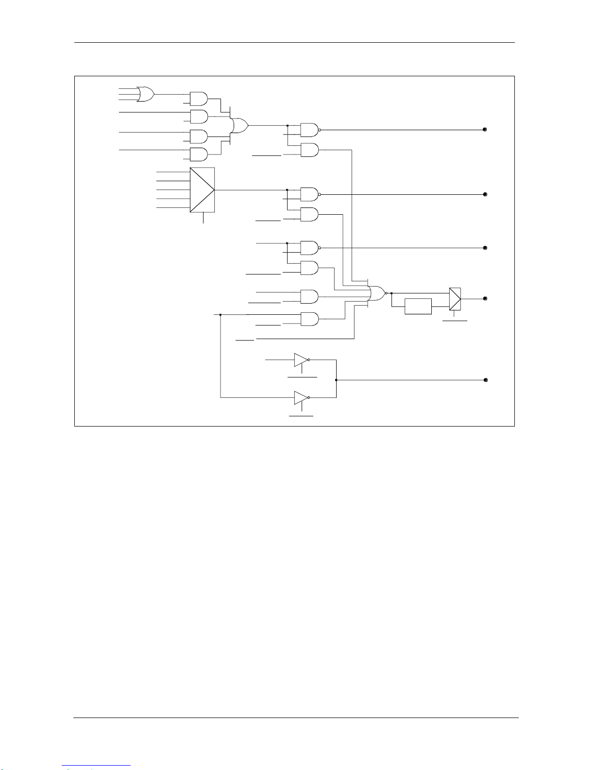
an even stack number. Figure 8 shows the configuration scheme of all output signals.
Page 23
ProDAQ 3424 Function Card User Manual 3424-XX-UM
Copyright, 1998-2005 Bustec Production Ltd. Page 23 of 56
nTRIGO_B
RCLK2OTB_EN
T
RI-STATE
AT2OTB_EN
T
RI-STATE
Reference Clock
ERR4_EN
ERR1_EN
ERR2_EN
ERR3_EN
DDSUD_ERR
SCAN_ERR
MCLKRANGE_ERR
OUTRANGE_ERR
AOVFL_ERR
FOVLD_ERR
Empty Flag
Full Flag
Almost Empty Flag
Almost Full Flag
Half Flag
FIFOFLAG_SEL
DAEND
DAON
Analog Trigger
SW2OTA
ERR2OTA_EN
ERR2DE_EN
FF2OTA_EN
FF2DIA_EN
DAEND2OTA_EN
DAEND2DIB_EN
AT2OTA_EN
DAON2OTA_EN
Pulse
Generator
OTA_LEVEL
nTRIGO_A
nDI_B
nDI_A
nDE
Figure 8 – Output Trigger, Direct Interrupt and Direct Error configuration scheme
The Output Trigger can be generated as a pulse or as level. If the level has been selected the
Output Trigger stays active as long as the source of the trigger is active. If the active time is shorter
than 200ns then the function card keeps the trigger asserted for this time. For the pulse settings,
the pulse of 200ns is generated every time the source of the trigger becomes active.
Direct Interrupt is used to send the interrupt to the LIST processor on the ProDAQ 3150
motherboard without using the trigger output line. The LIST processor reaction to the Direct
Interrupt is much faster than the reaction to the trigger line so this feature is very useful when for
example emptying FIFO on-the-fly is needed. Direct Interrupt line can be used only when 3424
function card is used together with 3150 motherboard.
Direct Error can be used only when 3424 function card works together with 3150 motherboard.
Lower and upper stack share the same Direct Error line so after error was set the software has to
detect which board generated Direct Error by polling FCCSR register.
There are following error sources on the 3424 board:
DDS update error (DDSUD_ERR) – happens if the board is a Slave and the external
SYNC/TRIG pulse is not in phase
Scan error (SCAN_ERR) – happens if the samples from the ADC comes too often. This
might be caused by the higher than allowed ADC clock frequency
ADC clock out-of-range error (MCLKRANGE_ERR) – happens if the ADC clock frequency is
outside of the required range (5.12 MHz to 13.824 MHz)
Page 24
3424-XX-UM ProDAQ 3424 Function Card User Manual
Page 24 of 56 Copyright, 1998-2005 Bustec Production Ltd.
Input signal out-of-range error (OUTRANGE_ERR) – happens if the input signal is out of
range for selected gain (10V for gain=1, 5V for gain=2, etc.)
Arithmetic overflow error (AOVFL_ERR) – happens if the arithmetic overflow in the gain
correction or FIR filter occurs. Note that the output sample in this case gets saturated to Full
Scale (positive or negative, depending in which direction arithmetic overflow happened)
FIFO overload error (FOVLD_ERR) – happens if the FIFO is full and next samples is ready
to be written
3.3.7. Analog Trigger
Analog Trigger is useful in acquiring transient signals by nature, e.g. vibrations after striking beam
with a hammer.
If enabled, Analog Trigger is generated when the input signal in the chosen analog channel meets
specified conditions. Analog Trigger can be used as a source of the on-board Input Trigger or it
can be selected as a source of the Output Trigger and forwarded further to remote Master.
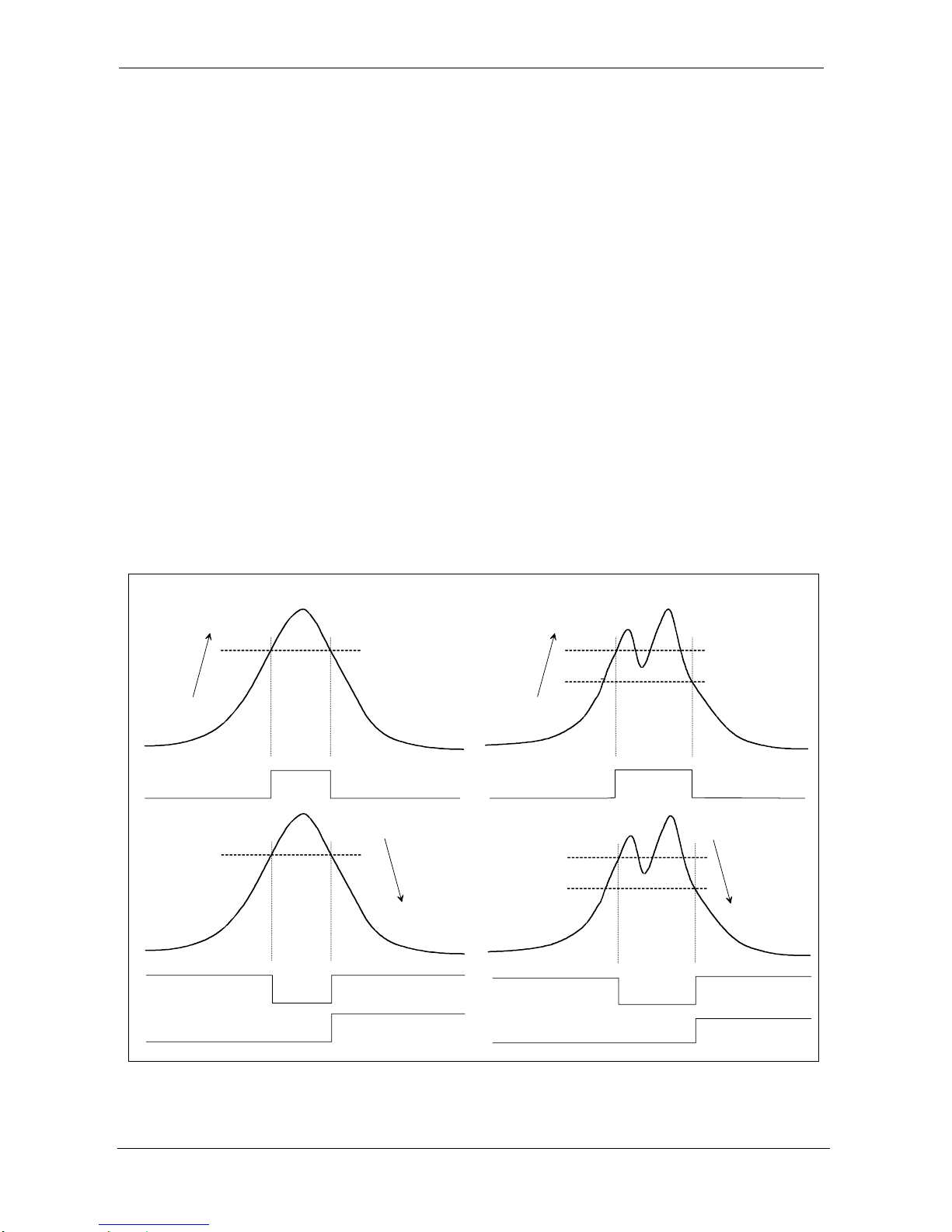
There are two Analog Trigger modes: edge and level (see Figure 9). Both can be specified as
“positive slope/greater-or-equal” or “negative slope/less-or-equal” directions. In the edge mode the
signal must cross the specified threshold while for the level it is not required and thus the difference
between the edge and level might happen only when the Data Acquisition starts.
The Analog Trigger can be programmed with or without hysteresis. When the hysteresis is not
required, only one threshold has to be defined, THR1. For the hysteresis mode, two thresholds
have to be defined, THR1 and THR2. In hysteresis mode, THR1 has to be crossed first
independently on the selected direction.
Threshold
THR1
Positive slope /
Geater-equal
Analog Trigger
(edge or level)
Threshold
THR1
Analog Trigger
(level)
Analog Trigger
(edge)
Negative slope /
Less-equal
Threshold
THR2
Positive slope /
Geater-equal
Analog Trigger
(edge or level)
Threshold
THR1
Analog Trigger
(level)
Analog Trigger
(edge)
Negative slope /
Less-equal
Threshold
THR1
Threshold
THR2
WITHOUT HYSTERESIS WITH HYSTERESIS
Figure 9 – Analog Trigger modes explanation
Page 25

ProDAQ 3424 Function Card User Manual 3424-XX-UM
Copyright, 1998-2005 Bustec Production Ltd. Page 25 of 56
Any channel signal can be selected as a source of the Analog Trigger, however only one channel
can be selected at a time. The Analog Trigger is implemented in the digital domain and the
thresholds are programmable with 12-bit resolution.
3.3.8. Analog channel correction
The board provides the correction of the analog channel offset and gain.
The offset correction is done with the DAC. To calibrate an offset, the channel input (both positive
and negative paths) must be grounded. To achieve that, the software should set VREFGND_EN bit
for selected channel to ‘1’ and reset VREF_ON bit in MODE2 register to ‘0’. A value for the offset
DAC should be set to 0x8000 and an ADC value shall be read (OFFMIN). Then a value for offset
DAC should be set to 0x8FFF and an ADC value shall be read again (OFFMAX). It is a good
practice to acquire a big number of samples (for example 10 000) and then average them to
calculate both OFFMIN and OFFMAX. This causes that the calibration process is not affected by
noise. The final value of the offset correction coefficient (OFFCOEF) that should be written to offset
DAC is calculated as follows:
][1
][
80000)_16(
4095
][][
][1
VLSBOFF
VOFFMIN
xvaluebitOFFCOEF
VOFFMINVOFFMAX
VLSBOFF
Gain correction is performed in digital domain inside FPGA. To calibrate the gain, the known
precise voltage needs to be supplied to the channel input. The ProDAQ 3201 voltage reference
module can be used for this purpose. The software should set VREFGND_EN bit for selected
channel to ‘1’ and set VREF_ON bit in MODE2 register to ‘1’. The ProDAQ 3201 should be
programmed to the required voltage. Note that only one channel should be connected to the VREF
at a time. ADC value is then obtained (GAINERR). Also in this case it is advised to acquire a big
number of samples (for example 10 000) and then average them to calculate GAINERR value. The
final 24-bit value of the gain correction coefficient (GCOEF) that should be written to GCOEFL and
GCOEFH registers is calculated as follows:
24
2
][24.102
][1
V
VLSB
8000000
][1
][
)_24( x
GAINERR
VLSB
VVREF
valuebitGCOEF
Offset and gain correction coefficient values can be stored in the EEPROM memory. The on-board
EEPROM memory is big enough to accommodate separate offset and gain calibration data for
every channel and for every gain. Default offset and gain correction coefficients (for gain=1) are
automatically uploaded on the power-up. Calibration coefficients for different gains should be read
from EEPROM memory and then written to respective registers by software.
The card is shipped factory calibrated, i.e. with correction coefficients stored in the EEPROM
memory for all possible gain selections. For the purpose of calibration in the field by the user, the
ProDAQ 3201 voltage reference board is needed.
3.3.9. Multiple cards configuration
Page 26
3424-XX-UM ProDAQ 3424 Function Card User Manual
Page 26 of 56 Copyright, 1998-2005 Bustec Production Ltd.
The 3424 is able to work in the stand-alone mode or in multiple-card synchronization mode.
The multiple-card synchronization mode is used in the case when all 3424 boards have to sample
the input signal simultaneously and when Data Acquisition has to start in the same time on all of
them.
The 3424 can be set as a Master (MASTER bit in FCCSR register set) or Slave (MASTER bit
cleared). If 3424 works in a stand-alone mode then it has to be always a Master. If the group of the
3424 boards work in a multiple-card synchronization mode then only one function card can be set
as a Master and all others as a Slaves.
The Master generates two signals that have to be distributed to all Slaves: clock signal and
SYNC/TRIG signal.
The clock signal can be distributed as a PLL reference clock (2 MHz low frequency signal
multiplied then in the PLL to 125 MHz for DDS circuitry) or as a sampling clock applied directly to
the ADCs (5.12 MHz to 13.824 MHz). Depending on the selected clock signal, proper settings on
the Slaves have to be done.
The Master is able to send the clock signal to the following outputs:
1) PLL reference clock
Trigger output, stack B
Front panel clock output
2) ADC clock
Local synchronization link clock line
Front panel clock output
The configuration of the Master where the reference clock is send to the trigger output and the
ADC clock is send to the local synchronization and/or front panel clock outputs is allowed.
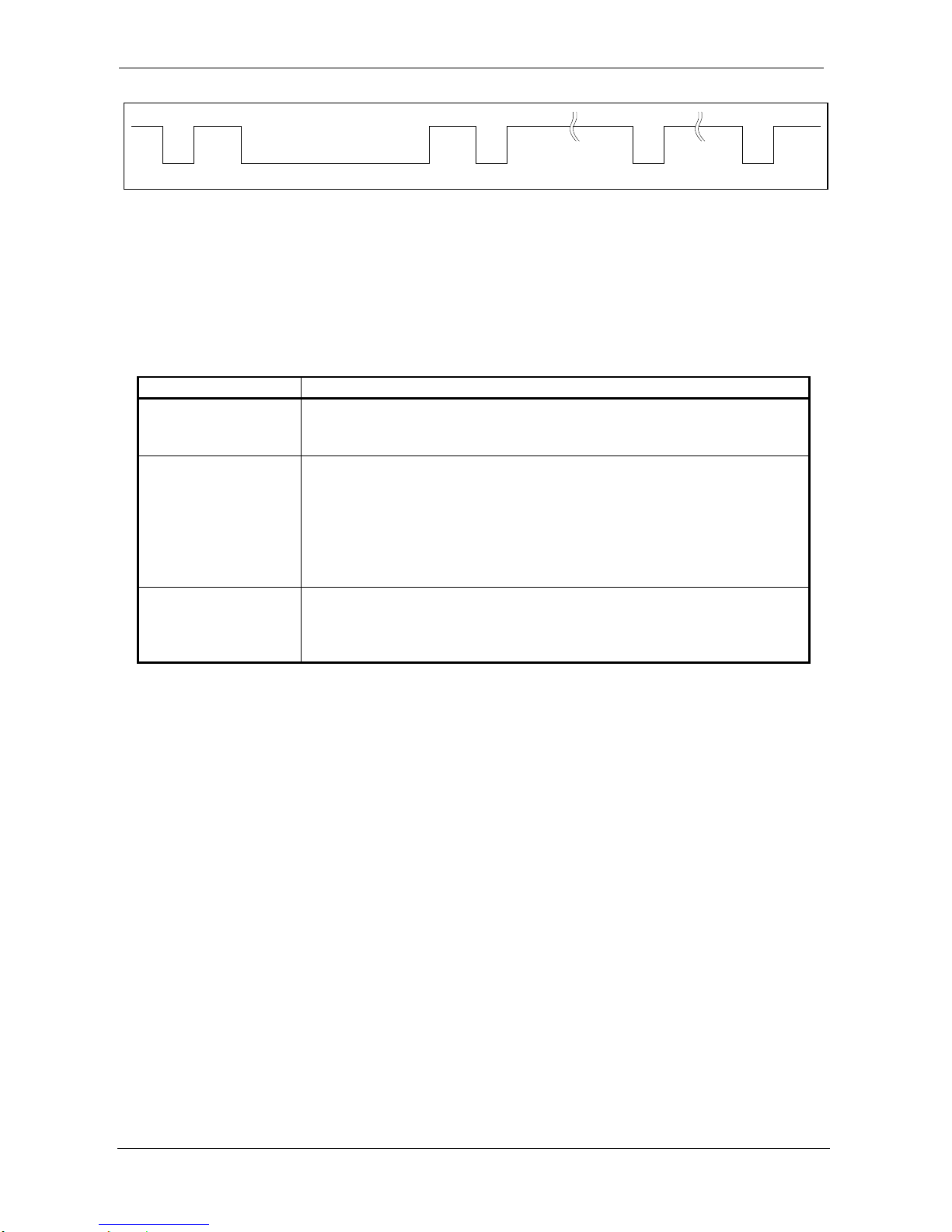
The second signal generated by the Master is SYNC/TRIG signal. It is used to synchronize all
ADCs and start Data Acquisition at the same time. The SYNC/TRIG events are described in Table
6.
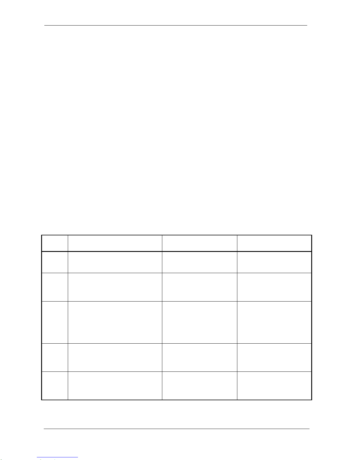
PHASE
EVENT
CONDITION
PULSE
P1
update of the DDS – this pulse
is used by the boards which
receive PLL reference clock
Occurs only if the board
armed together with the
SYNC_NEED bit set
P1, width of 200ns
P2
reset and settling of the ADCs
– this pulse resets ADCs and
ensures the settling time of the
FIR filters
Occurs only if the board
armed together with the
SYNC_NEED bit set
P2, width of approx.
896ms, synchronized to
the falling edge of the
ADC clock
P3
start of the Data Acquisition –
this pulse tells the Slave to start
Data Acquisition (go to pre/post
trigger or wait for the start/stop
trigger events, depending on the
settings)
Always present
P3, width of 5 ADC
clocks, synchronized to
the falling edge of the
ADC clock
P4
start trigger event – this pulse
tells the Slaves to go to the post
trigger
Occurs if the start on
trigger selected on the
Master and start trigger
event happens
P4, width of 2 ADC
clocks, synchronized to
the falling edge of the
ADC clock
P5
stop trigger event – this pulse
tells the Slaves to finish post
trigger
Occurs if the stop on
trigger selected on the
Master and stop trigger
event happens
P5, width of 2 ADC
clocks, synchronized to
the falling edge of the
ADC clock
Table 6 – SYNC/TRIG signal events
Page 27
ProDAQ 3424 Function Card User Manual 3424-XX-UM
Copyright, 1998-2005 Bustec Production Ltd. Page 27 of 56
P1
P2 P3 P4 P5
DDS update
ADC reset/settling DA start
start trig event stop trig event
Figure 10 – The series of the pulses on SYNC/TRIG signal
The Master is able to send the SYNC/TRIG signal (active low) to any of these outputs:
- Trigger output, stack A
- Local synchronization link
- Front panel FPSYNC_IO line
The clock and SYNC/TRIG signals have to be delivered from the Master to the Slaves. There are
three possible distribution ways shown in the Table 7.
Distribution way
Description
Local
synchronization link
Local synchronization link connects boards sitting on the same
motherboard (up to 3 Slaves connected to the Master). It uses
special connectors and cables going across the function cards.
VXI bus
VXI distribution connects 3424 boards residing on the motherboards
on the VXI bus to the Master. This distribution way is implemented
with the VXI triggers. The SYNC/TRIG and clock signals go to the
trigger outputs on the Master (stack A and B respectively) and then
through the VXI trigger lines they are distributed to all Slaves (trigger
inputs, stack A and B on the Slaves). The clock signal can be
distributed over VXI bus only as a reference clock (not ADC clock)
Front panel
Front panel distribution can be used to connect the Master to the
Slaves sitting on the motherboards in the same VXI chassis or in the
other chassis. The SYNC/TRIG signal can be distributed over front
panel as well a reference clock or ADC clock
Table 7 – Ways of clock and SYNC/TRIG signal distribution
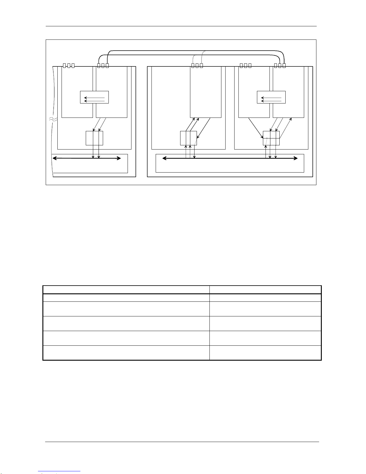
The simplified link scheme of the multiple 3424 boards synchronization is shown on Figure 11.
The synchronisation of the multiple boards requires that settings of the Slaves have to correspond
to the settings of the Master. In addition, the arming of the Slave has to occur before the arming of
the Master. After the end of the Data Acquisition on the Master, the software has to check if all
Slaves finished their Data Acquisition processes.
The Analog Trigger on the Slaves can be used to trigger the Master in the same way as Analog
Trigger on the Master. The Analog Trigger from the Slaves has to be linked to the Input Trigger of
the Master via VXI trigger lines.
Page 28
3424-XX-UM ProDAQ 3424 Function Card User Manual
Page 28 of 56 Copyright, 1998-2005 Bustec Production Ltd.
LOCAL LINK
M
ASTER
S
LAVE
S
LAVE
S
LAVE
VXI BUS TRIGGERS
VXI CHASSIS 2
SYNC/TRIG
REF/ADC CLK
SMSMSM
nTRIGO_B
nTRIGO_A
nTRIGI_A/B
nTRIGO_A/B
nTRIGO_A/B
nTRIGI_A
nTRIGI_B
ALTERNATE
L
INK
REF
CLK
SYNC/TRIG
ATRIG
ATRIG
SYNC/TRIG
ATRIG
FPSYNC_IO
FPCLK_OUT
FPCLK_IN
FPCLK_OUT
FPCLK_IN
FPCLK_OUT
FPCLK_IN
FPCLK_OUT
FPCLK_IN
MB MBMB
ADC CLK
SYNC/TRIG
REF
CLK
FPSYNC_IO
FPSYNC_IO
FPSYNC_IO
LOCAL LINK
VXI BUS TRIGGERS
SM
nTRIGO_B
nTRIGO_A
REF
CLK
SYNC/TRIG
FPCLK_OUT
FPCLK_IN
SYNC/TRIG
FPSYNC_IO
ADC CLK
VXI CHASSIS 1
S
LAVE
Figure 11 – Multiple boards link scheme
A 3424 card being a Slave can also forward clock and SYNC/TRIG signals to other Slaves. It is
useful in multi-chassis VXI systems. The Slave located in the chassis without active Master
forwards SYNC/TRIG and clock coming through the front panel to the other Slaves using VXI bus
triggers or local synchronization link. Note that only PLL reference clock can be forwarded to the
VXI bus triggers. The Slave card in the chassis without active Master can’t generate Analog
Trigger, since there is simply no way to route it to the Master’s chassis.
When synchronizing multiple cards, an inevitable cross channel phase error appears. This
happens because of propagation delay of SYNC/TRIG and clock signals. Typical clock phase shift
between Master and Slave clock for different link schemes is given in Table 8.
Synchronization link scheme
Typical sampling clock phase shift
Local synchronization link
8 ns
Synchronization through the trigger lines, cards on the
same motherboard
19 ns
Synchronization through the trigger lines, cards on
different motherboards
36 ns
Synchronization through the front panel, distribution of
ADC clock (20 cm long cable)
13 ns
Synchronization through the front panel, distribution of
reference clock (20 cm long cable)
18 ns
Table 8 – Typical clock phase shift between Master and Slave cards.
This phase shift is insignificant for most low-frequency applications, since the signal phase error is
proportional to the signal frequency. For example, 36 ns of the Master and Slave clock phase shift
corresponds to 0.0026 degree of the cross channel phase mismatch for 200 Hz signal and 0.26
degree for 20 kHz signal.
It is worth to remember that the cable adds approximately 6 ns delay per meter. This needs to be taken into
account when external cables are used to connect Master and Slave cards, i.e. when front panel connectors are
used to send SYCN/TRIG and clock signals. The values in the Table 8 are valid for 20 cm long cable.
Page 29
ProDAQ 3424 Function Card User Manual 3424-XX-UM
Copyright, 1998-2005 Bustec Production Ltd. Page 29 of 56
4. Front Panel Connectors
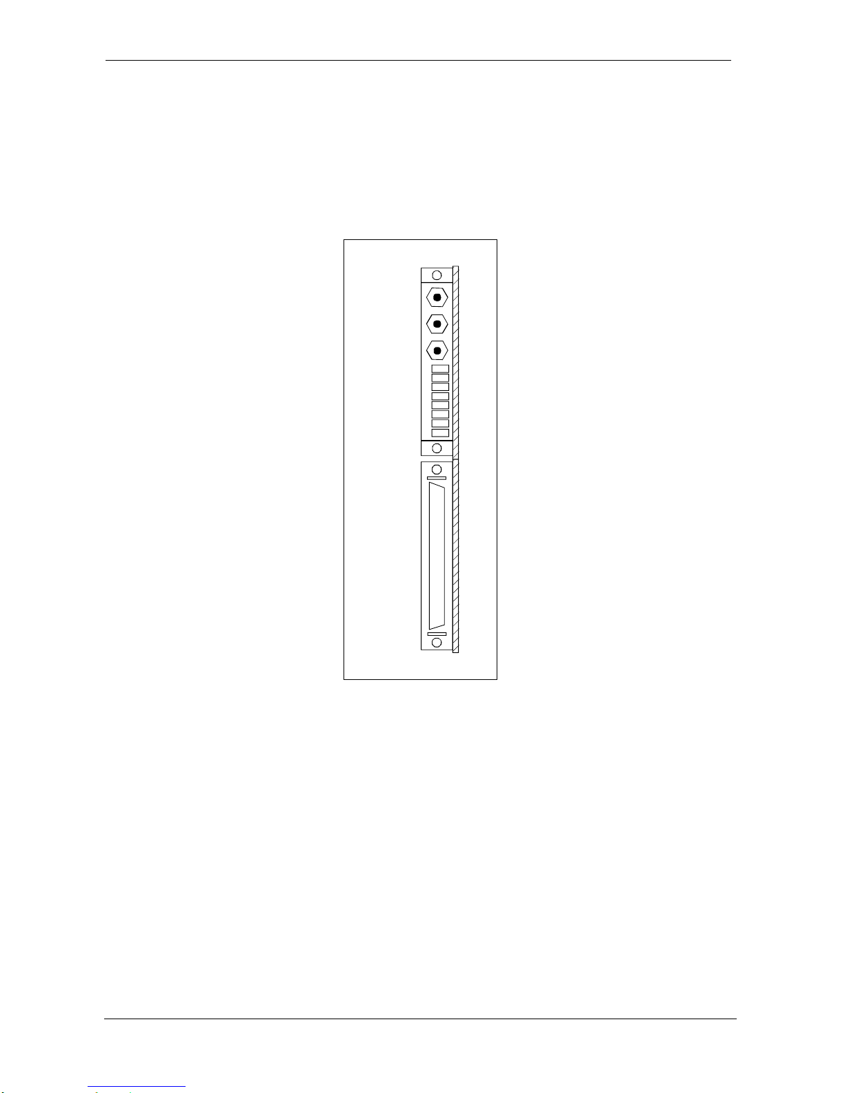
The front panel of the 3434 card contains:
high density, 50 pin, female SCSI type connector used for analog signal connections
8 LED diodes to indicate ICP excitation current in respective channel
3 SMB connectors for digital signals used for synchronization purposes
The view of the front panel layout is shown on the Figure 12.
1 26
5025
FPCLK_IN
FPCLK_OUT
LED 8
LED 1
FPSYNC_IO
Figure 12 – Front panel connectors layout
(view when 3424 card is fitted on ProDAQ module in VXI chassis)
The signal assignment on the front panel SCSI connector is shown in Table 9. Note that the power
supplies (+24V, +15V, +5V, -15V) available on the front panel have limited current load and are
available exclusively for supplying signal conditioning boards manufactured or accepted by Bustec.
Page 30
3424-XX-UM ProDAQ 3424 Function Card User Manual
Page 30 of 56 Copyright, 1998-2005 Bustec Production Ltd.
Signal
Pin
Pin
Signal
+24V
1
26
Ground
Cable Shield
2
27
SENSE ICP 8
CHN8-
3
28
CHN8+
+15V
4
29
Ground
Cable Shield
5
30
SENSE ICP 7
CHN7-
6
31
CHN7+
+5V
7
32
Ground
Cable Shield
8
33
SENSE ICP 6
CHN6-
9
34
CHN6+
-15V
10
35
Ground
Cable Shield
11
36
SENSE ICP 5
CHN5-
12
37
CHN5+
Cable Shield
13
38
Ground
Cable Shield
14
39
SENSE ICP 4
CHN4-
15
40
CHN4+
Cable Shield
16
41
Ground
Cable Shield
17
42
SENSE ICP 3
CHN3-
18
43
CHN3+
Cable Shield
19
44
Ground
Cable Shield
20
45
SENSE ICP 2
CHN2-
21
46
CHN2+
Cable Shield
22
47
Ground
Cable Shield
23
48
SENSE ICP 1
CHN1-
24
49
CHN1+
Cable Shield
25
50
Ground
Table 9 – Signal assignments on the front panel SCSI connector
Page 31
ProDAQ 3424 Function Card User Manual 3424-XX-UM
Copyright, 1998-2005 Bustec Production Ltd. Page 31 of 56
5. Register Description
All addresses are given in hexadecimal notation. FC_ADR is address in the function cards address
space. VXI_ADR is address in VXI address space (refer to the motherboard manual for more
details).
Register Name
FC_
ADR
VXI_
ADR
Acces
s Type
Function
FCID
0 0 RO
Function card ID register
FCVER
1 4 RO
Function card version register
FCCSR
2 8 R/W
Function card control and status register
MODE1
3 C R/W
Mode1 register
MODE2
4
10
R/W
Mode2 register
OTRI_CFG
5
14
R/W
Output Trigger configuration register
ITRI_CFG
6
18
R/W
Input Trigger configuration register
FIFO_CTRL
7
1C
R/W
FIFO control register
FIFO_WRL
8
20
R/W
FIFO write low register
FIFO_WRH
9
24
WO
FIFO write high register
PRET_NOS
A
28
R/W
Number of pre-trigger samples
POSTT_NOSL
B
2C
WO
Number of post-trigger samples, low
POSTT_NOSH
C
30
WO
Number of post-trigger samples, high
AT_THR_SIGERR
D
34
R/W
Analog Trigger threshold / signal error register
AT_CTRL
E
38
WO
Analog Trigger control register
CHN1CFG
F
3C
R/W
Channel #1 configuration register
CHN2CFG
10
40
R/W
Channel #2 configuration register
CHN3CFG
11
44
R/W
Channel #3 configuration register
CHN4CFG
12
48
R/W
Channel #4 configuration register
CHN5CFG
13
4C
R/W
Channel #5 configuration register
CHN6CFG
14
50
R/W
Channel #6 configuration register
CHN7CFG
15
54
R/W
Channel #7 configuration register
CHN8CFG
16
58
R/W
Channel #8 configuration register
DDS_WX
17
5C
R/W
DDS control words register
DAC_DATA
18
60
WO
DAC data register
DAC_ADDR
19
64
R/W
DAC address register
TEDS_ACC
1A
68
R/W
TEDS access register
GCOEFL
1B
6C
WO
Gain coefficient write, bits 15..0
GCOEFH
1C
70
WO
Gain coefficient write, bits 23..16 and address
EPD
FA
3E8
R/W
EEPROM data register
EPC
FB
3EC
R/W
EEPROM control register
FCSUB
FC
3F0
RO
Function card sub-type register
FCSERH
FE
3F8
RO
Function card serial number register, high
FCSERL
FF
3FC
RO
Function card serial number register, low
FIFO
8000
20000
RO
Readout of FIFO memory
Page 32
3424-XX-UM ProDAQ 3424 Function Card User Manual
Page 32 of 56 Copyright, 1998-2005 Bustec Production Ltd.
5.1. FCID – Function Card ID Register
FCID register contains function card identification number. Readout should always give value of
3424H.
Bit
Access &
Default
Description
15:0
RO
0x3424
FCID – Function Card ID
Function card identification number, 0x3424 for 8-channel, 24-bit Sigma-Delta ADC
5.2. FCVER – Function Card Version Register
This is function card version register. Readout from this register gives information about PCB
revision and FPGA design revision.
Bit
Access &
Default
Description
15:8
RO
h
FPGA_REV – FPGA Revision Number
FPGA design revision number, lower 4 bits define minor revision change and upper
4 bots define major revision change
7:0
RO
h
PCB_REV – PCB Revision Number
PCB design revision number, lower 4 bits define minor revision change and upper 4
bits define major revision change
5.3. FCCRS – Function Card Control and Status Register
This is control and status register of the function card.
Bit
Access &
Default
Description
15
R/W
0
MASTER – Master
When the card is a Master, it generates all control signals, needed for the Data
Acquisition, internally. If the boards work in standalone configuration then all boards
have to be set to Master. If the boards are configured for the synchronous sampling
then only one board can be switched to be Master.
0 : the board is a Slave
1 : the board is a Master
USAGE
Can be changed only in IDLE_ST
14
Reserved
13
RO
h
DA_END – Data Acquisition End
The bit is set by hardware after the normal end of Data Acquisition or when the
DA_SKIP has been performed. It is not set if Data Acquisition ends with the error.
This bit is cleared on arming command or clearing command.
1 : DA ended
USAGE
This bit can be used to detect the end of the Data Acquisition. There are
possible two ways: polling the bit or waiting for interrupt generated by this bit
when either Output Trigger or Direct Interrupt was enabled. The Data
Acquisition stop condition depends on the card configuration.
This bit is not set if Data Acquisition is ended by error or software reset
12:10
RO
h
MAINSM_ST – Main State Machine States
The bits indicate the states of the main state machine.
000 : IDLE_ST
001 : DDSUD_ST
Page 33

ProDAQ 3424 Function Card User Manual 3424-XX-UM
Copyright, 1998-2005 Bustec Production Ltd. Page 33 of 56
010 : ADCSYNC_ST
011 : READY4DA_ST
100 : PRET_ST
101 : POSTT_ST
9
RO
h
DDSUD_ERR – DDS External Update Signal Error
The bit is read only and is set by hardware after DDS external update signal error
happens.
This bit is cleared on the arming command or clearing command.
1 : external update signal not in phase
USAGE
If enabled (ERR4_EN bit), this bit asserts the Output Trigger and/or Direct
Error
This is fatal error
8
RO
h
SCAN_ERR – Scan Error
The bit is read only and is set by hardware after scan error happens.
This bit is cleared on the arming command or clearing command.
1 : Scan error occurred
USAGE
If enabled (ERR4_EN bit), this bit asserts the Output Trigger and/or Direct
Error
This is fatal error
7
RO
h
MCLKRANGE_ERR – MCLK Clock Frequency Out of Range Error
The bit is read only and is set by hardware after the frequency of the MCLK (ADC
master clock) signal goes out of allowed frequency range.
This bit is cleared on the arming command or clearing command.
1 : MCLK frequency out-of-range error occurred
USAGE
If enabled (ERR4_EN bit), this bit asserts the Output Trigger and/or Direct
Error
This is fatal error
6
RO
h
OUTRANGE_ERR – Input Signal Out of Range Error
The bit is read only and is set by hardware after input signal out-of-range error
happens.
This bit is cleared on the arming command or clearing command.
1 : input signal out-of-range error occurred
USAGE
If enabled, this bit asserts the Output Trigger and/or Direct Error
This is common signal for all channels. Read CHN_RANGE_ERR bits to
detect which channel caused this error.
5
RO
h
AOVFL_ERR – Arithmetic Overflow Error
The bit is read only and is set by hardware after arithmetic overflow error happens.
This bit is cleared on the arming command or clearing command.
1 : arithmetic overflow error occurred
USAGE
If enabled, this bit asserts the Output Trigger and/or Direct Error
4
R/WSC
0
FOVLD_ERR_DA_SKIP – FIFO Overload Error and Data Acquisition Skip
The bit when reading returns the status of the FIFO overload event (occurs when
trying to write to a full FIFO).
When writing this bit causes the end of Data Acquisition process.
This bit is cleared on the arming command or clearing command.
Write
1 : current DA skipped
Read
1 : FIFO overload error occurred
USAGE
If enabled, this bit asserts the Output Trigger and/or Direct Error
Data Acquisition is skipped only if the card is in READY4DA_ST, PRET_ST
and POSTT_ST states, but DA_SKIP stop mode doesn’t need to be
selected.
Page 34

3424-XX-UM ProDAQ 3424 Function Card User Manual
Page 34 of 56 Copyright, 1998-2005 Bustec Production Ltd.
3
R/W
0
SYNC_NEED – Synchronisation Need
Defines if the Data Acquisition has to be launched together with the synchronisation.
0 : DA launched without synchronisation
1 : DA launched with synchronisation
USAGE
This bit can be defined only during the same write when arming command is
generated
2
WO
CLR_CMD – Clear Command
Clear command clears errors.
0 : No effect
1 : Generates clear command
USAGE
Clear command clears FOVLD_ERR, AOVFL_ERR, OUTRANGE_ERR and
DA_END bit
1
R/W
h
ARM_CMD_INIT – Arming Command and Init Status
Arming command launches the Data Acquisition process (the main state machine
leaves the IDLE_ST).
Write
0 : No effect
1 : Generates arming command
Read
Returns the status of the INIT_OK internal signal
0 : initialisation not finished
1 : initialisation finished
USAGE
If generated together with SYNC_NEED bit, then DDS and ADC
synchronisation is started, otherwise DDS and ADC synchronisation is
skipped
Arming command clears FOVLD_ERR, AOVFL_ERR, OUTRANGE_ERR and
DA_END bits
INIT_OK signal should be checked when the software starts up
0
R/WSC
0
SW_RST – Software Reset
This bit is used to reset this part of the FPGA logic, which is related to the Data
Acquisition. The reset doesn’t change the contents of the registers.
Reset is started by writing ‘1’ to that bit. After the reset is done, the hardware clears
the bit. Software should poll the bit until it is cleared.
Write
0 : No effect
1 : Starts reset of the FPGA logic
Read
0 : Card ready (reset finished, if previously started)
1 : Card not ready (reset in progress)
USAGE
During initialisation process as first step
To force state machine to known (IDLE_ST) state
To abnormally stop Data Acquisition
5.4. MODE1 – Mode 1 Register
This register is used to configure parameters of the function card.
Bit
Access &
Default
Description
15
R/W
0
STOP_ON_ERR – Stop On Error Mode
When set the bit enables stopping the Data Acquisition if an error happens.
0 : errors don’t stop DA
1 : errors stop DA
Page 35
ProDAQ 3424 Function Card User Manual 3424-XX-UM
Copyright, 1998-2005 Bustec Production Ltd. Page 35 of 56
USAGE
In addition to this bit error source has to be selected and enabled
14:13
R/W
‘00’
ADC_SPEED – ADC Speed Mode
These bits select sampling speed mode of the ADC chip. This setting is common for
all channels on the card.
00 : normal mode
01 : double mode
10 : quad mode
11 : reserved
12:11
R/W
‘00’
DECIM_SEL – Decimation Stage Selection
These bits select the decimation factor of the chain of FIR filters. This setting is
common for all channels on the card.
00 : decimation switched off
01 : decimation by 10 selected
10 : decimation by 100 selected
11 : reserved
10
Reserved
9
R/W
0
DA_STARTSEL – Data Acquisition Start Mode Selection
This bit selects the way the Data Acquisition is started.
0 : DA starts immediately after synchronisation is done
1 : DA starts when Input Trigger goes active
8
R/W
0
PLL_EN – PLL Enable
This bit enables/disables on-board PLL.
0 : PLL disabled
1 : PLL enabled
7:6
R/W
0
DA_STOPSEL – Data Acquisition Stop Mode Selection
This bit selects the way the Data Acquisition is stopped.
00 : DA stops when set number of samples has been collected
01 : DA stops when Input Trigger stop event happens
10: DA stops when DA_SKIP bit set
11: reserved
USAGE
To set number of samples to be collected POSTT_NOSL/H registers should
be used
The unlimited number of samples with emptying FIFO on-the-fly can be
achieved by setting stop mode to DA_SKIP. DA_SKIP can stop data
acquisition independently from the settings here.
5
Reserved
4:3
R/W
‘00’
PLL_RSEL – PLL Reference Clock Selection
These bits select the source of the PLL reference clock.
00 : all sources switched off
01 : reference clock set to on-board oscillator
10 : reference clock set to stack B trigger input (nTRIGI_B)
11 : reference clock set to FPCLK_IN
USAGE
Use these bits if CLK_SEL have been set to any of the DDS source
2:0
R/W
‘101’
CLK_SEL – Clock Selection
These bits select the source of the clock signal for the A/D converters.
0xx : clock from local distribution selected
100 : clock from front panel selected
101 : clock from on-board DDS selected
110 : clock from on-board DDS divided by 2 selected
111 : clock from on-board DDS divided by 4 selected
5.5. MODE2 – Mode 2 Register
This register is used to configure parameters of the function card.
Page 36
3424-XX-UM ProDAQ 3424 Function Card User Manual
Page 36 of 56 Copyright, 1998-2005 Bustec Production Ltd.
Bit
Access &
Default
Description
15:14
RO
h
MODE_PINS – Mode Pins Status
The bit is read only and returns the status of the Mode pins.
USAGE
To code special hardware versions of the board. At the moment the pins are
not assigned to any configuration
13
R/W
0
FPSYNCO_EN – Front Panel Sync Output Enable
This bit enables the output driver of the FPSYNC_IO output.
0 : FPSYNC_IO output driver disabled
1 : FPSYNC_IO output driver enabled
USAGE
Should be enabled when board is a Master and front panel connection is
used to distribute SYNC/TRIG signal
12
R/W
0
ERR4_EN – Error 4 Enable
This bit enables the Error 4 as a source of the stack A trigger output (nTRIGO_A) or
Direct Error.
0 : Error 4 disabled
1 : Error 4 enabled
USAGE
This bit enables three sources of the error: DDSUD_ERR, SCAN_ERR and
MCLKRANGE_ERR
11
R/W
0
ERR3_EN – Error 3 Enable
This bit enables the Error 3 as a source of the stack A trigger output (nTRIGO_A) or
Direct Error.
0 : Error 3 disabled
1 : Error 3 enabled
USAGE
This bit enables OUTRANGE_ERR
10
R/W
0
ERR2_EN – Error 2 Enable
This bit enables the Error 2 as a source of the stack A trigger output (nTRIGO_A) or
Direct Error.
0 : Error 2 disabled
1 : Error 2 enabled
USAGE
This bit enables AOVFL_ERR
9
R/W
0
ERR1_EN – Error 1 Enable
This bit enables the Error 1 as a source of the stack A trigger output (nTRIGO_A) or
Direct Error.
0 : Error 1 disabled
1 : Error 1 enabled
USAGE
This bit enables FOVLD_ERR
8
R/W
0
LCLKO_EN – Local Clock Output Enable
This bit is used to switch the local clock output driver on.
0 : LCLK output driver switched off
1 : LCLK output driver switched on
USAGE
To avoid contention, allow only one board with the LCLK output driver
switched on connected to the local synchronization link within VXI module
7
R/W
0
FPCLKI_TERM – Front Panel Clock Input Termination
This bit allows to terminate to –2V the front panel clock input signal.
0 : Termination switched off
1 : Termination switched on
USAGE
Signal in ECL standard needs termination. The termination should be
Page 37

ProDAQ 3424 Function Card User Manual 3424-XX-UM
Copyright, 1998-2005 Bustec Production Ltd. Page 37 of 56
enabled only on the last receiver in the chain.
6:5
R/W
‘00’
FPCLKO_SEL – Front Panel Clock Output Selection
These bits select the source of the front panel clock output signal. They have to be
selected only if clock is distributed through the front panel.
00 : FPCLK_OUT disabled
01 : PLL reference clock selected
10 : ADC clock selected
11 : forwards FPCLK_IN to FPCLK_OUT
USAGE
To select the source of the clock when clock is to be distributed to Slaves
through the front panel
4
R/W
0
VREF_ON – VREF Relay Switch ON
This bit switches the input channels voltage reference between ground and VREF.
0 : Ground selected
1 : VREF selected
USAGE
Used during board’s calibration: ground for offset calibration and VREF for
gain calibration
For the offset calibration process VREFGND_EN of all channels should be
set to ‘1’
For the gain calibration process VREFGND_EN of only one channel at the
time should be set to ‘1’
3
R/W
0
PRET_REJECT – Pre-trigger Reject
This bit is used to define behaviour of the card in the pre-trigger mode in the case
when trigger came before number of scans defined in the PRET_NOS register was
acquired.
0 : Trigger is accepted before pre-trigger phase finished
1 : Trigger is rejected before pre-trigger phase finished
USAGE
For this bit to have effect, PRET_EN bit must be set to ‘1’ (pre-trigger mode
enabled)
If trigger can be accepted before PRET_NOS number of scans has been
collected then PRET_NOS register readout gives the value of the missing
scans
2
R/W
0
PRET_EN – Pre-trigger Enable
This bit is used to enable pre-trigger mode. When pre-trigger mode is selected, data
is stored in the FIFO before trigger happens.
0 : Pre-trigger mode disabled
1 : Pre-trigger mode enabled
USAGE
PRET_NOS register defines number of the samples per channel to be
collected for the pre-trigger. If PRET_NOS is zero then pre-trigger is
disabled even if the bit here is set.
Pre-trigger set-up is valid for any value of the DA_STARTSEL bit. For
immediate start selection the board acquires PRET_NOS scans and then
POSTT_NOS scans
Behaviour of the card in the case when trigger came before number of
scans defined in the PRET_NOS register was acquired is determined by
PRET_REJECT bit. If trigger can be accepted before PRET_NOS number
of scans has been collected then PRET_NOS register readout gives the
number of missing scans
1:0
R/W
‘00’
SYNC_SEL – SYNC/TRIG Source Selection
These bits select the source of the SYNC/TRIG signal. If the board is MASTER then
it generates the SYNC/TRIG signal internally, otherwise it takes the SYNC/TRIG
from external sources selected by SYNC_SEL.
00 : stack A trigger input (nTRIGI_A) selected
01 : FPSYNC_IO selected
10 : local synchronization sync signal (nLSYNC) selected
11 : reserved
Page 38
3424-XX-UM ProDAQ 3424 Function Card User Manual
Page 38 of 56 Copyright, 1998-2005 Bustec Production Ltd.
USAGE
SYNC_SEL is don’t care when the board is a MASTER, it is only required
for the Slaves
5.6. OTRI_CFG – Output Trigger Configuration Register
This register is used to configure generation of the Output Trigger. It allows to select sources and
destination of the Output Trigger and whether it will be generated as a level or pulse. Also Direct
Interrupt, Direct Error and SYNC/TRIG output behaviour can be set up in this register.
Bit
Access &
Default
Description
15
Reserved
14
R/W
0
OTA_LEVEL – Output Trigger Stack A Level
This bit enables the level mode on the stack A trigger output.
0 : Pulse mode enabled on the nTRIGO_A output
1 : Level mode enabled on the nTRIGO_A output
USAGE
This bit is automatically forced to ‘1’ if nTRIGO_A is used to distribute
SYNC/TRIG signal
13
R/W
0
DAEND2DIB_EN – Data Acquisition End to Direct Interrupt Stack B Enable
This bit enables the Direct Interrupt output on stack B.
0 : DA_END status to nDI_B output disabled
1 : DA_END status to nDI_B output enabled
12
R/W
0
FF2DIA_EN – FIFO Flags to Direct Interrupt Stack A Enable
This bit enables the Direct Interrupt output on stack A.
0 : FIFO Flag to nDI_A output disabled
1 : FIFO Flag to nDI_A output enabled
USAGE
FIFO Flag has to be selected using FIFOFLAG_SEL
11
R/W
0
ERR2DE_EN – Errors to Direct Error Enable
This bit enables the Direct Error output.
0 : nDE output disabled
1 : nDE output enabled
USAGE
Error source have to be enabled
10
R/W
0
SW2OTA – Software to Output Trigger Stack A
This bit asserts stack A trigger output.
0 : nTRIGO_A output de-asserted
1 : nTRIGO_A output asserted
9
R/W
0
DAEND2OTA_EN – Data Acquisition End to Output Trigger Stack A Enable
This bit enables the DA_END status as an Output Trigger source for stack A.
0 : DA_END status to the nTRIGO_A output disabled
1 : DA_END status to the nTRIGO_A output enabled
USAGE
This source is automatically disabled if nTRIGO_A is used to distribute
SYNC/TRIG signal
8
R/W
0
DAON2OTA_EN – Data Acquisition On to Output Trigger Stack A Enable
This bit enables the DA_ON status as an Output Trigger source for stack A.
0 : DA_ON status to the nTRIGO_A output disabled
1 : DA_ON status to the nTRIGO_A output enabled
USAGE
This source is automatically disabled if nTRIGO_A is used to distribute
SYNC/TRIG signal
DA_ON is an internal signal asserted when Data Acquisition state machine
is in pre-trigger or post-trigger state.
Page 39
ProDAQ 3424 Function Card User Manual 3424-XX-UM
Copyright, 1998-2005 Bustec Production Ltd. Page 39 of 56
7
R/W
0
FF2OTA_EN – FIFO Flags to Output Trigger Stack A Enable
This bit enables the FIFO status flags as an Output Trigger source for stack A.
0 : FIFO status to the nTRIGO_A output disabled
1 : FIFO status to the nTRIGO_A output enabled
USAGE
This source is automatically disabled if nTRIGO_A is used to distribute
SYNC/TRIG signal
Particular FIFO flag has to be selected using FIFOFLAG_SEL
6
R/W
0
AT2OTA_EN – Analog Trigger to Output Trigger Stack A Enable
This bit enables the Analog Trigger as an Output Trigger source for stack A.
0 : Analog Trigger to the nTRIGO_A output disabled
1 : Analog Trigger to the nTRIGO_A output enabled
USAGE
This source is automatically disabled if nTRIGO_A is used to distribute
SYNC/TRIG signal
Analog Trigger has to be set up using AT_THR and AT_CTRL
5
R/W
0
ERR2OTA_EN – Error to Output Trigger Stack A Enable
This bit enables the error as an Output Trigger source for stack A.
0 : error to the nTRIGO_A output disabled
1 : error to the nTRIGO_A output enabled
USAGE
This source is automatically disabled if nTRIGO_A is used to distribute
SYNC/TRIG signal
Particular error sources are enabled using ERR1_EN, ERR2_EN, ERR3_EN
and ERR4_EN bits
4
R/W
0
ST2LSO_EN –SYNC/TRIG To Local Synchronization Link Output Enable
This bit enables the SYNC/TRIG signal to local synchronization link output.
0 : SYNC/TRIG signal to the nLSYNC output disabled
1 : SYNC/TRIG signal to the nLSYNC output enabled
USAGE
To distribute SYNC/TRIG signal to Slave boards over local synchronization
link
3
R/W
0
ST2FPSO_EN – SYNC/TRIG To Front Panel Output Enable
This bit enables the SYNC/TRIG signal to front panel output.
0 : SYNC/TRIG signal to the FPSYNC_IO output disabled
1 : SYNC/TRIG signal to the FPSYNC_IO output enabled
USAGE
To distribute SYNC/TRIG signal to Slave boards over front panel connection
FPSYNC_IO output driver is enabled using FPSYNCO_EN bit
2
R/W
0
ST2OTA_EN – SYNC/TRIG To Stack A Trigger Output Enable
This bit enables the SYNC/TRIG signal to stack A trigger output.
0 : SYNC/TRIG signal to the nTRIGO_A output disabled
1 : SYNC/TRIG signal to the nTRIGO_A output enabled
USAGE
To distribute SYNC/TRIG signal to Slave boards over VXIbus
Enabling this source disables all other sources on the nTRIGO_A
1
R/W
0
AT2OTB_EN – Analog Trigger to Output Trigger Stack B Enable
This bit enables the Analog Trigger as an Output Trigger source for stack B.
0 : Analog Trigger to the nTRIGO_B output disabled
1 : Analog Trigger to the nTRIGO_B output enabled
USAGE
This source is automatically disabled if nTRIGO_B is used to distribute
clock signal
Analog Trigger has to be set up using AT_THR and AT_CTRL
0
R/W
0
RCLK2OTB_EN – Reference Clock To Stack B Trigger Output Enable
This bit enables the driver of the reference clock to stack B trigger output.
0 : Reference Clock to the nTRIGO_B output disabled
Page 40
3424-XX-UM ProDAQ 3424 Function Card User Manual
Page 40 of 56 Copyright, 1998-2005 Bustec Production Ltd.
1 : Reference Clock to the nTRIGO_B output enabled
USAGE
To distribute reference clock to Slave boards
Enabling this clock disables all other sources on the nTRIGO_B
5.7. ITRI_CFG – Input Trigger Configuration Register
This register is used to configure Input Trigger.
Bit
Access &
Default
Description
15
RO
0
ITRIG_STS – Input Trigger Status
Current state of the Input Trigger. The status shows OR function of all enabled
sources of the Input Trigger.
0 : Input Trigger inactive
1 : Input Trigger active
14:9
Reserved
8
R/W
0
STOPTRIG_ESEL – Stop Trigger Edge Selection
This bit selects the edge transition for the stop trigger event.
0 : Stop trigger reacts on the active to inactive transition
1 : Stop trigger reacts on the inactive to active transition
USAGE
This selection is valid only if Input Trigger has been configured to react on
the edge (ITRIG_LEVEL=’0’)
7
R/W
0
ITRIG_LEVEL – Input Trigger Edge/Level Selection
This bit selects between edge or level of the Input Trigger.
0 : Input Trigger reacts on the edge
1 : Input Trigger follows level
USAGE
The edge reacts on the transition while the level reacts on the trigger state
6
R/W
0
FPSYNC_LOW – Front Panel SYNC/TRIG Input Active Level Low
This bit selects the active level of the front panel SYNC/TRIG input when used as a
trigger source.
0 : FPSYNC_IO active level high selected
1 : FPSYNC_IO active level low selected
USAGE
If board is a Slave then FPSYNC_IO input is always treated as a low active
level, independently of the settings here
5
R/W
0
FPSYNC2IT_EN – Front Panel SYNC/TRIG Input To Input Trigger Enable
This bit enables front panel SYNC/TRIG input as an Input Trigger source.
0 : FPSYNC_IO disabled as an Input Trigger source
1 : FPSYNC_IO enabled as an Input Trigger source
USAGE
If not MASTER then Input Trigger source is selected using SYNC_SEL bits
4
R/W
0
SW2IT – Software To Input Trigger
This bit asserts an Input Trigger: software generated trigger.
0 : trigger de-asserted
1 : trigger asserted
USAGE
If not MASTER then Input Trigger source is selected using SYNC_SEL bits
3
R/W
0
LSYNC2IT_EN – Local Synchronization SYNC/TRIG To Input Trigger Enable
This bit enables local synchronization link SYNC/TRIG input as an Input Trigger
source.
0 : nLSYNC disabled as an Input Trigger source
1 : nLSYNC enabled as an Input Trigger source
USAGE
Page 41
ProDAQ 3424 Function Card User Manual 3424-XX-UM
Copyright, 1998-2005 Bustec Production Ltd. Page 41 of 56
If not MASTER then Input Trigger source is selected using SYNC_SEL bits
This is a provision only and should not be used
2
R/W
0
ATRIG2IT_EN – Analog Trigger To Input Trigger Enable
This bit enables internal Analog Trigger as an Input Trigger source.
0 : Analog Trigger disabled as an Input Trigger source
1 : Analog Trigger enabled as an Input Trigger source
USAGE
If not MASTER then Input Trigger source is selected using SYNC_SEL bits
To use Analog Trigger set up the parameters of the Analog Trigger
1
R/W
0
MBTRGA2IT_EN – Stack A Trigger Input To Input Trigger Enable
This bit enables stack A trigger input signal as an Input Trigger source.
0 : nTRIGI_A disabled as an Input Trigger source
1 : nTRIGI_A enabled as an Input Trigger source
USAGE
If not MASTER then Input Trigger source is selected using SYNC_SEL bits
0
R/W
0
MBTRGB2IT_EN – Stack B Trigger Input To Input Trigger Enable
This bit enables stack B trigger input signal as an Input Trigger source.
0 : nTRIGI_B disabled as an Input Trigger source
1 : nTRIGI_B enabled as an Input Trigger source
USAGE
If not MASTER then Input Trigger source is selected using SYNC_SEL bits
5.8. FIFO_CTRL – FIFO Control Register
This register is a control/status register of the FIFO memory.
Bit
Access &
Default
Description
15:13
R/W
‘000’
FIFOFLAG_SEL – FIFO Flag Selection
These bits select the flag to be forwarded to stack A Direct Interrupt (nDI_A) or stack
A trigger output (nTRIGO_A).
000 : Empty Flag
001 : Programmable Almost Empty Flag
010 : Half Flag
011 : Programmable Almost Full Flag
011 : Full Flag
others : reserved
USAGE
To select the source of the nDI_A or nTRIGO_A
12
RO
h
FIFO_FF – FIFO Full Flag
The Full Flag indicates that FIFO memory is full.
0 : FIFO not full
1 : FIFO full
11
RO
h
FIFO_PAF – FIFO Programmable Almost Full Flag
The Programmable Almost Full flag indicates that the number of samples stored in
FIFO reached the programmed value.
0 : number of samples in FIFO lower than programmed value
1 : number of samples in FIFO equal or greater than programmed value
10
RO
h
FIFO_HF – FIFO Half Flag
The Half Flag indicates that FIFO memory is half full.
0 : number of samples in FIFO less than half size of the memory
1 : number of samples in FIFO at least half size of the memory
9
RO
h
FIFO_PAE – FIFO Programmable Almost Empty Flag
The Programmable Almost Empty flag indicates that the number of samples stored
in FIFO is equal or lower than the programmed value.
0 : number of samples in FIFO equal or greater than programmed value
Page 42
3424-XX-UM ProDAQ 3424 Function Card User Manual
Page 42 of 56 Copyright, 1998-2005 Bustec Production Ltd.
1 : number of samples in FIFO lower than programmed value
8
RO
h
FIFO_EF – FIFO Empty Flag
The Empty Flag indicates that FIFO memory is empty.
0 : FIFO not empty
1 : FIFO empty
7:4
Reserved
3
R/W
0
FIFO_LD – FIFO Offset Load
The bit enables writing and reading to/from programmable flag offset registers.
0 : access to offset register disabled
1 : access to offset register enabled
USAGE
Setting the bit to value ‘1’ is enabled in IDLE_ST only
FIFO master reset and states other than IDLE_ST reset the FIFO_LD bit
This bit should be set only for the time of accessing offset registers
The write to the offset registers is always 32-bit wide, while readout can be
performed as 16-bit or 32-bit wide transfers
2
R/W
1
FIFO_16B – FIFO 16-BIT Transfer
The bit selects the output FIFO bus width and in fact it switches between 16-bit or
32-bit transfer from the FIFO. This bit can be changed only during master reset. If
FIFO_MRS is not started, FIFO_16B stays unchanged.
0 : 32-bit transfer from FIFO selected
1 : 16-bit transfer from FIFO selected
USAGE
To switch between 16-bit and 32-bit transfer from FIFO
This bit can be changed only if FIFO_MRS bit is set during the same write to
the register
1
R/WSC
0
FIFO_PRS – FIFO Partial Reset
This is FIFO partial reset. Reset is done by writing ‘1’ to that bit and waiting for ‘0’.
The partial reset of the FIFO means clearing read and write pointers.
Write
0 : no effect
1 : starts partial reset of FIFO
Read
0 : resetting finished (if previously started)
1 : resetting in progress
USAGE
To emptying the FIFO
The SW_RESET launches partial reset of the FIFO as well
0
R/WSC
0
FIFO_MRS – FIFO Master Reset
Reset is done by writing ‘1’ to that bit and waiting for ‘0’. The master reset of the
FIFO means clearing read and write pointers, configuring the FIFO and assigning
default programmable settings. After master reset the programmable flag offsets are
set to their default values.
Write
0 : no effect
1 : starts master reset of FIFO
Read
0 : resetting finished (if previously started)
1 : resetting in progress
USAGE
To initialise the FIFO
To switch between the FIFO out bus width (in connection with FIFO_16B bit)
5.9. FIFO_WRL – FIFO Write Low Register
This register is used to write the data to FIFO. Writing to FIFO is allowed in IDLE_ST only. The
data can be written to FIFO or to offset register in FIFO, depending on the state of FIFO_LD bit.
Page 43
ProDAQ 3424 Function Card User Manual 3424-XX-UM
Copyright, 1998-2005 Bustec Production Ltd. Page 43 of 56
FIFO_WRL register can be used as a general read/write register to test the access to function card
registers.
Bit
Access &
Default
Description
15:0
R/W
FIFO_DI – FIFO Data Input
Lower 16 bits (FIFO_DI[15:0]) of the FIFO data input. The write to the FIFO is
started after the write to the FIFO_WRH register.
5.10. FIFO_WRH – FIFO Write High Register
This register is used to write the data to FIFO. Writing to FIFO is allowed in IDLE_ST only. The
data can be written to FIFO or to offset register in FIFO, depending on the state of FIFO_LD bit.
Bit
Access &
Default
Description
15:0
WO
FIFO_DI – FIFO Data Input
Upper 16 bits (FIFO_DI[31:16]) of the FIFO data input. Write FIFO_WRL register
first.
5.11. PRET_NOS – Pre-Trigger Number of Scans Register
This register defines number of scans to be acquired in the pre-trigger if pre-trigger mode has been
enabled. When pre-trigger mode is disabled, contents of this register is ignored. The number of
pre-trigger scans is in the range from 0 to 65535.
Bit
Access &
Default
Description
15:0
R/W
PRET_NOS – Pre-trigger Number Of Scans
Write
Sets the pre-trigger number of scans to collect
Read
Returns the number of scans left to complete the pre-trigger if the pre-trigger has
been ended before the completion
5.12. POSTT_NOSL – Post-Trigger Number of Scans Low Register
The POSTT_NOSL/H registers define the number of scans to be acquired during Data Acquisition
if the mode with number of scans has been selected (DA_STOPSEL=’00’). The number of posttrigger scans is in the range from 0 to 16777215.
Bit
Access &
Default
Description
15:0
WO
POSTT_NOS – Post-trigger Number Of Scans
Lower 16 bits (POSTT_NOS[15:0]) of the post trigger number of scans to collect.
5.13. POSTT_NOSH – Post Trigger Number of Scans High Register
The POSTT_NOSL/H registers define the number of scans to be acquired during Data Acquisition
if the mode with number of scans has been selected (DA_STOPSEL=’00’). The number of posttrigger scans is in the range from 0 to 16777215.
Page 44
3424-XX-UM ProDAQ 3424 Function Card User Manual
Page 44 of 56 Copyright, 1998-2005 Bustec Production Ltd.
Bit
Access &
Default
Description
15:8
Reserved
7:0
WO
POSTT _NOS – Post Trigger Number Of Scans
Upper 8 bits (POSTT_NOS [23:16]) of the post trigger number of scans to collect.
5.14. AT_THR_SIGERR – Analog Trigger Threshold / Signal Error Register
When writing, this register defines value for the threshold 1 and partially for the threshold 2 of the
Analog Trigger. The thresholds are programmable with 12-bits resolution. As a result, 12 upper bits
of the 24-bit two’s complement digitised input signal are used when comparing. Values written to
THR1 and THR2 should have two’s complement format of 12-bit length. If no hysteresis is used in
analog triggering, THR2 can be omitted.
When reading, this register returns signal out-of-range error for the given channel.
Bit
Access &
Default
Description
15:12
WO
THR2[3:0] – Analog Trigger Threshold 2, bits 3 to 0
11:0
R/W
THR1 – Analog Trigger Threshold 1
CHN_RANGE_ERR – Channel Out-Of-Range Error
Write (bits 11:0) stores THR1
Read (bits 7:0)
1 : signal out-of-range happened for given channel (bit 0 corresponds to first
channel, bit 7 corresponds to last channel)
USAGE
CHN_RANGE_ERR bits show the channel which caused OUTRANGE_ERR
to occur
5.15. AT_CTRL – Analog Trigger Control Register
This register is used to configure Analog Trigger for the selected channel. Set-up AT_THR register
before writing to AT_CTRL register.
Bit
Access &
Default
Description
15:8
WO
THR2[11:4] – Analog Trigger Threshold 2, bits 11 to 4
7
Reserved
6
WO
COMP_SEL – Comparison Selection
This bit selects the type of the comparison of the Analog Trigger.
0 : negative slope or ‘less or equal’ selected
1 : positive slope or ‘greater or equal’ selected
5
WO
HYST_EN – Hysteresis Enable
This bit enables hysteresis of the Analog Trigger.
0 : hysteresis disabled
1 : hysteresis enabled
USAGE
Hysteresis requires two thresholds THR1/2 to set up
If hysteresis is disabled then only THR1 is used
THR1 is compared always first, independently of the direction of the
comparison
For positive slope (or greater than) THR1 has to be not bigger than THR2,
for negative slope (or smaller than) THR1 has to be not smaller than THR2
4
WO
ATMODE_SEL – Analog Trigger Mode Selection
Page 45
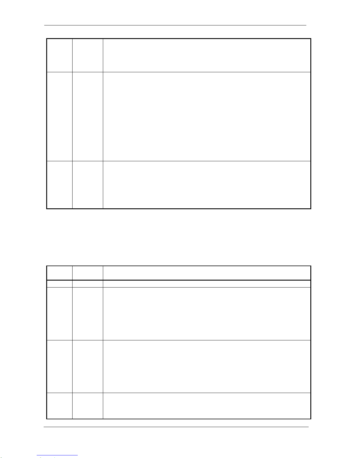
ProDAQ 3424 Function Card User Manual 3424-XX-UM
Copyright, 1998-2005 Bustec Production Ltd. Page 45 of 56
This bit selects between edge or level mode of the Analog Trigger.
0 : edge mode selected
1 : level mode selected
USAGE
The direction or condition of the trigger is selected using COMP_SEL
3:1
WO
ATCHN_ADDR – Analog Trigger Channel Address
These bits specify a channel the AT_THR1/2 will be applied to.
000 : card channel 1
001 : card channel 2
010 : card channel 3
011 : card channel 4
100 : card channel 5
101 : card channel 6
110 : card channel 7
111 : card channel 8
USAGE
Only one Analog Trigger channel can be enabled at the time.
0
WO
AT_UPD – Analog Trigger Update
This bit, when set, lunches the update of the Analog Trigger settings.
0 : update not launched
1 : update of the Analog Trigger launched
USAGE
Any write with AT_UPD bit set changes previous settings
If AT_UPD bit is cleared the write can still change THR2[11:4] bits
All Analog Trigger settings, except of the THR1 and THR2, can be updated only if AT_UPD bit is
set during write to the register. THR1 and THR2 can be changed independently of the AT_UPD bit
settings.
5.16. CHNxCFG – Channel x Configuration Register
These are registers used to configure front-end of channel ‘x ‘, where ‘x’ is in the range from 1 to 8.
Bit
Access &
Default
Description
15:12
Reserved
11:10
R/W
‘00’
GAIN2_SEL – Gain of the Second Stage Selection
These bits select the gain of the second PGA in the signal path.
00 : x1 gain
01 : x10 gain
10 : x100 gain
11 : not allowed
USAGE
Channel’s gain is defined as GAIN1 * GAIN2
9:8
R/W
‘00’
GAIN1_SEL – Gain of the First Stage Selection
These bits select the gain of the first PGA in the signal path.
00 : x1 gain
01 : x2 gain
10 : x5 gain
11 : x10 gain
USAGE
Channel’s gain is defined as GAIN1 * GAIN2
7
R/W
0
HPF_EN – High Pass Filter Enable
This bit enables ADC’s built in high pass filter.
0 : High pass filter disabled
1 : High pass filter enabled
Page 46
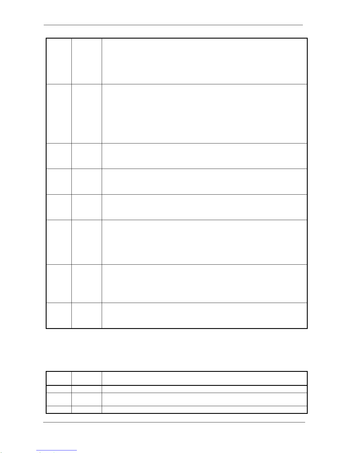
3424-XX-UM ProDAQ 3424 Function Card User Manual
Page 46 of 56 Copyright, 1998-2005 Bustec Production Ltd.
USAGE
This bit can be asserted in the registers assigned to odd channel numbers
and controls the high pass filter of that odd channel and consecutive even
channel
For even channel numbers the write to this bit does not change anything
while readout gives the status of the HPF_EN bit of the previous odd
channel
6
R/W
0
VREFGND_EN – VREF/GND Input Enable
This bit connects channels to VREF/GND voltage.
0 : channel input switched to front panel
1 : channel input switched to VREF/GND voltage
USAGE
Use only during calibration process
VREF_ON bit selects between VREF and Ground
When calibrating gain (VREF_ON bit switched to VREF voltage) try to
connect only one channel at the time for better accuracy
5
R/W
0
NEG_GND – Negative Input Grounded
This bit is used to ground the negative input.
0 : Negative input not grounded
1 : Negative input grounded
4
R/W
0
NEG_CPL – Negative Input Coupling Selection
This bit switches between AC and DC coupling for the negative signal path.
0 : AC coupling selected
1 : DC coupling selected
3
R/W
0
POS_CPL – Positive Input Coupling Selection
This bit switches between AC and DC coupling for the positive signal path.
0 : AC coupling selected
1 : DC coupling selected
2
R/W
0
TEDS_ON – TEDS Switched On
This bit is used to connect positive input channel to the TEDS memory reader
circuitry.
0 : positive channel input not connected to TEDS reader (normal operation)
1 : positive channel input connected to TEDS reader
USAGE
The bit from only one channel can be switched on at the time
1
R/W
0
ICP_ON – ICP Switched On
This bit allows to switch on ICP excitation current.
0 : positive channel input disconnected from ICP current regulator diode
1 : positive channel input connected to ICP current regulator diode
USAGE
The bit NEG_GND has to be set to close the loop of the ICP excitation
0
R/W
0
CHN_EN – Channel Enable
This bit is used to include the channel in the Data Acquisition process.
0 : channel disabled
1 : channel enabled
5.17. DDS_WX – DDS Word Register
This is DDS word register. It is used to set up words written to DDS during DDS update phase if
DDS is to be used.
Bit
Access &
Default
Description
15:11
Reserved
10:8
WO
WX_ADDR – Word X Address
The address of the word. WX_ADDR is in the range from 0 to 4.
7:0
WO
DDS_WX – DDS Word X
Page 47
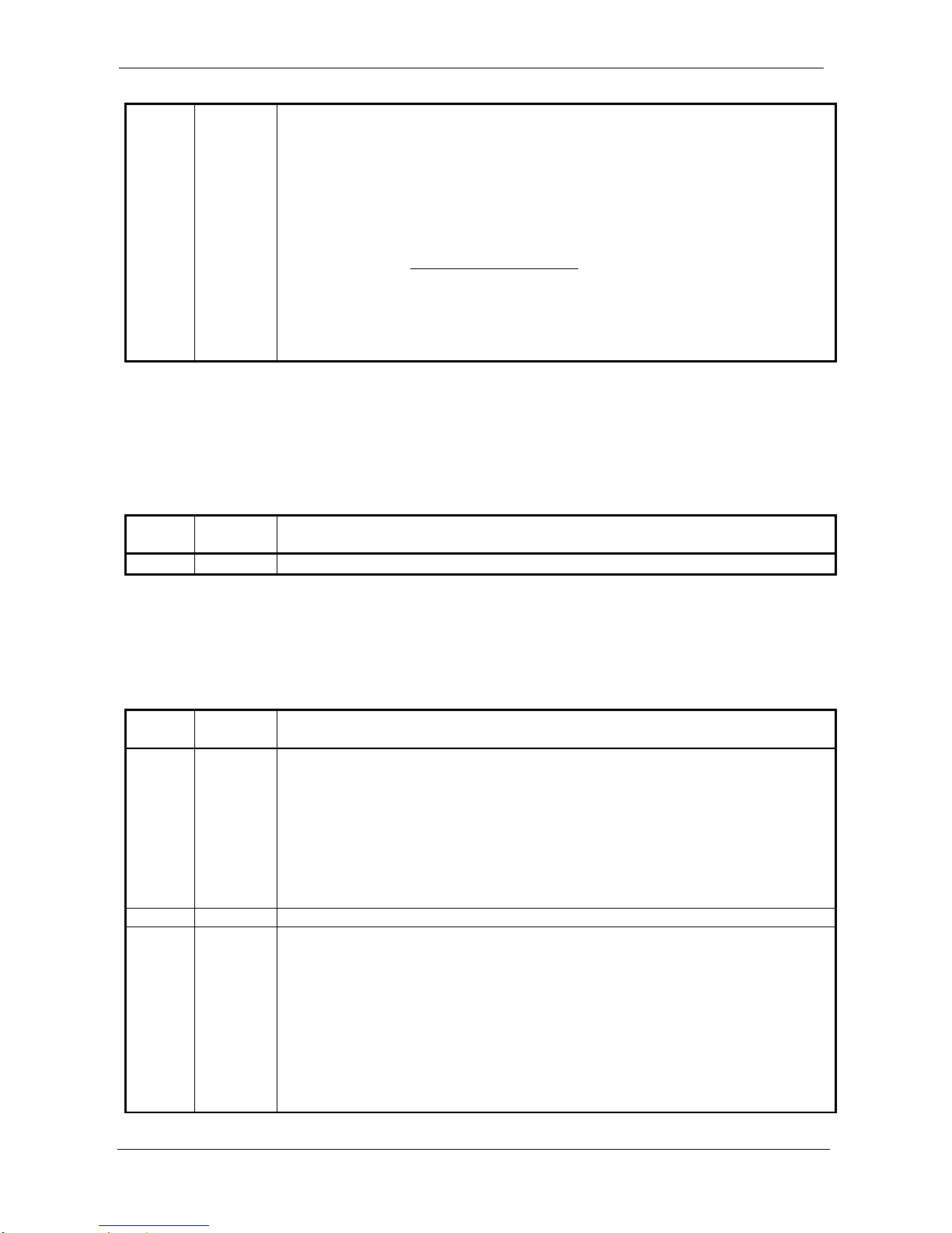
ProDAQ 3424 Function Card User Manual 3424-XX-UM
Copyright, 1998-2005 Bustec Production Ltd. Page 47 of 56
The content of the DDS word to be stored.
USAGE
The explanation of the DDS word meaning is given below:
W0 – on the 3424 card it should be all zeros. If DDS has to be
placed in power down then switch DDS 125 MHz clock off (disable PLL)
and DDS will automatically go to power down
W1 to W4 – they are parts of 32-bit frequency tuning word of DDS
circuit. DDS output clock frequency is defined as:
32
out
2
Clock SystemPhase
f
, where Phase is 32-bit frequency
tuning word W1W2W3W4, and system clock is 125 MHz.
The DDS circuitry was optimised to generate clock output with possibly low
jitter in the range of 12.5 MHz to 25 MHz. See chapter 3.3.4 for more
information on sampling settings.
5.18. DAC_DATA – DAC Data Register
This is offset correction DAC data register. Data stored in this register will be written to DAC
channel specified in DAC_ADDR register when a write operation to DAC_ADDR register takes
place.
Bit
Access &
Default
Description
15:0
WO
DAC_DATA – DAC Data
5.19. DAC_ADDR – DAC Address Register
This is offset correction DAC address register. After write operation to this register, the data stored
previously in DAC_DATA register will be written to the DAC channel specified on the DAC_ADDR
bits. The write starts only when the previous write access was finished (DAC_BUSY flag set to ‘0’).
Bit
Access &
Default
Description
15
RO
0
DAC_BUSY – DAC Busy
This is a status bit that indicates when the DAC is ready to accept next access. After
any access to DAC DAC_BUSY flag goes and stays high as long as the access is
not finished.
0 : board ready to accept next write to DAC
1 : board busy and writes to DAC_ADDR register will be ignored
USAGE
Directly after reset, DAC_BUSY flag is active for about 1ms until the
initialisation process is finished
14:3
Reserved
2:0
WO
DAC_ADDR – DAC Address
These bits specify the DAC channel the DAC_DATA will be written to.
000 : DAC channel A (card channel 1)
001 : DAC channel B (card channel 2)
010 : DAC channel C (card channel 3)
011 : DAC channel D (card channel 4)
100 : DAC channel E (card channel 5)
101 : DAC channel F (card channel 6)
110 : DAC channel G (card channel 7)
Page 48
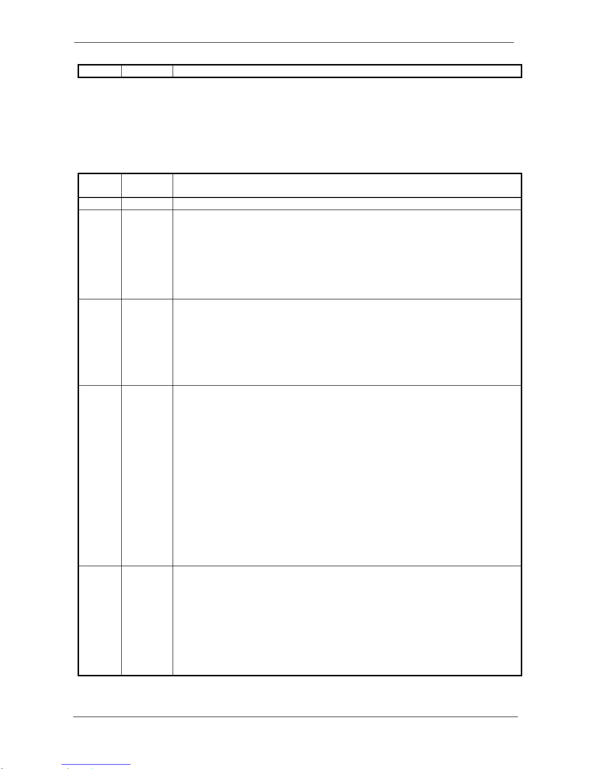
3424-XX-UM ProDAQ 3424 Function Card User Manual
Page 48 of 56 Copyright, 1998-2005 Bustec Production Ltd.
111 : DAC channel H (card channel 8)
5.20. TEDS_ACC – TEDS Access Register
This register gives the possibility to access the TEDS-enabled sensor’s memory. The interface is
based on the 1-WIRE link. For details on TEDS information stored in TEDS sensor refer to its
datasheet. Note that to access TEDS sensor connected to a particular channel, it must be
connected to the TEDS reader (bit TEDS_ON in respective CHNxCFG register set to ‘1’).
Bit
Access &
Default
Description
15:12
Reserved
11
RO
1
TEDS_READY – TEDS Ready
This bit indicates if the execution of an operation specified on the OP bits is finished.
0 : TEDS memory not ready, operation in progress
1 : TEDS memory ready and able to react on further actions
USAGE
This bit can be used by software in conjunction with TEDS_PRESENT bit to
determine whether any new accesses to TEDS memory can be initiated
Data read from CMD_DATA field is valid only when this bit is set to ‘1’
10
RO
0
TEDS_PRESENT – TEDS Present
This bit indicates if the execution of a RESET operation finished successfully.
0 : TEDS not present
1 : TEDS present and able to react on further actions
USAGE
This bit can be used by software in conjunction with TEDS_READY bit to
determine whether any accesses to TEDS sensor memory can be initiated
For description of TEDS sensor memory commands refer to its datasheet
9:8
WO
OP – Operation Selection
The Operation bits specify the action the TEDS interface logic shall do.
00 : No effect
01 : READ - Requests a read of one data byte from TEDS sensor memory. After
operation is completed (bit TEDS_READY set to ‘1’), software can read this
data from the CMD_DATA bits.
10 : WRITE - Requests a write of byte specified in the CMD_DATA field to the
TEDS sensor memory. Transmission of the next byte can be initiated after
operation is completed (bit TEDS_READY set to ‘1’).
11 : RESET - Initiates TEDS sensor memory Reset operation, which is necessary
before first access to TEDS memory and after some commands issued to it.
Next operation can be initiated after operation is completed successfully (bit
TEDS_READY set to ‘1’ and bit TEDS_PRESENT set to ‘1’).
USAGE
Attempts to start a new operation before operation previously initiated is
finished are ignored
For description of TEDS sensor memory commands refer to it’s datasheet
7:0
R/W
h
CMD_DATA – Command / Data
This is the command/address/data byte that will be transferred to the TEDS sensor
memory during WRITE operation or data read from memory after READ operation.
Write
Specifies the byte that has to be transferred to the TEDS memory during a Write
operation
Read
Gives the last data read from the TEDS sensor memory
USAGE
For description of TEDS memory commands refer to sensor datasheet
Page 49
ProDAQ 3424 Function Card User Manual 3424-XX-UM
Copyright, 1998-2005 Bustec Production Ltd. Page 49 of 56
5.21. GCOEFL – Gain correction coefficient write register, bits 15..0
GCOEFL register together with GCOEFH register can be used to overwrite gain correction
coefficient loaded during card initialisation from EEPROM. This can be useful for example when
different gain correction coefficients are needed for every gain selected. Software can read new
gain correction coefficients from EEPROM or it can write it’s own gain correction coefficient values.
Bit
Access &
Default
Description
15:0
WO
GCOEFL – Gain correction coefficient, bits 15..0
Used to store bits 15..0 of gain correction coefficient in internal temporary register
USAGE
Should always be used together with GCOEFH register. Write to GCOEFH
register causes that the part of a gain coefficient previously stored in
GCOEFL register is transferred together with bits 23..16 to internal gain
coefficients memory to location specified by GCOEF_CHN field.
5.22. GCOEFH – Gain correction coefficient write register, bits 23..16 and address
GCOEFH register together with GCOEFL register can be used to overwrite gain correction
coefficient loaded during card initialisation from EEPROM. This can be useful for example when
different gain correction coefficients are needed for every gain selected. Software can read new
gain correction coefficient to be written to GCOEFL and GCOEFH registers from EEPROM or it
can write it’s own gain correction coefficient values.
Bit
Access &
Default
Description
7:0
WO
GCOEFH – Gain coefficient, bits 23..16
Stores gain correction coefficient into internal gain coefficient memory at location
specified by GCOEF_CHN field.
USAGE
Should always be used together with GCOEFL register. Write to GCOEFH
register causes that the part of a gain coefficient previously stored in
GCOEFL register is transferred together with bits 23..16 to internal gain
coefficients memory to location specified by GCOEF_CHN field.
12:8
Reserved
15:13
WO
GCOEF_CHN – Gain correction coefficient write channel selection
Specifies the channel the gain coefficient is being written for:
000 : Channel 1
001 : Channel 2
010 : Channel 3
011 : Channel 4
100 : Channel 5
101 : Channel 6
110 : Channel 7
111 : Channel 8
5.23. EPD – EEPROM Data Register
This is EEPROM data register.
Bit
Access &
Default
Description
15:0
R/W
EEP_DATA – EEPROM Data
Page 50
3424-XX-UM ProDAQ 3424 Function Card User Manual
Page 50 of 56 Copyright, 1998-2005 Bustec Production Ltd.
h
This is a data word that will be transferred to the EEPROM memory during WRITE
operation or data read from memory after READ operation.
Write
Stores written data to be transmitted to EEPROM after WRITE command is
issued in EPC register
Read
Returns the data read from EEPROM after last READ command issued through
EPC register
5.24. EPC – EEPROM Control Register
This is EEPROM control register, used to read and write the EEPROM data. The EEPROM is used
to store calibration data and other manufacturing related information. The calibration data from
addresses 0 to 23 is used to initialise offset DAC and internal gain correction coefficients after
power-up or reset coming from a motherboard. Other locations not reserved for factory usage can
be used to store different sets of calibration coefficients for different gains. In this case, software
needs to read desired EEPROM locations and write offset coefficients to DAC and gain coefficients
to GCOEF registers.
Bit
Access &
Default
Description
15
RO
0
EEP_BUSY – EEPROM Busy
This is a status bit that indicates when the EEPROM is ready to accept next access.
After any access to EEPROM EEP_BUSY bit goes and stays high as long as the
access is not finished.
0 : board ready to accept next command
1 : board busy and writes to EPC register will be ignored
USAGE
Directly after reset this flag is active for about 1ms until the initialisation
process is finished
14
WO
RD_nWR – Read / Write
This bit is used to select desired EEPROM operation.
0 : WRITE to EEPROM
1 : READ from EEPROM
13:9
Reserved
8:0
WO
EEP_ADDR – EEPROM Address
This is address of the word location (range 0..511) in the EEPROM memory. The
map of the locations is given in Table 10.
Page 51
ProDAQ 3424 Function Card User Manual 3424-XX-UM
Copyright, 1998-2005 Bustec Production Ltd. Page 51 of 56
Word address
Information stored
0 (0x0)
1 (0x1)
2 (0x2)
3 (0x3)
4 (0x4)
5 (0x5)
6 (0x6)
7 (0x7)
8 (0x8)
9 (0x9)
10 (0xA)
11 (0xB)
12 (0xC)
13 (0xD)
14 (0xE)
15 (0xF)
16 (0x10)
17 (0x11)
18 (0x12)
19 (0x13)
20 (0x14)
21 (0x15)
22 (0x16)
23 (0x17)
24 . .383
(0x18 .. 0x17F)
384 .. 511
(0x180) .. (0x1FF)
The offset calibration coefficient for channel 1 (16 bits value).
The offset calibration coefficient for channel 2 (16 bits value).
The offset calibration coefficient for channel 3 (16 bits value).
The offset calibration coefficient for channel 4 (16 bits value).
The offset calibration coefficient for channel 5 (16 bits value).
The offset calibration coefficient for channel 6 (16 bits value).
The offset calibration coefficient for channel 7 (16 bits value).
The offset calibration coefficient for channel 8 (16 bits value).
Bits 23 to 16 of channel 1 gain calibration coefficient (on lower byte)
Bits 15 to 0 of channel 1 gain calibration coefficient
Bits 23 to 16 of channel 2 gain calibration coefficient (on lower byte)
Bits 15 to 0 of channel 2 gain calibration coefficient
Bits 23 to 16 of channel 3 gain calibration coefficient (on lower byte)
Bits 15 to 0 of channel 3 gain calibration coefficient
Bits 23 to 16 of channel 4 gain calibration coefficient (on lower byte)
Bits 15 to 0 of channel 4 gain calibration coefficient
Bits 23 to 16 of channel 5 gain calibration coefficient (on lower byte)
Bits 15 to 0 of channel 5 gain calibration coefficient
Bits 23 to 16 of channel 6 gain calibration coefficient (on lower byte)
Bits 15 to 0 of channel 6 gain calibration coefficient
Bits 23 to 16 of channel 7 gain calibration coefficient (on lower byte)
Bits 15 to 0 of channel 7 gain calibration coefficient
Bits 23 to 16 of channel 8 gain calibration coefficient (on lower byte)
Bits 15 to 0 of channel 8 gain calibration coefficient
Area for storage of calibration coefficients for different gains.
Organization defined by software requirements.
Reserved for factory use (should not be overwritten by the user)
Table 10 – EEPROM address map
5.25. FCSUB – Function Card Sub-Type Register
This is function card sub-type register useful for software to distinguish between versions of the
board.
Bit
Access &
Default
Description
15:8
RO
h
FCSUB_2CH – Sub-Type Second Character
Second ASCII character of the function card sub-type
7:0
RO
h
FCSUB_1CH – Sub-Type First Character
First ASCII character of the function card sub-type
5.26. FCSERH – Function Card Serial Number High Register
This register contains the upper 16 bits of the function card serial number.
Page 52
3424-XX-UM ProDAQ 3424 Function Card User Manual
Page 52 of 56 Copyright, 1998-2005 Bustec Production Ltd.
Bit
Access &
Default
Description
15:0
RO
h
FCSERH – Function Card Serial Number (upper part)
Upper 16 bits (FCSER[31:16]) of the function card serial number
5.27. FCSERL – Function Card Serial Number Low Register
This register contains the lower 16 bits of the function card serial number.
Bit
Access &
Default
Description
15:0
RO
h
FCSERL – Function Card Serial Number (lower part)
Lower 16 bits (FCSER[15:0]) of the function card serial number
Page 53
ProDAQ 3424 Function Card User Manual 3424-XX-UM
Copyright, 1998-2005 Bustec Production Ltd. Page 53 of 56
6. Technical Specification
ITEM
SPECIFICATION
Input characteristics
Number of channels
8
Type
Differential or single-ended, software selectable
Coupling
AC or DC, software selectable
Signal ranges
+/-10V
+/-5V
+/-2V
+/-500mV
+/-200mV
+/-100mV
+/-50mV
+/-20mV
+/-10mV
Analog filter type
4-th order Butterworth
Analog bandwidth
TBD fs without optional dectimation,
TBD fs with optional dectimation
Offset Error
TBD
Gain Error
TBD
Noise
TBD
AC coupling
1uF / 100V in series with input signal
Input impedance (DC coupled)
10 M nominal
Max. Input Voltage
TBD
Sampling
Resolution
24 bit
Type of ADC
Sigma-Delta
Sample rates
20 kHz to 216 kHz without optional decimation
as low as 200 Hz with decimation
programmable with sub-hertz resolution
Oversampling
32fs for 80 kHz < fs < 216 kHz
64fs for 40 kHz < fs < 108 kHz
128fs for 20 kHz < fs < 54 kHz
Decimation
10x, 100x or none, software selectable
Internal ADC decimation filter
characteristics
Passband: 0.4535 fs
Stopband: 0.5465 fs
Passband ripple:
+/-0.001 dB @ 128 oversampling,
+/-0.003 dB @ 64 oversampling
+/-0.007 dB @ 32 oversampling
Page 54
3424-XX-UM ProDAQ 3424 Function Card User Manual
Page 54 of 56 Copyright, 1998-2005 Bustec Production Ltd.
Stopband attenuation: 120 dB
Group delay: 63 1/fs
FIR decimation filter characteristics
(single stage)
Decimation factor: x10
Passband: 0.4 fs
Stopband: 0.5 fs
Passband ripple
Stopband attenuation 126 dB
Group delay: 40 1/fs
Digital I/O
Front Panel Sync/Trig Input/Output
Signal standard
Active polarity
Min. pulse width
Connector type
TTL
Software selectable for trigger, active low for
synchronization
25ns
SMB
Other Sync/Trig connections (signal
standard)
Motherboard and VXI trigger system (TTL)
Local synchronization link (TTL)
Clock Inputs (signal standard)
Front panel SMB type, software selectable
50 termination (ECL)
Motherboard trigger input lines (TTL)
Local synchronization link (LVDS)
Clock outputs (signal standard)
Front panel connector SMB type (ECL)
Motherboard trigger output lines (TTL)
Local synchronization link (LVDS)
Other
ICP® sensor support
TEDS (IEEE1154.4) support
64 kSamples FIFO
Power Consumption
TBD
Dimensions
230 x 106 mm
Weight
TBD
Operating temperature
0 C to 50 C
Storage temperature
-40 C to 70 C
Humidity
0-90%, non-condensing
Warm-up time
TBD
Page 55

ProDAQ 3424 Function Card User Manual 3424-XX-UM
Copyright, 1998-2005 Bustec Production Ltd. Page 55 of 56
7. The VXIplug&play Driver
8. Programming the ProDAQ 3424
Page 56

Bustec Production, Ltd.
World Aviation Park, Shannon, Co. Clare, Ireland
Tel: +353 (0) 61 707100, FAX: +353 (0) 61 707106
Bustec, Inc.
17820 Englewood Dr #14, Middleburg Hts, OH 44130, U.S.A
Tel. +1 440 826 4156, Fax: +1 440 826 4184
 Loading...