

Page 1
Class J Fuseblocks J600 Series
600 Volt, ⁄Ω™-600 Amps
Form No. J600 Series
Page 1 of 2
Data Sheet: 1114
Bussmann
®
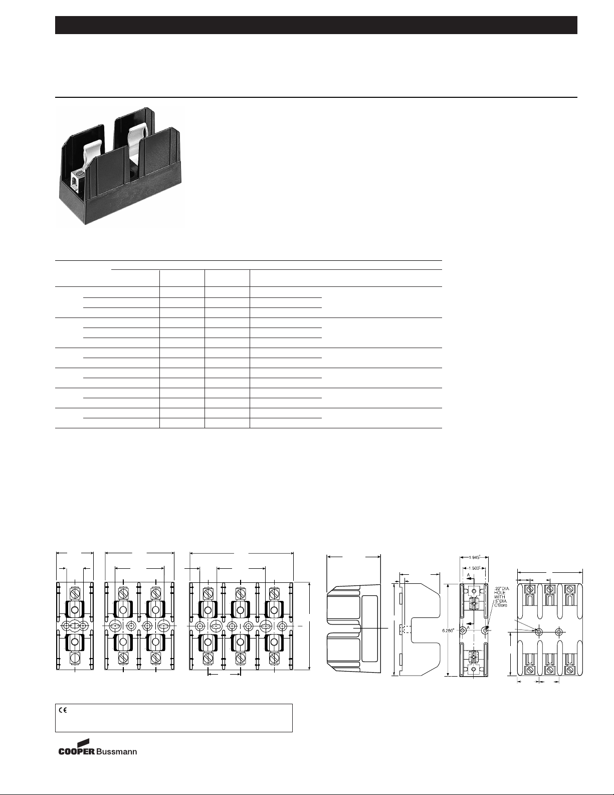
Dimensional Data All dimensions (±0.015)
Catalog Symbol: J600 Series
Ampere Rating: ⁄Ω™-600A
Voltage Rating: 600V
Withstand Rating: 200,000 RMS Sym. Amps
For use with Class J Fuses (Bussmann LPJ, JKS)
Agency Information:
UL Listed, UL 512, Guide IZLT, File E14853
CSA Certified, C22.2 No. 39, Class 6225-01, File 47235
UL Flammability: 94VO
Materials: Thermoplastic
.30"
2.28"
6.28"
.94"
.22"
Dia.
.5"
C'Bore
1 .583"
5"
3.14"
1.75"
1.5"
⁄Ω™-60A
61-100A
CE logo denotes compliance with European Union Low Voltage Directive
(50-1000Vac, 75-1500Vdc). Refer to Data Sheet: 8002 or contact
Bussmann Application Engineering at 636-527-1270 for more information.
3.202"
1.702"
FIGURE 1. FIGURE 2. FIGURE 3.
FIGURE 5.
FIGURE 4.
11-12-03
SB03116
Standard J Fuseblocks (600V) Catalog Data
Catalog Numbers
Pressure Box Box Lug w/ Fig. Wire
Amps Poles Screw† Plate† Lug Retaining Clip No. Range
1 J60030-1S
(2)
J60030-1P J60030-1C J60030-1CR†† 1 C, CR #2-14 CU, #2-8 AL
⁄Ω™-30 2 J60030-2S
(2)
J60030-2P J60030-2C J60030-2CR†† 2 COR #2-14 CU ONLY
3 J60030-3S
(2)
J60030-3P J60030-3C J60030-3CR†† 3 P, PR, S, SR #10-14 CU ONLY
1 — — J60060-1C J60060-1CR†† 1 C, CR, #2-14 CU/AL
31-60 2 — — J60060-2C J60060-2CR†† 2 COR #4-14 CU ONLY
3 — — J60060-3C J60060-3CR†† 3
61-100
1 — — — J60100-1CR 4 COR 1/0-8 CU ONLY
3 — — — J60100-3CR†† 5 CR, CRQ 1/0-8 CU/AL
101-200
1 — — — J60200-1CR 6 CR 250kcmil-6 CU/AL
3 — — — J60200-3CR 7
201-400
1 — — — J60400-1CR
(3)
8 CR 500kcmil -4 CU/AL
3 — — — J60400-3CR
(3)
9
401-600
1 — — — J60600-1CR 10 CR (2) 500kcmil-4/0 CU/AL
3 — — — J60600-3CR
(2)
11
†Clip reinforcing springs are standard on fuseblocks rated 100A and above. Available on 30A and 60A blocks by adding the letter “R” to the end of
the part number.
††Copper only connections available by changing “CR” suffix to “COR”.
(2)No UL, No CSA Certification
(3)UL Recognized, CSA Certification
4.702"
.750"
2.250"
750"
1.500"
2.250"
C
L
2.415"
4.005"
C
L
Page 2
Bussmann
®
Class J Fuseblocks J600 Series
600 Volt, ⁄Ω™-600 Amps
Form No. J600 Series
Page 2 of 2
Data Sheet: 1114
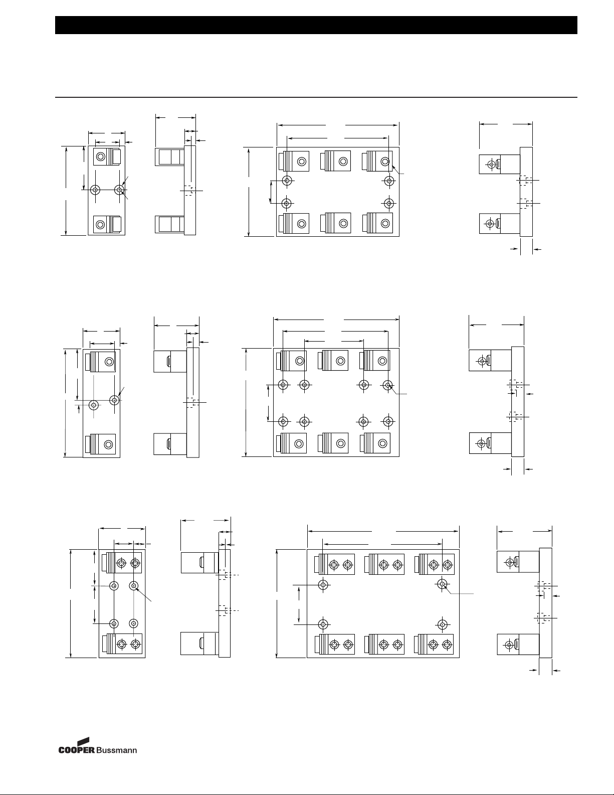
FIGURE 6.
101-200A
201-400A
401-600A
FIGURE 7.
FIGURE 8.
FIGURE 10.
FIGURE 9.
FIGURE 11.
All dimensions (±0.015)
The only controlled copy of this Data Sheet is the electronic read-only version located on the Bussmann Network Drive. All other copies of this BIF document are by definition uncontrolled. This bulletin is intended to clearly present comprehensive product data and provide technical information that will help the end user with design applications. Bussmann reserves the right, without notice, to change design or construction of any products and to discontinue or limit distribution of any products. Bussmann also reserves the right to change or update, without notice, any technical information contained in this bulletin. Once a product has been selected,
it should be tested by the user in all possible applications.
11-12-03
SB03116
3.06"
6.125"
3.5"
7.5"
.5"
3"
1.75"
3"
2"
.5"
.75"
c'bore
.34"
dia.
.625"
.75"
c'bore
.34"
dia.
3.1"
4"
.75"
.31"
6.125"
1.69"
1"
.56"
7.50"
2.00"
8.31"
7.00"
10.51"
9.00"
6.00"
.344" dia. hole through
.750 dia. c'bore
.344" dia. hole through
.750 dia. c'bore
3.15"
.750"
4.00"
.50"
4"
1.75"
3.25"
8.875"
2.375"
1.125"
.75"
c'bore
.34" dia.
4.99"
1"
.56"
8.875"
2.88"
14.144"
11.00"
1.00"
.344" dia.
hole through
.750 dia.
c'bore
4.99"
.50"
1.00"
 Loading...