

Page 1
Form No.
Page 1 of 1
BIF Doc #720006
Bussmann
®
The only controlled copy of this BIF document is the electronic read-only version located on the
Bussmann Network Drive. All other copies of this document are by definition uncontrolled. This bulletin
is intended to clearly present comprehensive product data and provide technical information that will
help the end user with design applications. Bussmann reserves the right, without notice, to change
design or construction of any products and to discontinue or limit distribution of any products.
Bussmann also reserves the right to change or update, without notice, any technical information contained in this bulletin. Once a product has been selected, it should be tested by the user in all possible
applications.
7-18-01
SB01191
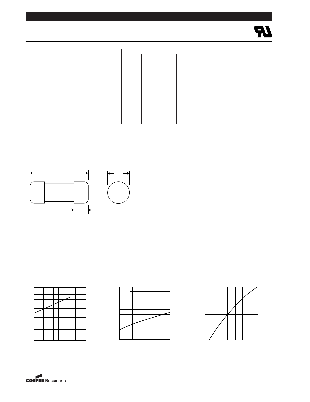
Ferrule
FWX 250V (U.L.) 1-30A
®
Dimensions
1.5
1.0
0.5
0.3
0.2
0.15
75 125 300200 250
E
g
K
U
L
1.4
1.2
10
3
800
600
500
400
300
200
50 100 150 200 250V
E
g
RMS
Kp
1.0
0.8
0.4
0.5
0.6
0.3
0.2
0.1
30 40 50 60
70
80 90 100%
I
b
50.8
(2.000")
15.5
(0.610")
14.3
(0.563")
Electrical Characteristics Ordering Information Dimensions Curves
Rated
I
2
t (A2S)
Carton
Current Clearing Watts Part Carton Weight Figure
Size RMS-Amps Pre-arc at 250V Loss Number Qty. (kg) Number BIF #
1 — — — FWX-1A14F
2 — — — FWX-2A14F
3 — — — FWX-3A14F
4 — — — FWX-4A14F
14 ≈ 51mm 5 1.6 13 1.3 FWX-5A14F 10 0.225 Fig. 1
(·Ω¡§∑) 10 3.6 24 3.4 FWX-10A14F
35785302
15 14 83 3.8 FWX-15A14F
20 33 200 4.6 FWX-20A14F
25 58 300 5.3 FWX-25A14F
30 100 500 5.9 FWX-30A14F
50 200 1800 5.7 FWX-50A14F
n Interrupting rating 200kA RMS Symmetrical. 1 kg = 2.2 lbs. 1 lb = 0.45 kg
n Watts loss provided at rated current.
n (250 Vdc/Interrupting rating 50kA) U.L. Recognition on 5 through 30 amperes only. Consult Bussmann for additional ratings.
n See accessories on page 90.
Fig. 1: 1-30 Amp Range
Dimension in mm.
1mm = 0.0394∑ 1∑ = 25.4mm
Total Clearing I2t
The total clearing I2t at rated voltage and
at power factor of 15% are given in the
electrical characteristics. For other voltages, the clearing I
2
t is found by multiplying by correction factor, K, given as
a function of applied working voltage,
E
g
, (RMS).
Arc Voltage
This curve gives the peak arc voltage,
U
L
, which may appear across the fuse
during its operation as a function of the
applied working voltage, E
g
, (RMS) at a
power factor of 15%.
Power Losses
Watts loss at rated current is given in
the electrical characteristics. The curve
allows the calculation of the power
losses at load currents lower than the
rated current. The correction factor, K
p
,
is given as a function of the RMS load
current, I
b
, in % of the rated current .
Electrical Characteristics
 Loading...