

Bussmann British Style BS 88 Accessories Catalog
Form No.
Page 1 of 1
BIF Doc #720037
Bussmann
®
The only controlled copy of this BIF document is the electronic read-only version located on the Bussmann
Network Drive. All other copies of this document are by definition uncontrolled. This bulletin is intended to
clearly present comprehensive product data and provide technical information that will help the end user
with design applications. Bussmann reserves the right, without notice, to change design or construction of
any products and to discontinue or limit distribution of any products. Bussmann also reserves the right to
change or update, without notice, any technical information contained in this bulletin. Once a product has
been selected, it should be tested by the user in all possible applications.
7-18-01
SB01191
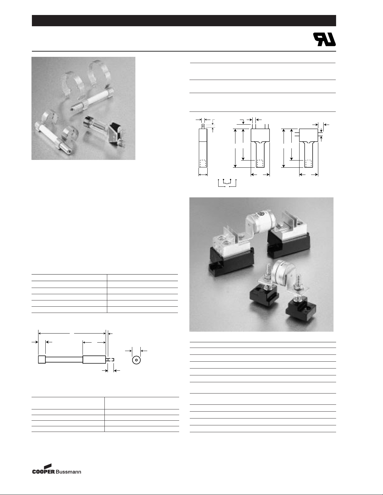
British Style BS 88 – Accessories
Indicator System and Fuse Bases (Blocks)
Trip-indicator fuselinks are available for use in parallel
with the main fuselinks. They can either be attached to
the associated fuselink or mounted separately in panel
mounted fuse clips, Part No. CL1. A push-on adaptor
and microswitch attachment is available for use with the
trip indicator to give the facility of remote indication,
reference MAI or MBI.
Fuse ratings of 20A and below cannot usually accommodate a trip fuselink in parallel.
Where trip indicator fuselinks are to be attached to the
main fuselink, an accessory pack comprising a pair of
mounting clips and an appropriate trip indicator fuselink
will be required.
The ordering code references for these packs are listed
below:
6
21
A
0.8
6.35
6
3.6
5.2
5.2
21
36
44
3.6
21
36
44
9.5
NC NC
NONO
Fuse Type Order Ref. Fuse Type Order Ref.
ET EC-600 FM MC-600
EET EC-600 FMM MC-600
FE EC-600 LMT MC-250
FEE EC-600 LMMT MC-250
LET EC-250
Trip-indicator Fuselink Data
Dim. ‘A’ Voltage Dim. ‘A’ Voltage
Type Max. Rating Type Max. Rating
TI250 37.6 250 TI1100 98.4 1100
TI500 47.5 500 TI1500 120.8 1500
TI600 55.7 600 TI2000 147.5 2000
TI700 61.8 700 TI2500 198.3 2500
Microswitch and Adaptor Type MAI
Current Rating:
AC 50/60Hz resistive load @ 250 VRMS 4A
AC 50/60Hz resistive load @ 127 VRMS 6A
DC, resistive load @ 110 Vdc 0.7
DC, resistive load @ 30 Vdc 2
Maximum Working Voltage:
Contact-to-contact (RMS) 1000V
Contact-to-contact (RMS) 1500V
Stud Fuseblocks
Part No. Stud Height Stud Dia. & Threads Max. Fuse Rating
C5268-1 1.00∑ fiΩ¡§-18 200A
C5268- 21.75∑ fiΩ¡§-18 200A
C5268- 30.75∑ fiΩ¡§-18 200A
C5268- 41.00∑ ⁄Ω¢-20 100A
C5268-5 1.75∑ ⁄Ω¢-20 100A
Universal Fuseblocks
Modular Max. Max. Fuse BIF
Base Voltage Current Rating Document
1BS101 600V 100A 1206
1BS102 600V 400A 1207
1BS103 600V 400A 1208
1BS104 600V 600A 1209
Dimensions in mm.
1mm = 0.0394∑ 1∑ = 25.4mm
Trip Indicator
Universal and Stud Fuseblocks
MAI or MBI
®
 Loading...