

Page 1
2-12-04
SB01018
Typical Voltage
Agency*
Rated Interrupting Pre-arcing Typical Total Clearing
3
Drop2Volts at
Information
Rated
Voltage Rating
1
I2t (A2Sec) I2t (A2Sec)
100% Rated
Current AC (Max.) DC6(Max.) AC DC
6
AC DC
6
AC DC
6
Current
⁄Ω™º
250V 250V 35A 35A 2.60 ≈ 10
-4
4.09 6.50 ≈ 10
-4
7.94 .67
••
⁄Ω¡§
250V 250V 35A 35A 2.40 ≈ 10
-4
7.60 ≈ 10-53.40 ≈ 10-42.12 ≈ 10
-4
10.41
••
⁄Ω¡º
250V 250V 35A 35A 5.50 ≈ 10
-4
4.77 ≈ 10-41.01 ≈ 10-31.27 ≈ 10
-3
6.00
••
⁄Ω•
250V 250V 35A 35A .003 .002 .69 .003 4.67
••
‹Ω¡§
250V 250V 35A 35A .008 .007 .84 .011 4.12
••
¤Ω¡º
250V 250V 35A 35A .011 .008 .74 .013 4.51
••
⁄Ω¢
250V 250V 35A 35A .015 .014 .38 .049 .89
••
‹Ω¡º
250V 250V 35A 35A .044 .040 1.57 .051 2.88
••
‹Ω•
250V 250V 35A 35A .091 .072 2.59 .118 4.59
••
4
fiΩ¡ºº
250V 250V 35A 35A .12 .09 2.78 2.67 2.67
••
⁄Ω™
250V 250V 35A 35A .28 .24 2.75 1.41 .59
••
‹Ω¢
250V 250V 35A 35A .82 .80 3.69 1.49 .37
••
1 250V 250V 35A 35A 1.50 1.44 5.21 2.87 .31
••
1
⁄Ω¢
250V 250V 100A 100A 1.95 2.14 10.69 9.66 .35
••
1
⁄Ω™
250V 250V 100A 100A 3.44 3.80 16.41 19.08 .27
••
2 250V 250V 100A 100A 5.4 — 22.14 — .28
••
2
⁄Ω¢
250V 250V 100A 100A 6.0 5.93 19.04 15.70 .26
••
2
⁄Ω™
250V 250V 100A 100A 5.3 7.36 19.70 14.67 .31
••
3 250V 250V 100A 100A 12.19 13.25 27.29 24.07 .25
••
4 250V 250V 200A 200A 25.08 27.57 74.91 51.20 .22
••
5 250V 250V 200A 200A 7.08 7.19 39.80 22.70 .23
••
6 250V 250V 200A 200A 10.52 11.60 59.49 30.60 .23
••
7 250V 250V 200A 200A 13.27 14.20 67.68 42.30 .23
••
8 250V 250V 200A 200A 24.56 25.59 104.90 55.81 .19
••
9 250V 250V 200A 200A 211.00 205.33 238.40 274.00 .18
••
10 250V 250V 200A 200A 240.30 268.00 315.70 322.00 .20
••
15 32V 32V 1000A 1000A 577.00 691.00 .14
••
20 32V 32V 1000A 1000A 1241.00 1450.00 .12
••
25 32V 32V 1000A 1000A 2276.00 2588.00 .11
••
30 32V 32V 1000A 1000A 3812.00 4098.00 .12
••
*
Information: UL Listed, Std. 248-14, Guide JDYX, File E19180; CSA Certification,
Class 1422-01, File 53787; AGC & AGC-V UL Recognized, Guide JDYX2, File E19180.
1. Interrupting ratings were measured at 70%-80% power factor on AC, and at a time constant
described in UL 198L.
2. Voltage drop was measured at 25
°C ± 3°C ambient temperature at rated current.
3. I
2
t was measured at listed interrupting rating and rated voltage.
4. Interrupting rating for AGC ⁄Ω∞ºº-10A @ 125V is 10,000A. Interrupting rating listed corresponds
to maximum rated voltage.
5. The AGC-10A fuse is self-certified for 32Vdc at 1000 AIC.
6. Other available sizes include: ⁄Ω∞ºº, ⁄Ω™ºº, ⁄Ω¡ºº, ⁄Ω∞º, ⁄Ω£™, ⁄fi/¡ºº, ⁄‡fi/¡ººº, ⁄Ω£, ›/¡º, fl/¡º, °/¡º, 1¤/¡º,
1‹/¡º, 1fl/¡º, 1‹/¢, 1°/¡º, 3¤/¡º, 3⁄Ω™, 4⁄Ω™, 6⁄Ω¢, 7⁄Ω™, 12 and 14.
7. DC ratings are self-certified.
UL
U.R.
CSA
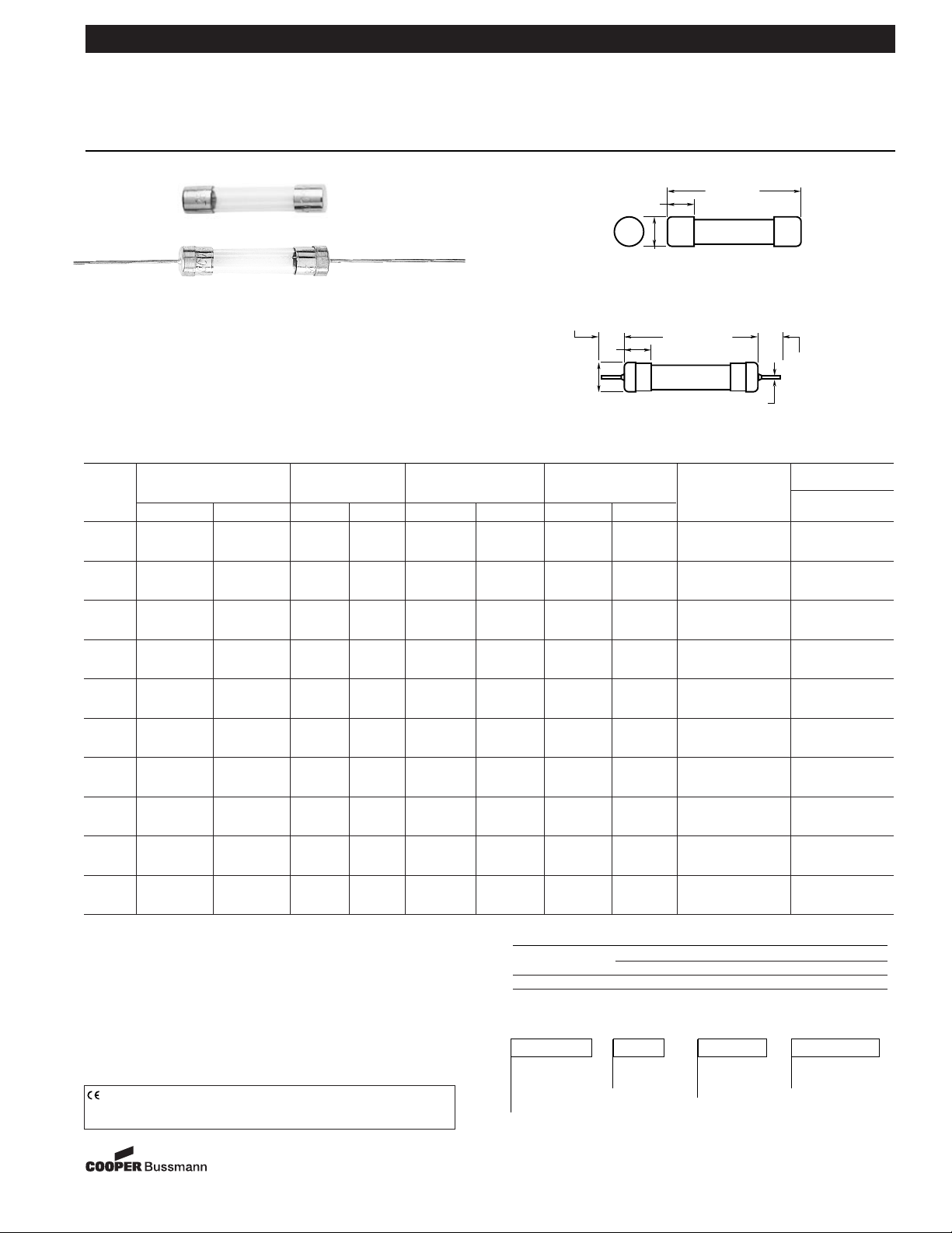
Electrical Characteristics
Fast-Acting Glass Fuses AGC
For ⁄Ω¢∑ ≈ 1⁄Ω¢∑ (6.3mm ≈ 32mm) AGC-V
Form No. AGC
Page 1 of 2
Data Sheet: 2001
Bussmann
®
Packaging & Ordering Information:
Package Code Product Lead Rated Current
Blank
5 in Symbol Blank -no lead
BK/
100 in V-Axial lead
(See Table)
VAGC
Catalog Symbol: AGC (3AG)
Fast-Acting
*Agency Information:
UL/CSA 248-14
Construction: Glass Tube
Nickel-Plated Brass Endcaps
Time-Current Characteristics
Rated
Percent of Rating
Current
110% 135% 200%
⁄Ω™º-30 4 hrs. (min) 60 min. (max) 120 sec. (max)
Dimensional Data
––
CE logo denotes compliance with European Union Low Voltage Directive
(50-1000Vac, 75-1500Vdc). Refer to Data Sheet: 8002 or contact
Bussmann Application Engineering at 636-527-1270 for more information.
.25"
6.35mm
.25"
(±0.003)
6.35mm
"
1.500
38.10mm
(REF)
1.292"±.031
32.82mm±.79
.266"
6.76mm
1
/20—15 AMP: .032"
.81mm
20—30 AMP: .040
1.02mm
1.25"
(±0.031)
31.85mm
"
(REF)
(REF)
1.500"
38.10mm
(REF)
Page 2
Fast-Acting Glass Fuses AGC
For ⁄Ω¢∑ ≈ 1⁄Ω¢∑ (6.3mm ≈ 32mm) AGC-V
Bussmann
®
Form No. AGC
Page 2 of 2
Data Sheet: 2001
The only controlled copy of this Data Sheet is the electronic read-only version located on the Bussmann Network Drive. All other copies of this document are by definition uncontrolled. This bulletin is
intended to clearly present comprehensive product data and provide technical information that will help the end user with design applications. Bussmann reserves the right, without notice, to change
design or construction of any products and to discontinue or limit distribution of any products. Bussmann also reserves the right to change or update, without notice, any technical information contained in this bulletin. Once a product has been selected, it should be tested by the user in all possible applications.
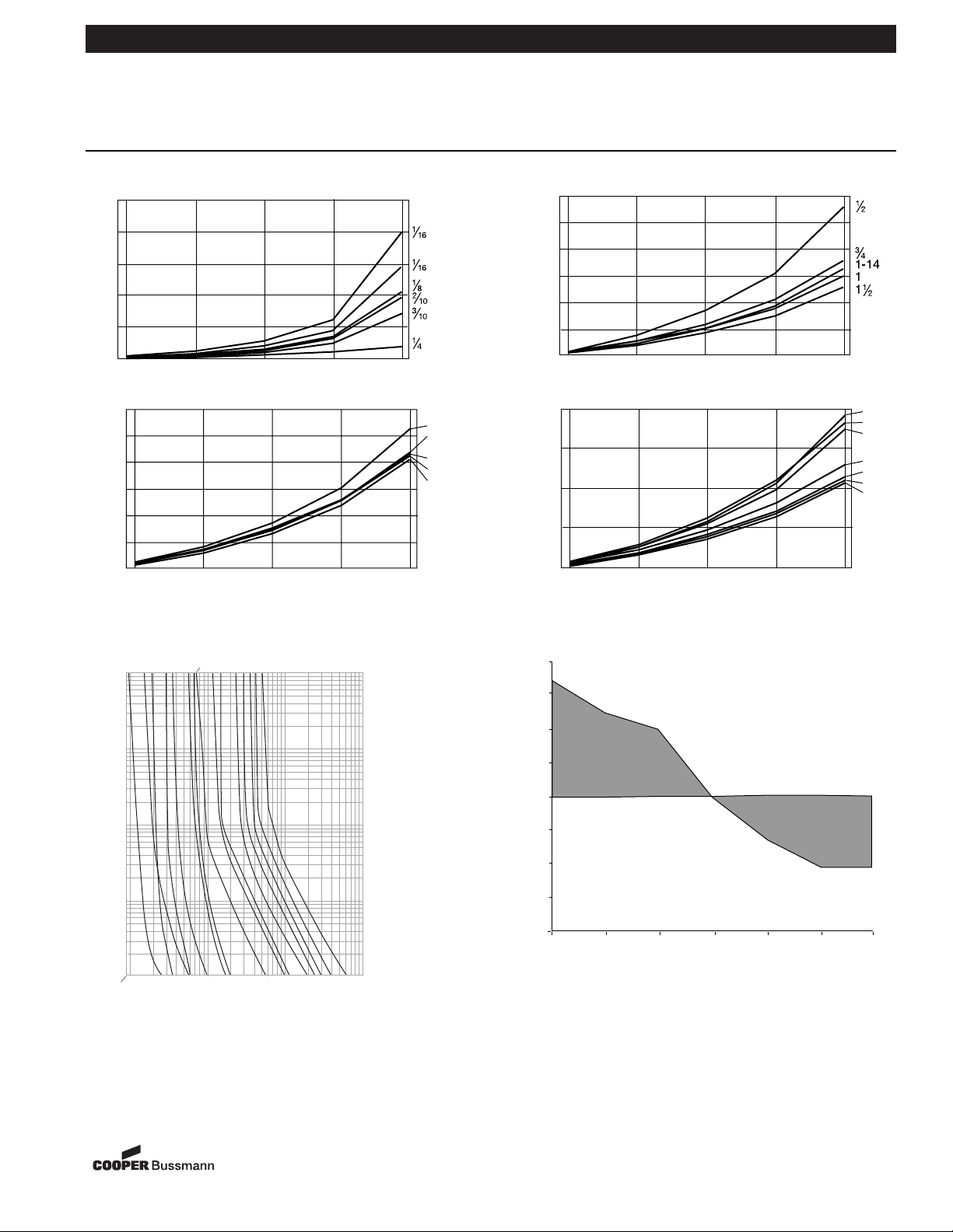
2.0 Ambient Temperature Effect Chart (Derating Curve)
Time-Current Characteristic Curves–Average Melt
(Full Size Curves Available)
1.0 Typical Voltage Drop (At 25°C Ambient Temperture)
2-12-04
SB01018
10
8
6
4
VOLTAGE DROP
2
0
5%
25%
PERCENT OF RATED CURRENT
50% 75% 100%
.6
.5
.4
.3
.2
VOLTAGE DROP
.1
0
5%
PERCENT OF RATED CURRENT
25%
50% 75% 100%
.3
.25
.2
.15
2
3
7
5
4
.1
VOLTAGE DROP
.05
0
5%
25%
50% 75% 100%
PERCENT OF RATED CURRENT
AMPERE
100
1/2
2/10
6/10
2-1/2
3/10
1/8
3/8
1/4
1/10
1/16
10
1
2
3
4
3/4
1-1/2
RATING
.2
.15
.1
.05
VOLTAGE DROP
0
5%
25%
50% 75% 100%
PERCENT OF RATED CURRENT
120
115
110
105
100
95
10
15
20
25
30
8
9
90
TIME IN SECONDS
.1
85
PERCENTAGE OF RATED CURRENT
80
-60 -30 0 25 50 80 100
AMBIENT TEMPERATURE °C
.01
.09
.1
1
10
100
CURRENT IN AMPERES
 Loading...