

Page 1

Host
Adapter Quick Installation
Page 2
Host Adapter
Quick Installation
Introduction
The
EISA
Host Adapter is an
intelligent EISA to SCSI bus master host adapter, supporting up to seven SCSI devices. BT-747C adapters
offer device driver support for widely-used industry
standard operating systems. The BT-746C is the same
as the BT-747C but without the floppy connector.
Installation Checklist
Host adapter installation involves the following steps:
2.
3.
4.
5.
6.
7.
8.
9.
Unpacking the host adapter and opening up the
host system for adapter and SCSI device installation.
Setting the SCSI ID for all devices being attached to
the host adapter.
Terminating SCSI devices.
Installing and cabling the adapter and SCSI devices.
Updating your host system CMOS.
Configuring EISA utility parameters.
Configuring optional adapter operating parameters
using the onboard
configuration utility.
Testing adapter connectivity.
Low-level formatting and verifying the hard
drive(s) (if needed).
10. Setting up the hard drive(s).
11. Installing the device drivers onto the hard drive(s).
Step 1. Unpacking
1.
Before handling the BT-747C, make sure your body
is grounded with a grounding strap. Touch your
computer on a metal part to discharge static electricity before handling the board. The board should
always be held by the edges even after static electricity is discharged.
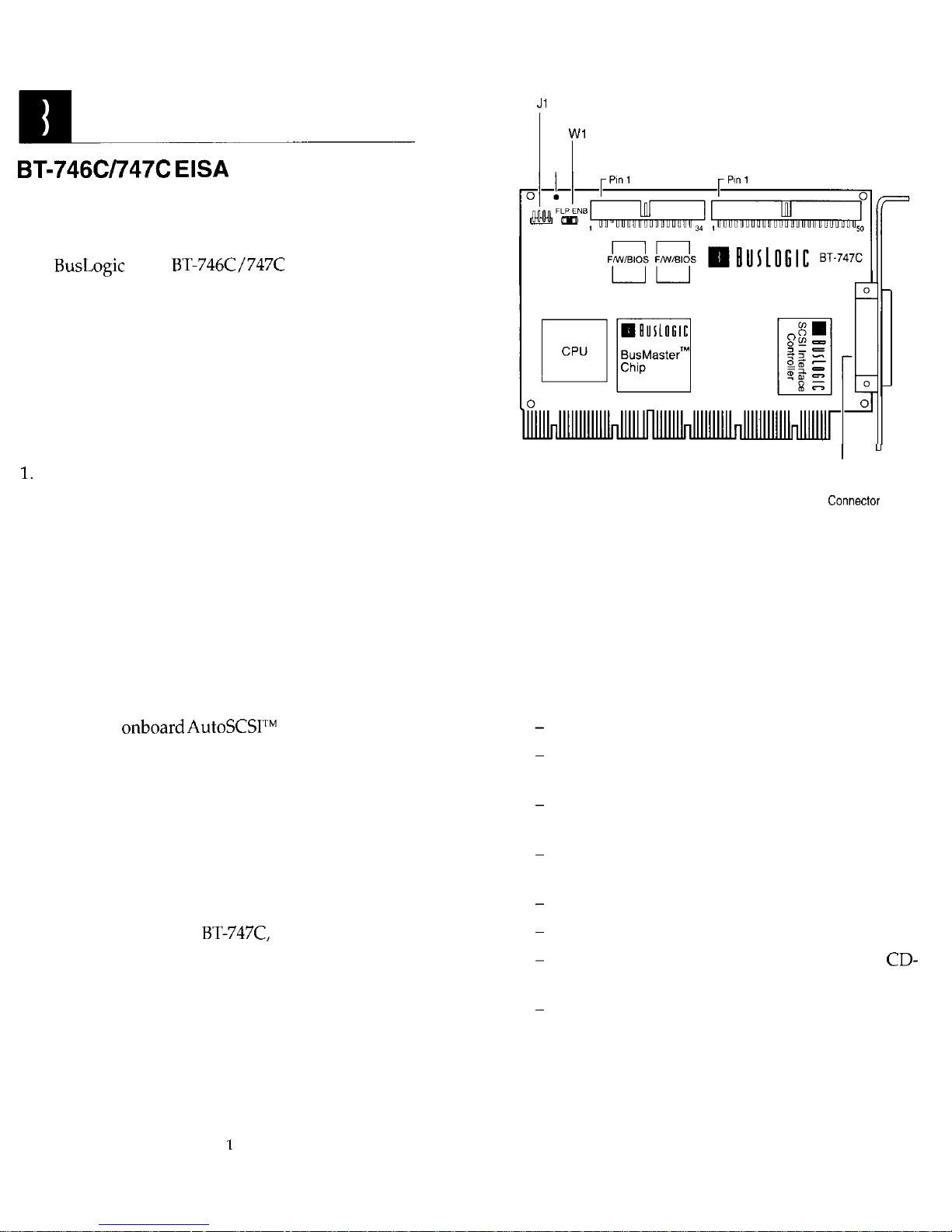
LED Connector
LED J2 Floppy Connector
J3 Internal SCSI Connector
Edge Connector
J4 External
SCSI
(SCSI 2)
Figure 1. BT-747C Board Layout
2.
Verify that no physical damage occurred during
shipping by inspecting the board for bent pins,
loose parts, broken traces, and chipped or broken
connectors.
You may need the following items during installation:
Small screwdriver and small needle-nosed pliers
50-pin SCSI flat ribbon cable to connect to inter-
nal devices
50-pin cable with high density connector to at-
tach to external devices
34-pin flat ribbon cable to connect to a floppy
drive. (BT-747C only)
Optional 4-pin cable to connect to the drive LED
Your computer’s hardware manual
Manuals for SCSI devices (e.g., hard drive,
ROM or tape player)
Computer (e.g., SETUP) and operating system
(partition, high-level format) programs
Page 3
3.
Power down the host system.
4.
Referring to your computer owner‘s manual, open
the case to gain access to the motherboard and expansion slots.
Step 2. Setting the SCSI Device ID
Each SCSI device must be assigned a unique SCSI ID
ranging from 0 through 7. Most SCSI peripheral devices are shipped with a pre-assigned SCSI ID. Your
Logic adapter is set to SCSI ID 7 by default.
Note: The SCSI
for your boot drive must be lower than
other drives. BIOS scans from ID 0
the boot drive.
If needed, change the SCSI ID for the peripheral devices as recommended in the owner’s manual. To change
the adapter’s SCSI ID, use the
Host Adapter SCSZ ID
op-
tion on the AutoSCSI Configuration Menu (Step 7).
Step 3. Terminating SCSI Devices
The first and last SCSI devices connected together on a
SCSI bus must have terminators installed or enabled.
Terminators, which can be connected to either SCSI devices or SCSI cables, are required for reliable operation
of the SCSI bus. If more than two SCSI devices are connected in a SCSI daisy chain, you must remove the terminators on the middle device(s).
If the BT-747C is not being installed at either end of the
SCSI bus, disable its terminators by using the Adapter
SCSI Terminators ON option on the AutoSCSI Configuration Menu (see Step 7).
Step 4. Installing and Cabling the Adapter
Before installing the adapter, you must check that the
jumper cap is installed on
This jumper enables
communication with the floppy drive.
1.
2.
Remove the mounting screw and the existing
bracket from the rear panel behind the 32-bit slot
where you want to install the BT-747C.
Press the BT-747C downward into the selected
bit slot, align the mounting bracket, and reinstall
the mounting screw. Make sure that the board is
properly seated in the slot.
3.
4.
5.
6.
7.
Connect the 50-pin SCSI cable to the adapter’s single-ended SCSI connector, J3, attaching the other
end to the SCSI device connector.
If connecting to a floppy drive, insert the 34-pin
floppy cable from the floppy drive into the floppy
connector
(BT-747C only).
Insert the optional four-pin header connector for
the drive activity LED on the front panel of the host
to connector
on the BT-747C. This connector may
be plugged into
either way.
Verify that all connections are secure.
Reattach and close the cover of the host computer
as described in the system owner’s manual.
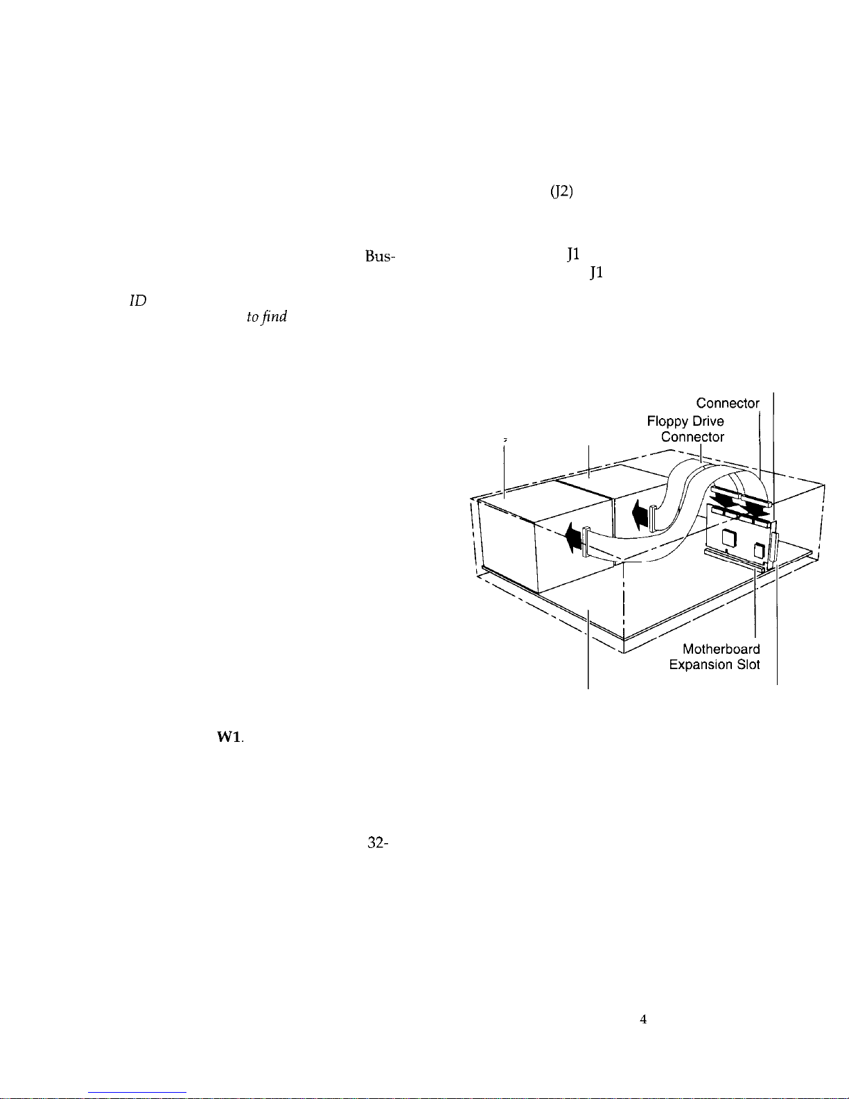
BT-747C
Internal
SCSI
Drive
Floppy internal SCSI
Disk
Drive
System External SCSI
Motherboard Connector
Figure 2. BT-747C Installation
Step 5. Updating System CMOS
1.
Once hardware installation is complete and the host
computer is reassembled, power up the system.
2.
Run SETUP and configure the host CMOS RAM options. Set the drive type option for the SCSI drive to
No Hard Drive Installed.
3.
Reset the system to activate your SETUP changes.
Page 4
Step 6. Using the EISA Utility
For most installations, the adapter will operate successfully
with its factory-default configuration. It may need to be
changed if
conflicts occur.
further configura-
tion is required, use the ElSA configuration utility or the
AutoSCSl utility described under Step 7.
The BT-747C fully supports the EISA automatic configuration facility. Every BusLogic EISA adapter comes
with a floppy diskette containing the
config-
uration file
Before starting, perform the following steps:
Copy the
!BUS4202CFG file onto the configuration floppy diskette provided with your host
system computer.
Place the configuration floppy diskette into your
system floppy drive and type “CF” (or the name of
your configuration program).
Follow the directions on your screen to select the
configure computer option. An Auto Added prompt
will advise you that the BT-747C has been installed
into a previously empty EISA slot.
Follow the directions on your screen to select the
BT-747C.
The default settings for configuration options are
shown on the screen. Select the desired options by
moving the cursor to the desired field and then press
<Enter>. A submenu for the options selected will appear. To set the option in the submenu, use the cursor
keys to highlight the selection and then press <Enter>.
Before operating the BT-747C, verify that the configuration settings have been set according to the target system’s operating requirements. Once completed,
proceed to Step 7.
Host
Port Address. This setting lets you define the
base I/O address of the three registers within the host
I/O map. Note that each board within the same EISA
host system must have its unique I/O register address-
es to prevent hardware conflicts.
Host Interrupt Request. This setting specifies the hard-
ware interrupt line on the EISA bus that the BT-747C
should use to generate interrupts to the host, or to disable interrupts. Edge-triggered interrupts assert inter-
rupts high; whereas, level-triggered interrupts assert
interrupts low. Level-triggered interrupts allow multiple boards to share the same hardware interrupt line on
the EISA bus.
Host BIOS (16K Bytes) Address. If more than one host
adapter is installed within the same EISA host system,
one must have the BIOS enabled.
ISA DMA Channel Emulation. It is only used by some
device drivers that require DMA emulation.
EISA Bus Burst Cycles. The BT-747C is capable of
transferring data across the EISA bus in bus master
burst mode reaching the maximum EISA data rate of 33
able the bus master burst mode feature depending
upon the capability of the motherboard. (Def=Disable)
Floppy Subsystem. When the floppy subsystem is disabled, the floppy disk controller will disregard read
and write commands. When the floppy subsystem is
enabled, the floppy disk controller is allowed to respond to read or write requests. (Def=Disable)
Step 7. Using the Onboard Configuration
Host adapter configuration is optional. You may skip
the following and proceed to Step 8.
For most card installations, the factory settings are suitable for successful operation. You can, however, further
configure the BT-747C to suit your operating environment, using the AutoSCSI Utility described below.
The AutoSCSl Utility
Every BT-747C comes with an
configuration
utility, AutoSCSI, which resides in Read Only Memory
(ROM). AutoSCSI is available when the system is first
powered up and at every system reset. Press Ctrl-B at
the system prompt.
Use AutoSCSI to set or change SCSI and BIOS-related
parameter configuration. AutoSCSI also offers diagnostic and disk utilities.
Tip:
needed, use the Auto Config All Adapters option on the AutoSCSl Configuration Menu to return the
adapter to its factory default values.
Page 5
Adapter Configuration
Host Adapter Interrupt Channel (IRQ). This value is
set using the EISA configuration utility.
ISA DMA Channel Emulation. See EISA configura-
tion description.
DMA Transfer Rate. This option does not apply to this
product.
Host Adapter SCSI ID. Use this option to change the
adapter’s SCSI ID on the SCSI bus.
SCSI Parity On. This setting determines whether pari-
ty on the SCSI bus is detected by the adapter or not.
Host Adapter SCSI Terminators On. This setting allows you to enable or disable host adapter SCSI termination. Only terminators on devices at both ends of the
SCSI chain should be turned on.
Device Configuration
Enable Sync Negotiation. Use this option to enable or
disable the synchronous data transfer negotiation between the host adapter and each SCSI device connected
to the SCSI bus.
Enable Disconnection. Use this option to enable or disable SCSI disconnection on each target device. When
enabled, it allows SCSI devices to perform seek operations in parallel and thus improve overall SCSI bus performance.
BIOS Sends Start Unit Command. This option allows
you to identify the SCSI devices whose motor spin up
is sequentially controlled by BIOS at power-up.
Ignore in BIOS Scan. This option excludes selected
drives from BIOS scan and registration. (Def=No)
Advanced Configuration
Host Adapter BIOS Enabled. This read-only field displays whether BIOS is enabled or disabled for this
adapter.
Host Adapter BIOS Uses INT 19 for System Boot. This
option allows you to include or exclude the adapter on-
board BIOS in the DOS boot process.
Host Adapter BIOS Supports DOS Space
This
option enables the adapter onboard BIOS to support up
to 8 Gigabytes per drive of DOS disk space. The
support must be turned on under the following two
conditions: (1) the combined space of all the DOS parti-
tions exceeds 1 GByte or (2)
1 GByte disk accesses are
required to boot the operating system.
BIOS Supports Removable Disks as Fixed Disks.
This
option enables the adapter BIOS to register removable
disks as fixed disks and access them via Interrupt 13H.
BIOS Supports
2 Drives (DOS 5.0 or Above). This
option turns on BIOS support for more than two hard
disk devices on the SCSI bus.
Support Immediate Return on Seek.
Enabling this option allows BIOS to return completion status immediately without executing the seek operation.
Support Floptical Drive. When this option is enabled,
BIOS registers and controls floptical devices. (Def=No)
Enable SCSI Bus Reset. When this option is enabled,
the adapter asserts a SCSI bus reset signal upon detecting a hard reset.
Reserved RAM for BIOS access (Segment: Offset) 0.
Use this option to allocate system memory for BIOS parameter storage.
Step 8. Testing Adapter Connectivity
Use the
Test on l/O Port option on the AutoSCSI
Diagnostics Menu to test adapter connectivity to the
motherboard. This test writes and reads data between
the adapter and the motherboard. Press
to end
the test.
Step 9. Formatting the Hard Drive
Because most off-the-shelf hard drives are factory formatted, it is unlikely that you need to perform this pro-
cedure and you may proceed to Step 10. If, however,
you have an un-formatted disk, or if you are experiencing problems with your hard drive that indicate the
need for a low-level format, use the Format
Disk
option
on the AutoSCSI Utilities Menu.
Caution: This procedure will erase everything on your
drive. Back up your hard drive before proceeding.
You cannot stop the format once it is started. When
completed, you may run the
Disk option to check
the format.
7
8
Page 6

Step 10. Setting Up the Hard Drive
You will need to take the following steps to configure
your hard drive for operation:
n
Create a partition on the drive for your operating
system and high-level format the drive.
n
Install the operating system.
These procedures differ depending on the operating
system you are installing. Refer to your operating system documentation for details.
Step 11. Installing the Device Driver
Device drivers are needed to allow devices attached to
the adapter to be recognized by and operate with the
operating system. In some cases, the operating system
has embedded or built-in support for basic hard drive
configurations. This means you can install up to a specific number of hard drives without having to install
additional device driver software. If you are installing
hard drives beyond the limit of built-in support, you
will need to install additional drivers. You will also
need to install device drivers when installing devices
such as CD-ROM or tape backup drives, etc.
When you install the device drivers available from Bus-
Logic, you will have support for:
n
Up to four
host adapters
n
Up to seven SCSI peripheral devices (hard drives,
etc.)
n
Connectivity to SCSI tape drives, magneto optical
(MO) disk drives and CD-ROM drives and other
devices. Any additional drivers required for operat-
ing these devices are included with the device.
DOS and NetWare Auto-Install
To install the DOS and NetWare drivers using the auto-
mated utility included with your device driver software, do the following:
1.
If you had not already done so, insert the floppy
diskette containing the device drivers into the flop-
py drive and enter: install
2.
You are prompted to indicate the drive containing
the floppy or press <ENTER> to accept the default.
3.
You are next prompted to select the driver (DOS or
NetWare) to be installed. Move the cursor to the de-
sired selection and press <ENTER>.
The system allows you to select Express Install or
Custom Install. If you select Custom Install, the system lets you select the specific drivers to be installed.
The utility automatically installs the drivers. Once
installed, you will be asked if you want the utility to
automatically update your system
and
au-
files. You can have the system rename your
old configuration files for you or you can select
your own name for them. If you want to update
your configuration files manually, select the
Skip
This Step
option.
Once installation is complete, re-boot your system
to activate the new device drivers. You won’t be
able to access the new devices until you do so.
Refer to the BusLogic SCSI Adapter Driver Software ln-
stallation Guide
or third-party documentation for device
driver installation details.
Troubleshooting
Be sure all connectors are firmly seated.
Check that the adapter and attached devices have
unique SCSI
Check cable orientation. Be sure that Pin 1 on the ca-
ble matches
on the SCSI device connector.
Be sure that the SCSI ID for the boot hard drive is
lower than any other drive. BIOS determines the
boot drive by scanning SCSI devices starting from 0.
If the boot drive number is higher than the other
drive, change it to a lower value.
If the BT-747C is in the middle of the SCSI chain,
use AutoSCSI to disable termination.
Check that you have correctly set the hard drive to
not installed in your system SETUP file.
Be sure that settings for the adapter IRQ, I/O Port
Address and BIOS Address do not conflict with other installed cards.
If necessary, repeat the steps to format, partition
and install the operating system on the hard drive.
Be sure to backup the drive before proceeding.
Page 7

Check that you’ve installed all the correct drivers
for your operating system and attached devices.
Warranty Information
If damage to the board has occurred, return it in the
protective envelope and original packaging with this
manual to your BusLogic board supplier. The shipping
agent should also be notified if the unit has been damaged during shipment.
Specifications
Dimensions
x 4.5L” x
Electrical
Operating
Voltage
Operating Current
Max. Ripple/Noise
Max.
100
Environmental
Temperature
Relative Humidity
Altitude
0°C to 60°C (32°F
‘40°F)
10% to 95%
0 to 10,000 ft. operating
0 to 15,000 ft. non-operating
Interface Connections
SCSI Internal 50-pin double-row connector
SCSI External 50-pin shielded SCSI connector
ribbon style
(BT-747C only)
To/From System
standard edge connector
MTBF
90.000 hours
Meets requirements of FCC Part 15, Class B.
Inc.
4151 Burton Drive
Santa Clara, CA 95054
3002513 REV. A
 Loading...