

Page 1
2010
Page 2

Welcome
Thank you for selecting the ST-104 Rotary Mower. Your machine has been carefully inspected by both the factory and the dealership prior to being received by
you to ensure that it is ready for operation.
This manual explains the proper operation of your machine. It is very important
that you read and understand these instructions before operating or maintaining
the machine. Failure to do so could result in personal injury or even death to you
or passersby. Consult your Bush-Whacker dealership if you do not understand the
instructions in this manual or need additional information.
Hall Manufacturing, Inc. reserves the right to make changes at any time without
notice or obligation. Additional copies of the manuals are available from your local Bush-Whacker dealer.
Hall Manufacturing, Inc.
3706 E. Washington Ave., P.O. Box Drawer 5638
North Little Rock, AR 72119
(501) 945-7550
2
2010 ST-104
Page 3

Table of Contents
Introductory Page ………………………………………………………...…………..2
Safety Section ….…………………………………………………………………….4-11
General Safety Instructions and Warnings…………………………………...5
Decals Placement…………………..…………………………………………6
Operations…………………………………………………………………….7-8
Attaching/Detaching Cutter…………………………………………………..9
Rollover……………………………………………………………………….9-10
Rotating Blades……………………………………………………………….10
Hydraulics…………………………………………………………………….11
Maintenance...………………………………………………………………………...12-15
General Maintenance………………………………………………………….13
At Least Twice Daily………………………………………………………….13-14
Daily…………………………………………………………………………...14-15
Every 1,000 Hours or Annually. .……………………………………………..15
Gearbox Disassembly and Assembly………………………………………………….16-17
Parts book………………………………………………………………………………19-54
Lift Type……………………………………………………………………….20-35
Pull Type……………………………………………………………………….38-51
Miscellaneous…………………………………………………………………..52-54
Warranty Information................................................................................... ................55-56
Warranty Registration Card…………………………………………………………...57-58
Notes………………..................................................................................... ............... 59
2010 ST-104
3
Page 4

Safety
Section
4
2010 ST-104
Page 5
General Safety Instructions and Warnings
Attention
Important Safety Information
Read and Study this safety information BEFORE operating this
equipment.
The use of common sense and reasonable safety precautions are a must in the operation
of this equipment. Think Safety – Accident prevention is dependant upon the personnel
involved in the operation, transport, and maintenance of the equipment. To minimize the
chance of accidents, serious injury, or even death; Safety Precautions Must Be Followed! FAILURE TO FOLLOW SAFETY INSTRUCTIONS AND FAILURE TO
USE COMMON SENSE COULD RESULT IN SERIOUS INJURY AND/OR
DEATH TO THE OPERATOR, BYSTANDERS, PASSERSBY, OR ANIMALS IN
THE AREA.
Safety Decals Information
Always keep the area around safety decals clean and free of debris so that they can be easily
seen and read.
When installing new components to the equipment, it is necessary to obtain new safety de-
cals from your Bush-Whacker dealer and adhere them promptly and properly.
Always keep safety decals clean, using soap and water. Do not use abrasive cleaners be-
cause they could cause damage to the decals.
If the safety decals get damaged, or are missing, contact your local Bush-Whacker dealer to
order replacements for them.
In order to replace the safety decals, the equipment must be clean and dry. Then remove the
adhesive backing and place it on the equipment.
2010 ST-104
5
Page 6
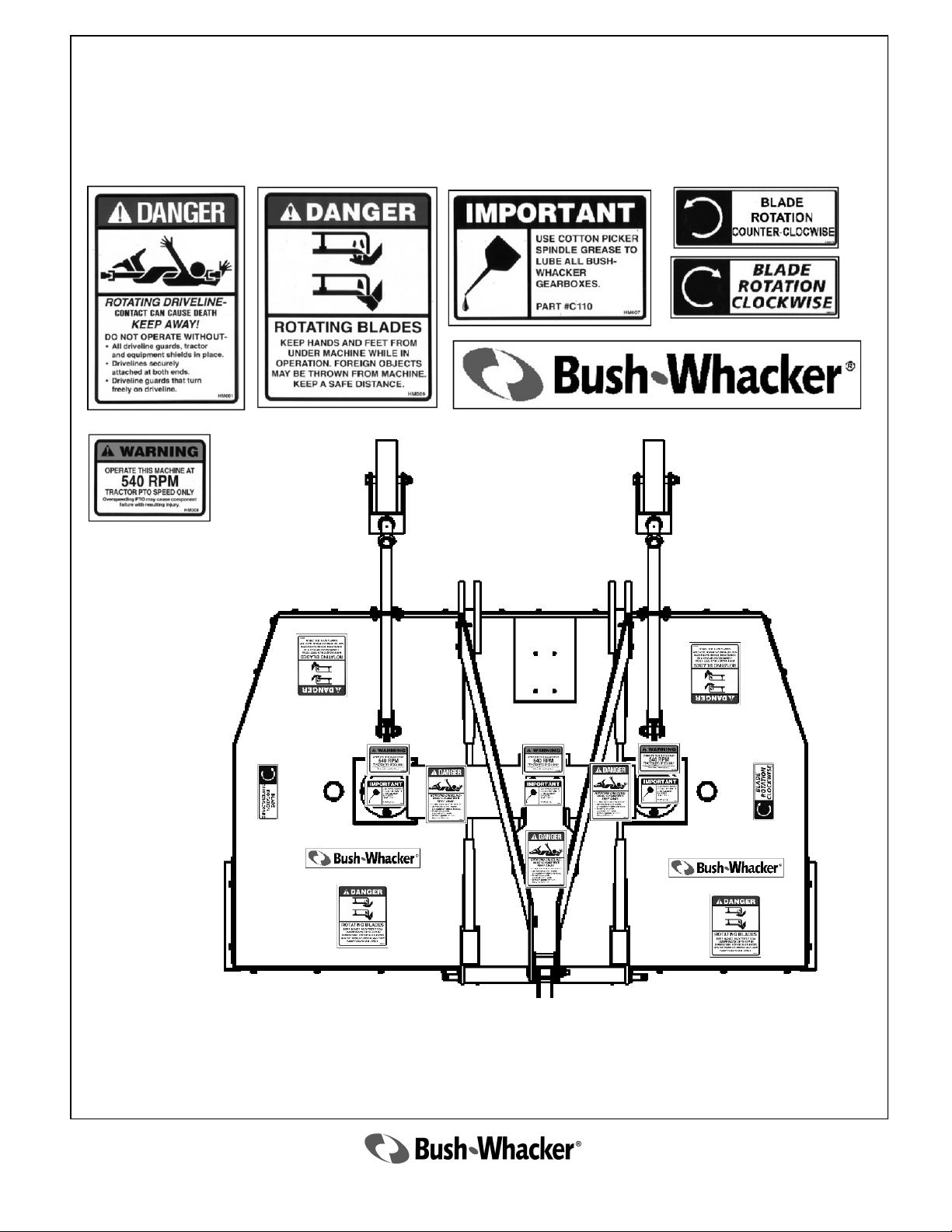
Decals Part Numbers and Placement
2569 2572 4416
4415
540 Rpm - 4169
1000 Rpm - 4170
CW - 4167
CCW - 4168
6
2010 ST-104
Page 7
Safety Warnings
Operations
This mower operates at a PTO speed of 540 RPM only. Check the tractor manufacture’s
instruction manual for the proper engine RPM to achieve the proper PTO speed. DO NOT
operate the mower at any higher RPM, doing so will cause damage to the mower as well
as create an extreme hazard to the operator, passersby, or animals. Also note that doing so
will void the warranty of the machine.
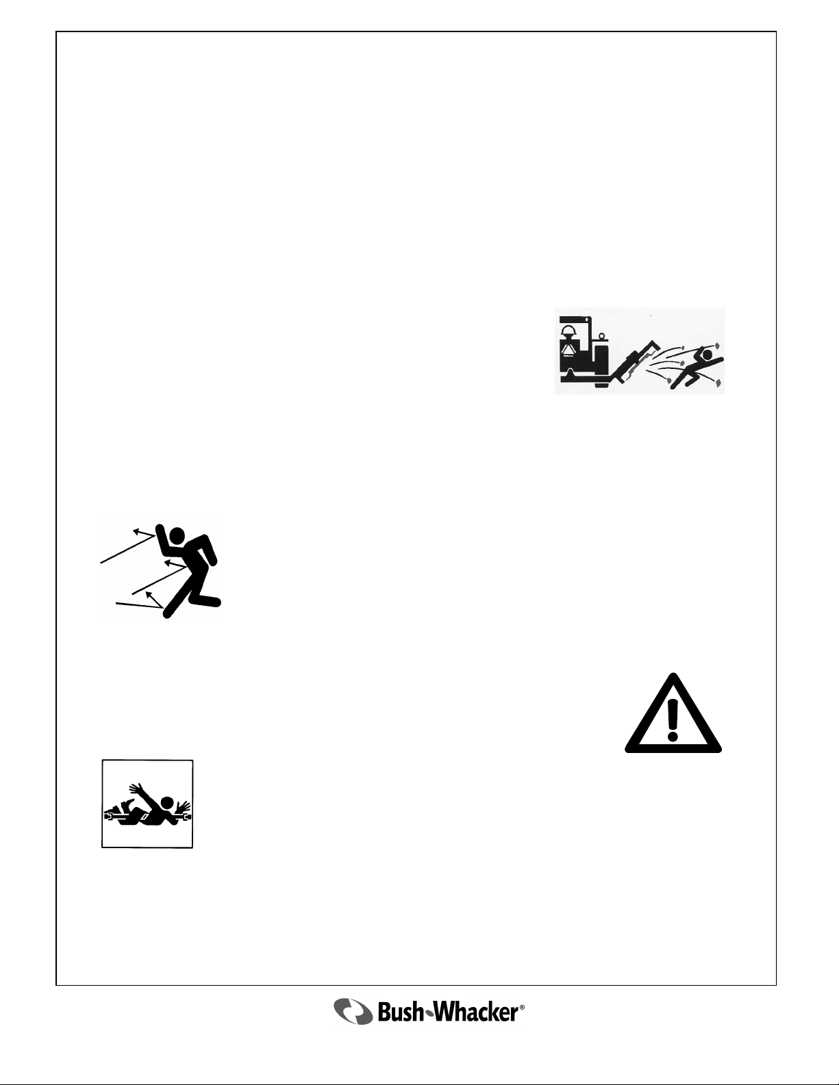
NEVER operate a rotary mower with a person or animal in the
area. The blades may throw objects for great distances and can
strike a person, passersby, or animal causing serious injury or
death.
Stop operation of the machine for a passerby or if someone appears to be approaching the area.
Objects can be thrown for hundreds of yards at great speed.
ALWAYS inspect the deflector shields and/or chain guards daily to ensure
that they are in proper working order and that no chains are missing. If the
deflector shields or chain guards are not operating correctly, chain links are
missing, or the complete deflector shields or chain guards assembly is
missing, do not operate the mower. NEVER OPERATE THE MOWER
WITHOUT CHAIN GUARDS OR DEFLECTORS IN PROPER
WORKING ORDER.
Rocks, gravel, wire, rope, bricks, or similar objects are potential hazards for
rotary mowers operation. These items can cause damage to the machine; but
more importantly, they can be ejected from underneath the mower at very high
speeds, resulting in property damage, injury or even death. Always inspect the
mowing area prior to the operation of any rotary mower. If any of these objects
or similar objects are found, remove them immediately before operation.
NEVER operate the mower without the driveline safety shields in place and in
proper working order. Operation without safety shields can lead to injury or
death.
EXTREMELY IMPORTANT—Make sure all gearbox shields are in place and tightened before operating the mower. If one works loose, stop mowing and tighten immediately. NEVER
OPERATE THE MOWER WITHOUT ALL GEARBOX SHIELDS PROPERLY INSTALLED. OPERATION WITHOUT SAFETY SHIELDS MAY CAUSE SERIOUS INJURY OR DEATH.
2010 ST-104
7
Page 8
Safety Warnings
Operations
Avoid hitting hard solid objects such as large rocks, concrete culverts, guard
rails, etc. This could cause serious damage to the machine. Broken machine
parts or pieces of the object can be thrown at very high speeds. This could result in serious injury or death to persons at a considerable distance from the
rotary mower.
NEVER ALLOW ANYONE TO RIDE ON THE MOWER OR
THE TRACTOR. This equipment, if not operated properly, could be
potentially dangerous; therefore, NEVER ALLOW A CHILD TO
OPERATE A ROTARY MOWER.
Thoroughly examine the rotary mower each day before operating. Tighten
loose bolts, nuts, and hydraulic fittings. Replace all damaged or broken parts,
including hydraulic hoses. If rotary mowers are not kept in proper working
order, they could be damaged and this could result in serious injury.
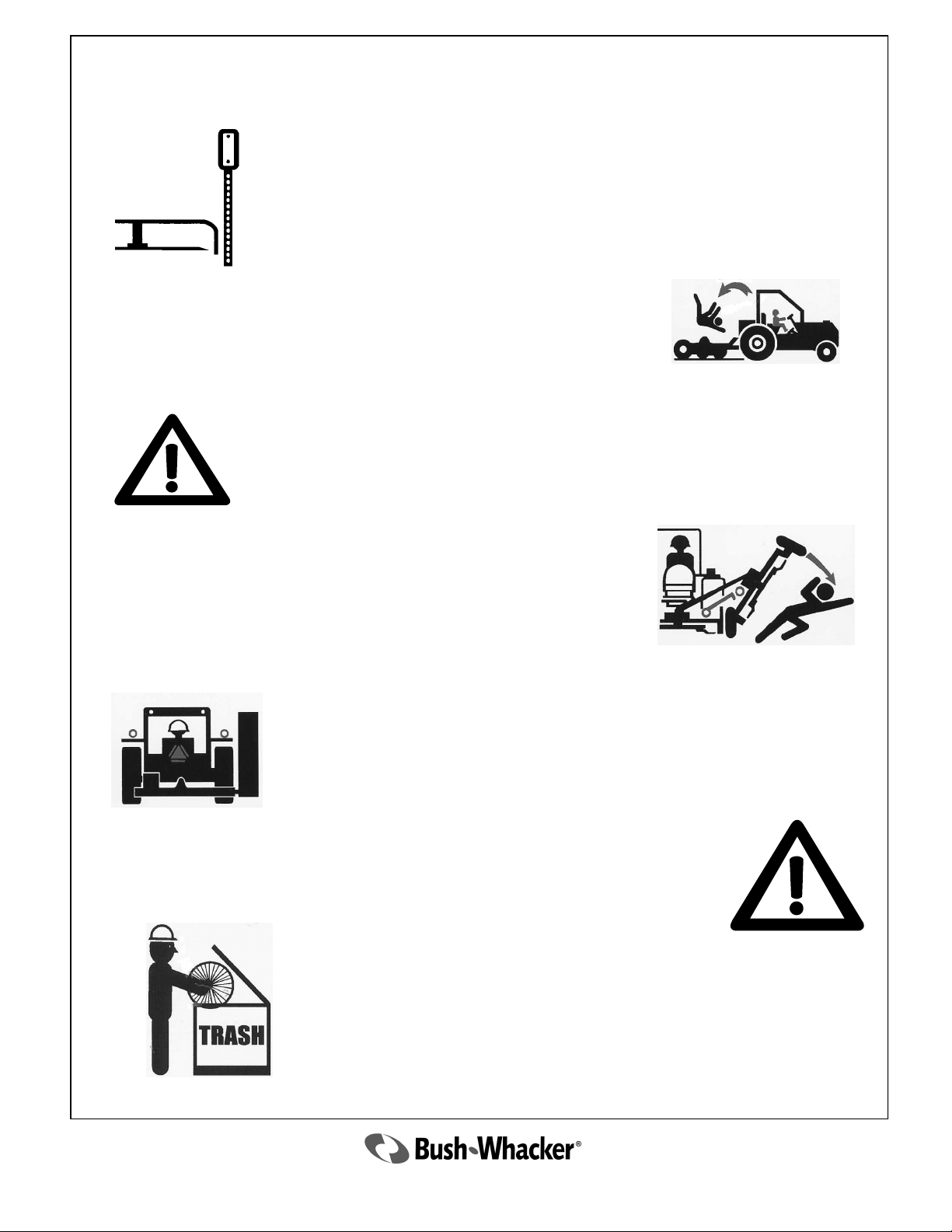
NEVER engage in repair work under the mower deck or any other
part of the mower that is raised off the ground until the mower is
safely and securely supported in the raised position. Inadequate
support can result in the mower falling, which could result in serious injury or death.
Use proper signage around working area. This will help the operator
have a safe place to work, and help passers by to take appropriate
precautions.
Use the proper reflective devices on the equipment to help prevent
accidents.
Make sure that all rules of the road are followed, and Slow Moving
Vehicle (SMV) rules are also observed
Always inspect the area before mowing for potential mower hazards.
Remove or avoid all foreign objects such as wire, cable, metal objects, and
all other foreign material. Failure to do so could result in serious injury
to the operator or passerby from foreign material being thrown from
the mower.
8
2010 ST-104
Page 9
Safety Warnings
Attaching/Detaching Cutter
If operating along roadway, keep equipment within the lane closest to the
work area. Never operate equipment against the flow of traffic, which
could possibly result in a head-on collision causing serious injury or death.
Never use equipment around railroad tracks without direct railway supervision.
Inexperience in railway operations may cause loss of communications, loss of
signals, rail and tie damage or derailment.
NEVER railway tracks anywhere other than at normal traffic crossings.
Unauthorized machinery on railways are in extreme danger of being struck by
locomotives and railway machinery resulting in damaged equipment, serious
injury or death.
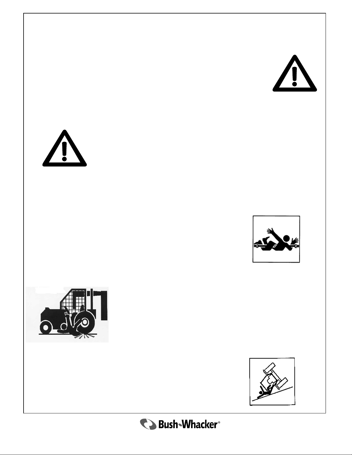
Before approaching any rotary mower or before dismounting the tractor,
always make sure of the following:
The tractor transmission is in the parking gear, and the parking brake is set
to keep the tractor from moving while unattended.
The tractor PTO is disengaged.
The engine has stopped, the key is out of the ignition, and all moving parts
(both tractor and mower) have completely stopped. The rotating parts of
the tractor and rotary may mower continue to rotate after the PTO has been
disengaged. THE OPERATOR SHOULD REMAIN SEATED UNTIL
ALL MOVEMENT HAS CEASED!
NEVER WORK ON THE ROTARY MOWER WITH
THE POWER ON.
Rollover
Care must be taken when operating on uneven terrain, ditches, or embankments. The chances of the tractor and/or mower rolling over are increased.
Also, the chance of objects being thrown by the blade are increased when
operating under these adverse conditions.
2010 ST-104
9
Page 10
Safety Warnings
Rollover
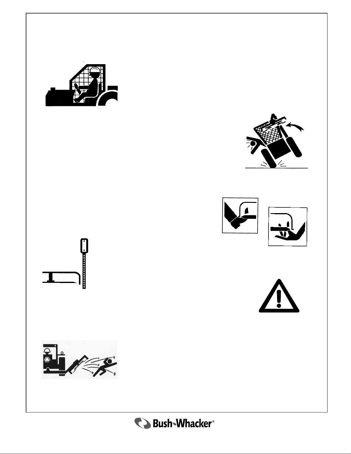
Never operate the equipment without the Roll-Over Protective
Structure (ROPS) and without a seat belt. These items prevent
injury in a roll-over accident. It is also highly recommended to
wear protective equipment such as a hard hat, safety glasses,
safety shoes, and ear plugs.
OPERATE CAREFULLY! It is important to slow down when
turning and when going down slopes. Doing so could result in a roll
over and injury, or possibly death, to the operator.
Rotating Blades
Stay away from rotating blades. Keep hands and feet clear
of rotating blades and discharge areas at all times. Never
get close to the blades until all motion has stopped and machine is turned off.
Never allow rotating blades to contact solid objects like rocks, posts, curbs
or guard rails. Only operate if all guards and deflectors are in place and
in good working condition.
Never operate equipment with loose blades. Retighten after the first 8
hours of use and after blade replacement.
Never operate with Cutting Head raised if bystanders or
traffic are in the area to prevent injury or death from objects
thrown by Blades.
Stop cutting if someone comes within 300 feet. DO NOT
operate equipment with bystanders in the area! Rotary
mowers have the ability to throw debris considerable
distances when blades are allowed to strike foreign objects.
Operator must exercise caution or serious injury or even
death could result.
10
2010 ST-104
Page 11
Safety Warnings
Hydraulics
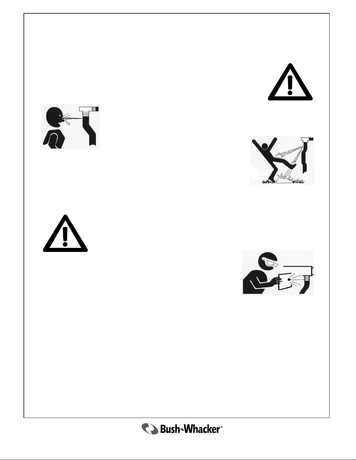
Relieve all pressure in the hydraulic lines by setting the mower deck on the
ground, shutting the tractor off, and actuating lift valve handles before disconnecting hoses. This relief of pressure will reduce possibility of serious
injury from spewing hydraulic fluid.
Frayed, torn, or crimped hoses may rupture and spray boiling oil onto
Operator and cause serious bodily injury from scalding.
Failure to inspect and repair or replace hoses may cause worn hoses
to rupture suddenly and violently resulting in serious bodily injury
from scalding or fire with resulting burn injury or death.
Boiling oil may spray onto hot tractor parts and catch fire causing severe burn injury or death.
Inspect hoses daily and repair or replace when needed. Stop all leaks.
Repair or replace hoses as indicated to prevent unexpected failure and
possible serious injury to operator or bystander.
Use paper or cardboard to check for leaks. Never use your hand.
If oil penetrates skin, gangrene or other serious injury could occur.
If skin is penetrated by hydraulic fluid, get immediate medical
attention.
Safety Conclusion
Now that the operator has read the information provided in this manual; he or she should now
be aware of how dangerous a rotary mower can be if operated improperly. It is important that
the operator of this equipment should be cautious, conscientious, and use common sense when
operating this equipment in order to avoid serious injury and or death to the operator, support
personnel, passersby, or animals.
Safety
Depends on You!
2010 ST-104
11
Page 12

General
Maintenance
Tips
12
2010 ST-104
Page 13
General Maintenance
Refer to tractor’s service manual for proper tractor maintenance.
NEVER service the mower with the power on, except where otherwise stated.
Before working on a mower always check to see that:
The tractor’s transmission is in the parking gear and the parking brake is set to keep the
tractor from moving while unattended.
The tractor PTO has been disengaged.
The engine is off and all moving parts (both tractor and mower) have completely stopped.
The rotating parts of the tractor and mower continue to rotate after the PTO has been
disengaged. The operator should remain seated until all movement has ceased.
Never engage in repair or service work under the mower deck or any other part of the mower
that is raised off of the ground until the mower is safely and securely supported in the raised
position.
Use extreme caution when working on a mower. Many of the parts are heavy and sharp and
can cause serious injury if they are dropped or fall on the operator or bystander.
The blades are very sharp and can pivot. Use extreme caution when performing maintenance
on them. Failure to do so could result in serious injury or possibly even death.
Use marfac double ought grease or 0 weight cotton picker spindle grease to lubricate all BushWhacker gearboxes. Replacement gearbox grease is available from your Bush-Whacker
dealership.
Always use genuine Bush-Whacker replacement parts, available through the network of
authorized dealers. The use of non-OEM parts will void the warranty of this machine.
Non-OEM parts may not meet Hall Manufacturing Inc. specifications and could lead to
serious injury or death.
At Least Twice Daily
Rotor Bar Assembly, Blades, Blade Bolts, and Nuts
Check blades for any signs of cracking or damaged cutting surfaces. If a blade is cracked,
replace the set at once. DO NOT operate the mower at any time with a cracked or severely
damaged blade! If a blade breaks, it could cause severe injury or possibly death.
Check if blade cutting surfaces are dull. If they are, re-sharpen or replace blades.
Check if blade bolts and nuts are loose, cracked or damaged. DO NOT operate the mower
with any of those characteristics. Any of these conditions could allow the blade to come
loose and could cause injury or possibly death. Always keep the blade bolts and nuts
tightened to 350 ft. lbs. of torque.
DO NOT operate the mower with just one blade.
2010 ST-104
13
Page 14
At Least Twice Daily
Rotor Bar Assembly, Blades, Blade Bolts, and Nuts
Make sure rotor bar assembly is securely attached with castle nut and cotter pin to the
output shaft.
Always make sure to replace the blades in sets.
NOTE: When mowing at low cutting heights or on uneven terrain, the blades can come in
contact with the ground frequently. When this happens, the blade tips can be pushed upwards
causing the blade to bend. By pushing upwards on the blade tip, the rear of the blade (at the
bolt hole) is forced downward away from the rotor bar assembly. This causes the bolt to be
pulled through the bar and can cause it to shear. When the bolt shears, it will throw a blade.
When operating in these conditions, the operator must check the blade bolts more frequently
than normal, at least four times a day.
Always use genuine Bush-Whacker replacement blades, bolts, and nuts. Other blades may not
meet Hall Manufacturing specifications and could lead to serious injury or death.
Hydraulics
If at any time the hoses become frayed, worn, or pinched, replace them.
Daily
Shields
Make sure ALL shields are in place and tightened before operating the mower. If one
works loose, stop mowing and tighten immediately.
Replace shields if there’s any damage or excessive wear.
Drive Shafts
Inspect the Drive Shaft Shields, make sure that they are installed and working properly. If
shields become damaged or loose during operation, stop immediately and fix or replace
them.
Make sure the drive shaft shield mounting chains are securely fastened.
Inspect cross kits
Grease each zerk fitting with natural or synthetic lubricants. Never mix the two types of
lubricants.
Check Drive Shaft tubes to ensure that they telescope properly. If they do not, replace
them.
14
2010 ST-104
Page 15
Daily
Gearboxes
Check gear lube. If the grease is lower than the inspection plug on the rear side of the
gearbox, then fill to the level of the plug. NOTE: Do not overfill the gearbox. If the grease
level of the gearbox is low, additional grease can be purchased from your Bush-Whacker
dealer.
Inspect output shaft for vines, wire, rope, etc. that may collect around the shaft and tear up
the output seal. If a seal is leaking, replace it, or risk overheating and severe damage to the
equipment.
Check the mounting bolts and nuts to be sure that they are correctly secured. If left
unchecked, it could cause excessive vibrating which could damage the equipment.
Pins, Bolts, and Nuts
Inspect all pins, bolts, and nuts, making sure that they are all in place and secure. Look for
loose fasteners and tighten to the proper torque as required.
Make sure the three point hitch mount and stabilizer pins are secure, and top links are not
loose or slack.
Skid Shoes
Check for any wear or damage, replace if required.
Frame
Look for any structural cracks, damage and wear.
Keep the equipment clean. Inspect for debris caught in the machine, especially at all pinch
points.
Wheel Hubs
Grease wheel hubs at zerk fitting once a day before operating the mower. Check seals for
leakage. Replace seals if a leak is detected. Also, check bearings for damage. If they have
seized, they are damaged; replace them immediately before use.
Chain Guards
Rear and front chain guards and front metal deflectors are standard equipment for all Bush-
Whacker rotary mowers.
Always inspect the chain guards and deflectors to be sure no chain links are missing and the
guards are operating correctly. If the guards are not operating correctly, links are missing, or
the complete chain guard assembly is missing, do not operate the mower. Never operate
the mower without chain guards in proper working order.
Every 1,000 Hours or Annually
It is recommended to do annual, pre-season maintenance at the end of each operating season,
rather than at the beginning.
The mower should be stored in the off-season cleaned, inspected and repaired. This will
prevent any rust forming on the mower’s surfaces and contaminants damaging the hydraulic
components.
2010 ST-104
15
Page 16

1. Drain all gear oil from the gearbox by removing the drain plug located on the gearbox housing below the gearbox mounting flange.
2. Remove the 8 inspection cover bolts from the top of the gearbox. Remove the inspection
cover to expose the input shaft.
3. Remove the bolts from blank cap. Remove the blank cap taking care not to damage the gasket between the cap and housing.
4. Remove the retaining ring between the shaft and gear (for gearboxes with gears on the back
side of the input shaft only).
5. Press out input shaft through blank cap hole. This will remove the race and allow the shaft
to slide out. Gear may be removed through the top of the gearbox housing. Seal, retaining
ring, and race may be removed from the front of the gearbox if necessary. It is very important to make note of the location of the shims used when removing the input shaft.
6. Remove the cotter pin and retaining nut from the output shaft. The output gear will slide off
of the output shaft. Remove any shims that may be present.
Gearbox Disassembly Procedure
7. Remove seal protector from output of gearbox housing and remove the retaining ring underneath.
8. The output shaft assembly will have to be pressed out from the inside or it can be pulled out
through the bottom of the housing. The output seal, spacer, and lower bearing will be removed with the shaft. The upper bearing will be pressed off the end of the shaft.
9. If any of the bearing races in the housing need to be removed, a blind hole bearing puller
should be used.
10. See page 20-21 for parts breakdown.
16
2010 ST-104
Page 17

1. The output assembly goes into the housing first. If the upper bearing race has been pulled
out it must be pressed in. The lower bearing must be pressed onto the shaft before installation.
2. Once the output shaft is in place, install the upper bearing, shims, gear, and retaining nut.
3. The bearing preload is measured by rolling torque. The rolling torque should be between 615 inch pounds. Adjust the retaining nut until you reach this rolling torque. Secure the retaining nut with the cotter pin.
4. The bearing race for the front bearing on the input shaft must be pressed in. Outer retaining
ring should be installed in the gearbox housing. Make sure the shims are installed between
the retaining ring and race as necessary.
5. Place the input shaft through the back of the gearbox while holding the gear in place. Slide
the shaft through the gear and press into the front bearing. Ensure the shaft to bearing retaining ring is installed on the front of the input shaft. Install the gear to shaft retaining ring.
6. Press bearing onto the back of the shaft. Be sure to replace any shims that were removed
during disassembly. Press race partway into the back of the gearbox housing. Install the cap
on the back of the housing using the appropriate gasket and tighten the bolts to 38 ft-lb.
7. Check contact pattern of gear set with marking compound. Contact is to be in the central
toe area of the gear teeth with a minimum 50% tooth height and 50% tooth length in contact. The back lash should be between 0.006‖ and 0.022‖ when measured at the pitch diameter of the gear set. If the gear mesh or back lash are incorrect use shims reposition the gears.
8. The bearing preload is measured in the same manner as for the output shaft. The rolling
torque should be between 11-25 inch pounds. Install thicker gaskets to decrease the rolling
torque and thinner gaskets to reduce the rolling torque.
9. Once the preload is set, install the output spacer, seal, retaining ring, and seal protector. Install the input seal in the housing. Remove the blank cap and apply sealant to the gaskets
and replace the cap. Torque the bolts back to 38 ft-lb.
10. Replace the inspection cover on the top of the gearbox and torque the bolts to 20 ft-lbs.
11. Fill the gear box with the recommended lubricant in an upright position similar to the
mounting position. Fill the gearbox to the level plug.
Gearbox Assembly Procedure
2010 ST-104
17
Page 18
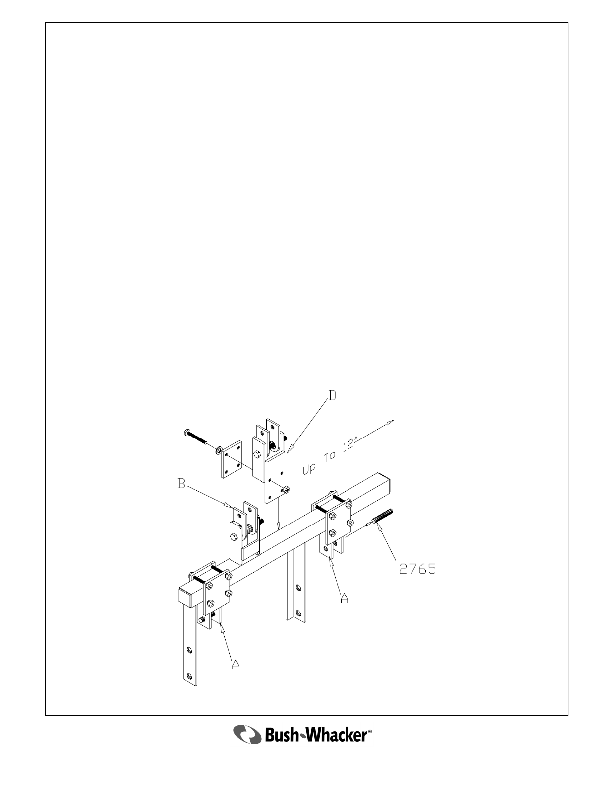
Using The Optional Offset Adapter
I. Mowing in the Center Position
1. Attach the tractor lift arms to the mower and adapter at points ―A‖ using the hitch pins,
Part# 2765, provided.
2. Attach the tractor top link to the clevis and adapter at point ―B‖.
3. Hook to the offset adapter is now complete.
II. Mowing in the Offset Position
Note: Always adjust the offset adapter with the mower disengaged from the tractor and
firmly on the ground. This will prevent the machine from becoming unstable and falling
onto the operator. Failure to do so might cause serious injury or death to the operator.
1. Attach Part D leaving the fasteners slightly loose. (Note: Part D also includes the top link
clevis)
2. Loosen Part A and slide Part A&D to the desired offset Position (up to 12‖) and tighten
them securely into place.
3. Attach the mower to the tractor as stated in Part I except now the operator must attach the
top link to Part D.
18
2010 ST-104
Page 19

Parts book
2010 ST-104
19
Page 20
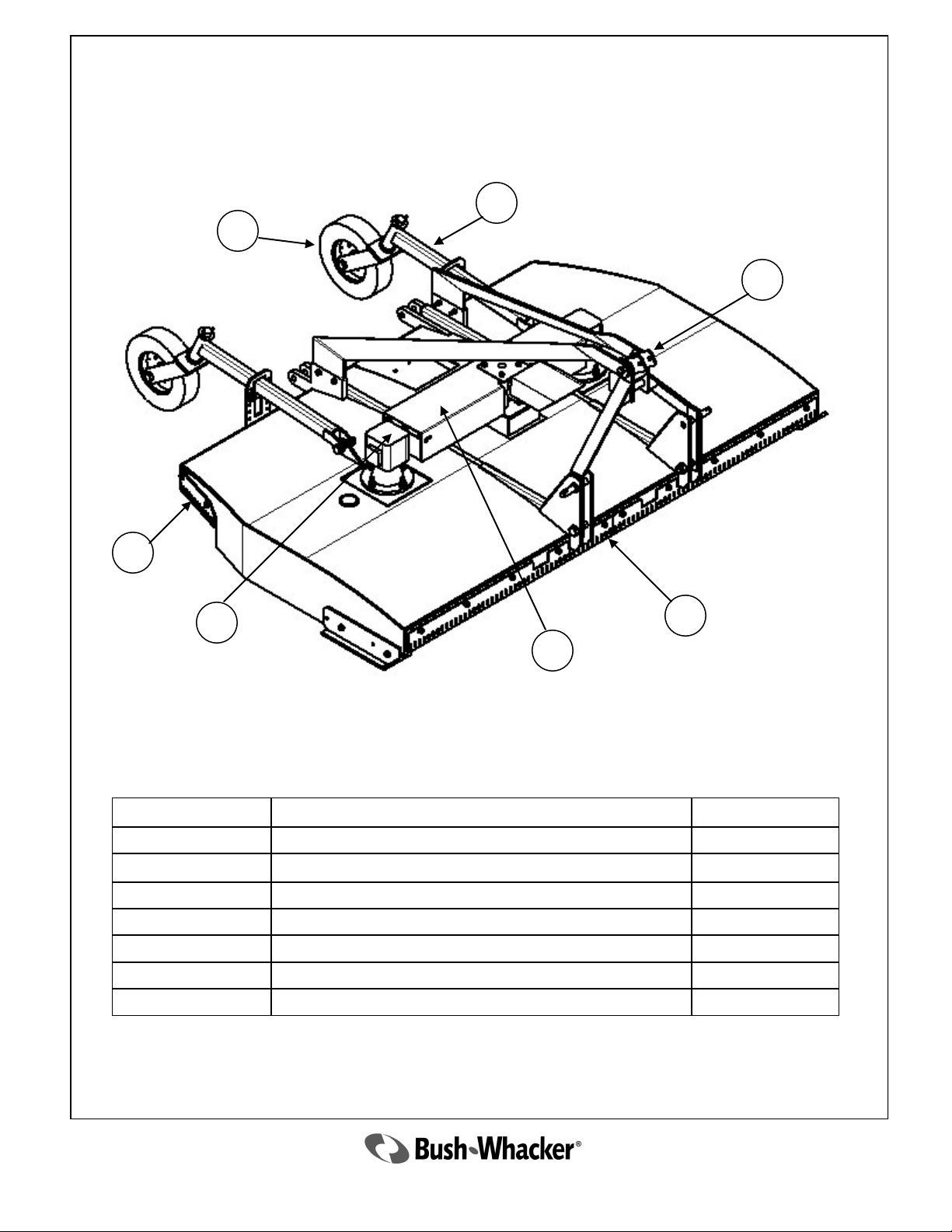
ST-104 Lift Type
Assembly Breakdown
3
4
2
7
6
5
Ref. No. Description Page Number
1 Front Chain Guard 34-35
2 Hitch Frame Assembly 21
3 Tail Wheel Axle Assembly 30
4 Tail Wheel Fork & Wheel Assembly 31
5 Gear Box Shields 32
6 Gearbox 22-26
7 Rear Chain Guard 34-35
1
20
2010 ST-104
Page 21
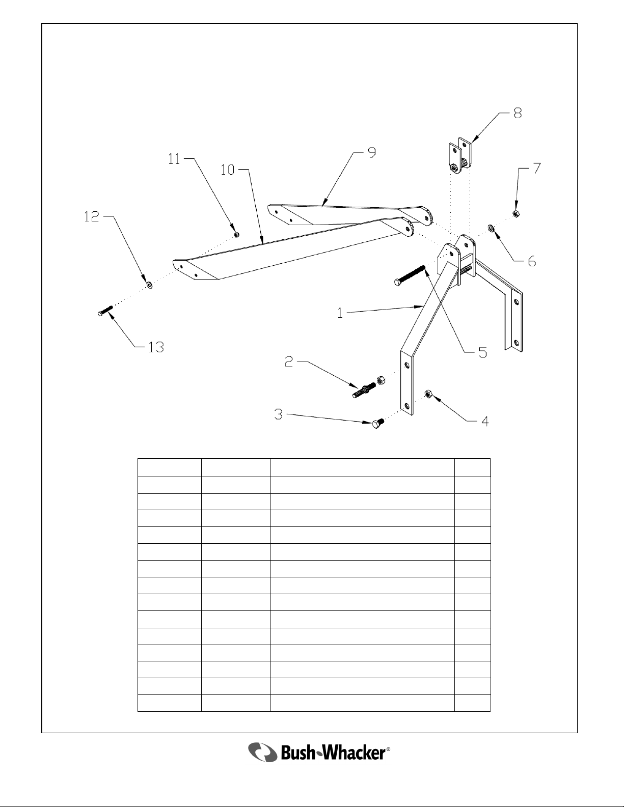
Hitch Frame Assembly
Ref. No. Part No. Description Qty
1 4379 Hitch Frame 1
2 C222 Hitch Pin 2
3 3373 Bolt 2
4 3374 Nut 2
5 3284 Bolt 1
6 3285 Washer 1
7 2077 Nut 1
8 3287 Category I Clevis 1
4860 Category II Clevis 1
9 5633 Left Brace 1
10 5634 Right Brace 1
11 2336 Nut 4
12 2337 Washer 4
13 3659 Bolt 4
21
2010 ST-104
Page 22
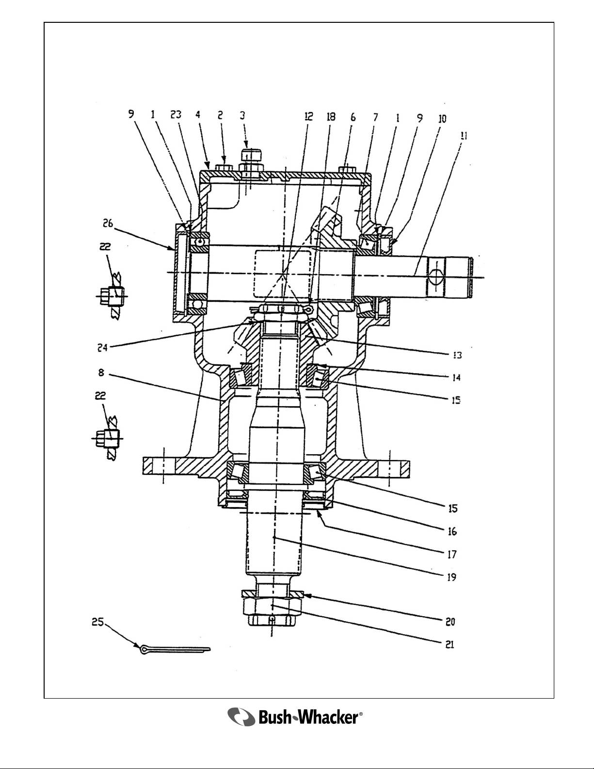
3869 Gear Box
22
2010 ST-104
Page 23
3869 Gear Box (USE “0” WEIGHT OIL ONLY)
Ref. No. Part No. Description Qty
1 3861 Shim 2
2 2683 Bolt 4
3 1623 Vent Plug 1
4 3862 Cover 1
6 3206 Gear 1
7 3863 Bearing 1
8 3864 Housing 1
9 2036 Snap Ring 1
10 2037 Seal 2
11 3865 Input Shaft 1
12 1609 Nut 1
13 3205 Gear 1
14 1610 Shim 1
15 1615 Bearing 1
16 1614 Seal 2
17 1613 Seal Protector 1
18 2690 Cotter Pin 1
19 3866 Output Shaft 1
20 1611 Washer 1
21 1612 Nut 1
22 3867 Pipe Plug 2
23 3868 Bearing 1
24 1625 Shim 1
25 1626 Cotter Pin 1
26 4144 Cover 1
2010 ST-104
23
Page 24
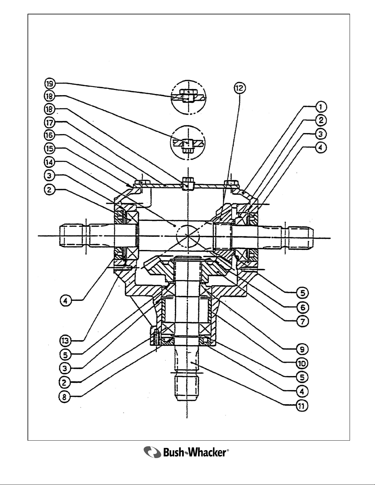
2033 Transfer Gear Box
(USE NUMBER “0” WEIGHT OIL ONLY)
24
2010 ST-104
Page 25
2033 Transfer Gear Box
(USE NUMBER “0” WEIGHT OIL ONLY)
Ref. No. Part No. Description Qty
1 2034 Housing 1
2 2035 Bearing 3
3 2036 Snap Ring 3
4 2037 Seal 3
5 2038 Shim AR
6 2039 External Circlip 1
7 2040 Gear 1
8 2041 External Circlip 1
9 2042 Bearing 1
10 2043 Spacer 1
11 2044 Input Shaft 1
12 2045 Pinion 1
13 2046 Shim AR
14 2047 Output Shaft 1
16 2048 Hex Bolt 4
17 2049 Cover 1
18 2050 Plug 1
19 2051 Oil Filler Plug 1
2010 ST-104
25
Page 26
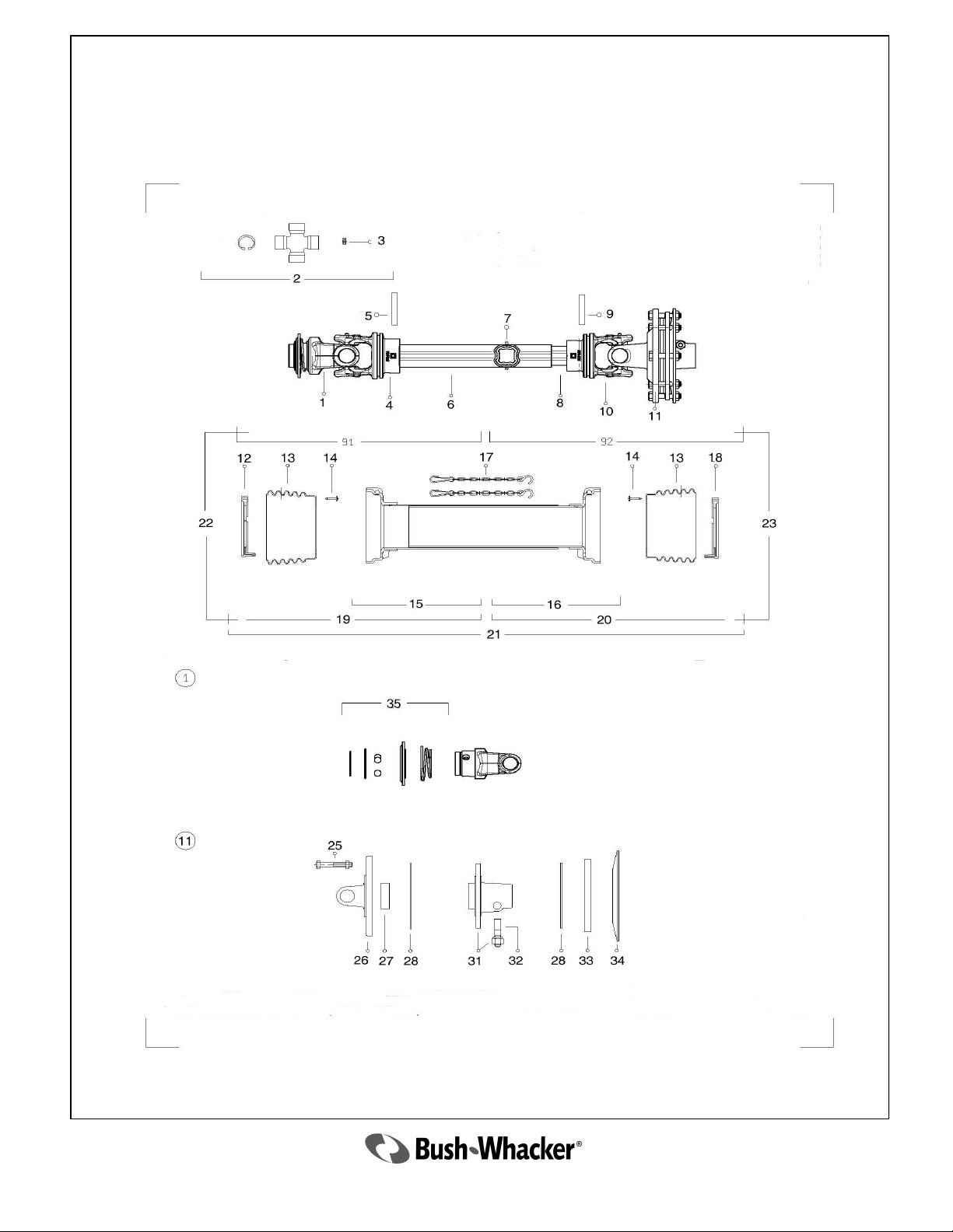
4050 Main Drive Shaft for Lift Type
26
2010 ST-104
Page 27
4050 Main Drive Shaft for Lift Type
Parts List
Ref. No. Part No. Description Qty
1 5071 Yoke 1
2 4902 Cross Kit 2
3 4939 Grease Fitting 1
4 3942 Outer Tube Yoke 1
5 3919 Outer Roll Pin 1
6 4039 Outer Tube (Steel) 1
7 4008 Grease Fitting 1
8 4040 Inner Tube (Steel) 1
9 3922 Inner Roll Pin 1
10 3945 Inner Tube Yoke 1
11 4041 Complete Clutch Assembly 1
12 3927 Outer Shield Ring 1
13 3947 Shield Bell 2
14 3928 Shield Screw 6
15 4042 Outer Shield Tube 1
16 4043 Inner Shield Tube 1
17 4012 Shield Safety Chain 2
18 3932 Inner Shield Ring 1
19 4044 Outer Shield Complete 1
20 4045 Inner Shield Complete 1
21 4046 Complete Shield Assembly 1
22 4047 Outer Half Shaft Complete 1
23 4048 Inner Half Shaft Complete 1
25 5075 Bolt with Nut 8
26 4018 Flange Yoke 1
27 3962 Bushing 1
28 5072 Clutch Disk 2
31 4049 Splined Hub 1
32 5054 Pin with Nut 1
33 3968 Outer Plate 1
34 5073 Spring 1
35 5074 Spann Kit 1
2010 ST-104
27
Page 28
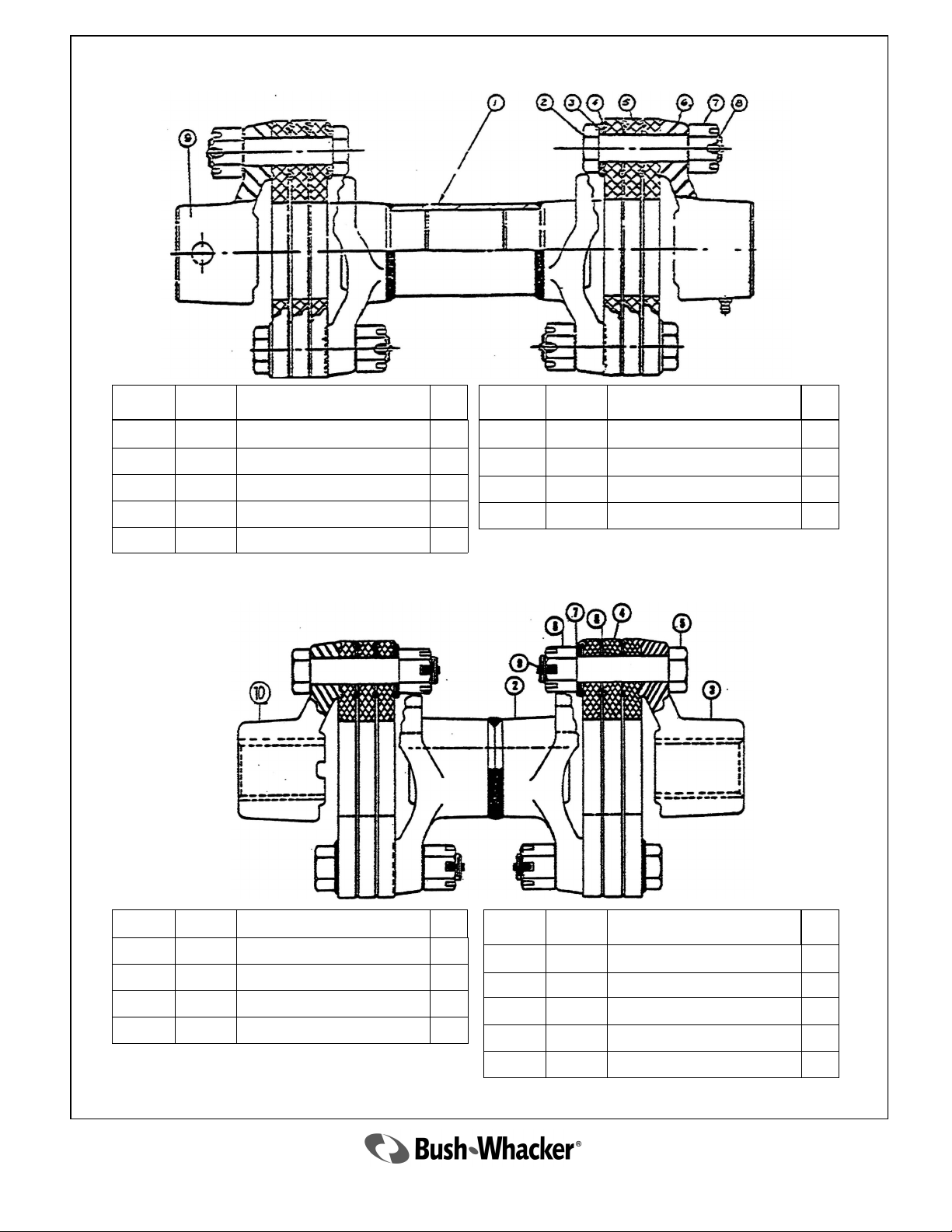
2677 Flexible Coupling
Ref. No. Part No. Description Qty
1 2058A Center Section 1
2 2060 Bolt 12
3 2063 Washer 12
4 2061 Beaded Washer 36
5 2059 Disc 6
2679 Flexible Coupler
Ref. No. Part No. Description Qty
6 2065 Spider 1
7 2062 Nut 12
8 2064 Cotter Pin 12
9 2678 Spider 1
Ref. No. Part No. Description Qty
2 2065A Spider 1
3 2678 Spider 1
4 2059 Disc 6
5 2060 Bolt 12
Ref. No. Part No. Description Qty
6 2062 Hex Nut 12
7 2063 Washer 12
8 2061 Beaded Washer 36
9 2064 Cotter Pin 12
10 2065 Spider 1
28
2010 ST-104
Page 29
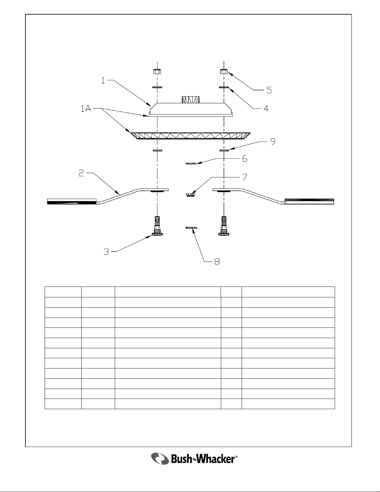
Rotor Bar Assembly
Ref. No. Part No. Description Qty Remarks
1 5631 Blade Bar Only 2 Right and Left
1A 5632 Blade Bar with Stump Jumper REF Right and Left
2 3202 Updraft Blade, CCW 2 Right Side Assembly
Not Shown 3203 Updraft Blade, CW 2 Left Side Assembly
3 3095 Bolt 2
4 2106 Washer 2
5 2105 Nut 2
6 1420 Output Shaft Washer 1
7 1421 Output Shaft Nut 1
8 1422 Cotter Pin 1
9 3096 Washer 2 Only needed when using Stump Jumper
2010 ST-104
29
Page 30
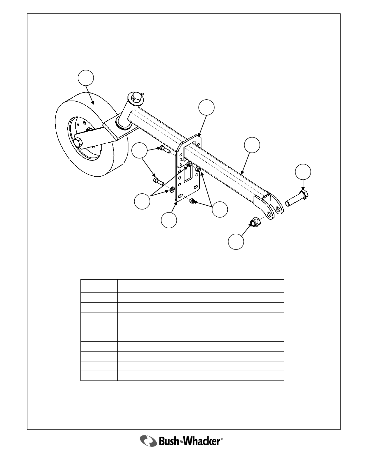
Tail Wheel Tube Assembly
2
4
5
1
7
6
3
9
Ref. No. Part No. Description Qty
1 5624 Tail Wheel Arm 1
2 3176 Tail Wheel Assembly 1
3 5622 Tail Wheel Adjusting Rack Plate 1
4 5623 Tail Wheel Adjusting Rack 1
5 2335 Bolt 4
6 2336 Nut 4
7 2337 Washer 4
8 2303 Bolt 1
9 2105 Nut 1
8
30
2010 ST-104
Page 31
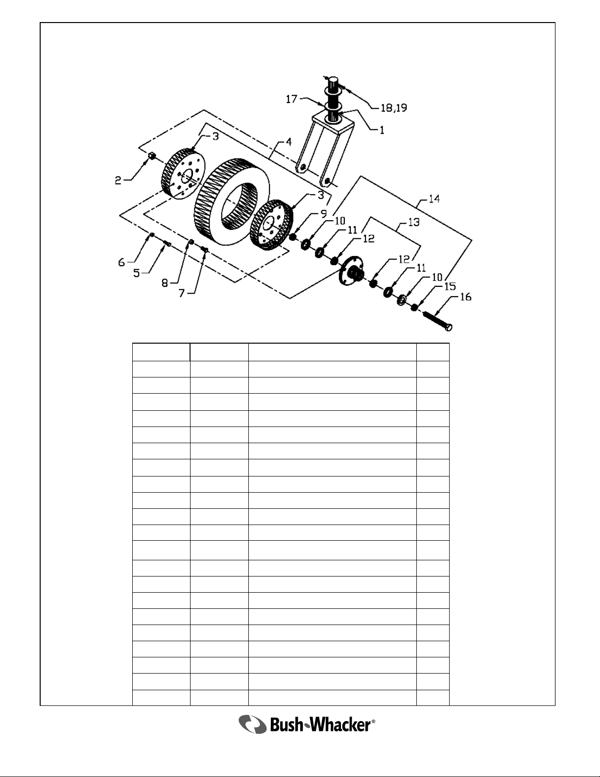
3176 Complete Tail Wheel Assembly
Ref. No. Part No. Description Qty
3176 Complete Tail Wheel Assembly 1
1 3177 Tail Wheel Fork 1
2 2105 Nut 1
3 3179 Wheel Only, 2 piece 1
4 3180 Tire and Wheel—less Hub 1
5 3181 Bolt 5
6 3182 Nut 5
7 3183 Bolt 5
8 3184 Nut 5
9 3185 Spacer 1
10 3186 Seal 2
11 3187 Bearing Cone 2
12 3188 Bearing Cup 2
13 3189 Hub with Races and Studs 1
14 3190 Hub Complete with Bearings and Seals REF
15 3191 Spacer 1
16 3192 Axle Bolt 1
17 3230 Washer 2
18 2513 Nut 1
19 5167 Bolt 1
10,11, 12 4884 Bearing kit 1
31
2010 ST-104
Page 32
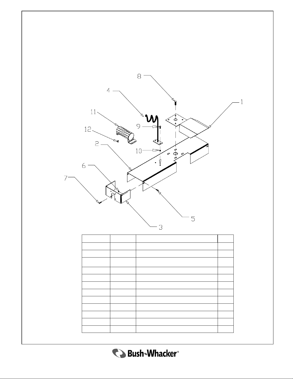
Shield Assembly
Ref. No. Part No. Description Qty
1 2083 Main Drive Line Guard 1
2 3379 Side Drive Line Guard 1
3 4376 Shield Face Plate 1
4 3394 Hose Holder 1
5 2512 Bolt 2
6 2513 Nut 2
7 3006 Bolt 4
8 2053 Bolt 4
9 2512 Bolt 2
10 2513 Nut 2
11 4463 Manual Holder 1
12 4462 Self Tapping Screw 2
32
2010 ST-104
Page 33
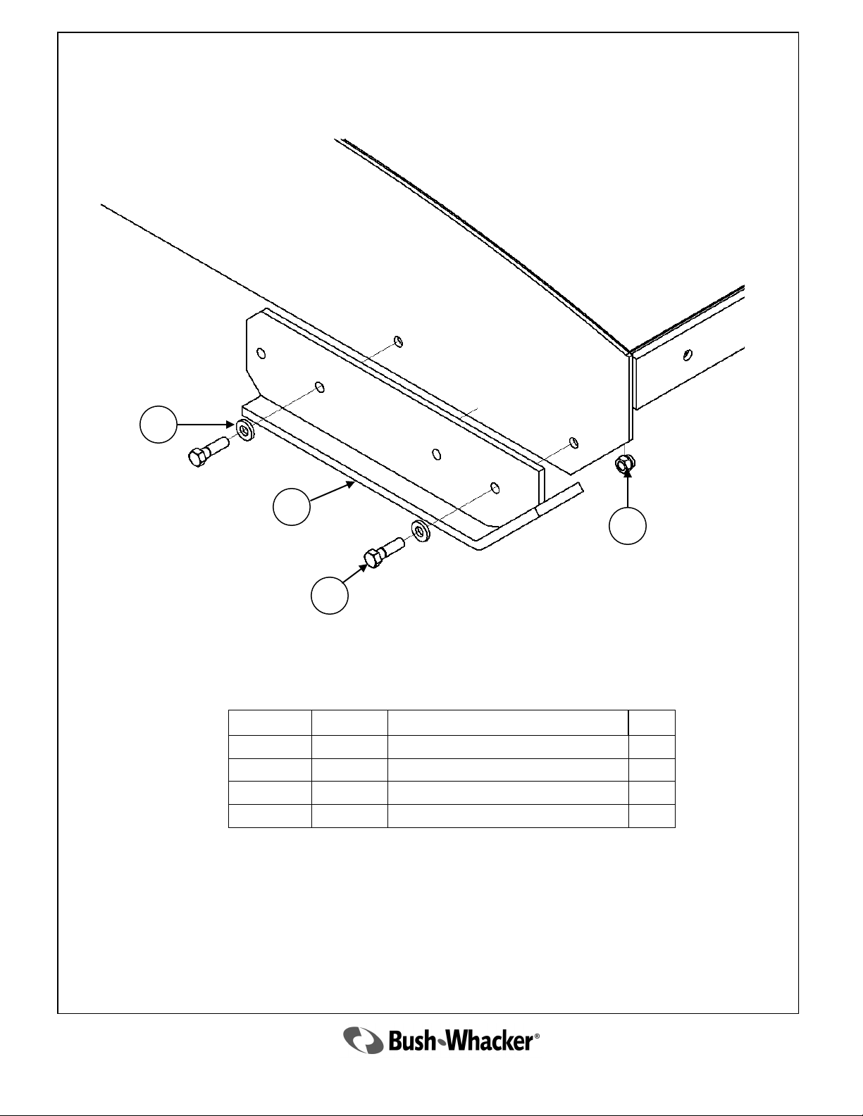
Skid Shoe Assembly
3
1
4
2
Ref. No. Part No. Description Qty
1 5386 Skid Shoe 1
2 2335 Bolt 2
3 2337 Washer 2
4 2336 Nut 2
2010 ST-104
33
Page 34
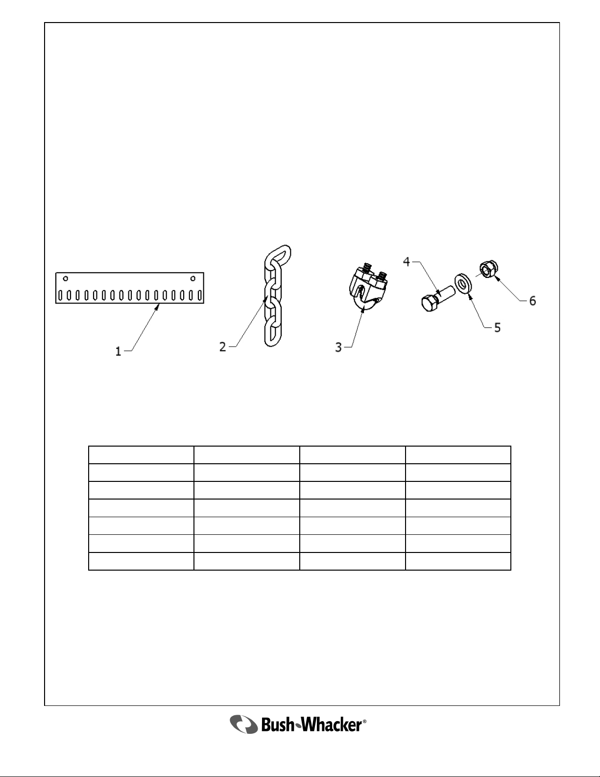
ST-104 CHAIN GUARD HARDWARE
REF # DESCRIPTION PART NUMBER QTY
1 PLATE SEE CHART 1 PER LOCATION
2 CHAIN 3583 VARIES
3 CLAMP 3585 1 PER LOCATION
4 BOLT 2335 VARIES
5 WASHER 2337 VARIES
6 NUT 2336 VARIES
34
2010 ST-104
Page 35
A B
F
E
C
D
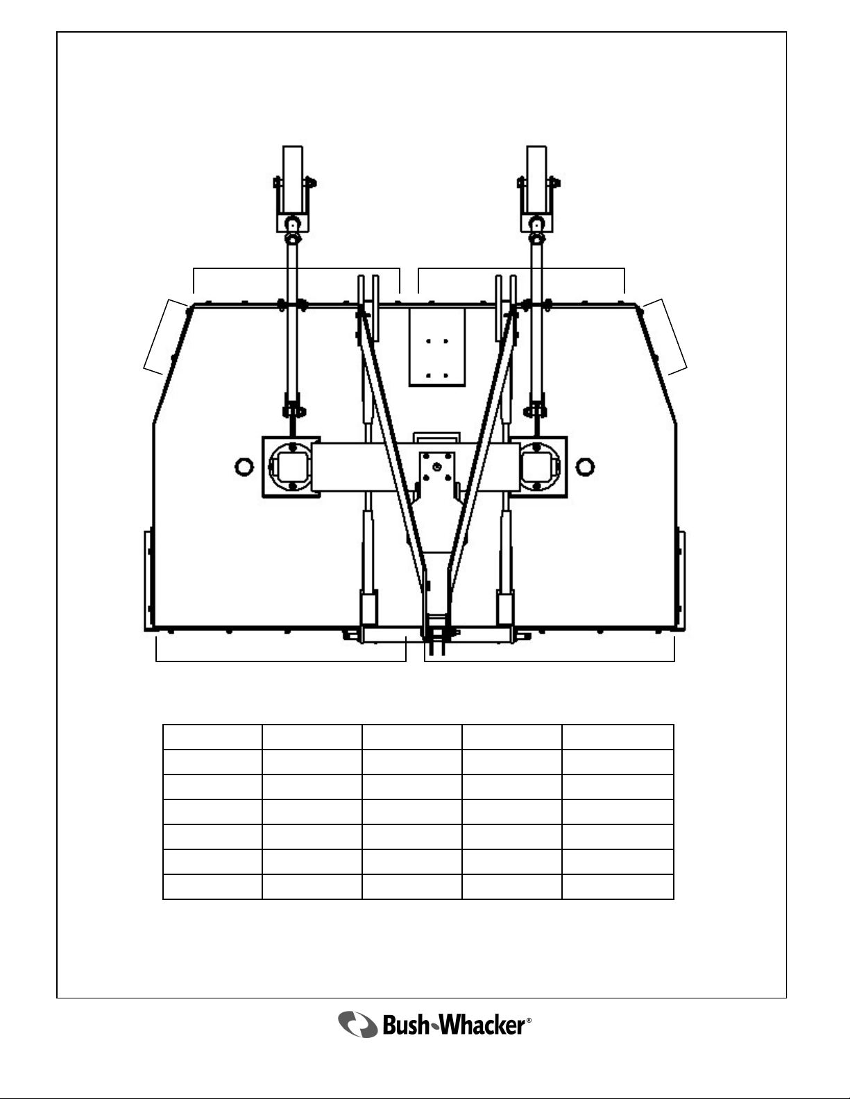
LOCATION ASSEMBLY PLATE CHAIN QTY FASTENER QTY
A 5674 5629 39 6
B 5675 5629 39 6
C 5676 5628 13 2
D 5677 5626 45 5
E 5678 5626 45 5
F 5679 5628 13 2
2010 ST-104
35
Page 36

36
2010 ST-104
Page 37

Optional
Equipment
and
Other Items
not Illustrated
2010 ST-104
37
Page 38
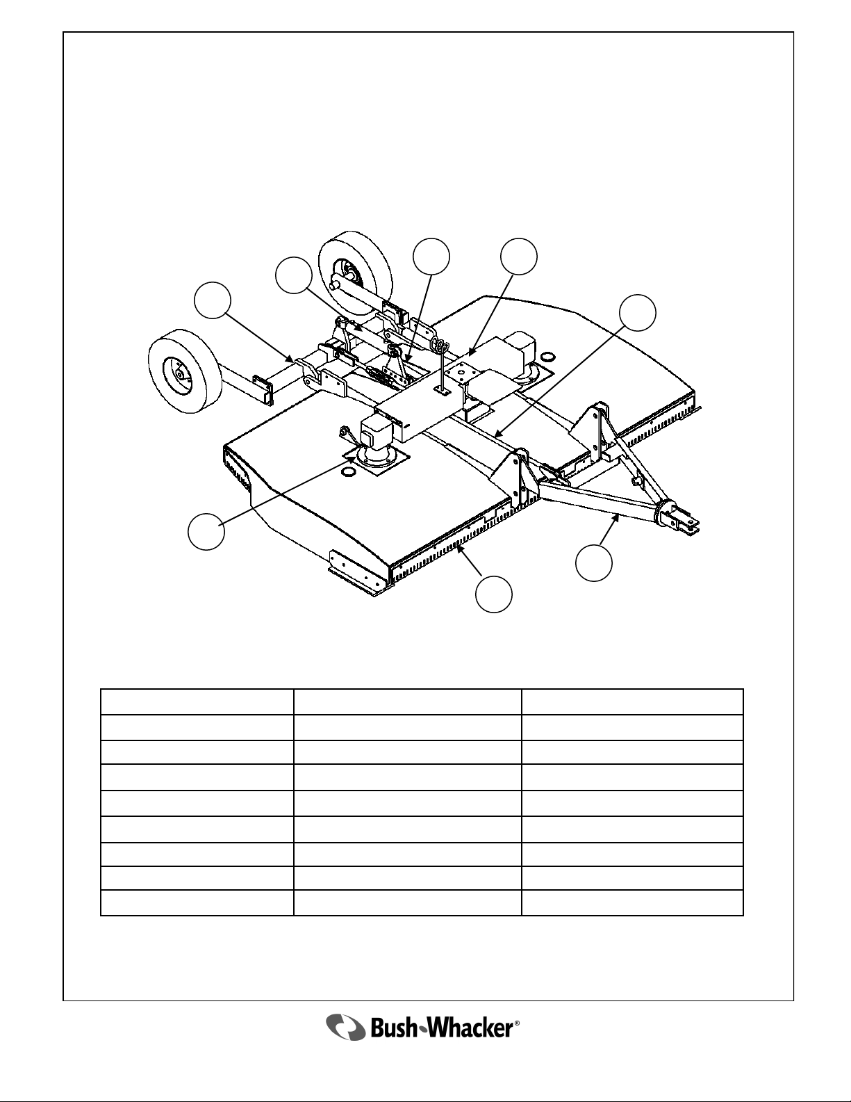
ST-104 Pull Type
Assembly Breakdown
6
7
8
4
5
3
2
1
Ref. No. Description Page Number
1 Chain Guards 34-35
2 Tongue Assembly 39-41
3 Level Rod Assembly 51
4 Gearboxes 22-25
5 Gearbox Shield Assembly 32
6 Cylinder Mount Assembly 49
7 Cylinder 50
8 Pivot Assembly 46
38
2010 ST-104
Page 39
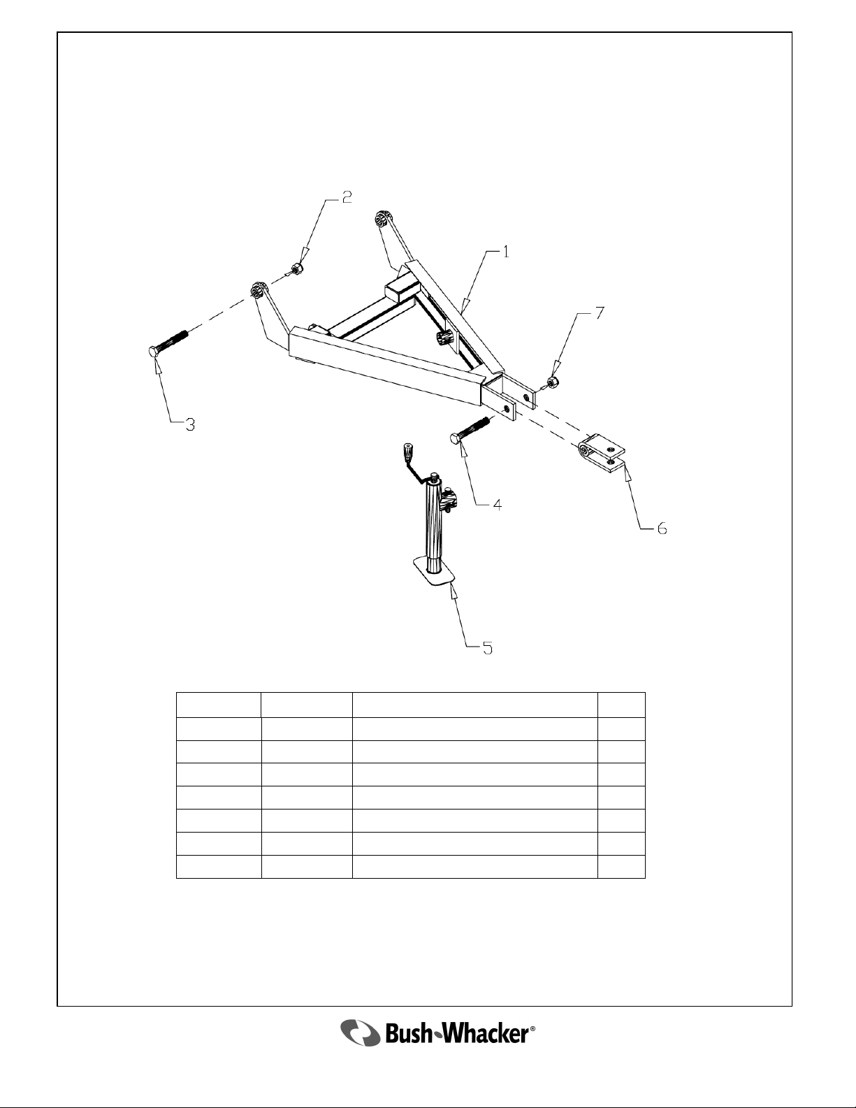
Tongue with Fixed Clevis
Ref. No. Part No. Description Qty
1 5680 Regular Tongue Only 1
2 3374 Nut 2
3 3373 Bolt 2
4 2624 Bolt 1
5 2969 Jack 1
6 3381 Clevis 1
7 2638 Nut 1
2010 ST-104
39
Page 40
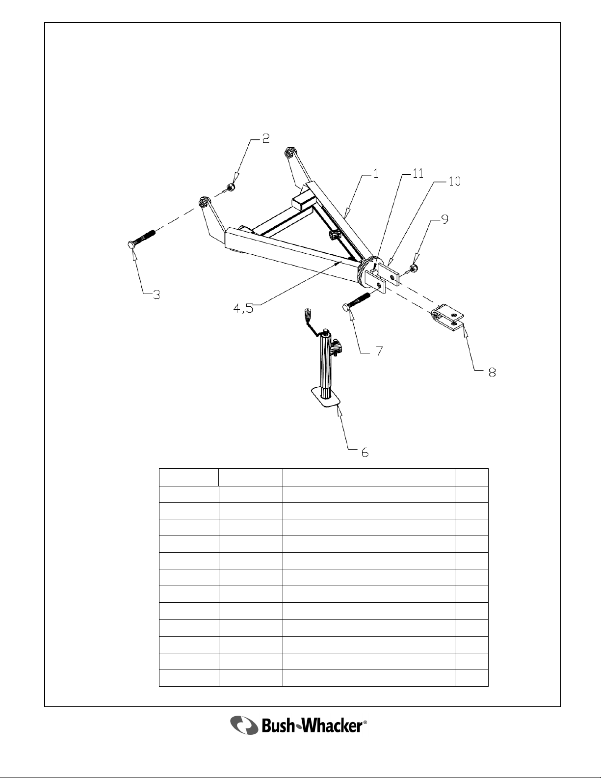
Tongue Assembly with Swivel Clevis
Ref. No. Part No. Description Qty
1 5662 Swivel Tongue Only 1
2 3374 Nut 2
3 3373 Bolt 2
4 2077 Nut 1
5 3285 Washer 1
6 2969 Jack 1
7 2624 Bolt 1
8 3381 Clevis 1
9 2638 Nut 1
10 3873 Swivel Only 1
11 2076 Bolt 1
12 5639 Set screw 1
40
2010 ST-104
Page 41
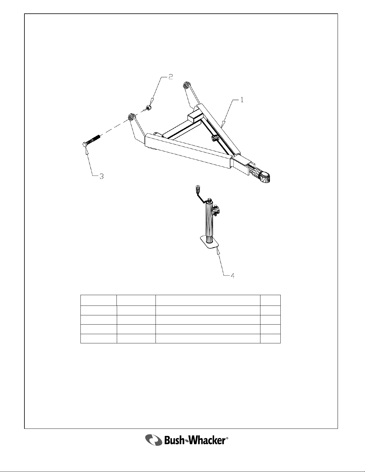
Tongue Assembly with Bulldog Hitch
Ref. No. Part No. Description Qty
1 5681 Bulldog Tongue Assembly 1
2 3374 Nut 2
3 3373 Bolt 2
4 2969 Jack 1
2010 ST-104
41
Page 42
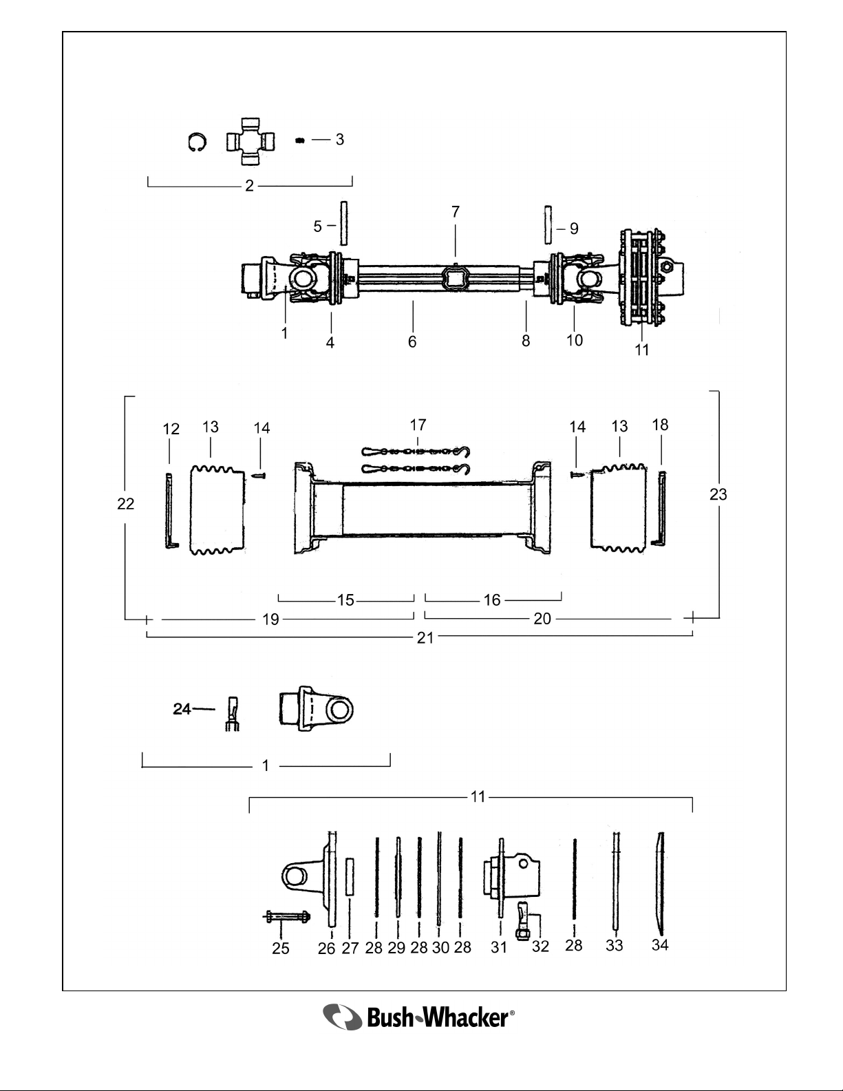
4059 Complete Drive Shaft
For Pull Type
42
2010 ST-104
Page 43
4059 Complete Drive Shaft
For Pull Type
Parts List
Ref. No. Part No. Description Qty
1 4006
2 3941
3 3917
4 3942
5 3919
6 4007
7 4008
8 4009
9 3922
10 3945
11 4041 Complete Clutch Assembly 1
12 3927 Outer Shield Ring 1
13 3947
14 3928
15 4011
16 4095
17 4012
18 3932
19 4013
20 4014
21 4015
22 4016
23 4017
24 3925
25 1719
26 4018
27 3962
28 3963
29 3964
30 3965
31 4049
32 3967
33 3968
34 3969
Quick Disconnect Yoke
Cross Kit
Grease Fitting
Outer Tube Yoke
Outer Roll Pin
Outer Tube (Steel)
Grease Fitting
Inner Tube (Steel)
Inner Roll Pin
Inner Tube Yoke
Shield Bell
Shield Screw
Outer Shield Tube
Inner Shield Tube
Shield Safety Chain
Inner Shield Ring
Outer Shield Complete
Inner Shield Complete
Complete Shield Assembly
Outer Half Shaft Complete
Inner Half Shaft Complete
QD Pin
Bolt w/Nut
Flange Yoke
Bushing
Clutch Disk
Clutch Plate
Inner Plate
Splined Hub
Bolt w/Nut
Outer Plate
Spring
1
2
1
1
1
1
1
1
1
1
2
6
1
1
2
2
1
1
1
1
1
1
8
1
1
2
1
1
1
1
1
1
2010 ST-104
43
Page 44
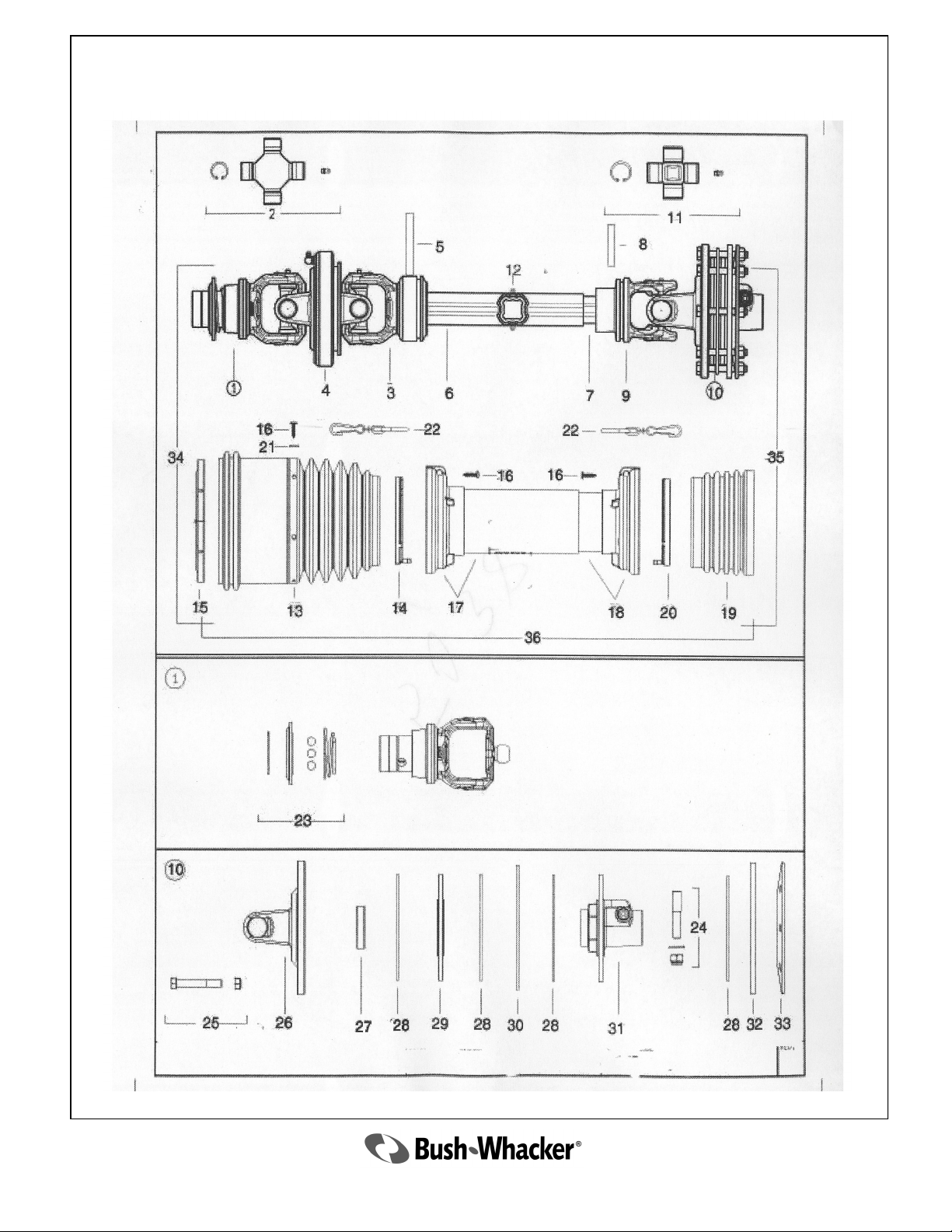
5038 Constant Velocity Drive Shaft
44
2010 ST-104
Page 45
5038 Constant Velocity Drive Shaft
Parts List
Ref. No. Part No. Description Qty
1 4892 Yoke 1
2 4893 CV Cross Kit 2
3 4896 Outer Tube Yoke 1
4 4897 CV Body 1
5 4898 Outer Roll Pin 1
6 5047 Outer Tube ( Steel ) 1
7 5048 Inner Tube (Steel) 1
8 4899 Inner Roll Pin 1
9 4900 Inner Yoke Tube 1
10 5049 Complete Clutch Assembly 1
11 4902 Cross Kit W/ Zert 1
12 4937 Grease Fitting 2
13 5055 Outer Shield Cone 1
14 4904 Shield Support Outer Tube 1
15 4905 Shield Support 1
16 5050 Shield Screw 12
17 5051 Outer Shield Tube 1
18 5042 Inner Shield Tube 1
19 4908 Inner Shield Cone 1
20 4909 Shield Support Inner Tube 1
21 4938 Washer 6
22 5061 Shield Chain 2
23 4910 Ball Collar Kit 1-3/8‖ 1
24 5054 Pin + Nut 1
25 5056 Bolt + Nut 1
26 5057 Yoke Flange 1
27 5058 Bushing 1
28 5059 Lining 4
29 5060 Lining Support 1
30 5062 Inner Plate 1
31 5063 Splined Hub 1
32 5064 Disc 1
33 5066 Belleville Washer 1
34 5067 CV Half Shaft Complete 1
35 5068 Inner Half Shaft Complete 1
2010 ST-104
45
Page 46
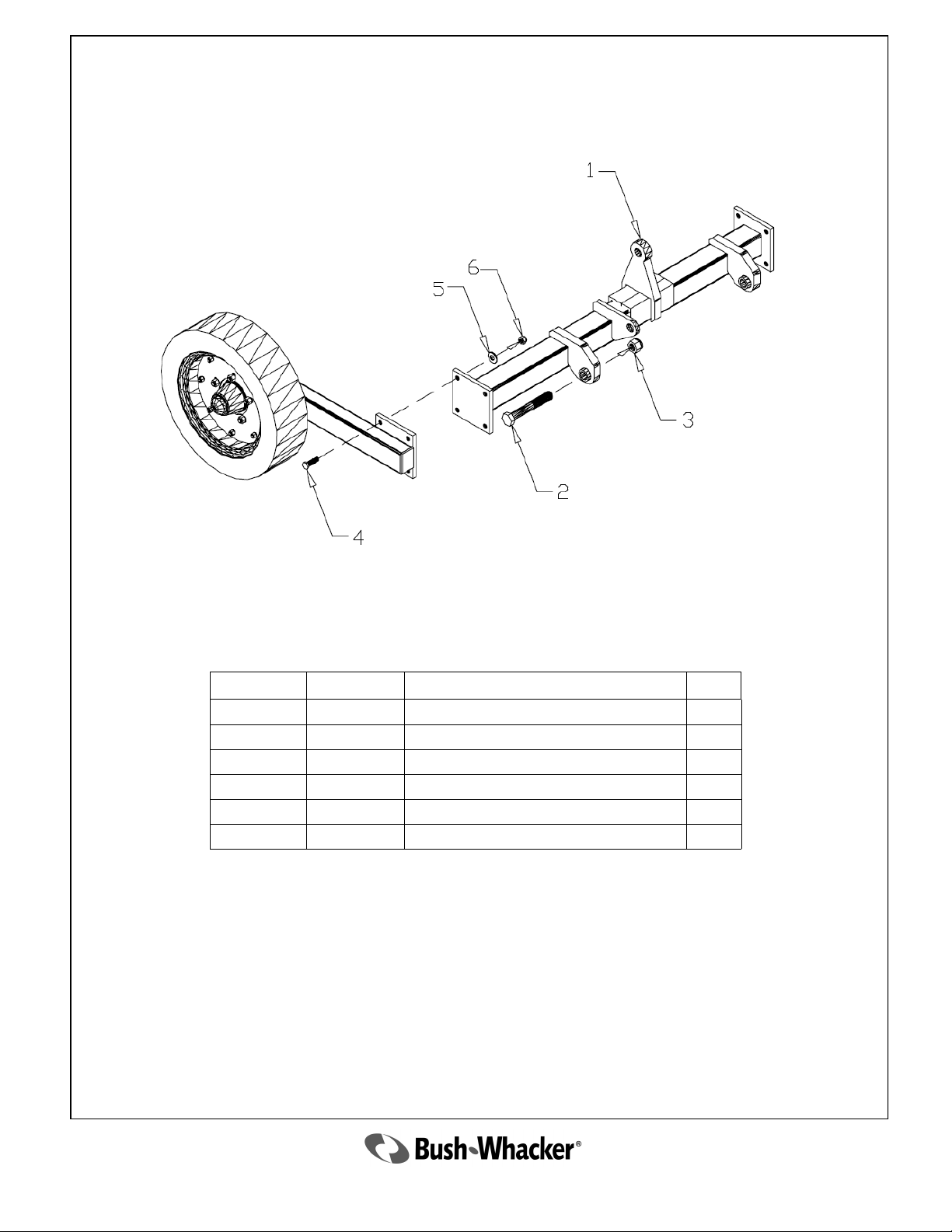
Rear Pivot Assembly for Pull Type
Ref. No. Part No. Description Qty
1 5661 Rear Pivot 1
2 3389 Bolt 2
3 2638 Nut 2
4 2335 Bolt 8
5 2337 Washer 8
6 2336 Nut 8
46
2010 ST-104
Page 47
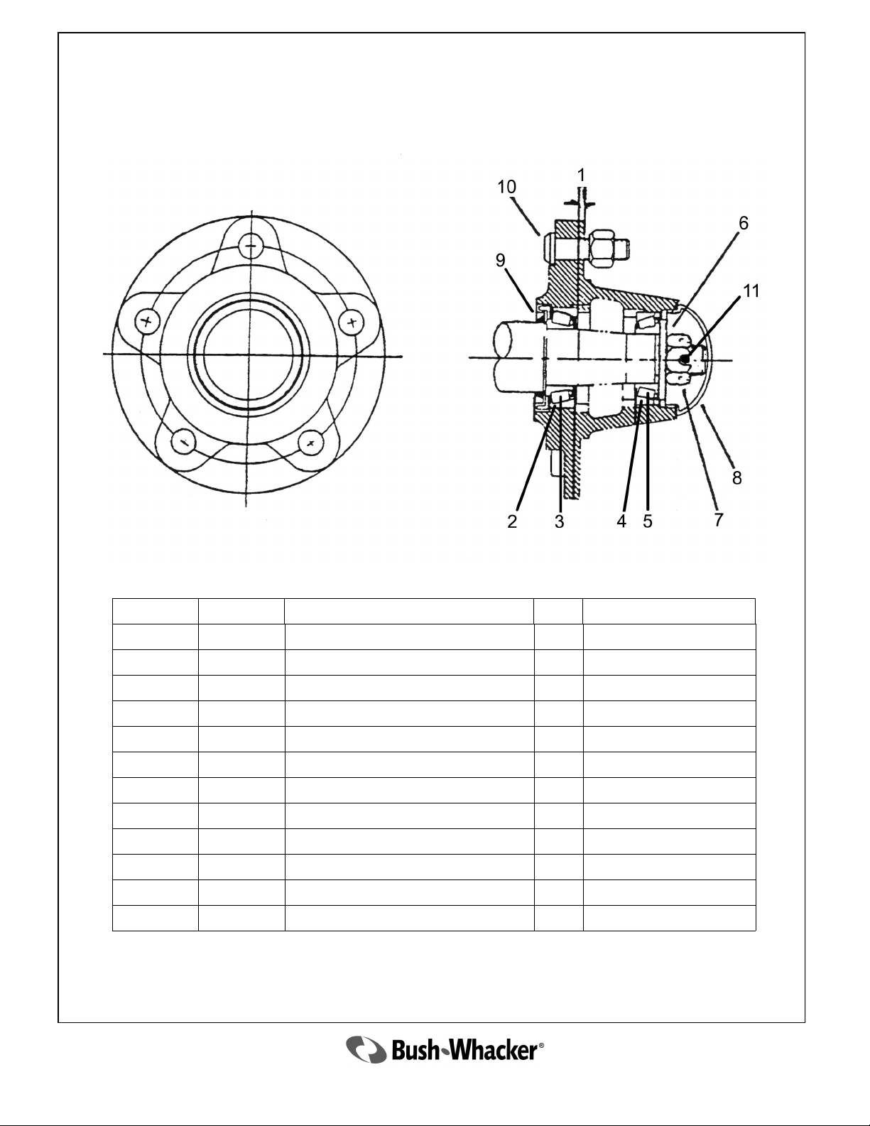
2448 Hub Assembly
Ref. No. Part No. Description Qty Remarks
2448 Complete Hub Assembly REF Includes Items 2-5,9,10
1 2449 Hub with Cups and Studs only 1
2 2450 Inner Race 1
3 2451 Inner Bearing 1
4 2452 Outer Race 1
5 2453 Outer Bearing 1
6 3359 Spindle Washer 1
7 3372 Spindle Nut 1
8 2456 Dust Cap 1
9 2457 Seal 1
10 2458 Stud Bolt with Nut 5
3360 Cotter Pin 1
47
2010 ST-104
Page 48
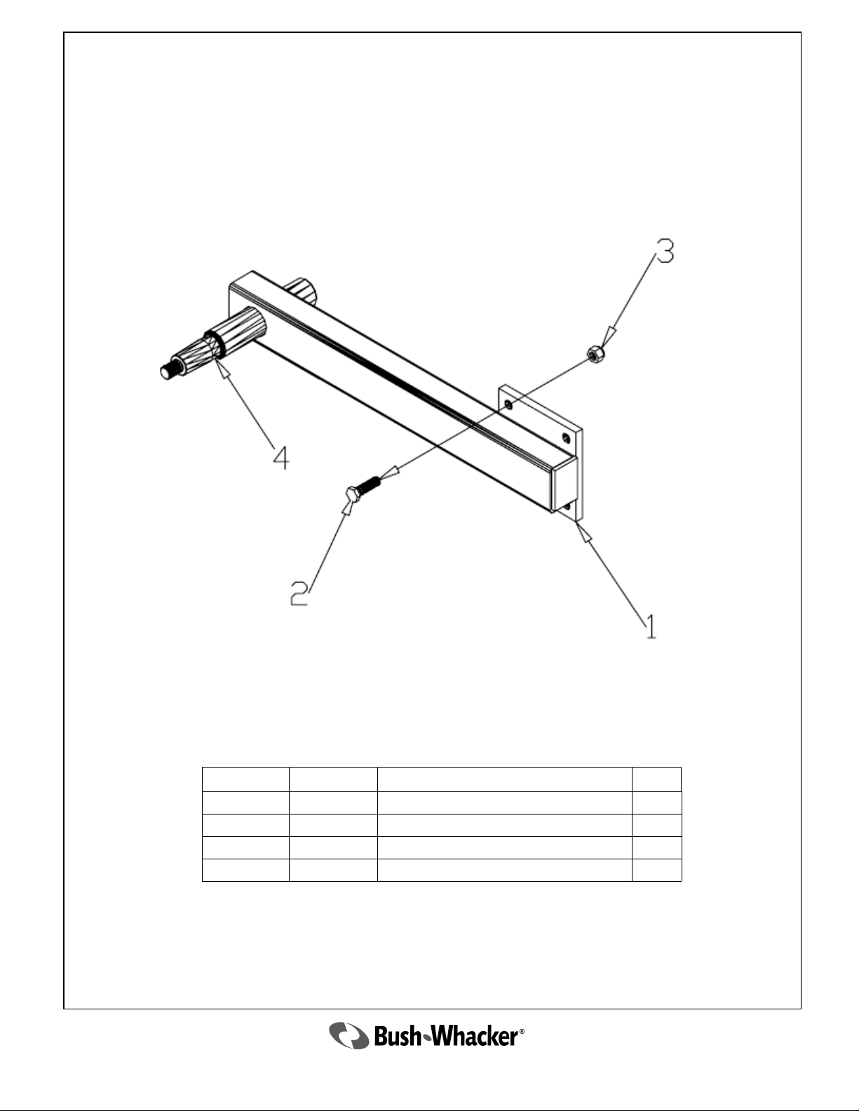
Axle Arm Assembly
Ref. No. Part No. Description Qty
1 3563 Axle Arm 1
2 2335 Bolt 4
3 2336 Nut 4
4 3564 Spindle 1
48
2010 ST-104
Page 49
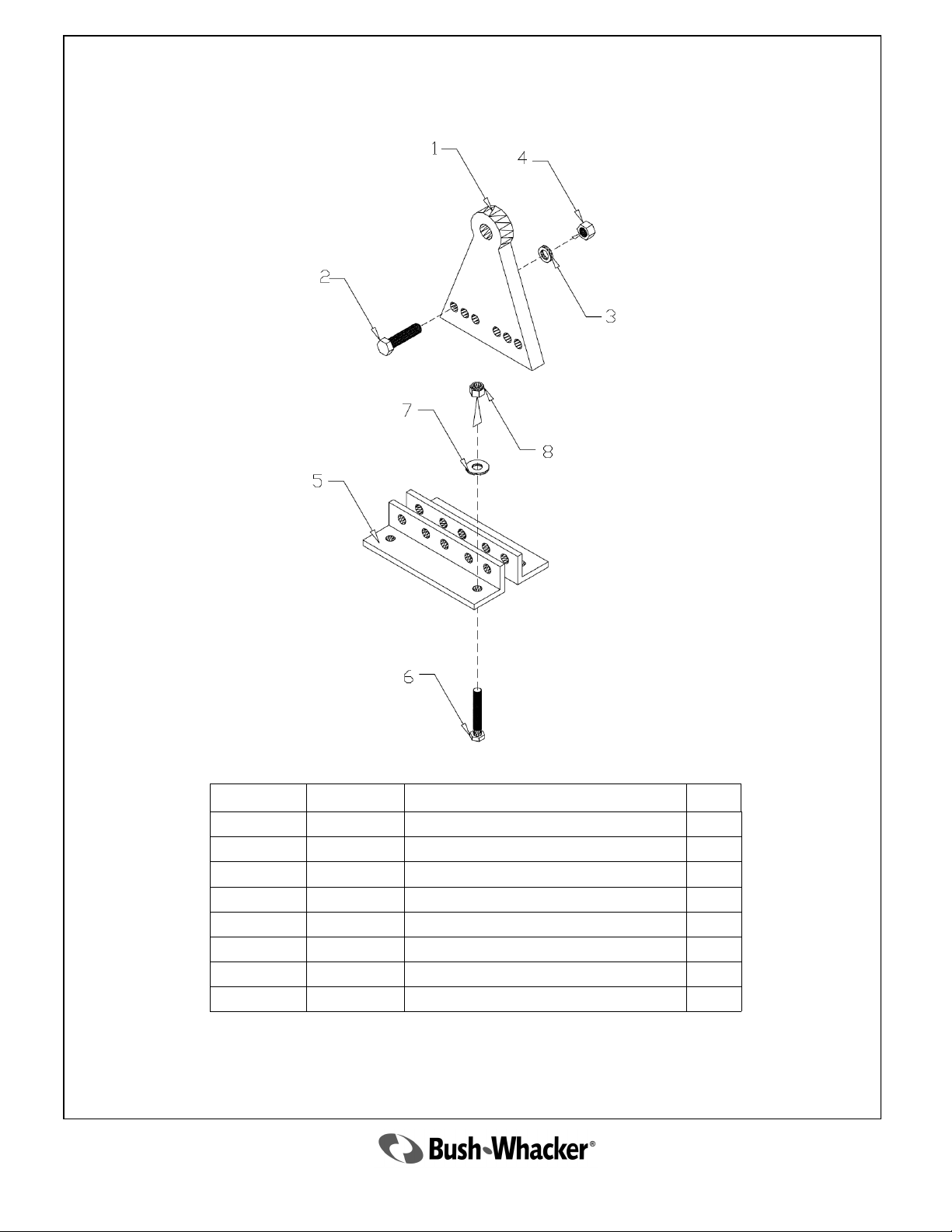
Cylinder Mounting Assembly
Ref. No. Part No. Description Qty
1 3385 Cylinder Block 1
2 3147 Bolt 2
3 3718 Washer 2
4 3148 Nut 2
5 3879 Adjusting Bracket 2
6 2335 Bolt 4
7 2337 Washer 4
8 2336 Nut 4
2010 ST-104
49
Page 50
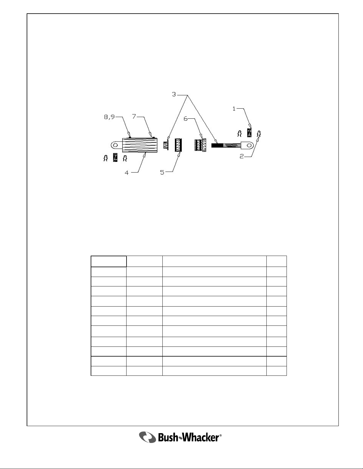
3387 Lift Cylinder
Ref. No.
1
2 3270 Clip Pin 4
3 3152 Rod w/Lock Nut 1
4 3157 Barrel Assembly 1
5 3158 Piston 1
6 3159 Gland 1
7 3165 Breather Plug 1
8 3330 Restrictor 1
9 4978 Hose 1
REF 3166 Seal Kit 1
REF 3167 Stroke Control Segment Kit AR
Part No. Description Qty
2330 Pin 2
50
2010 ST-104
Page 51
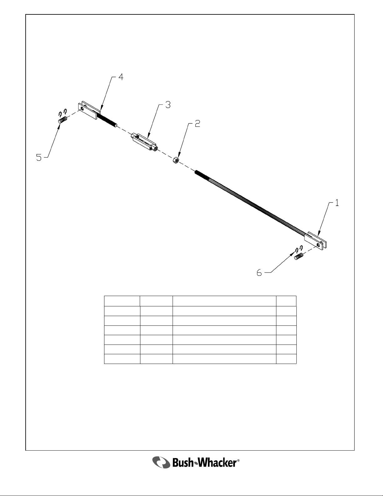
Level Rod Assembly
Ref. No. Part No. Description Qty
1 5638 Front Level Rod 1
2 2322 Nut 1
3 2321 Turnbuckle 1
4 3066 Rear Level Rod 1
5 2354 Pin 2
6 3270 Clip Pin 4
2010 ST-104
51
Page 52
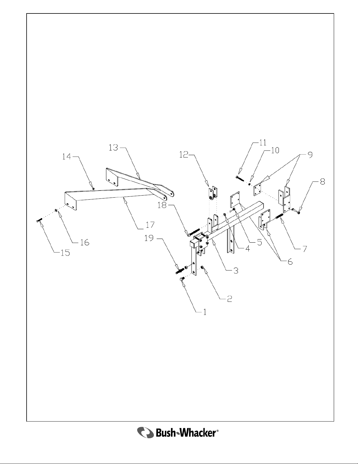
Offset Adapter Assembly
52
2010 ST-104
Page 53
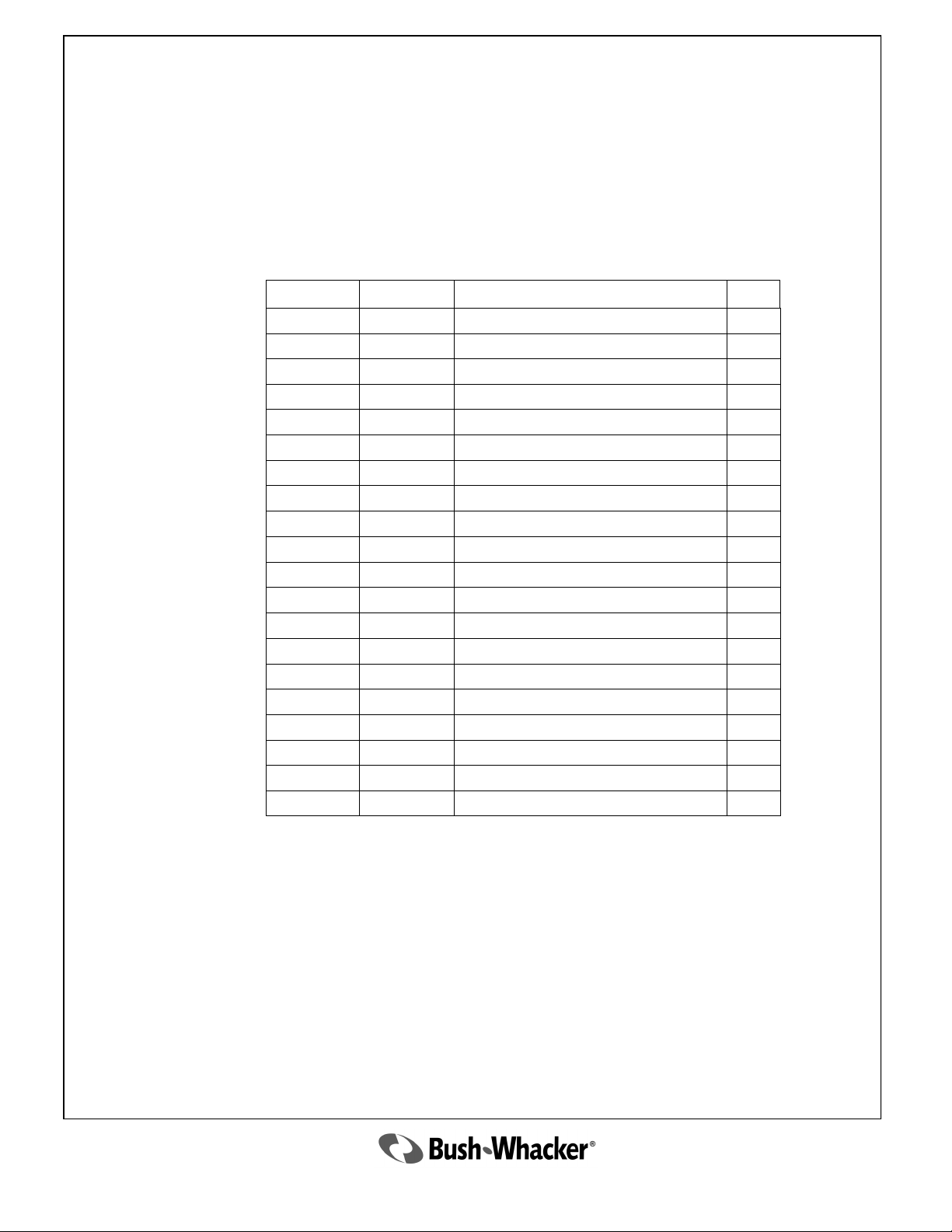
Offset Adapter Assembly
Parts List
Ref. No. Part No. Description Qty
1 3373 Bolt 2
2 3374 Nut 2
3 4390 Offset Adapter 1
4 3285 Washer 1
5 2077 Nut 1
6 2768 Adjustable Lift Guide 2
7 2765 Hitch Pin 2
8 2336 Nut 12
9 3688 Adjustable Three Point Mount 1
10 2337 Washer 12
11 2772 Bolt 12
12 3287 Category I Clevis 1
4860 Category II Clevis 1
13 4393 Left Brace 1
14 3148 Nut 4
15 3297 Bolt 4
16 3718 Washer 4
17 4394 Right Brace 1
18 3284 Bolt 1
19 C222 Hitch Pin 2
2010 ST-104
53
Page 54
Items not Illustrated
For Pull Type Only
Part No. Description Qty
2484 Standard Solid Rubber Tire REF
2489 Rim for 2490 Tire REF
2490 26‖ Aircraft Type Tire Assembly REF
2622 Foam Filled Tire, Implement REF
3275 26‖ Aircraft Tire Only REF
3276 Tube for 26‖ Aircraft Tire REF
3516 Foam Filled Aircraft Tire Assembly REF
3083 Access Cover 2
54
2010 ST-104
Page 55

HALL MANUFACTURING WARRANTY POLICY FOR BUSH-WHACKER ROTARY MOWERS
NEW EQUIPMENT WARRANTY
Subject to limitations and exclusions set forth herein, Hall Manufacturing Inc. warrants that if any component or
part of a machine manufactured by Hall Manufacturing, excluding any mechanical gearbox or mechanical
gearbox component used by Hall Manufacturing, proves to be defective in material or workmanship within one
(1) year from the delivery date of the original sale to the end user, Hall Manufacturing will, at its option, either
repair or replace the defective part without charge. In addition, Hall Manufacturing warrants that if any mechanical gearbox or mechanical gearbox component used by Hall Manufacturing on any Bush-Whacker rotary
mower proves to be defective in material or workmanship within three (3) years from the delivery date of the
original sale, Hall Manufacturing will, at its option, either repair or replace the defective mechanical gearbox or
gearbox part without charge, except for rotary mowers sold directly to a state or related governmental agencies
for which the mechanical gearbox or mechanical gearbox component warranty period is limited to one (1) year
from the delivery date of the original sale. No payment will be made in lieu of repair of the machine.
LIMITATIONS AND EXCLUSIONS
If the equipment is used for rental the warranty period is ninety (90) days from the date of sale to the renter. This
includes all mechanical gearboxes and their components.
This limited warranty covers defects in materials and workmanship in the parts manufactured or used by
Hall Manufacturing excluding:
Damage resulting from accident, abuse, misuse, neglect or other than normal and ordinary use of the
equipment.
Damage resulting from failure to use the product in accordance with the manufacturer’s instructions.
Refer to the appropriate owner’s manual for the Bush-Whacker mower model you purchased.
Hall Manufacturing shall be released from all obligations and liabilities under this warranty if:
The equipment had been operated with any accessory, equipment, component or part not manufactured by
Hall Manufacturing or approved for use by Hall Manufacturing.
The equipment has been repaired, altered or modified without Hall Manufacturing’s approval or if the
equipment shall have been operated subsequent to its involvement in an accident or breakdown un-
less the Owner furnishes reasonable evidence that such repair, alteration, modification or operation
subsequent to its involvement in an accident or breakdown was not a cause of the defect.
The Owner does not return, at Owner expense, the defective accessory, equipment component or machine
to, or notify, an authorized Bush-Whacker dealer. The Owner shall be responsible for submission of
reasonable evidence of proof of Date Discovery of said defect.
REPLACEMENT PARTS WARRANTY AND PARTS REPLACED BY WARRANTY
Hall Manufacturing further warrants that if any genuine Bush-Whacker part or component utilized by an authorized
Bush-Whacker dealer proves to be defective in material or workmanship, within thirty (30) days of such utilization, Hall Manufacturing will, at its option, repair or replace the defective part without charge. Owner shall
be responsible for all freight charges including labor to and from the place where the warranty work is performed.
WHAT YOU MUST DO TO ENFORCE THIS WARRANTY
Warranty services must be performed or approved by an authorized Bush-Whacker Dealer. The Owner must, at the
Owner’s expense, deliver, mail or ship the defective product together with the original Bill of Sale to any Authorized Dealer in the Owner’s area.
Owner must pay any postage, shipping charges, insurance costs, freight and other expenses to and from the place
where the warranty work is performed. If required to return equipment or any component or part to an authorized Bush-Whacker Dealer, Owner shall be obligated to pay any premium payable for overtime labor if overtime is incurred as a result or a request by the Owner.
UNAPPROVED SERVICE OR MODIFICATION
All obligations of Hall Manufacturing under this warranty shall be terminated if:
Service is performed by someone other than a Dealer authorized by Hall Manufacturing
Equipment is modified or altered in ways not approved by Hall Manufacturing.
ACCIDENTS AND NORMAL MAINTENANCE
This warranty covers only defective materials and workmanship. It does not cover depreciation or damage caused by
normal wear, accident, improper maintenance, improper protection in storage or improper use. The cost of normal
maintenance and replacement of service items such as: cutting parts, drive line cross kits and clutch pads, skid shoes,
gearbox and drive line shields, tires, bearings, seals, chains, etc. shall be paid for by the Owner.
2010 ST-104
55
Page 56

HALL MANUFACTURING WARRANTY POLICY FOR BUSH-WHACKER ROTARY MOWERS
DISCLAIMER OF IMPLIED WARRANTIES & CONSEQUENTIAL DAMAGES
Hall Manufacturing’s obligation under this limited warranty, to the extent allowed by law, is in lieu of all warranties,
Implied or expressed, INCLUDING IMPLIED WARRANTIES OF MERCHANTABILITY AND FITNESS FOR
A PARTICULAR PURPOSE and any liability for incidental and consequential damages with respect to the sale or use
of the equipment warranted. Such incidental and consequential damages shall include but not limited to: transportation
charges loss of income; rental of substitute equipment, and expenses due to loss, damage, detention or delay in the delivery of equipment or parts resulting from acts beyond the control of Hall Manufacturing.
IMPROVEMENTS OR CHANGES
Hall Manufacturing reserves the right to make improvements of changes in design and specification at any time without
incurring any obligation to owners of units previously sold.
WARRANTY CLAIMS PROCEDURE
Warranty claims must be delivered to Hall Manufacturing within thirty (30) days after the warranty service work was
performed.
Hall Manufacturing will approved or deny claim within thirty (30) days of receiving a claim.
Hall Manufacturing will issue credit for all genuine Bush-Whacker parts or components as well as all approved
Dealership employee labor time at a rate of $30.00 per hour within thirty (30) days of the claim approval.
Defective parts must be held for inspection for ninety (90) days after the work is performed. Hall Manufacturing
may request that parts be returned to the Hall Manufacturing factory for inspection.
ACKNOWLEDGEMENT REQUIRED
Hall Manufacturing shall have no obligation under this warranty unless the Owner Registration Card, included with your
Operators Manual, is signed by Owner and Dealer or Dealer’s Agent and is delivered along with a copy of the original
Bill of Sale from the Dealer to Hall Manufacturing within sixty (60) days from the date of sale.
─ ─ ─ ─ ─ ─ ─ ─ ─ ─ ─ ─ ─ ─ ─ ─ ─ ─ ─ ─ ─ ─ ─ ─ ─ ─ ─ ─ ─ ─
COMPLETE THE WARRANTY REGISTRATION CARD
(ON THE FOLLOWING PAGE)
PLACE IN AN ENVELOPE ALONG WITH THE ORIGINAL BILL OF SALE
MAIL TO:
HALL MANUFACTURING, INC.
P. O. BOX 5638
NORTH LITTLE ROCK, AR 72119
56
2010 ST-104
Page 57

WARRANTY REGISTRATION
** Return to Hall Manufacturing within sixty (60) days of purchase
Date of Purchase ___________ Purchaser _____________________________
Address __________________ City_____________________ State ________
Product ___________________ Model#___________ Serial#_____________
Dealer
Address
City State
Signature of Original Buyer Signature of Dealer or Dealer’s Agent
* Please include a copy of the original bill of sale
Page 58

Page 59

Notes
2010 ST-104
59
 Loading...