


Save This Manual for Future Reference
Original Instruction
Log Splitter
Operator’s Manual
MODEL NUMBER :
SERIAL NUMBER :
Both model number and serial number may be found on the main
label. You should record both of them in a safe place for future use.
FOR YOUR SAFETY
READ AND UNDERSTAND THE ENTIRE MANUAL BEFORE
OPERATING MACHINE
8
30 TON
LOG SPLITTER

2
LOG SPLITTER
TABLE OF CONTENTS INTRODUCTION
ite ia ll it e
e ate an t p
u
Carefully read through this entire
operator' s m anual b efore usin g
your new unit. Pay attention to all
cautions and warnings.
This unit is a
engine driven hydraulic
log splitter. It is designed to split wood logs
for use as firewood for a stove or fireplace.
This log splitter will only split logs lengthwise
with the grain.
Engine Manual
The Engine Manufacturer is responsible for
all engine-related issues with regards to
performance, power rating, specifications,
warranty and service. Please refer to the
Eng ine Manufacturer ’ s owner/ o perato r’s
manual, packed separately with your unit,
or
more information.
Introduction 2
Specifications 3
Symbols 4
Safety 5
Contents Supplied 9
Assembly 10
Know Your Machine 14
Operation 16
Transporting 19
Maintenance 20
Storage 21
Warranty 21
Troubleshooting 22
Parts Diagram 23
Notes 26

3
LOG SPLITTER
*Splitting force and cycle times may vary depending on mechanical and environmental conditions.
Specifications
Model # LS301
Splitting Force* 30 ton
Log Capacity 655 mm
Engine Kohler Command Pro CH395
Displacement 277 cc
Gross Torque @ 2600rpm 20 ONM
Fuel Capacity 7 L
Engine Oil Capacity 1.3 L
Starting System Recoil
Control Valve Auto Return with Adjustable Detent
Pump Size 17 GPM
Hydraulic Cylinder Bore
115 mm
Hydraulic Cylinder Stroke 610 mm
Hydraulic Rod Diameter 45 mm
Cylinder Cycle Time* 10.9 seconds
Hydraulic Capacity 22.5 L
Hydraulic Oil Included Pre-filled with premium hydraulic fluid
Replacement Filters Built-in, Sealed, Return Filter, Suction Screen
Hoses High pressure w/wire braid; Coil-wrapped
Beam Heavy duty U-shape formed construction
Wedge Size 190mm
Wedge Style 2-way
4-Way Wedge Optional
Rear Wheels 4.80-8, DOT Approved 16” O.D. Road Tyres
Hitch Coupler 2” Ball with Safety Chains
Safety Chains Standard
Max Towing Speed 50 kmh
Hitch Handle Standard
Horizontal/Vertical Splitting Standard
Open Operating Zone Standard
Log Cradle Standard
Log Table Optional
Weight 278 kgs
Dimensions (LxWxH) 232x121x94cm

4
ENVIRONMENTAL
SYMBOLS
The rating plate on your machine may
show symbols. These represent important
information about the product or instructions
on its use.
Recycle unwanted materials instead
of disposing of them as waste. All
tools, hoses, and packaging should
be resorted, taken to t he local
recycling center and disposed of in
an environmentally safe way.
Read these instr u c tions
carefully.
Wear eye protection.
Wear hearing protection.
Wear protective gloves.
Wear safety footwear.
Do not remove or tamper
with the protection and safety
devices.
Don’t stand or sit on the log
splitter.
Opera te the l og splitter on
level surfaces. Stay off slopes
and slippery surfaces.
Do not touch parts that are
hot from operation. Serious
burns may result.
No smoking, sparks, or flames.
Properly dispose of waste oil!
HYDRAULIC
OIL
FILLING
MAX.
MIN.
REVERSE
FORWARD
N
Keep children and bystanders
o and away from the log
splitter.
Be sure the engine's switch is
o before transporting the
machine or performing any
maintenance.
Keep hands and fingers away
from all pinch points.
Never remove partially split
wood from the wedge with
your hands. Fingers may
become trapped between the
split wood.
Keep hands away from
moving parts. Moving parts
can crush or cut.
Keep feet away from moving
parts. Moving parts can crush
or cut.
Always keep body and hands
away from pin holes or nozzles
that eject hydraulic fluid under
pressure. Escaping hydraulic
fluid can puncture skin and
cause blood poisoning.
Thrown objects.
Check and fill hydraulic oil.
Follow the direction indicated
to use the control lever.
For logs that are not cut
square, the longest portion of
the log should be rotated
down and the most square
end placed toward the end
plate.
LOG SPLITTER

LOG SPLITTER
5
a responsible adult.
Do not operate the machine while under the
influence of drugs, alcohol, or any medication
that could affect your ability to use it properly
.
Dress properly. Wear heavy long pants, boots,
and gloves. Do not wear loose clothing, short
pants, or jewellery of any kind. Secure long
hair so it is above shoulder level. Keep your
hair, clothing, and gloves away from moving
parts. Loose clothes, jewellery, or long hair
can be caught in moving parts.
Protect eyes, face, and head from objects that
may be thrown from the unit. Always wear
safety goggles or safety glasses with side
shields when operating.
Wear appropriate hearing protection.
Always keep hands and feet away from
all moving parts during operation. Moving
parts can cut or crush body parts.
Always keep hands and feet away from all
pinch points.
Do not to uch parts that might be hot
from operation. Allow parts to cool before
attempting to maintain, adjust, or service.
Stay alert, watch what you are doing, and use
common sense when operating the machine.
Do not overreach. Do not operate the
machine whil
e barefoot or when wearing
sandals or similar lightweight footwear.
Wear protective footw ear that will
protect you r feet an d improve your
footing on slippery surfaces. Keep proper
footing and balance at all times. This enables
better control of the machine in unexpected
situations.
Inspect your Machine
Check your machine before starting it. Keep
guards in place and in working order. Make
sure all nuts, bolts, etc are securely tightened.
Never operate the machine when it is in need
of repair or is in poor mechanical condition.
Replace damaged, missing, or failed parts
before using it. Check for fuel leaks. Keep the
machine in safe working condition.
Do not
use the machine if the engine’s switch
does not turn it on or off. Any p etrol
powered machine that can’t be controlled with
the engine switch is dangerous and must be
replaced.
SAFETY
General Safety Rules
Understand your Machine
Read this manual and labels affixed to the
machine to understand its limitations and
potential hazards.
Be thoroughly familiar with the controls and
their proper operation. Know how to stop the
machine and disengage the controls quickly.
Make sure to read and understand all the
instructions and safety precautions as outlined
in the Engine Manufacturer’s manual
packed separately with your unit. Do not
attempt to operate the machine until you
fully understand how to properly operate
and maintain the engine and how to avoid
accidental injuries and/or property damage.
If the unit is to be used by someone other than
original purchaser or loaned, rented, or sold,
always provide this manual and any needed
safety training before operation. The user can
prevent and is responsible for accidents or
injuries that may occur to themselves, other
people, and property.
Do not force the machine. Use the correct
machine for your application. The correct
machine will do the job more efficiently and
safer at the rate it was designed.
Personal safety
Do not permit children to operate this machine
at any time.
Keep children, pets, and other people not
using the unit away from the work area. Be
alert and shut off unit if anyone enters work
area. Keep children under the watchful care of
MAX. 50 KPH
Do not transport with objects on the machine.
Maximum towing speed of
ph.

6
tank indoors.
Keep grounded conductive objects, such as
tools, away from exposed, live electrical parts
and connections to avoid sparking or arcing.
These events could ignite fumes or vapors.
Always stop the engine and allow it to cool
before filling the fuel tank. Nev er remove
the cap of the fuel tank or add fuel while the
engine is running or when the engine is hot.
Do not operate the machine with known leaks
in the fuel system.
Loosen the fuel tank cap slowly to relieve any
pressure in the tank.
Never overfill the fuel tank. Fill the tank to no
more than 1/2” below the bottom of the filler
neck to provide space for expansion as the
heat of the engine can cause fuel to expand.
Replace all fuel tank and container caps
securely and wip e up spilled fu el. Never
operate the unit without the fuel cap securely
in place.
Avoid creating a source of ignition for spilled
fuel. If fu
el is spilled, do not attempt to start
the engine but move the machine away
from the area of spillage and avoid creating
any source of ignition until fuel vapors have
dissipated.
When fuel i s spilled on yourse lf or your
clothes, wash your skin and change clothes
immediately.
Store fuel in containers specifically designed
and approved for this purpose.
Store fuel in a cool, well-ventilated area, safely
aw ay from s parks, op en flames, or other
sources of ignition.
Never store fuel or a machine with fuel in the
tank inside a building where fumes may reach
a spark, open flame, or any other source of
ignition, such as a water heater, furnace, or
clothes dryer. Allow the engine to cool before
storing in any enclosure.
Hydraulic system safety
The hydraulic system of the machine requires
careful inspection along with the mechanical
parts. Be sure to replace frayed, kinked,
cracked, or otherwise
damaged hydraulic
hoses or hydraulic components.
Hydraulic fluid can result in severe burns. Fluid
Regularly check to see that keys and adjusting
wrenches are removed from the machine area
before starting it. A wrench or a key that is left
attached to a rotating part of the machine may
result in personal injury.
Avoid accidental starting. Be sure the engine’s
switch is off before transporting the machine or
performing any maintenance or service on the
unit. Transporting or performing maintenance
or service on a machine with its switch on
invites accidents.
If the machin e should start to v i brat e
abnormally , stop the engi ne (motor) and
check immediately for the cause. Vibration is
general
ly a warning sign of trouble.
Engine safety
This machine is equipped with an internal
combustion engine. Do not use on or near any
unimproved, forest covered, or brush covered
land unless the exhaust system is equipped
with a spark arrester meeting applicable local,
state, or federal laws.
Under Australian Law, a spark arrester is to
be fitted to the engine. A spark arrester, if
used, must be maintained in effective
working order by the operator.
Never start or run the engine inside a closed
are a. The e xhaust f umes a re
dan gerous , containing carbon monoxide, an
odorless and deadly . Operate this unit
only in a well-ventilated outdoor area.
Do not tamper with the engine to run it
at excessive speeds. The maximum engine
speed is preset by the manufacturer and is
within safety limits. See engine manual.
Keep a Class B fire extinguisher on hand when
operating this log splitter in dry areas as a
precautionary measure.
Fuel safety
Fu
el is highly flammable, and its vapors can
explode if ignited. Take precautions when
using to reduce the chance of serious personal
injury.
When refilling or draining the fuel tank, use
an approved fuel storage container while in
a clean, well-ventilated outdoor area. Do not
smoke, or allow sparks, open flames, or other
sources of ignition near the area while adding
fuel or operating the unit. Never fill the fuel
LOG SPLITTER
LOG SPLITTER
7
in the hydraulic system can penetrate skin
and result in serious injury or death. Be sure to
stop the engine and relieve hydraulic pressure
before doing any work on hydraulic parts.
Keep body and hands away from pin holes or
nozzles that expel hydraulic fluid when under
pressure. Use paper or cardboard, not hands,
to search for leaks.
Ensure all hydraulic fluid connections are tight
and all hydraulic hoses and lines are in good
condition before applying pressure to the
system.
Do not remove the cap from the hydraulic
tank or reservoir while the machine is running.
The tank could contain hot oil under pressure,
which could result in serious injury.
Do not adjust the pressure setting on the
hydraulic pump or valve.
If injured by escaping fluid, no matter how
small the wound is, see a doctor at once.
A typical injection injury may be a small
wound that does not look serious. However,
severe in
fection or reaction can result if
proper medical treatment is not administered
immediately by a doctor who is familiar with
injection injuries.
Specific Safety Rules
Preparation of the log
Both ends of the log should be cut as square
as possible to prevent the log from rotating
out of the splitter during operation.
Never split logs greater than the specified log
capacity.
Do not operate the log splitter on icy, wet,
muddy, or slippery ground. Only operate your
log splitter on level ground.
Operating on a slope could cause
the log splitter to roll over or logs
to fal l o the equipment, which
could result in injury.
Do not move the log splitter ov er hilly or
uneven terrai n wi thout a t ow v ehicle or
adequate help.
Keep the work area free of clutter. Remove
spl i t wood from a r ound the log splitt e r
immediately after each use to avoid potential
tripping.
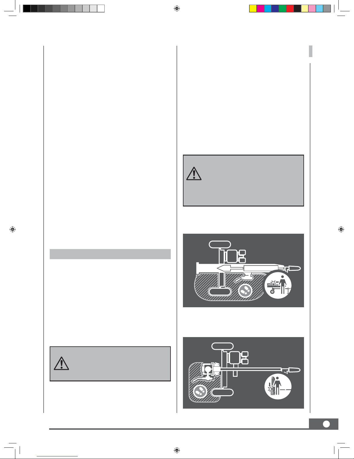
Operator zone
This unit is designed to be operated by one
person located in the operator zone as shown
in the following diagrams.
Operate the unit only when standing in the
operator zone.
Always stop the unit and allow moving parts
to stop before leaving operation zone. Do not
leave a running unit unattended.
Many accidents occur when more
than one person operates the log
splitter.
The adult who loads and stabilises
the log must be the person who
operates the control handle.
Horizontal operating position
Vertical operating position

8
Machine use and care
Never operate the machine without good
visibility or light.
Never attempt to split wood across the grain.
The log splitter was not designed for crossgrain splitting.
Al ways block the front and back of both
wheels to prevent unintended movement.
Hold the bark side of the logs when loading or
positioning, never the ends. Never place your
hands or any part of your body between a log
and any part of the log splitter.
Do not straddle or step over the log splitter
during operation.
Do not reach or bend over the log splitter to
pick up a log.
When stabilizing a log wi th the le ft hand,
remove your hand when the wedge contacts
the log or serious injury may occur.
Never attempt to split more than one log at a
time.
Do not attempt to load your log splitter when
the ram or wedge is in motion.
Use your hand to operate the control lever on
the valve. Do not use your foot, a rope, or any
extension device.
Do not move the log splitter while the engine
is running.
Towing safety
Check
all local and state regulations regarding
towing, licensing, and lights before towing
your log splitter.
Before towing the log splitter, check t
res
for excessive wear, cuts, or damage. Check
for proper t
re inflation. Add air as
required. Do not over inflate t
res. Serious
injury can result if t res explode.
Check before towing to make sure the log
splitter is correctly and securely attached to
the towing vehicle and the safety chains are
secured to the hitch or bumper of the vehicle
with enough slack to allow turning. Always use
a class I, 2" ball with this log splitter.
Make sure the coupler is tight before towing
and after towing 50
LOG SPLITTER
Never transport cargo on the log splitter.
Never allow anyone to ride or sit on the log
splitter.
Always stop the engine, lock the beam in the
horizontal position, and close the fuel shut-off
valve when transporting the unit.
Use extra care when towing the log splitter.
Do not exceed 50 kph. Towing the log splitter
at a speed greater than 50 kph could result
in loss of control, damage to the
equipment, serious injury, or death.
Avoid sharp turns and steep angles. Avoid
lar ge holes o r ditches when towing t h e
equipment. Always be careful when backing
up with your log splitter when to wing; it
could jackknife. Use caution when backing
up; a spotter outside the vehicle is highly
rec
ommended. Disconnect the log splitter
from the towing vehicle before operating it.

LOG SPLITTER
9
CONTENTS SUPPLIED
1. Beam with Cylinder
2. Reservoir with Engine
3. Beam Lock Bracket
4. Pivot Bracket
5.
Log Cradle (Left)
6.
Log Cradle (Right)
7.
Wheels
8.
Tow Bar
9. Manual Tube
10. Operator’s Manual and Engine Manual
11.
Tools for Spark plug Assembly
12.
Log Table (Optional)
13. Hardware Kit, Including:
3
4
7
9
8
OPTIONAL
12
11
10
2
1
6
5
13
Your log splitter comes partially assembled and contains the following:
OPTIONAL
M22 X 2
A
4 X 50
X 2
X 2
M12 X 90 X 2 B
M10 X 25 X 4 C
20 X 110 X 1
D
Bridge Pin X 1
M10 X 25 X 2 E
M8 X 20 X 2 F
M12 X 35 X 8 G
M10 X 25 X 4 H

LOG SPLITTER
10
This log splitter was partially assembled at the
factory. To assemble your machine follow the
below instructions.
WHEELS
ASSEMBLY
Remove the anti-dust sleeves from the two
wheels. Take the anti-dust washers and
roller bearings from the wheels and set
aside for later use.
1.
At least two people are needed to move
the reservoir outside of the pallet. Place
the engine at the end corner of the pallet.
Remove the two anti-dust sleeves from the
wheel axle.
2.
3.
Assistant holds the engine, while the other
person assembles the wheel opposite of
the engine first.
4.
Slide the anti-dust washer and one roller
bearing onto the axle. Use a soft-faced
hammer to tap the roller bearing lightly
to make sure the bearing is in the right
position.
Slide the wheel with the valve stem facing
out to the wheel axle and the other roller
bearing, then put the wheel washer against
the bearing. Use a 32mm socket to tighten
the axle nut completely.
Spin the wheel
clockwise or counterclock
wise to ensure proper bearing seating.
Loosen the axle nut until it is loose enough
to turn the wheel with your fingers.
Retighten the axle nut until "finger tight."
Insert the cotter pin through the hole in the
axle. Bend open and spread the prongs in
5.
7.
8.
9.
10.
6.
An-dust Washer (x2)
An-dust Sleeve (x4)
Roller Bearing (x4)
Figure 1a
Reservoir with Engine
45
o
Use the shipping crate boom
for balancing when installing
the wheel assembly.
Figure 1b
An-dust Sleeve (x2)
Wheel Sha
Figure 1c
Axle Nut (x1)
Coer Pin (x1)
Roller Bearing (x2)
An-dust Washer (x1)
Wheel Washer (x1)
Wheel
Cap
(x1)
32
mm
Figure 1d
M22 X 2
A
4 X 50
X 2
X 2

LOG SPLITTER
11
opposite directions so the axle nut will not
come off (make sure the tyre spins freely).
Use a soft-faced hammer to tap the antidust washer in the right position.
Align the wheel cap against the wheel hub.
Use a soft-faced hammer to tap the wheel
cap onto the wheel hub properly.
Follow the same procedure to assemble
the other wheel (follow steps 4 – 12 under
wheel assembly.)
11.
13.
12.
Install ation of the cotter p in is
important and required. Failure
to install the cotter pin can result
in loss of wheel retention. Always
assemble using a new cotter pin. Do
not reuse.
Hold and pull the beam until the log cradle
mount and the beam is against the wooden
block in-pallet.
Slowly lift the top of the beam and stand
the beam on the end plate in the vertical
position.
1.
2.
BEAM
Aft er the beam and cyl inder
assembly is in the vertical position, a
helper is needed to prevent the beam
from tipping over until it is secured
on the hydraulic tank assembly with
the hitch pin and R-clip.
The beam assembly is heavy and
has a small foot print. When in the
vertical position, the beam may fall,
causing damage to the machine and
could result in personal injury.
TOW BAR
Insert the tow bar into the tank pivot mount. Align
the holes in the tow bar with the holes in the tank
pivot mount. Connect and tighten the tow bar to
the tank by using the M12x90 bolts, flat washers,
spring washer, and nuts. (See
Figure 3)
Figure 2a
Wooden Block
Log Cradle Mount
Beam
Figure 2b
Beam
M12x90 (x2)
Tank Assembly
Tow Bar
Tank Pivot Mount
M12 (x2)
18
mm
19
mm
30
mm
X 2
Figure 3
M12 X 90 X 2 B
SUPPORT LEG
Lift the tow bar slightly. Pull out the lock lever
and put the support leg in the DOWN position,
then release the lever and make sure the leg is
secured. Remove the bottom pallet.
Support Leg
Support Leg Lock
Liing Handle
Figure 4

SPLITTER
12
PIVOT BRACKET
Align the holes in the pivot bracket with the
holes on the beam and insert and tighten
bolts, spring washers, and flat washers.
The beam can be very heavy and
dangerous if it tips over and
may cause personal injury.
BEAM TO RESERVOIR
Make sure a helper holds on to the beam
to keep it from falling. Reposition the
beam and reservoir so the back of the tank
is facing the vertical beam as shown in
Figure 6a.
1.
Ali gn the pivot brac ket on the beam
assembly to the pivot mount on the tank
weldment and insert the beam pivot pin
and washer. (See
Figure 6b
)
2.
Insert the bridge pin through the hole in
the beam pivot pin.
3.
M10x25 (x4)
Pivot Bracket
Beam
Parallel Lines
16
mm
19
mm
Figure 5
Figure 6a
Beam Pivot Pin (x1)
Tank Pivot Mount
Washer (x1)
Bridge Pin (x1)
Pivot Bracket
Figure 6b
BEAM LOCK BRACKET
When mounting the lock latch assembly,
make sure the latch rod side of the bracket
is on the same side as the engine. Install
the beam lock bracket to the beam by
using the beam lock M10x25 bolts, spring
washer, and flat washers. (See
Figure 7a)
1.
M10x25 (x2)
Beam Lock Bracket
Beam
Parallel Lines
16
mm
19
mm
Figure 7a
M10 X 25 X 4 C
M10 X 25 X 2 E
20 X 110 X 1
D
Bridge Pin X 1

LOG SPLITTER
13
Hold the lifting handle and slowly lower the
beam. It will lock automatically. Double
check to make sure the beam bracket is
locked onto the beam.
2.
Do not let the beam suddenly drop.
Keep hand s and fingers clear of
pinch or crush points at all times.
MANUAL TUBE
LOG CRADLES
Remove the cap from the manual tube.
Align the holes in the manual tube with
the holes in the tow bar. Insert and tighten
bolts and washers. (See Figure 8)
Reattach the cap.
1.
2.
M12x35 (x8)
Log Cradle (Right)
Outside Holes
Inside Holes
Figure 9
18
mm
19
mm
30
mm
19
mm
Beam Lock Bracket
Figure 7b
M8x20 (x2)
Manual Tube
Cap
16
mm
13
mm
18
mm
19
mm
30
mm
Figure 8
2. Follow step 1 to assemble the left log cradle.
(See Figure 9)
1. Align the holes on the right log cradle to the
inside and lower holes on the beam mounts.
Insert the M12x35 bolts, flat washers, and
nuts and securely tighten.
M12 X 35 X 8 G
M8 X 20 X 2 F
LOG TABLE (OPTIONAL)
Refer to Figures 9 and 10 to install the work
table. Remove the bolts, flat washers, and nuts
from the inside holes. Move the log cradle
from the incline position to the horizontal
position. Align the holes on the log cradle
with the outside holes on the beam mount.
Reinstall the bolts, flat washers, and nuts.
Place the work table over the holes in the log
cradle and align the 4 holes from the work
table plate and log cradle. Insert and tighten
the M10x25 bolts, spring washers, flat washers,
and nuts.
M10x25 (x4)
Work Table
Outside Holes
Log Cradle (Right)
Inside Holes
M10 X 25 X 4
8
16
mm
18
mm
19
mm
30
mm
Figure 10

SPLITTER
14
KNOW YOUR MACHINE
Features and Controls
Log Stripper
Split Control Handle
4-Way Wedge(Optional)
Log Spinner Foot Plate
2-Position Log Cradle
Cylinder
Lifting Handle
Manual Tube
Reservior
Safety Chains
Control Valve
Hydraulic Breather/Dipstick
Beam Lock Bracket
Support Leg
Beam Assembly
2” Ball Hitch Coupler
Hydraulic Pump
Log Table (Optional)

LOG SPLITTER
15
Engine On/O Switch
Recoil Starter Handle
Choke Control
Fuel Shut-O Valve
Throttle Control
LOG SPINNER FOOT PLATE
The foot plate holds the log in place while
the wedge splits the log.
The foot plate allows the operato r to
easily spin a log in prep for splitting and
allows the log to rotate when splitting
instead of causing unnecessary stress on
the beam.
It is easy to replace when the grip teeth
are damage d . No repair weldi ng is
required.
2-POSITION LOG CRADLE
The log cradles are designed to catch the log
after it is split.
2-position function – The first positon is
to center logs on the beam. The second
position provid es a fla t s urface and
worktable on which to put logs.
SPLIT CONTROL HANDLE
The c ont rol handle i s u s ed to mo ve
the wedge up and down to split logs.
The control handle has three positions:
Forward, Neutral, and Reverse. See th
e
“operation” section for instruction.
MANUAL TUBE
Keep manuals safely in the tube.
BEAM LOCK BRACKET
The beam lock bracket is used to secure
the beam in the horizontal position.
LIFTING HANDLE
The liftin g handle is inclu ded for easy
transition from horizontal to vertical.
2” BALL HITCH COUPLER
The coupler h itch is at the end of the
tow bar and attaches to a tow ball for
transportation purposes.
4-WAY WEDGE(OPTIONAL)
The 4-way wedge is used to split the log
into four pieces at one time.
LOG STRIPPER
The log stripper is designed to remove
any partially split wood from the wedge.
This may occur while splitt ing large
diameter wood or freshly cut wood.
BEAM ASSEMBLY
The U-beam s tru c tura l de sign i s
significantly stronger than a typical I-beam
design.
LOG TABLE (OPTIONAL)
A log table/platform can be mounted on
the log cradle directly.
ENGINE ON/OFF SWITCH
The engine switch has two positions.
OFF - engine will not start or run.
ON - engine will start and run.

LOG SPLITTER
16
RECOIL STARTER HANDLE
The handle is used to start the engine.
FUEL SHUT-OFF VALVE
The fuel shut – off has two p osition.
CLOSED (
) - use t h is position t o
service, transport, or store the unit.
OPEN (
) - use this position to run the
unit.
CHOKE CONTROL
The choke control is used to choke the
carburetor and assi st in starting th e
engine. The choke control slides between
the CHOKE CLOSED
and CHOKE
OPEN
positions.
THROTTLE CONTROL
The throttle control regulates the speed
of the engine and will shut off the engine
when it is moved to the STOP position.
The throttle control moves between FAST
, SLOW , and S
TOP positions.
OPERATION
3. Using a funnel, add oil up to the FULL mark
on the dipstick. (See engine manual for oil
capacity, oil recommendation, and location
of fill cap.)
The engine is shipped without oil.
Do not start the engine before
adding oil.
Pet rol is highly flam mable
and explosive. You can be
burne d o r seriously injured when
handling fuel. Us e extreme care
when handling petrol.
Fill the fuel tank outdoors, never
indoors. Petrol vapors can ignite if
they collect inside an enclosure.
Explosion can result.
IMPORTANT: DO NOT OVERFILL!
This equipment and/or its engin e
may include evaporative emissions
c o n tr ol syst e m c omponent s ,
required to meet EPA and/or CARB
regulations, that will only function
properly when the fuel tank has been
fi lled to th e r ecommen ded
l eve l.
Overfilling may c ause permanent
damage to evaporative emissions
control system components. Filling
to the recommended level ensures
a vapor gap required to allow for
fuel expansion. Pay close attention
while filling the fuel tank to ensure
th at the recommended fuel lev el
inside the tank is not exceeded. Use
a portable petrol container with an
appropriately sized dispensing spout
when filling the tank. Do not use a
funnel or other device that obstructs
the view of the tank filling process.
DO NOT OVERFILL. Check engine
oil level daily and add as needed.
1. The engine must be off and allowed to cool
at least two minutes before adding fuel.
2. Remove the fuel filler cap and fill the tank.
(See engine manual for fuel capacity, fuel
recommendation, and location of fuel cap.)
ADD PETROL TO ENGINE
Many accidents occur when more than
one person operates the log splitter.
If a helper is assisting in loading logs
to be split, never operate the controls
until the helper is clear of the area.
2. Remove the oil fill
c ap/ dipstick t o
add oil.
CLOSEDOPEN
ADD OIL TO ENGINE
1. Make sure the log splitter is on a flat, level
surface.
3. Reinstall the fuel cap and tighten. Always
clean up spilled fuel.

LOG SPLITTER
17
The splitter wedge is designed
to reach the full extension before
contacting the foot plate.
To extend the life of the hydraulic
cylinder, avoid “bottoming out”
the wedge plate to the foot piece.
Cracks in logs can close quickly
and pinch fingers. Keep fingers
away from any cracks that open in
partially split logs.
Keep hands and fingers away from
the splitter wedge and log stripper
during cylinder retraction.
Never operate through the relief
valve for more than 5 seconds.
Forward position – Move the lever in this
direction to extend the cylinder toward the
spinner foot plate. Keep pressure on the lever
until the log splits. The lever does not lock in
this position. Release as soon as the log is split
or the cylinder is fully extended. (See Figure
11a and Figure 11b).
SPLIT CONTROL HANDLE
Neutral position – In this position the cylinder
does not move even though the engine is
running.
Reverse position – Move the lever in this
position to retract the cylinder. Push the lever
fully in this direction to lock it return mode. The
lever will automatically return to the neutral
position once the cylinder fully retracts.
Sudden stopping at a high speed,
under a heavy load, is not
recommended.
Engine damage may result.
STOP ENGINE
Return the cylinder to fully retracted position
or home position. Move the Throttle lever to
SLOW (
). Move the engine switch to OFF.
Close the fuel shut-off valve ( ).
If the engine is
hot, closing the
choke is not
necessary.
Rapid retraction of the starter cord
(kickback) will pull your handand arm
toward the engine faster than you
can let go. Broken bones, fractures,
bruises, or sprains could result.
STARTING ENGINE
OPENCLOSED
SLOWFAST
ONOFF
ONOFF
Make sure the control lever is in the neutral
position.
Pu l l the r ecoil s t art e r until engine
compression has become difficult to pull.
Let the recoil return to the home position,
then pull quickly to start the engine. Repeat
steps as needed. Fully open the choke and
set the throttle to the FAST position, before
operating the unit.
Move the engine
switch to the ON
position.
Open the fuel shutoff valve.
M ove t h e c hoke
lever to the CLOSED
position.
Move the throttle
lever slightly to the
FAST speed.
1.
6.
2.
3.
4.
5.

LOG SPLITTER
18
Reverse
Posion
Neutral Posion
Forward
Posion
Reverse Posion
Neutral Posion
Forward Posion
Liing Handle
Horizontal Beam Lock
1 2
Vertical Position
Rotating Position
Horizontal Position
CONVERSION BETWEEN HORIZONTAL
SPLIT TING PO SITION AN D V E R T ICAL
SPLITTING POSITION
STUCK LOG PROCEDURE
If a log does not split completely and becomes
stuck on the wedge, never attempt to
remove it by modifying the splitter or adding
attachments to the splitter.
Move the control lever to the Reverse positon
and allow the cylinder to retract until the stuck
log contacts the stripper plates. Continue to
retract the cylinder until the log is dislodged
from the wedge.
Do not use the unit if the stripper
plates are bent or damaged. Bent
or damaged stripper plates must be
repaired or replaced before use.
Figure 11b
Figure 11a

LOG SPLITTER
19
Support Leg lock
Up Posion
Down Posion
Figure 12
TRANSPORTING
The log splitter is heavy. It can
crush and cause serious injury if it
rolls out of control or tips over.
Make sure the log splitter engine
is o. Never move the log splitter
with its engine running.
MOVING BY HANDS
Foll ow the instructions below for safely
moving the log splitter.
Make sure the log splitter is locked in the
horizontal position with latch rod before
moving.
Turn the fuel shut-off valve to the OFF
position. This prevents carburetor flooding
and reduces the chance of fuel leakage.
Refer to the engine manual for fuel valve
location.
Lock the support leg in the DOWN position
before you move the log splitter.
Move the log splitter by hand to desired
work site.
1.
2.
3.
4.
Do not move the log splitter up or
down hills by hand.
Never allow anyone to sit or ride
on the log splitter.
Never transport cargo or wood on
the log splitter.
2. Check the tyres to ensure they are fully
inflated to 30 PSI for proper functionality.
TOWING BY VEHICLE
ONOFF
Turn the fuel shutoff valve off. This
prevents fuel from
flooding the engine.
1.
Do not t res. Serious
injury can occur if t re explodes.
When seating a bead after repair,
do not exceed 30 PSI. Pressures
higher than 30 PSI can cause the
t re and wheel to ruptu re
and explode.
Make sure hitch is in good working order.
Check safety chains. Two safety chains
must be used while towing. Cross safety
chains under the coupler, allowing only
enough slack for vehicle turns.
Pull out the lock lever and put the support
leg in the UP position, then release the lever
and make sure the leg is secured.
3.
4.
5.
Never tow this log splitter over
50 kph. Faster speeds may result
in loss of control.
Be aware of the added length of
the splitter.
6. Tow the log splitter carefully to desired
work site.
Drive slowly and take extra caution
when traveling over rough terrain.
Turn o the towing vehicle before
leaving the splitter unattended.
If towing on a public road, make
sure to comply with all local, state,
and federal towing requirements.
It is the sole responsibility of the
purchaser to obtain licensing, trailer
lights, safety chains, or signage as
needed to comply.

20
Oil-drain plug
Figure 13
Never operate the log splitter while
it is attached to the vehicle.
Lock the support leg in the DOWN position
and disconnect from vehicle.
7.
MAINTENANCE
Inspect and maintain the log splitter before
each use. If the log splitter has been used
p rev iou sly, it must be inspe cted and
maintained before each subsequent use.
Always shut off the engine and relieve
system pressure before inspecting, cleaning,
adjusting, or repairing the splitter. Relieve
system pressure by moving the split control
lever back and forth several times.
Remove debris from the engine, muffler, and
moving parts. Debris on a hot engine can be
a fire hazard. Clean debris and chaff from
the engine cylinder head, cylinder head fins,
blower housing rotating screen, and muffler
areas.
Avoid contact with hot muer.
Debris on mo v i ng parts can
cause excess wear. Clear debris
from the slide beam, wedge, and
end plate.
OIL DRAINING
Use a drain pan to aid in the remova
l of all
used oil and particles.
Remove oil drain plug to drain oil from the
hydraulic transmission system. Examine oil
fo r metal chips as a precaution to future
problems.
After oil has been completely drained from
the machine, reinstall drain plug.
LOG SPLITTER
HYDRAULIC
OIL
FILLING
MAX.
MIN.
ADD HYDRAULIC OIL TO OIL TANK
Never remove the hydrau li c
oil dipstick when the engine is
running or hot. Hot oil can escape
causing severe burns. Allow the
log splitter t o cool completely
before removing the hydraulic oil
dipstick.
The recommended
hydraulic oil type:
22 Anti-Wear
10W AW32
ASLE H-150
ISO 32
Make sure the hydraulic oil level reaches
the upper line of the dipstick.
Make sure the log splitter is on a flat, level
surface.
Remove the oil dipstick from the oil tank.
3.
4.
1.
2.
Completely install t he dipstick
when checking oil level.
Start the engine and use the control valve
handle to extend and retract the wedge
five times to remove a ir f rom the high
pressure lines.
With the wedge retracted and engine off,
check the oil level again. Fill if necessary.
Cy cle the c yli nder again until it has a
constant speed. This indicates that all air
has been expelled.
5.
6.
7.

LOG SPLITTER
21
STORAGE
WARRANTY
Never spray the engine or lo g
splitter with a pressure washer.
Water can contaminate the fuel
system and can enter the engine
and damage the engine.
Follow the instructions below for storing your
log splitter between uses.
Retract the wedge completely to keep the
rod protected from corrosion.
Allow the machine to cool 5 minutes before
storing.
Refer to the engine manual f or p roper
engine storage instructions.
Clear the debris from the beam, wedge,
and end plate. Use a damp cloth to clear
exterior surfaces of the engine and log
splitter. Use a soft bristle brush to remove
excess dirt and oil. Use an air compressor
(25 PSI) to clear dirt and small debris. Wipe
the beam, wedge, and all metal parts with
an oil rag to prevent corrosion.
1.
2.
4.
3.
can become stale when
stored over 30 days. Stale fuel
can cause acid and gum deposits
that form in the fuel system or on
carburetor parts. For engine fuel
that is stored less than 30 days,
add a fuel stabiliser to keep the
fuel fresh. Turn the fuel valve lever
to the o position. If fuel is stored
over 3 0 days, then drain t h e
fuel tank as stated in the engine
manual.
Always drain fuel from the tank in
an outdoor, well-ventilated area.
Stay away from sources of heat,
flame or sparks while handling
fuel.
Clean up fuel spills immediately.
Never store the log splitter inside
where there is a source of heat
or an open flame, spark, or pilot
light, such as a water heater,
sp ace heat er, f urnace, c lothe s
dryer, or o ther appl iance .
EVEN IF the log splitter's fuel tank
is empty, residual
vapors
could ignite.
Never store the log splitter near
fertiliser or any other corrosive
material.
vapors can ignite if they
collect inside an enclosure
and explosion can result.
Store petrol in a cool, dry place in a
tightly sealed container.
Store the log splitter in a location away
from corrosive materials, sources of heat,
open flames, sparks, or pilot lights.
6.
5.
3 years domestic warranty (excludes engine and
hydraulic components). 1 year hydraulic components.
Engine as per engine manufacturer’s warranty.
This warranty does not extend to:
• Replacement of parts due to fair wear and tear
over time.
• Damage caused by the purchaser such as failure to
maintain, operate, fuel or store the goods according
to the procedures specified in the owner`s manual
and abnormal use of the goods.
• Failure or damage caused by the modifications or
alterations to the goods which change their
intended use or adversely affect their performance,
safety, operation or durability.
To be entitled to claim on this warranty the purchaser
must report the fault of defect to an authorised
Bushranger
TM
dealer and provide proof of purchase
within the relevant warranty period specified.
AUSTRALIAN CONSUMER LAW (REG. 90):
The benefits to the consumer given by this warranty
are in addition to other rights and remedies of the
Consumer under a law in relation to the goods or
services to which this warranty relates.
Our goods come with guarantees that cannot be
excluded under the Australian Consumer Law. You are
entitled to a replacement or refund for a major failure
and for compensation for any other reasonably
foreseeable loss or damage. You are also entitled to
have the goods repaired or replaced if the goods fail to
be of acceptable quality and the failure does not
amount to a major failure.
The text above applies notwithstanding anything else
expressed or implied to the contrary in this warranty
document.

LOG SPLITTER
22
Problem Cause Remedy
Wedge movement is
slow or erratic
1.
Air in the hydraulic oil
system
2. Debris lodged in beam
guides
3. Low hydraulic oil
1. Purge air by extending and
retracting the wedge several times
until motion is smooth
2. Clear debris from beam
3. Check oil level and add as needed
Oil leak from cylinder
1. Faulty cylinder rod seal
2. Scored or bent cylinder rod
3. Loose hydraulic fitting
4. Faulty combination washer
seal on cylinder hydraulic
fitting
1. Contact customer service
2. Contact customer service
3. Tighten hydraulic fitting
4. Contact your Bushranger
TM
Dealer
Oil leak from hose
connection
Loose hose clamp or hydraulic
fitting
Tighten hose clamp or hydraulic fitting
Wedge will not
extend or retract
1. Faulty control valve
2. Faulty hydraulic pump
3. Low hydraulic oil
1. Contact your Bushranger
TM
Dealer
2. Contact your BushrangerTM Dealer
3. Check oil level and add as needed
Wedge does not
auto-return
1. Low hydraulic oil
2. Faulty control valve
1. Check oil level and add as needed
2. Contact your Bushranger
TM
Dealer
Excessive bouncing
while towing
Underinflated Inflate tyres to proper pressure
Control valve handle
does not return to
neutral when released
from forward position
1. Hydraulic oil too cold
2. Hydraulic oil too thick
3. Hydraulic oil contaminated
4. Faulty control valve
1. Warm up engine
2. Replace hydraulic fluid
3. Replace hydraulic fluid
4. Contact customer service
Engine will not start
1. Engine switch in OFF
position
2. Fuel shut-off valve in OFF
position
3. Fuel tank empty
4.
Spark plug disconnected
5. Faulty spark plug
6. Choke lever in wrong
position
7. Faulty engine
1. Move switch to ON position
2. Move valve to ON position
3. Fill fuel tank with fuel
4. Connect spark plug
5. Replace spark plug
6. Adjust choke lever position
7. Contact customer service
TROUBLESHOOTING

LOG SPLITTER
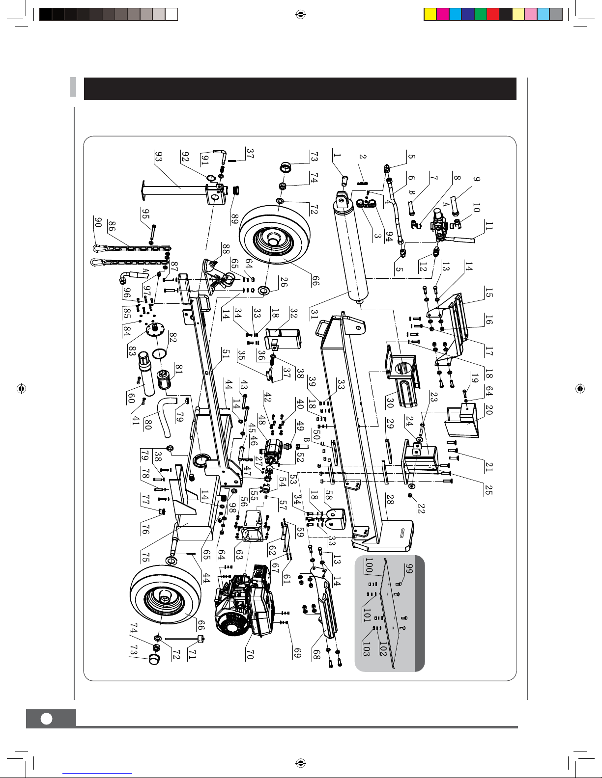
23
ILLUSTRATED PARTS LIST FOR LS301
30T LOG SPLITTER
LOG SPLITTER
24
* Parts List on page 26
PARTS DIAGRAM

LOG SPLITTER
25
PARTS LIST
No. Description
Qty
1 Pin 35
1
2 Bridge Pin
1
3 Hose Clamp 40
1
4
Hex Socket Head Cap
Screw M6x20
1
5 Right-Angle Fitting
2
6 Welded Hose
1
7 High Pressure Supply
Hose 1/2
1
8 Right-Angle Fitting 1
1
9 Low Pressure Return
Hose
1
10 Right-Angle Fitting 2
1
11 Control Valve
1
12 Straight Fitting
1
13 Bolt M12x35
8
14 Flat Washer 12
24
15 Log Cradle 1
1
16 Lock Nut M12
14
17 Bolt M10x35
4
18 Washer 10
18
19 Bolt M12x30
1
20 1-Way Wedge
1
21 Hexagon Recessed
Head Screw M12x55
6
22 Lock Nut M14
1
23 BOLT 14X90
1
24 Washer 14
4
25 Wedge
1
26 Anti-Dust Washer
2
27 Bolt M6x10
2
28 Beam Weldment
1
29 Guide Slide
2
30 Log Stripper Weldment
1
31 Cylinder
1
32 Beam Lock Bracket
1
33 Spring Washer 10
14
34 Bolt M10x25
6
35 Latch Rod
1
36 Pressure Spring
2
37 Pin 6X40
2
38 Washer 10
8
39 Nut M10
8
No. Description
Qty
40 Spring Washer 8
8
41 Bolt M8x20
6
42 Washer 8
10
43 Bolt M12x90
2
44 Cotter Pin 4x50
2
45 Beam Pivot Pin 20x110
1
46 Bridge Pin
1
47 Elastic Spider Block
1
48 Gear Pump
1
49 Outlet Connector of
Pump
1
50 Retainer Slide
2
51 Bracket Weldment
1
52 Key 3*25
1
53 Gear Pump Connector
Left
1
54 Gear Pump Connector
Right
1
55 Bolt M8x10
2
56 Bolt 5/16-24UNF
4
57 Key1/4*50
1
58 Pivot Bracket
1
59 Spring Washer 5
4
60 Manual Tube
1
61 Screw M5x10
4
62 Cover of Pump Bracket
1
63 Pump Bracket
1
64 Nut M12
5
65 Spring Washer 12
4
66 Wheel
2
67 Washer 5
4
68 Log Cradle 2
1
69 Nut M10
4
70 Engine
1
71 Dipstick
1
72 Wheel Washer 22
2
73 Dust Cap
2
74 Axle Nut M22
2
75 Tank Assembly
1
76 Washer 20
1
77 Oil Plug 20*1.5
1
78 Bolt M10x45
4
79 Clamp 25-38
2
Part Number
50001
50002
50003
50004
50005
50006
50007
50008
50009
50010
50011
50012
50013
50014
50015
50016
50017
50018
50019
50020
50021
50022
50023
50024
50025
50026
50027
50028
50029
50030
50031
50032
50033
50034
50035
50036
50037
50038
50039
Part Number
50040
50041
50042
50043
50044
50045
50046
50047
50048
50049
50050
50051
50052
50053
50054
50055
50056
50057
50058
50059
50060
50061
50062
50063
50064
50065
50066
50067
50068
50069
50070
50071
50072
50073
50074
50075
50076
50077
50078
50079

LOG SPLITTER
26
No. Description
Qty
80 Suction Hose
1
81 Return Oil Filter
1
82 O-Ring D81*3.1
1
83 Flange of Filter
1
84 Washer 6
7
85 Bolt M6x16
6
86 Safety Chain
2
87 Bolt M12x80
2
88 50mm Ball Hitch
1
89 Pipe Plug 48
1
90 Safety Clasp
1
91 Latch Rod
1
92 Circlip 34
1
93 Support Leg Weldment
1
94 Hose Clamp 45
1
95 Bolt M10x85
1
96 Washer 6
7
97 Nut M10
1
98 Flat Washer 20
1
Optional Work Table
99 Bolt M10x25
4
100 Log Table
1
101 Flat Washer 10
4
102 Spring Washer 10
4
103 Nut M10
4
Part Number
50080
50081
50082
50083
50084
50085
50086
50087
50088
50089
50090
50091
50092
50093
50094
50095
50096
50097
50098
50099
50100
50101
50102
50103

LOG SPLITTER
27
NOTES

LOG SPLITTER
28
or call 1300 363 027
for more information.
bushrangerpe.com.au
Visit
Bushranger™ is a trademark of Roy Gripske & Sons Pty Ltd. PLP shall not be liable for technical or editorial
errors or omissions contained herein, nor for incidental or consequential damages resulting from furnishing
this material. The information is provided “as is” without warranty of any kind and is subject to change
without notice. PLP also reserves the right to revise the content of this document at any time without prior
notice. No part of this document may be reproduced or transmitted in any form or by any means, electronic
or mechanical, including photocopying, recording or storing in a retrieval system, or translated into any
language form without prior written permission of PLP.
Images are for illustrative purposes only. 866.
Copyright © 2018 Roy Gripske and Sons Pty. Ltd. All rights reserved
 Loading...