

Page 1
ENGLISH
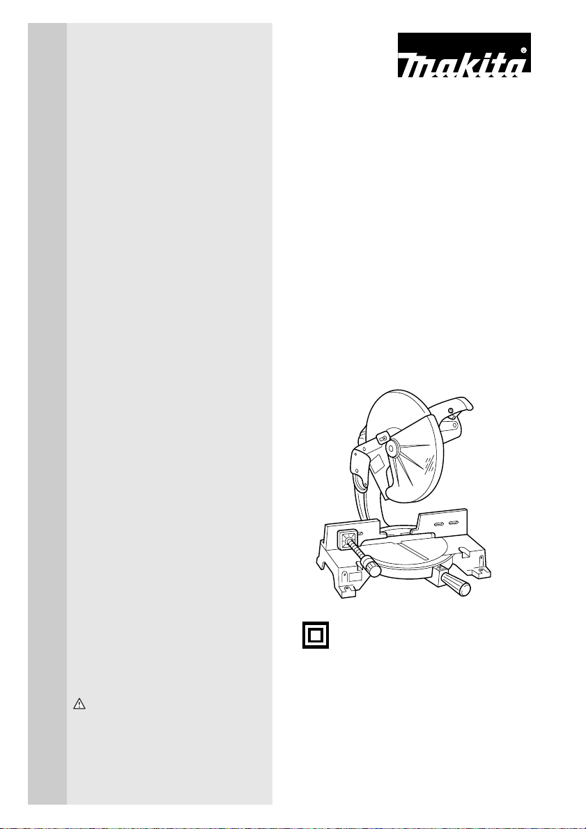
Miter Saw
MODEL LS1440
DOUBLE
INSULATION
INSTRUCTION MANUAL
WARNING:
For your personal safety, READ and UNDERSTAND before using.
SAVE THESE INSTRUCTIONS FOR FUTURE REFERENCE.
002146
Page 2

SPECIFICATIONS
Blade diameter.................................................................................................................................................... 355 mm
Hole diameter.................................................................................................................................. 25 mm and 25.4 mm
Max. Miter angle ................................................................................................................................Left 45° , Right 45°
Max. Cutting capacities (H x W)
Miter angle
0° 45° (left and right)
122 mm x 152 mm 122 mm x 115 mm
-1
No load speed (min
Dimensions (L x W x H) .....................................................................................................530 mm x 596 mm x 610 mm
Net weight............................................................................................................................................................... 34 kg
Safety class............................................................................................................................................................... /II
• Due to our continuing programme of research and development, the specifications herein are subject to change
without notice.
• Note: Specifications may differ from country to country.
SYMBOLS
The following show the symbols used for the tool. Be
sure that you understand their meaning before use.
...................Read instruction manual.
...................DOUBLE INSULATION
Intended use
The tool is intended for accurate straight and miter cutting in wood. With appropriate saw blades, aluminum
can also be sawed.
Power supply
The tool should be connected only to a power supply of
the same voltage as indicated on the nameplate, and
can only be operated on single-phase AC supply. They
are double-insulated in accordance with European
Standard and can, therefore, also be used from sockets
without earth wire.
) ............................................................................................................................................. 3,200
END201-1
2
Page 3

GENERAL SAFETY RULES GEA001-3
WARNING:
Read all instructions. Failure to follow all instructions listed below may result in
electric shock, fire and/or serious injury. The term “power tool” in all of the
warnings listed below refers to your mains-operated (corded) power tool or batteryoperated (cordless) power tool.
SAVE THESE INSTRUCTIONS
Wor k area sa fe ty
1. Keep work area clean and well lit. Cluttered and
dark areas invite accidents.
2. Do not operate power tools in explosive atmos-
pheres, such as in the presence of flammable
liquids, gases or dust. Power tools create sparks
which may ignite the dust or fumes.
3. Keep children and bystanders away while oper-
ating a power tool. Distractions can cause you to
lose control.
Electrical safety
4. Power tool plugs must match the outlet. Never
modify the plug in any way. Do not use any
adapter plugs with earthed (grounded) power
tools. Unmodified plugs and matching outlets will
reduce risk of electric shock.
5. Avoid body contact with earthed or grounded
surfaces such as pipes, radiators, ranges and
refrigerators. There is an increased risk of electric
shock if your body is earthed or grounded.
6. Do not expose power tools to rain or wet condi-
tions. Water entering a power tool will increase the
risk of electric shock.
7. Do not abuse the cord. Never use the cord for
carrying, pulling or unplugging the power tool.
Keep cord away from heat, oil, sharp edges or
moving parts. Damaged or entangled cords
increase the risk of electric shock.
8. When operating a power tool outdoors, use an
extension cord suitable for outdoor use. Use of a
cord suitable for outdoor use reduces the risk of
electric shock.
Personal safety
9. Stay alert, watch what you are doing and use
common sense when operating a power tool. Do
not use a power tool while you are tired or under
the influence of drugs, alcohol or medication. A
moment of inattention while operating power tools
may result in serious personal injury.
10. Use safety equipment. Always wear eye protection. Safety equipment such as dust mask, non-skid
safety shoes, hard hat, or hearing protection used
for appropriate conditions will reduce personal injuries.
11. Avoid accidental starting. Ensure the switch is
in the off-position before plugging in. Carrying
power tools with your finger on the switch or plugging in power tools that have the switch on invites
accidents.
12. Remove any adjusting key or wrench before
turning the power tool on. A wrench or a key left
attached to a rotating part of the power tool may
result in personal injury.
13. Do not overreach. Keep proper footing and balance at all times. This enables better control of the
power tool in unexpected situations.
14. Dress properly. Do not wear loose clothing or
jewellery. Keep your hair, clothing, and gloves
away from moving parts. Loose clothes, jewellery
or long hair can be caught in moving parts.
15. If devices are provided for the connection of
dust extraction and collection facilities, ensure
these are connected and properly used. Use of
these devices can reduce dust-related hazards.
Power tool use and care
16. Do not force the power tool. Use the correct
power tool for your application. The correct
power tool will do the job better and safer at the rate
for which it was designed.
17. Do not use the power tool if the switch does not
turn it on and off. Any power tool that cannot be
controlled with the switch is dangerous and must be
repaired.
18. Disconnect the plug from the power source and/
or the battery pack from the power tool before
making any adjustments, changing accessories,
3
Page 4

or storing power tools. Such preventive safety
measures reduce the risk of starting the power tool
accidentally.
19. Store idle power tools out of the reach of children and do not allow persons unfamiliar with
the power tool or these instructions to operate
the power tool. Power tools are dangerous in the
hands of untrained users.
20. Maintain power tools. Check for misalignment or
binding of moving parts, breakage of parts and
any other condition that may affect the power
tools operation. If damaged, have the power tool
repaired before use. Many accidents are caused
by poorly maintained power tools.
21. Keep cutting tools sharp and clean. Properly
maintained cutting tools with sharp cutting edges
are less likely to bind and are easier to control.
22. Use the power tool, accessories and tool bits
etc. in accordance with these instructions and in
the manner intended for the particular type of
power tool, taking into account the working conditions and the work to be performed. Use of the
power tool for operations different from those
intended could result in a hazardous situation.
Service
23. Have your power tool serviced by a qualified
repair person using only identical replacement
parts. This will ensure that the safety of the power
tool is maintained.
24. Follow instruction for lubricating and changing
accessories.
25. Keep handles dry, clean and free from oil and
grease.
ADDITIONAL SAFETY RULES FOR TOOL ENB040-3
1. Wear eye protection.
2. Keep hands out of path of saw blade. Avoid con-
tact with any coasting blade. It can still cause severe
injury.
3. Do not operate saw without guards in place.
Check blade guard for proper closing before
each use. Do not operate saw if blade guard
does not move freely and close instantly. Never
clamp or tie the blade guard into the open position.
4. Do not perform any operation freehand. The
workpiece must be secured firmly against the turn
base and guide fence with the vise during all operations. Never use your hand to secure the workpiece.
5. Never reach around saw blade.
6. Turn off tool and wait for saw blade to stop
before moving workpiece or changing settings.
7. Unplug tool before changing blade or servicing.
8. Don’t use the tool in the presence of flammable liq-
uids or gases.
9. Check the blade carefully for cracks or damage
before operation.
Replace cracked or damaged blade immediately.
10. Use only flanges specified for this tool.
11. Be careful not to damage the arbor, flanges (espe-
cially the installing surface) or bolt. Damage to
these parts could result in blade breakage.
12. Make sure that the turn base is properly secured so
it will not move during operation.
13. For your safety, remove the chips, small pieces, etc.
from the table top before operation.
14. Avoid cutting nails. Inspect for and remove all nails
from the workpiece before operation.
15. Make sure the shaft lock is released before the
switch is turned on.
16. Be sure that the blade does not contact the turn
base in the lowest position.
17. Hold the handle firmly. Be aware that the saw
moves up or down slightly during start-up and stopping.
18. Make sure the blade is not contacting the workpiece
before the switch is turned on.
19. Before using the tool on an actual workpiece, let it
run for a while. Watch for vibration or wobbling that
could indicate poor installation or a poorly balanced
blade.
20. Wait until the blade attains full speed before cutting.
21. Stop operation immediately if you notice anything
abnormal.
22. Do not attempt to lock the trigger in the on position.
23. Be alert at all times, especially during repetitive,
monotonous operations. Don't be lulled into a false
sense of security. Blades are extremely unforgiving.
24. Always use accessories recommended in this manual. Use of improper accessories such as abrasive
wheels may cause an injury.
25. Do not use the saw to cut other than aluminum,
wood or similar materials.
26. Connect miter saws to a dust collecting device
when sawing.
4
Page 5

27. Select saw blades in relation to the material to
be cut.
28. Take care when slotting.
29. Replace the kerf board when worn.
30. Do not use saw blades manufactured from high
speed steel.
31. Some dust created from operation contains
chemicals known to cause cancer, birth defects
or other reproductive harm. Some examples of
these chemicals are:
• lead from lead-based-painted material
• arsenic and chromium from chemically-
treated lumber.
Your risk from these exposures varies, depending on how often you do this type of work. To
SAVE THESE INSTRUCTIONS
reduce your exposure to these chemicals: work
in a well ventilated area and work with approved
safety equipment, such as those dust masks
that are specially designed to filter out microscopic particles.
32. To reduce the emitted noise, always be sure that
the blade is sharp and clean.
33. The operator is adequately trained in the use,
adjustment and operation of the machine.
34. Use correctly sharpened saw blades. Observe
the maximum speed marked on the saw blade.
35. Refrain from removing any cut-offs or other
parts of the workpiece from the cutting area
whilst the machine is running and the saw head
is not in the rest position.
5
Page 6
INSTALLATION
1
1. Handle latch
1
1. Bolt
Bench mounting
002147
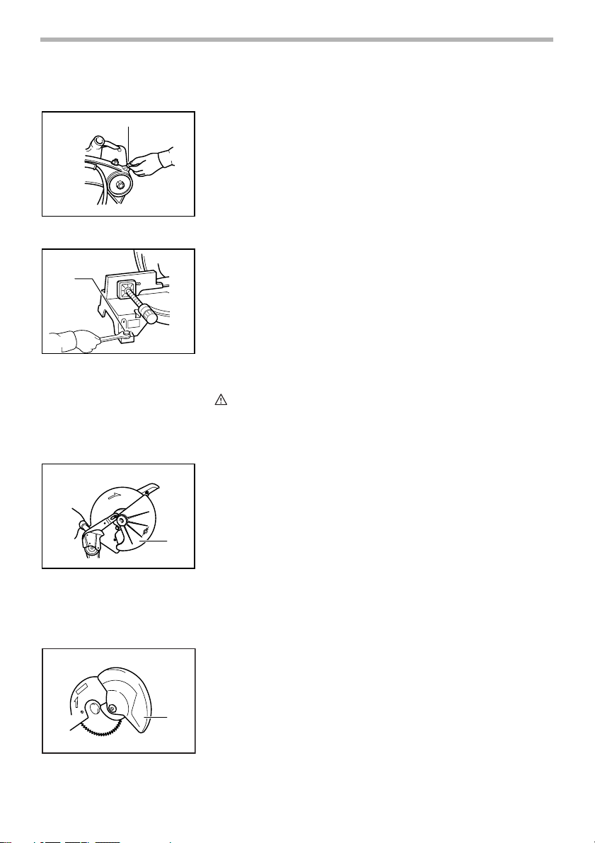
When the tool is shipped, the handle is locked in the lowered position by the
handle latch. Release the handle latch by lowering the handle slightly and turn
the handle latch to the released position.
003638
This tool should be bolted with four bolts to a level and stable surface using the
bolt holes provided in the tool’s base. This will help prevent tipping and possible injury.
FUNCTIONAL
DESCRIPTION
1. Blade guard
1. Blade guard
6
002149
1
001782
1
CAUTION:
• Always be sure that the tool is switched off and unplugged before
adjusting or checking function on the tool.
Blade guard
When lowering the handle, the blade guard rises automatically. The guard is
spring loaded so it returns to its original position when the cut is completed
and the handle is raised. NEVER DEFEAT OR REMOVE THE BLADE GUARD
OR THE SPRING WHICH ATTACHES TO THE GUARD.
In the interest of your personal safety, always maintain the blade guard in good
condition. Any irregular operation of the blade guard should be corrected
immediately. Check to assure spring loaded return action of guard. NEVER
USE THE TOOL IF THE BLADE GUARD OR SPRING ARE DAMAGED,
FAULTY OR REMOVED. DOING SO IS HIGHLY DANGEROUS AND CAN
CAUSE SERIOUS PERSONAL INJURY.
If the see-through blade guard becomes dirty, or sawdust adheres to it in such
a way that the blade is no longer easily visible, unplug the saw and clean the
guard carefully with a damp cloth. Do not use solvents or any petroleum-based
cleaners on the plastic guard.
If the blade guard is especially dirty and vision through the guard is impaired,
use the supplied socket wrench to loosen the hex bolt holding the center cover.
Loosen the hex bolt by turning it counterclockwise and raise the blade guard
and center cover. With the blade guard so positioned, cleaning can be more
completely and efficiently accomplished. When cleaning is complete, reverse
procedure above and secure bolt. Do not remove spring holding blade guard.
If guard becomes discolored through age or UV light exposure, contact a Makita service center for a new guard. DO NOT DEFEAT OR REMOVE GUARD.
Page 7
002150
Kerf board
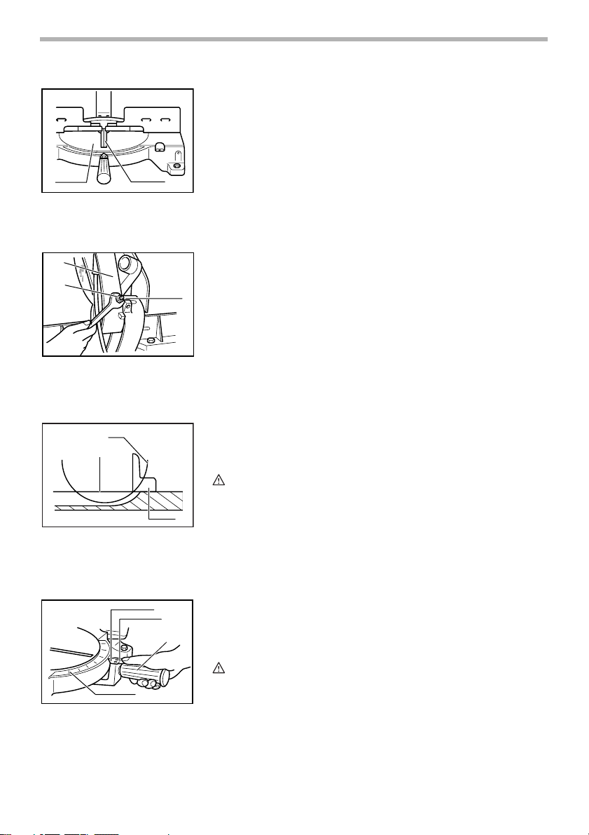
This tool is provided with the kerf board in the turn base to minimize tearing on
the exit side of a cut. If the kerf groove has not yet been cut in the kerf board by
the factory, you should cut the groove before actually using the tool to cut a
workpiece. Switch on the tool and lower the blade gently to cut a groove in the
kerf board.
1
1. Turn base
2. Kerf board
1
2
1. Gear housing
2. Hex nut
3. Adjusting bolt
2
1
1. Top surface of turn base
2. Periphery of blade
3. Guide fence
2
002151
001540
Maintaining maximum cutting capacity
This tool is factory adjusted to provide the maximum cutting capacity for a 355
mm saw blade.
When installing a new blade, always check the lower limit position of the blade
3
and if necessary, adjust it as follows:
First, unplug the tool. Lower the handle completely. Loosen the hex nut at the
rear of the gear housing. Use a screwdriver to turn the adjusting bolt until the
periphery of the blade extends slightly below the top surface of the turn base
at the point where the front face of the guide fence meets the top surface of the
turn base.
With the tool unplugged, rotate the blade by hand while holding the handle all
the way down to be sure that the blade does not contact any part of the lower
base. Re-adjust slightly, if necessary.
After adjusting, tighten the hex nut with the wrench while carefully holding the
adjusting bolt in position with the screwdriver.
At this time, make sure that the handle can be locked in the lowered position
by turning the handle latch. If the handle cannot be locked so, turn the adjusting bolt so that the handle can be locked in the lowered position.
CAUTION:
• After installing a new blade, always be sure that the blade does not
3
contact any part of the lower base when the handle is lowered
completely. Always do this with the tool unplugged.
1. Pointer
2. Lock lever
3. Miter scale
4. Grip
002152
1
2
Adjusting the miter angle
Loosen the grip by turning counterclockwise. Turn the turn base while pressing
down the lock lever. When you have moved the grip to the position where the
pointer points to the desired angle on the miter scale, securely tighten the grip
4
clockwise.
CAUTION:
3
• When turning the turn base, be sure to raise the handle fully.
• After changing the miter angle, always secure the turn base by tightening
the grip firmly.
7
Page 8
1. Switch trigger
Fence plate
The fence plate is designed to prevent smaller cutting scraps from jamming
inside the blade case. The fence plate moves right or left automatically as the
turn base is rotated.
003639
Switch action
CAUTION:
• Before plugging in the tool, always check to see that the switch trigger
actuates properly and returns to the “OFF” position when released.
To start the tool, simply pull the switch trigger. Release the switch trigger to
stop.
1
WAR NING:
• NEVER use tool without a fully operative switch trigger. Any tool with an
inoperative switch is HIGHLY DANGEROUS and must be repaired before
further usage.
ASSEMBLY
1. Socket wrench
CAUTION:
• Always be sure that the tool is switched off and unplugged before
carrying out any work on the tool.
Installing or removing saw blade
CAUTION:
• Always be sure that the tool is switched off and unplugged before
installing or removing the blade.
• Use only the Makita socket wrench provided to install or remove the
blade. Failure to do so may result in overtightening or insufficient
tightening of the hex bolt. This could cause an injury.
002155
To remove the blade, use the socket wrench to loosen the hex bolt holding the
center cover by turning it counterclockwise. Raise the blade guard and center
cover.
1
8
Page 9
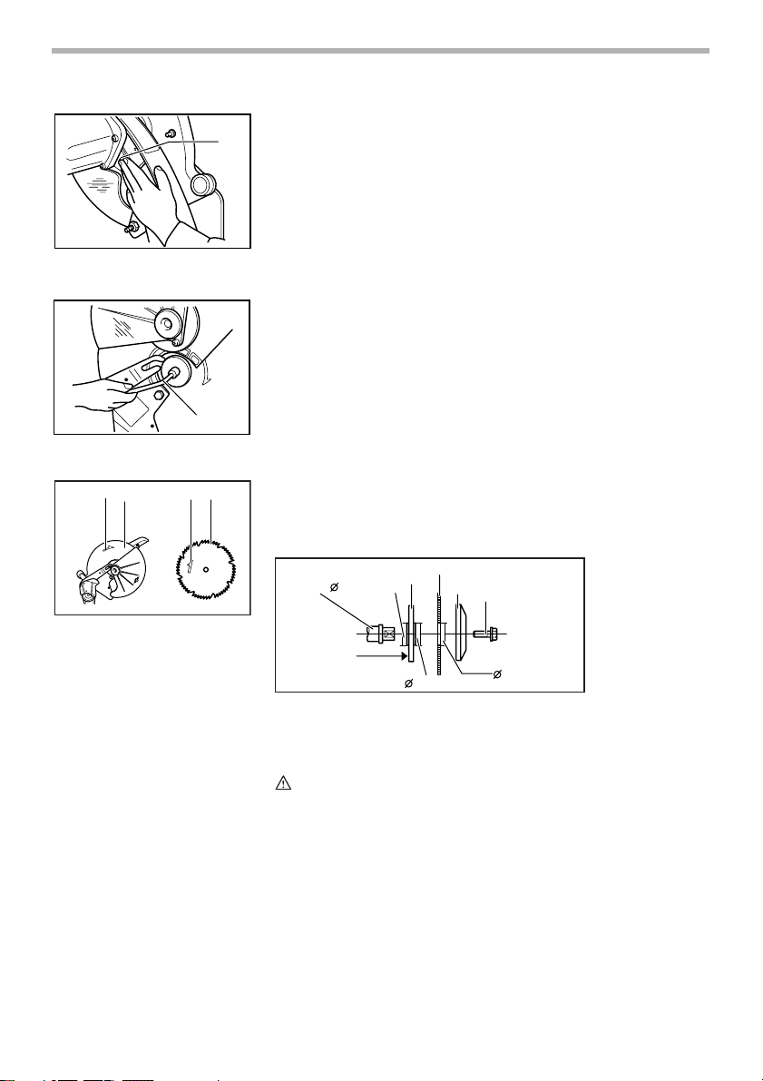
1. Shaft lock
1. Socket wrench
2
1 4 3
1. Blade case
2. Arrow
3. Saw blade
4. Arrow
Press the shaft lock to lock the spindle and use the socket wrench to loosen
002156
the hex bolt counterclockwise. Then remove the hex bolt, outer flange and
blade.
1
002243
1
002860
To install the blade, mount it carefully onto the spindle, making sure that the
direction of the arrow on the surface of the blade matches the direction of the
arrow on the blade case. Install the outer flange and hex bolt, and then use the
socket wrench to tighten the hex bolt securely clockwise while pressing the
shaft lock.
1
25.4mm
3
2
4
5
002154
6
25mm
1. Spindle 2. Inner flange
3. Blade 4. Outer flange
5. Hex bolt 6. 25.4mm marking
25mm
CAUTION:
• The inner flange has a 25 mm diameter on one side and a 25.4 mm
diameter on the other. The side with 25.4 mm diameter is marked by
“25.4”. Use the correct side for the hole diameter of the blade you intend
to use. Mounting the blade on the wrong side can result in dangerous
vibration.
9
Page 10
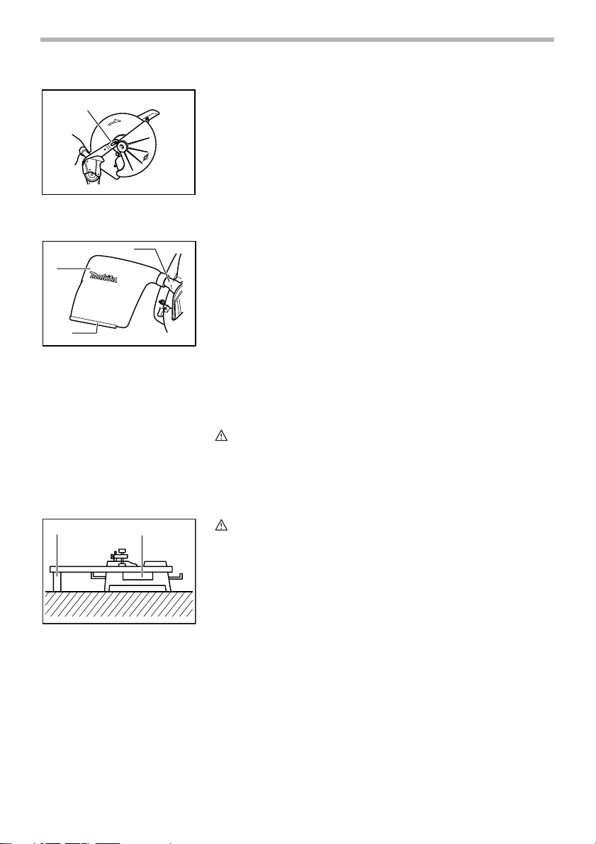
1
1. Pin
2
3
1. Dust nozzle
2. Dust bug
3. Fastener
1
Slip the pin on the blade guard into the slot in the guide arm while returning the
002264
blade guard to its original fully closed position. Then tighten the hex bolt clockwise to secure the center cover. Lower the handle to make sure that the blade
guard moves properly. Make sure shaft lock has released spindle before making cut.
002157
1
Dust bag
The use of the dust bag makes cutting operations clean and dust collection
easy. To attach the dust bag, fit it onto the dust nozzle.
When the dust bag is about half full, remove the dust bag from the tool and pull
the fastener out. Empty the dust bag of its contents, tapping it lightly so as to
remove particles adhering to the insides which might hamper further collection.
NOTE:
If you connect a Makita vacuum cleaner to your saw, more efficient and
cleaner operations can be performed.
Securing workpiece
WAR NING:
• It is extremely important to always secure the workpiece properly and
tightly with the vise. Failure to do so can cause the tool to be damaged
and/or the workpiece to be destroyed. PERSONAL INJURY MAY ALSO
RESULT. Also, after a cutting operation, DO NOT raise the blade until the
blade has come to a complete stop.
001549
2
CAUTION:
• When cutting long workpieces, use supports that are as high as the top
surface level of the turn base. Do not rely solely on the vertical vise and/
or horizontal vise to secure the workpiece.
Thin material tends to sag. Support workpiece over its entire length to
avoid blade pinch and possible KICKBACK.
1. Suppor t
2. Turn base
10
Page 11
1
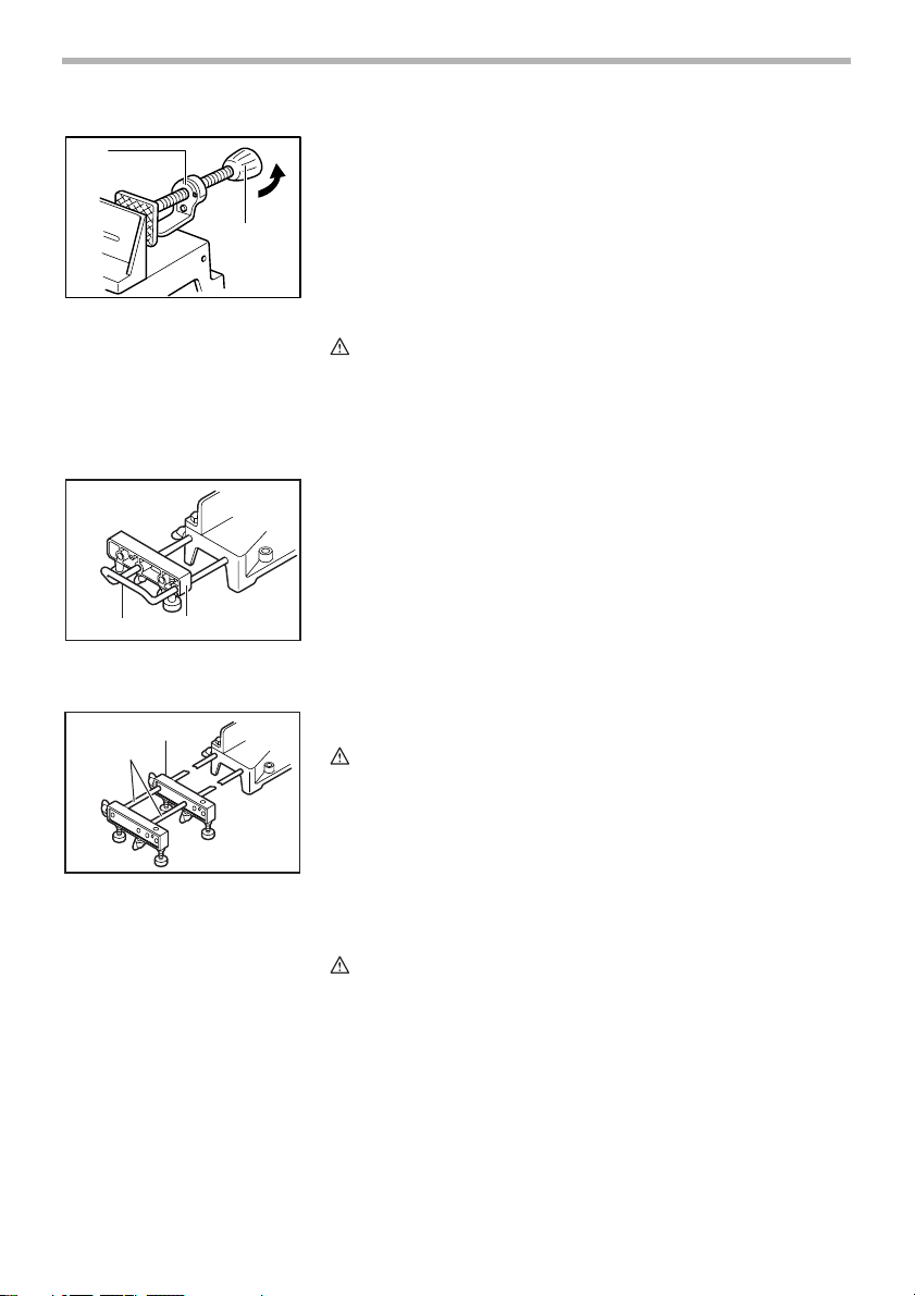
1. Projection
2. Vise knob
12
1. Holder
2. Holder assembly
1
2
002158
Horizontal vise (Accessory)
The horizontal vise can be installed on either the left or right side of the base.
When performing 15° or greater miter cuts, install the horizontal vise on the
side opposite the direction in which the turn base is to be turned. By turning
the vise knob counterclockwise, the screw is released and the vise shaft can
2
be moved rapidly in and out. By turning the vise knob clockwise, the screw
remains secured. To grip the workpiece, turn the vise knob gently clockwise
until the projection reaches its topmost position, then fasten securely. If the
vise knob is forced in or pulled out while being turned clockwise, the projection
may stop at an angle. In this case, turn the vise knob back counterclockwise
until the screw is released, before turning again gently clockwise.
CAUTION:
• Grip the workpiece only when the projection is at the topmost position.
Failure to do so may result in insufficient securing of the workpiece. This
could cause the workpiece to be thrown, cause damage to the blade or
cause the loss of control, which can result in PERSONAL INJURY.
001809
Holders and holder assembly (optional accessories)
The holders and the holder assembly can be installed on either side as a convenient means of supporting workpieces horizontally. Install them as shown in
the figure. Then tighten the screws firmly to secure the holders and the holder
assembly.
When cutting long workpieces, use the holder-rod assembly (optional acces-
001810
sory). It consists of two holder assemblies and two rods 12.
CAUTION:
• Always support long workpieces level with the top surface of the turn
base for accurate cuts and to prevent dangerous loss of control of the
tool.
1. Holder assembly
2. Rod 12
OPERATION
CAUTION:
• Before use, be sure to release the handle from the lowered position by
turning the handle latch to the released position.
• Make sure the blade is not contacting the workpiece, etc. before the
switch is turned on.
• Do not apply excessive pressure on the handle when cutting. Too much
force may result in overload of the motor and/or decreased cutting
efficiency. Push down handle with only as much force as is necessary for
smooth cutting and without significant decrease in blade speed.
• Gently press down the handle to perform the cut. If the handle is pressed
down with force or if lateral force is applied, the blade will vibrate and
11
Page 12
002159
leave a mark (saw mark) in the workpiece and the precision of the cut will
be impaired.
1. Press cutting
Secure the workpiece with the vise. Switch on the tool without the blade
making any contact and wait until the blade attains full speed before lowering. Then gently lower the handle to the fully lowered position to cut the
workpiece. When the cut is completed, switch off the tool and WAIT
UNTIL THE BLADE HAS COME TO A COMPLETE STOP before returning the blade to its fully elevated position.
2. Miter cutting
Refer to the previously covered “Adjusting the miter angle”.
1
2
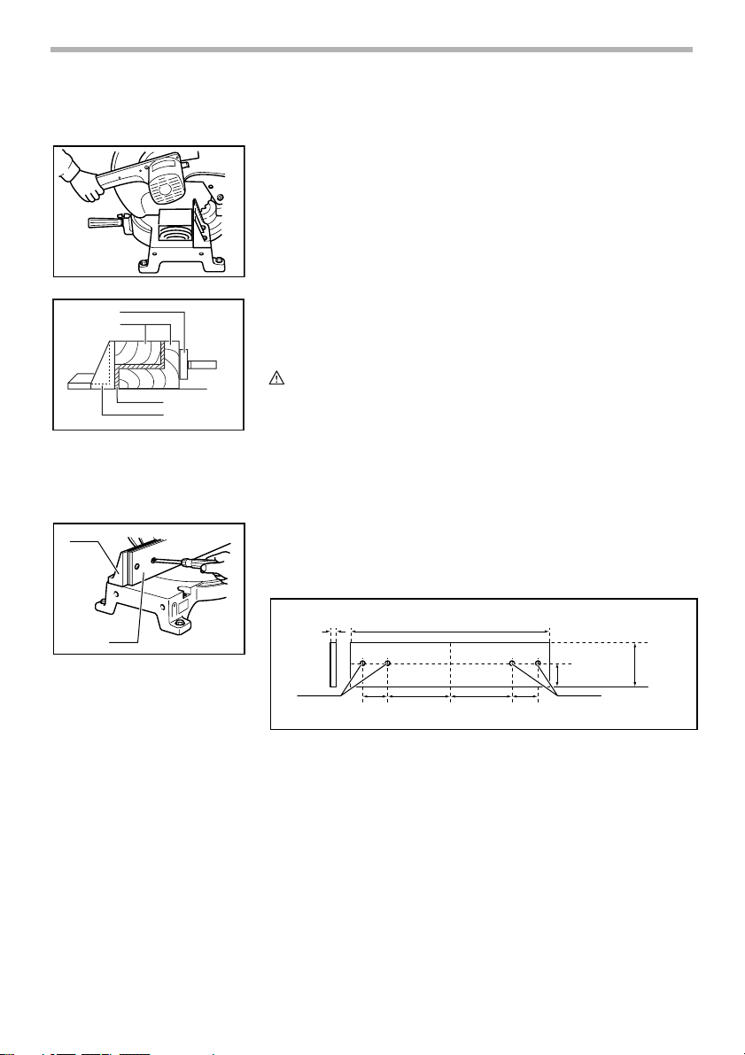
1. Horizontal vise
2. Spacer block
3. Aluminum extrusion
4. Guide fence
1
2
1. Guide fence
2. Wood facing
002861
3. Cutting aluminum extrusion
When securing aluminum extrusions, use spacer blocks or pieces of
scrap as shown in the figure to prevent deformation of the aluminum. Use
a cutting lubricant when cutting the aluminum extrusion to prevent buildup of the aluminum material on the blade.
CAUTION:
3
4
002160
• Never attempt to cut thick or round aluminum extrusions. Thick aluminum
extrusions may come loose during operation and round aluminum
extrusions cannot be secured firmly with this tool.
4. Wood facing
Use of wood facing helps to assure splinter-free cuts in workpieces.
Attach a wood facing to the guide fence using the holes in the guide
fence.
See the figure concerning the dimensions for a suggested wood facing.
004856
10mm
64mm
154mm
Over 480mm
154mm
64mm
45mm
90mm
11
1. Hole
12
Page 13
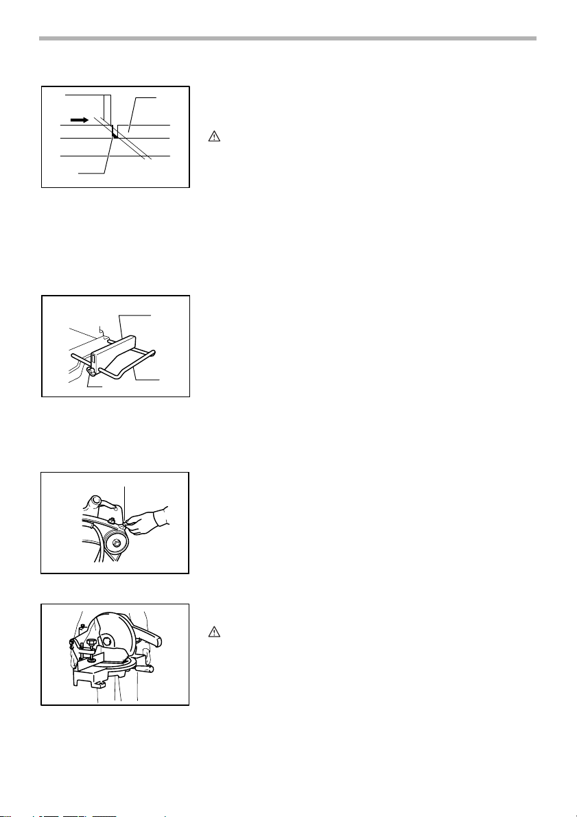
003640
1
2
3
4
5
1. Blade
2. Wood facing
3. Wood facing
4. Workpiece
5. There should be no gap between
the blade, the wood facing and the
workpiece
001846
1
3
2
1. Set plate
2. Holder
3. Screw
002147
1
After changing the miter angle, cut the wood facing at that selected
angle. If there is a gap between the blade, the wood facing and the workpiece, move the wood facing slightly in the direction of the arrow and cut
it again.
CAUTION:
• Use straight wood of even thickness as the wood facing.
• Use screws to attach the wood facing to the guide fence. The screws
should be installed so that the screw heads are below the surface of the
wood facing.
• When the wood facing is attached, do not turn the turn base with the
handle lowered. The blade and/or the wood facing will be damaged.
NOTE:
• When the wood facing is attached, the maximum cutting capacities in
width will be reduced by thickness of the wood facing.
5. Cutting repetitive lengths
When cutting several pieces of stock to the same length, ranging from
300 mm to 400 mm, use of the set plate (optional accessory) will facilitate more efficient operation. Install the set plate on the holder (optional
accessory) as shown in the figure.
Align the cutting line on your workpiece with either the left or right side of
the groove in the kerf board, and while holding the workpiece from moving, move the set plate flush against the end of the workpiece. Then
secure the set plate with the screw. When the set plate is not used,
loosen the screw and turn the set plate out of the way.
NOTE:
• Use of the holder-rod assembly (optional accessory) allows cutting
repetitive lengths up to 2,200 mm approximately.
Carrying tool
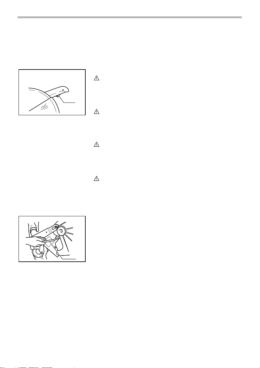
Make sure that the tool is unplugged. Secure the turn base at right miter angle
fully by means of the grip. Lower the handle fully and lock it in the lowered
position by turning the handle latch to the locked position.
1. Handle latch
002263
Carry the tool by holding both sides of the tool base as shown in the figure. If
you remove the holders, dust bag, etc., you can carry the tool more easily.
CAUTION:
• Always secure all moving portions before carrying the tool.
• Handle latch is for carrying and storage purposes only and not for any
cutting operations.
13
Page 14
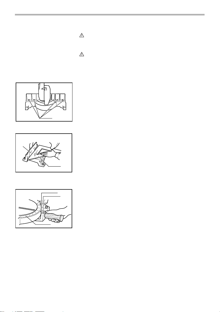
MAINTENANCE
1
1. Hex bolt
1
1. Guide fence
2. Triangular rule
2
1
2
CAUTION:
• Always be sure that the tool is switched off and unplugged before
attempting to perform inspection or maintenance.
WAR NING:
• Always be sure that the blade is sharp and clean for the best and safest
performance.
Adjusting the cutting angle
This tool is carefully adjusted and aligned at the factory, but rough handling
002162
may have affected the alignment. If your tool is not aligned properly, perform
the following:
Loosen the grip which secures the turn base. Turn the turn base so that
the pointer points to 0° on the miter scale. Then turn the turn base
slightly clockwise and counterclockwise to seat the turn base in the 0°
miter notch. (Leave as it is if the pointer does not point to 0°.) Loosen the
hex bolts securing the guide fence using the socket wrench.
002163
002265
Lower the handle fully and lock it in the lowered position by turning the
handle latch to the locked position. Square the side of the blade with the
face of the guide fence using a triangular rule, try-square, etc. Then
securely tighten the hex bolts on the guide fence in the order from the
right side.
Make sure that the pointer on the indication plate points to 0° on the
miter scale. If the pointer does not point to 0°, loosen the screws which
secure the indication plate and adjust it so that the pointer will point to 0°.
1. Pointer
2. Screws
3. Miter scale
14
3
Page 15
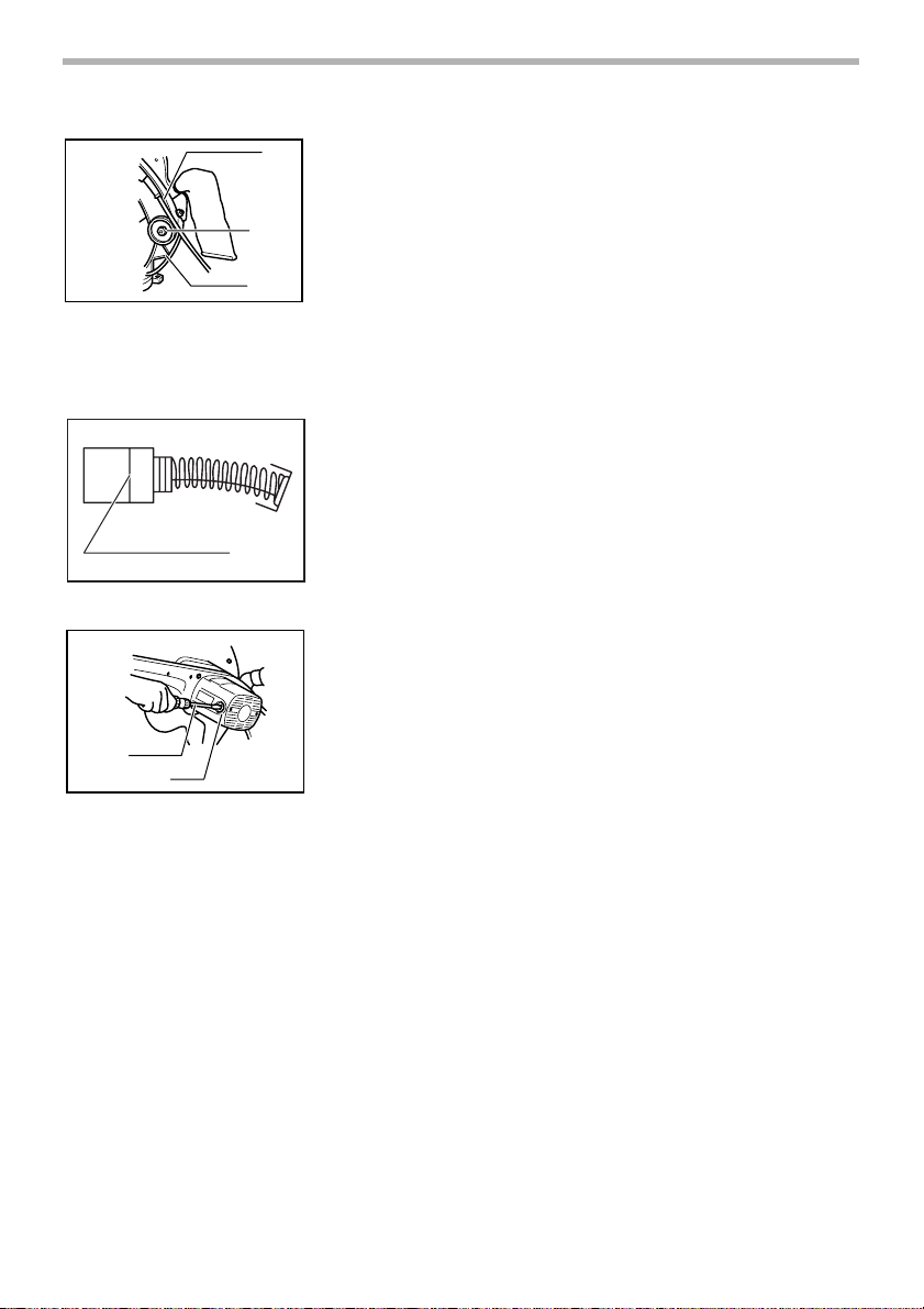
1. Gear housing
2. Hex lock nut
3. Arm
1. Limit mark
1
2
1. Screwdriver
2. Brush holder cap
002161
Adjusting for smooth handle action
1
The hex lock nut which holds the gear housing and the arm has been factory
adjusted to assure smooth handle action up and down and to guarantee precise cutting. Do not tamper with it. Should looseness develop at the gear housing and arm connection, perform the following adjustment. Work the handle up
2
3
1
and down while tightening the hex lock nut; the best position to tighten the hex
lock nut is just before the motor body weight is obvious.
After adjusting the hex lock nut, be sure that the handle returns automatically
to the initial, raised position from any position. If the hex lock nut is too loose,
the cutting accuracy will be affected; if it is too tight, it will be hard to work the
handle up and down. Note that this is a self locking nut. It is a special type that
does not loosen in normal use. It should not be overtightened or replaced with
other types of nuts.
001145
Replacing carbon brushes
Remove and check the carbon brushes regularly. Replace when they wear
down to the limit mark. Keep the carbon brushes clean and free to slip in the
holders. Both carbon brushes should be replaced at the same time. Use only
identical carbon brushes.
Use a screwdriver to remove the brush holder caps. Take out the worn carbon
002164
brushes, insert the new ones and secure the brush holder caps.
After use
• After use, wipe off chips and dust adhering to the tool with a cloth or the
like. Keep the blade guard clean according to the directions in the
previously covered “Blade guard”. Lubricate the sliding portions with tool
oil to prevent rust.
To maintain product SAFETY and RELIABILITY, repairs, any other maintenance or adjustment should be performed by Makita Authorized Service Centers, always using Makita replacement parts.
15
Page 16

ACCESSORIES
CAUTION:
• These accessories or attachments are recommended for use with your Makita tool specified in this manual. The
use of any other accessories or attachments might present a risk of injury to persons. Only use accessory or
attachment for its stated purpose.
If you need any assistance for more details regarding these accessories, ask your local Makita service center.
• Carbide-tipped saw blades
• Socket wrench 13
• Holder set
• Holder rod assembly
• Set plate
• Dust bag
• Triangular rule
16
Page 17

Memo
17
Page 18

Memo
18
Page 19

Memo
19
Page 20

883619D8
Makita Corporation
 Loading...