

Page 1
Model: 205105/205106
Lit. #: 98-1342/12-08
A
Page 2

Page 3

CONTENTS
English
Français
Español
Deutsch
Italiano
Português
2 - 14
15 - 28
29 - 42
43 - 56
57 - 70
71 - 84
1
Page 4
Congratulations on your purchase of the Bushnell® Pro™ 1600 Laser Rangefinder, our top of the line laser
rangefinder for golfers and used by more golf professionals than any other brand. The Pro™ 1600 is a precision
Laser Rangefinding optical instrument designed to provide many years of enjoyment. This booklet will help you
achieve optimum performance by explaining its adjustments and features as well as how to care for this precise laser
rangefinding optical instrument. To ensure optimal performance and longevity, please read these instructions before
using your Pro™ 1600.
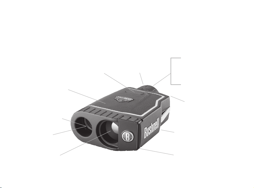
Rubber Armored &
100% Waterproof
Construction
Objective and
Laser Transmit
Lens with
RainGuard
Coating
2
®
HD
Power
+/-2 Diopter
Adjustment
Twist-Up Eyepiece
with RainGuard
®
In-View Display
Mode Button
Tripod Mount
Battery CompartmentLaser Receiver
HD
Page 5

INTRODUCTION
Your Bushnell® Pro
range readings from 5-1600 yards / 5-1463meters. Measuring 1.7 x 5.1 x 3.7 inches, the 12-ounce Pro
superb and accurate range performance to +/- one yard. The Pro
™
1600 is an advanced premium laser rangefinder comprised of Digital Technology allowing
™
1600 features Selective Targeting™ Modes, Superb
™
1600 delivers
Optical Quality, 100% Waterproof Construction, and Bushnell’s RainGuard® HD coating.
HOW OUR DIGITAL TECHNOLOGY WORKS
The Pro
™
1600 emits invisible, eye safe, infrared energy pulses. The Pro
™
1600’s Advanced Digital microprocessor
and ASIC chip (Application-Specific Integrated Circuit) results in instantaneous and accurate readings every time.
Sophisticated digital technology instantaneously calculates distances by measuring the time it takes for each pulse to
travel from the rangefinder, to the target, and back.
RANGING ACCURACY
The ranging accuracy of the Pro
™
1600 is plus or minus one yard / meter under most circumstances. The maximum
range of the instrument depends on the reflectivity of the target. The maximum distance for most objects is 1000
yards / 914 meters while for highly reflective objects the maximum is 1600 yards / 1463 meters. Note: You will get
both longer and shorter maximum distances depending on the reflective properties of the particular target and the
environmental conditions at the time the distance of an object is being measured.
The color, surface finish, size and shape of the target all affect reflectivity and range. The brighter the color, the
longer the range. Red is highly reflective, for example, and allows longer ranges than the color black, which is the
least reflective color. A shiny finish provides more range than a dull one. A small target is more difficult to range than
a larger target. The angle to the target also has an effect. Shooting to a target at a 90 degree angle (where the target
surface is perpendicular to the flight path of the emitted energy pulses) provides good range while a steep angle on
the other hand, provides limited ranging. In addition, lighting conditions (e.g. the amount of sunlight) will affect
3
Page 6
the ranging capabilities of the unit. The less light (e.g. overcast skies) the farther the unit’s maximum range will be.
Conversely, very sunny days will decrease the unit’s maximum range.
GETTING STARTED
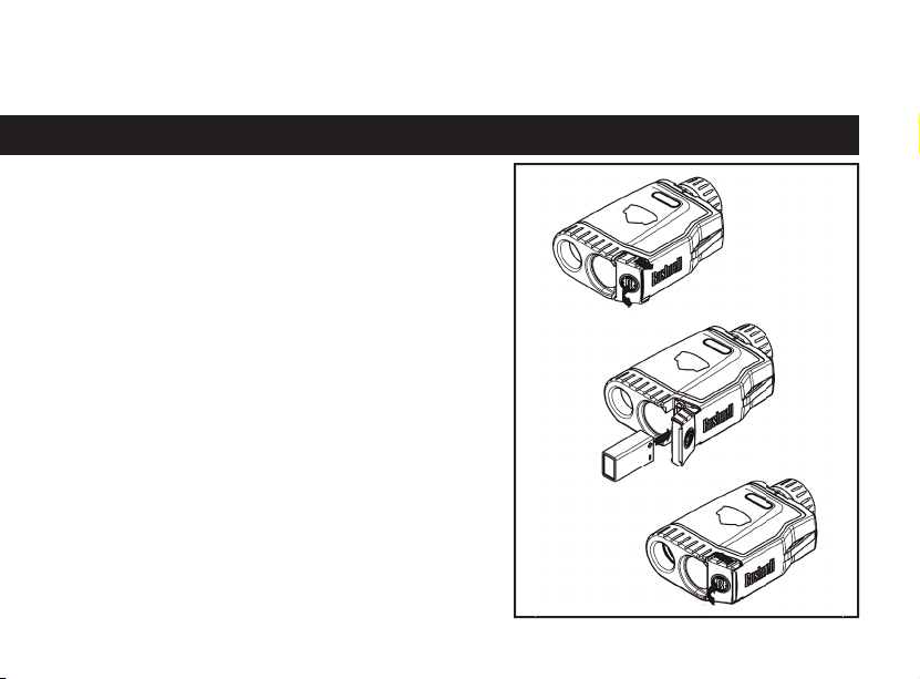
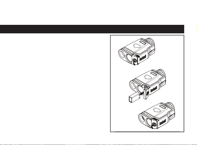
INSERTING THE BATTERY
First slide the door toward outside. The hinged door can now
be opened. Insert one 9-volt alkaline battery into the slot as
indicated, then close the battery door and slide until it locks
in to place. The battery slot was designed to only accept the
battery in the correct position. Therefore, if you are not able to
close the batter door, check to ensure that the battery has been
installed correctly.
NOTE: Use only high quality alkaline batteries. Do not use
heavy duty or lithium batteries. It is recommended that the
battery be replaced at least once every 12 months.
Low Battery Indicator: If the Y (Yards) or M (Meters) indicator
blinks continuously or “loB” is displayed within the In-view
readout, the battery charge is getting low and the 9-volt alkaline
battery should be replaced.
ADJUSTING THE EYEPIECE
Your Pro
™
1600 is constructed with a twist-up eyepiece
designed for comfort and to exclude extraneous light. For users
4
Page 7

without eyeglasses, rotate the eyecup counter clockwise while pulling up until it locks into the fully “up” position. The
™
Pro
1600 provides extra long eye-relief. If you wear glasses, make sure the eyecup is in the down position as this will
bring your eye closer the eyepiece lens allowing you to see a full field of view. To lower the eyecup from the full “up”
position, rotate clockwise while pushing down slightly. It is also possible to set the eyecup to positions “in between”,
fully up and full down, which may suit some individuals better.
The Pro
1600 is also equipped with an adjustable eyepiece (+/- 2 Diopter Adjustment) that allows one to focus the
™
LCD display relative to the image. Simply rotate the diopter setting until the LCD is in focus.
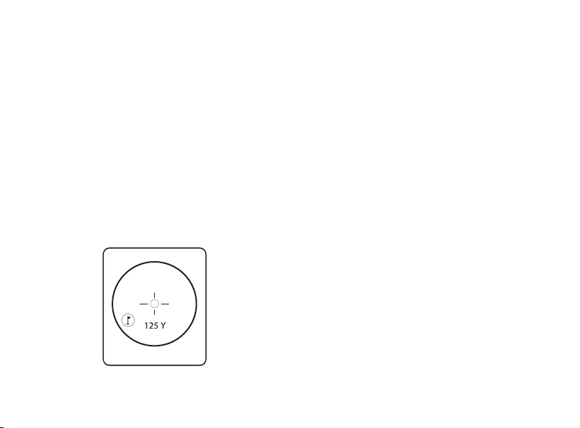
OPERATIONAL SUMMARY
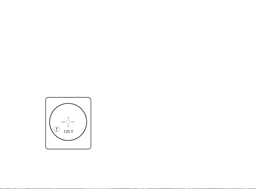
While looking through the 7x eyepiece, depress the power button once to activate the in-view Liquid Crystal
Display (LCD). Place the aiming circle (located in the center of the field of view) upon a target at least 5 yards away,
depress and hold the power button down until the range reading is displayed near the bottom of the in-view display.
Crosshairs surrounding the aiming circle indicate that the laser is being transmitted. Once a range has been acquired,
you can release the power button. The crosshairs surrounding the aiming circle will disappear once the power button
has been released (i.e. the laser is no longer being transmitted). Note: Once activated, the Pro
™
1600’s LCD will
remain active and display the last distance measurement for 30 seconds. You can depress the power button again at
any time to distance to a new target. As with any laser device, it is not recommended to directly view the emissions
for long periods of time with magnified lenses. The maximum time the laser is transmitted (fired) is 10 seconds. To
re-fire, press the button down again.
LIQUID CRYSTAL DISPLAY (LCD) INDICATORS
Your Pro
™
1600’s LCD incorporates illuminated indicators that advise the user unit of measure, when
the laser is actively firing, when a target has been acquired, and targeting modes. A summary of these features is
presented below:
5
Page 8

UNIT OF MEASURE OPTIONS
The Pro
1600 can be used to measure distances in yards or meters. The unit of measure indicators are located in the
™
lower right portion of the LCD. To select between yards and meters, quickly press and release the POWER button
to turn on the unit (on top of the unit), look through the eyepiece, depress the “MODE” button (left side of the
eyepiece) and hold it down for approximately 5 seconds. If you are changing from yards to meters, a change in unit
of measure will be indicated by the illumination of the M for meter indicator while the Y for Yard indicator is turned
off. If you are changing from meters to yards, the opposite will occur. The Pro
™
1600 will return to the last unit of
measure setting used each time the unit is turned on.
ACTIVE LASER
Crosshairs surrounding the aiming circle indicate that the laser is being transmitted. Once a range has been acquired,
you can release the power button. The crosshairs surrounding the circle will disappear once the power button has been
released (i.e. the laser is no longer being transmitted).
SELECTIVE TARGETING™ MODES
The Pro
1600 was especially designed with golfers in mind. The selective targeting modes allow you to adjust the
™
performance parameters of the unit to suit your specific situation and environment. To move from one mode to
another, press the POWER button once to turn on the unit. While looking through the eyepiece, press the MODE
button and quickly release. The different targeting modes available and mode indicators are listed below:
PinSeeker (LCD Indicator - ) Ever have trouble getting distance to the flag? This advanced mode allows easy
acquisition of the flag without inadvertently getting distances to background targets (i.e. trees) that have stronger
signal strength.
6
Page 9
Once in this mode, press the POWER button to turn the unit on. Next, align the aiming circle reticle onto the flag
that you want distance to. Next, press and hold the POWER button and move the laser slowly over the flag or desired
object until a circle surrounds the flag indicator. If the laser beam recognized more than one object (i.e. flag and
background trees), distance of the flag will be displayed and a circle will surround the PinSeeker indicator informing
the user that distance to the flag (i.e. closer object) is being displayed in the LCD (as seen below). There may be times
when only the laser beam only sees one object in its path. In this case, the distance will be displayed, but because more
than one object was not acquired, a circle will not surround the flag indicator.
TIP: While pressing the POWER button, you can move the device slowly from object to object and intentionally
force the laser to hit multiple objects to ensure that you are only displaying the closest of the objects recognized by
the laser.
Once the device has shut off, the unit will always default back to the last mode used.
7
Page 10
PinSeeker with Slope +/-™ (LCD Indicator - ˚ ) This advanced mode will be found only on model 20-5106
™
(Pro
1600 with Slope +/-™). Model 20-5106 features a built-in accelerometer-based inclinometer that digitally
displays the exact slope angle from -20 to +20 degrees of elevation and is +/- 1.0 degree accurate. The Slope +/-™
mode will automatically compute an angle compensated range based upon distance and slope angle determined by
the laser rangefinder and built-in inclinometer. This data is then combined with internal algorithmic formulas dealing
with average club use and ball trajectories. The angle compensated range provides direction on how to play the shot
(i.e. add distance if an incline, subtract distance if a decline).
How to use Slope +/-™
Once in this mode, you will see a “ ° ” in the field of view informing you that you are in the Slope +/- Mode. Press
the POWER button to obtain distance to the flag or other objects. Once the range is displayed, continue to hold the
POWER button down for approximately 2 seconds while holding the aiming circle on the flag and keeping the unit
as steady as possible so as to allow the inclinometer enough time to measure slope. Then release the POWER button.
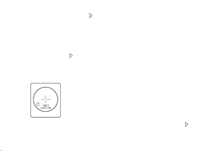
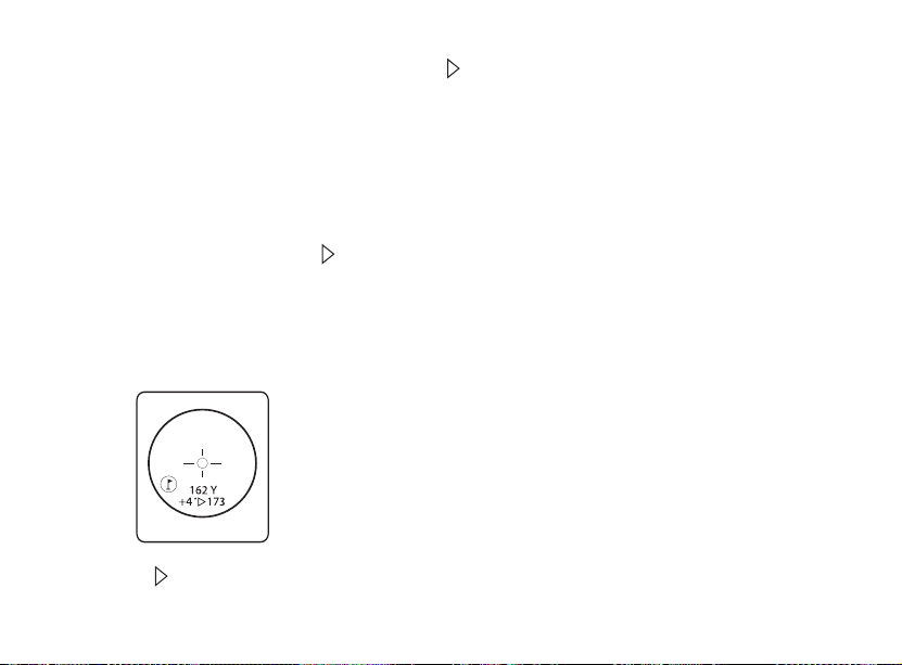
Once you have released the power button, a degree of angle and compensated range will be displayed beneath the
standard distance as seen below.
In this example, the true distance is 162 yards, slope is +4 degrees, and the compensated range is 173 yards. The “ ”
symbol means “Play-As”, so instead of playing as 162 yards, “play-as” 173 yards.
8
Page 11
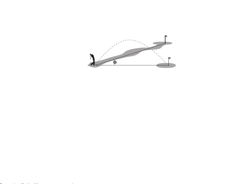
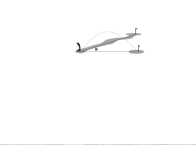
The Advantage of Slope+/-™
162 YA RDS
162 YARDS
X
4°
The distance to flag A in the drawing below is 162 yards. It is also 162 yards to flag B although it is on a slope.
However, if you were to play this hole as 162 yards, the ball (X) would fall short of the hole/flag because you did not
take slope into account.
The Truth about Slopes
Trying to determine slope angle with the naked eye can be rather deceiving. Most are not well versed to accurately
determine slope angle. For example, most golf courses average slope is approximately 4 degrees. A large slope at a golf
course is generally no more than 8 degrees. Of course this can vary, and that is why this device will measure slope
from -20 to 20 degrees.
Some real world examples may help clarify. A moderate roof pitch is 6/12, which means that the roof rises six inches
for every 12 inch horizontal distance. That equates to 26.5 degrees. You can scramble up this pitch when hanging
Christmas lights, but climbing that slope for the distance of a good golf shot on a course would be exhausting. To
retrieve a 200 yards shot, you would climb 300 feet up!
Golf Example: Let’s say you are a strong golfer with a 300 yard shot. At a 20 degree slope the Pin would be 50 feet
above you. In other words, you be driving the ball to the top of a 5 story building!!!
NOTE: For your convenience, the Slope +/-™ Mode also contains the PinSeeker® Mode/feature. If at any time
you prefer not to use the Slope +/-™ Mode, simply press the MODE button to get to PinSeeker® or Standard with
Automatic SCAN Mode.
™
9
Page 12

Standard with Automatic SCAN: This setting allows most targets to be distanced up to 1600 yards. Used for
moderately reflective targets that are typical of most distancing situations. The minimum distance in the standard
mode is 5 yards. To use the Automatic SCAN feature, simply hold down on the POWER button for approximately
3 seconds and SCAN the rangefinder from object to object while leaving the POWER button depressed. Automatic
SCAN will allow the range and display to be continuously updated very rapidly as multiple objects are targeted.
OPTICAL DESIGN
Magnification and Coatings
The Pro
1600 features a powerful 7x magnification monocular for viewing your target. Optics are Fully Multi-
™
Coated allowing maximum light transmission for optimum brightness, superb resolution and contrast for a clear
vivid image even in low light conditions such as dusk or dawn. A liquid crystal display (LCD) is mounted within the
optical system and when activated, displays a reticle for targeting, yards / meters, and Mode indicators. Inherent in
the manufacturing process are small black spots that appear in the optical system. These are a natural characteristic of
the LCD and cannot be fully eliminated in the manufacturing process. They do not affect the distancing performance
of the unit.
RainGuard® HD
The outer surfaces of the objective and eyepiece lenses are RainGuard® HD coated. RainGuard® HD is Bushnell’s
permanent, patented, hydrophobic (water repellant) lens coating that prevents fogging by causing condensation from
rain, sleet, snow or even your own breath to bead up into much smaller droplets than on standard coatings. Smaller
uniform droplets scatter less light which results in a clearer, brighter view.
TRIPOD MOUNT
Molded into the bottom of our is a threaded tripod mount that will allow you to attach to the following Bushnell
Golf Accessories:
10
Page 13

Golf Cart Mount: Attaches the rangefinder to your golf cart for easy access. Quick release clamp attaches to golf cart
and can be easily removed afterwards.
Push/Pull Cart Monopod: Steady your hand with this telescoping monopod. Simply attach rangefinder to the
monopod and insert into cart umbrella holder.
SPECIFICATIONS:
Dimensions: Measuring 1.7 x 5.1 x 3.7 inches
Weight: 12 oz.
Ranging Accuracy: +/- 1 yard
Range: 5-1600 Yards / 5-1463 Meters
Magnification: 7x
Objective Diameter: 26 mm
Optical Coatings: Fully Multi-Coated
Display: LCD
Power Source: 9-volt alkaline battery (user supplied)
Field Of View: 340 ft. @ 1000 yards
Extra Long Eye Relief: 19mm
Exit Pupil: 3.7 mm
100% Water Proof Construction
RainGuard® HD Coating
Built-In Tripod Mount
Includes case and strap
Patent #’s: 6,445,444 | 5,612,779 | 6,057,910 | 6,226,077 | 6,542,302 | 7,239,377 (205106)
11
Page 14

CLEANING
Gently blow away any dust or debris on the lenses (or use a soft lens brush). To remove dirt or fingerprints, clean with a soft
cotton cloth, rubbing in a circular motion. Use of a coarse cloth or unnecessary rubbing may scratch the lens surface and
eventually cause permanent damage. For a more thorough cleaning, photographic lens tissue and photographic-type lens
cleaning fluid or isopropyl alcohol may be used. Always apply the fluid to the cleaning cloth – never directly on the lens.
TWO-YEAR LIMITED WARRANTY
Your Bushnell product is warranted to be free of defects in materials and workmanship for two years after the date of purchase. In the event of a defect under
this warranty, we will, at our option, repair or replace the product, provided that you return the product postage prepaid. This warranty does not cover
damages caused by misuse, improper handling, installation, or maintenance provided by someone other than a Bushnell Authorized Service Department.
Any return made under this warranty must be accompanied by the items listed below:
1) A check/money order in the amount of $10.00 to cover the cost of postage and handling
2) Name and address for product return
3) An explanation of the defect
4) Proof of Date Purchased
5)
Product should be well packed in a sturdy outside shipping carton, to prevent damage in transit, with return postage prepaid to the address listed below:
IN U.S.A. Send To: IN CANADA Send To:
Bushnell Outdoor Products Bushnell Outdoor Products
Attn.: Repairs Attn.: Repairs
8500 Marshall Drive 25A East Pearce Street, Unit 1
Lenexa, Kansas 66214 Richmond Hill, Ontario L4B 2M9
12
Page 15

For products purchased outside the United States or Canada please contact your local dealer for applicable warranty information. In Europe you may also
contact Bushnell at: Bushnell Outdoor Products Gmbh
European Service Centre
MORSESTRASSE 4
D- 50769 KÖLN
GERMANY
Tél: +49 (0) 221 709 939 3
Fax: +49 (0) 221 709 939 8
This warranty gives you specific legal rights.
You may have other rights which vary from country to country.
©2008 Bushnell Outdoor Products
TROUBLE SHOOTING TABLE
If unit does not turn on - LCD does not illuminate:
• Depresspowerbutton.
• Checkandifnecessary,replacebattery.
If unit does not respond to key presses, replace the battery with a good quality 9 volt alkaline battery.
If unit powers down (display goes blank when attempting to power the laser):
• The battery is either weak or low quality. Replace the battery with a good quality 9 volt alkaline battery.
Heavy Duty alkaline batteries are NOT recommended.
If target range cannot be obtained:
• MakesureLCDisilluminated.
• Makesurethatthepowerbuttonisbeingdepressed.
• Makesurethatnothing,suchasyourhandornger,isblockingtheobjectivelenses(lensesclosesttothetarget)
that emit and receive the laser pulses.
• Makesureunitisheldsteadywhiledepressingpowerbutton.
13
Page 16

NOTE: The last range reading does not need to be cleared before ranging another target. Simply aim at the new target
using the LCD’s reticle, depress the power button and hold until new range reading is displayed.
Specifications, instructions, and the operation of these products are subject to change without notice.
FCC NOTE
This equipment has been tested and found to comply with the limits for a Class B digital device, pursuant to Part
15 of the FCC Rules. These limits are designed to provide reasonable protection against harmful interference in a
residential installation. This equipment generates, uses and can radiate radio frequency energy and, if not installed
and used in accordance with the instructions, may cause harmful interference to radio communications. However,
there is no guarantee that interference will not occur in a particular installation. If this equipment does cause harmful
interference to radio or television reception, which can be determined by turning the equipment off and on, the user
is encouraged to try to correct the interference by one or more of the following measures:
• Reorient or relocate the receiving antenna.
• Increase the separation between the equipment and receiver.
• Connect the equipment into an outlet on a circuit different from that to which the receiver is connected.
• Consult the dealer or an experienced radio/TV technician for help.
Shielded interface cable must be used with the equipment in order to comply with the limits for a digital
device pursuant to Subpart B of Part 15 of FCC Rules.
Specifications and designs are subject to change without any notice or obligation on the part of the manufacturer.
14
Page 17

Model: 205105/205106
Lit. #: 98-1342/12-08
FRANÇAIS
Page 18

Félicitations pour l’achat de votre Télémètre Laser Bushnell® Pro™ 1600 , notre télémètre laser le plus performant
pour les golfeurs et utilisé par plus de golfeur que toute autre marque. Le modèle Pro™ 1600 est un instrument
optique à laser de précision, conçu pour fournir de nombreuses années de service agréable. Ce livret vous permettra
d’obtenir les performances optimales du télémètre à laser précis car il décrit ses caractéristiques, ses réglages et son
entretien. Il est recommandé de lire ces instructions avant d’utiliser le PINSEEKER®1500 afin d’en obtenir les
performances les meilleures et la plus longue durée de service possible.
À revêtement caoutchouté
Construction
100 % étanche à l’eau
Objectif et
émetteur laser
Lentille avec
revêtement
RainGuard
Récepteur laser
16
®
HD
Alimentation
Réglage
dioptrique +/-2
Oculaire rotatif
avec RainGuard
®
HD
Afficheur en objectif
Mode
Monture de trépied
Compartiment de pile
Page 19

INTRODUCTION
Le modèle Pro™ 1600 Bushnell® est un télémètre à laser de pointe, de haute qualité, utilisant une technologie
numérique pour effectuer des mesures de distances comprises entre 5 et 1463 mètres (5 et 1600 yards). Mesurant juste
4,3 x 12,9 x 9,3 cm, pesant à peine 340 g, le télémètre Pro™ 1600 permet une étonnante mesure des distances avec
une précision de +/- 1 m. Avec ses modes de ciblage Selective Targeting,™ il dispose d’une qualité optique admirable,
d’une construction 100 % étanche à l’eau et du revêtement RainGuard® HD Bushnell.
EN QUOI CONSISTE NOTRE TECHNOLOGIE NUMÉRIQUE
Le modèle Pro™ 1600 émet des pulsions d’énergie infrarouge invisibles et sans danger pour les yeux. Le microprocesseur
numérique et la puce ASIC (circuit intégré spécifique d’application) sophistiqués du modèle Pro™ 1600 produisent
chaque fois des relevés de distance instantanés et exacts. La technologie numérique sophistiquée permet de calculer
instantanément les distances en mesurant le temps mis par chaque pulsion pour aller du télémètre à la cible et en
revenir.
PRÉCISION DE L’ÉVALUATION DES DISTANCES
La précision de l’évaluation des distances par le Pro™ 1600 est de plus ou moins un mètre/yard, dans la plupart des
cas. La plage d’évaluation maximale de l’instrument dépend de la réflectivité de la cible. Pour la plupart des objets,
la distance maximale est de 914 mètres (1 000 yards), mais elle peut aller jusqu’à 1463 mètres (1600 yards) pour des
objets très réfléchissants. Remarque: Les distances maximales sont plus longues ou plus courtes selon les propriétés de
réflectivité des cibles et selon les conditions de l’environnement au moment des mesures.
La couleur, le fini de surface, la taille et la forme de la cible affectent sa réflectivité et la plage de mesure. Plus la
couleur est vive, plus la plage est longue. Par exemple, le rouge est très réfléchissant et permet des plages plus longues
que le noir qui est la couleur la moins réfléchissante. Un fini brillant permet une plage plus longue qu’un fini mat.
L’évaluation de la distance d’une cible de petite taille est plus difficile que celle d’une cible de grande taille. L’angle de
la cible a aussi un effet. La visée d’une cible à un angle de 90 degrés (lorsque la surface de la cible est perpendiculaire
au trajet des pulsions d’énergie émises) permet une bonne plage de mesure alors que la visée d’une cible à angle aigu
réduit cette plage. En outre, l’éclairage (quantité de lumière solaire par exemple) affecte également les capacités
17
Page 20
d’évaluation de l’instrument. Moins il y a de lumière (ciel couvert par exemple), plus la plage maximale s’allonge.
Inversement, par grand soleil, la plage maximale diminue.
POUR COMMENCER
MISE EN PLACE DE LA PILE
Tout d’abord faire glisser le couvercle vers l’extérieur. Le volet
peut maintenant s’ouvrir. Insérer une pile alcline de 9 volt dans
l’emplacement comme indiqué, ensuite fermer le couvercle
batterie et le faire glisser jusqu’à temps qu’il soit vérrouillé dans
sa position. Le compartiment à pile a été conçu pour contenir
la pile uniquement lorsqu’elle est placée dans une position
correcte. Toutefois, si vous ne pouvez pas fermer le couvercle
de la pile, vérifi ez que la pile n’a pas été placée de manière
incorrecte.
REMARQUE : Utilisez uniquement des piles alcalines de haute
qualité. N’utilisez pas de piles à usage intensif ni de piles au
lithium. Il est recommandé de remplacer la pile au moins une
fois tous les 12 mois.
Indicateur de pile faible: Si l’indicateur Y (yards) ou M
(mètres) clignote continuellement, cela indique que la charge
de la pile est bientôt insuffi sante et qu’il est temps de remplacer
la pile alcaline de 9 volts.
RÉGLAGE DE L’OCULAIRE
Pour être confortable et éliminer la lumière superfl ue, le modèle
Pro™ 1600 est doté d’un oculaire rotatif. Pour les utilisateurs
18
Page 21

qui ne portent pas de lunettes, tournez l’œilleton dans le sens inverse des aiguilles d’une montre tout en le tirant,
jusqu’à ce qu’il reste en position complètement relevée. Le Pro™ 1600 fournit un dégagement oculaire extra long. Si
vous portez des lunettes, vérifiez que l’œilleton est abaissé ; cette position permet à l’œil d’être plus proche de la lentille
pour voir ainsi la largeur de champ maximale. Pour abaisser l’œilleton à partir de sa position complètement relevée,
tournez-le dans le sens des aiguilles d’une montre tout en poussant légèrement vers le bas. Il est également possible de
le placer en position intermédiaire, entre la position de relevage maximal et celle d’abaissement maximal, ce qui peut
mieux convenir à certaines personnes.
Le modèle Pro™ 1600 est aussi équipé d’un oculaire réglable (réglage dioptrique +/- 2) qui permet d’effectuer la mise
au point de l’afficheur LCD par rapport à l’image. Il suffit de tourner la bague de réglage dioptrique jusqu’à ce que
l’afficheur LCD soit au point.
MODE D’EMPLOI EN BREF
Tout en regardant dans l’oculaire à grossissement de 7 x, appuyez une fois sur le bouton de marche pour activer
l’afficheur à cristaux liquides (LCD) intégré. Placez le cercle de visée (situé au centre du champ de vision) sur une cible
se trouvant à au moins 5 mètres (5 yards); maintenez le bouton de marche enfoncé jusqu’à ce que la mesure de distance
soit affichée près du bas de l’afficheur intégré. La croisée de fils entourant le cercle de visée indique que le rayonnement
laser est en cours de transmission. Une fois la mesure de distance acquise, vous pouvez relâcher le bouton de marche.
La croisée de fils entourant le cercle de visée disparaît une fois que le bouton de marche a été relâché (c’est-à-dire que
le rayonnement laser n’est plus en cours de transmission). Remarque: Une fois activé, l’afficheur LCD du Pro™ 1600
reste actif et indique le dernier relevé de distance pendant 30 secondes. Vous pouvez appuyer de nouveau sur le bouton
de marche à tout moment pour viser une autre cible. Comme avec tout dispositif à laser, il est déconseillé d’observer
directement les émissions avec des lentilles grossissantes, pendant une période prolongée. La durée maximale pendant
laquelle le rayonnement laser est transmis est de 10 secondes. Pour viser à nouveau, rappuyez sur le bouton.
INDICATEURS DE L’AFFICHEUR À CRISTAUX LIQUIDES (LCD)
L’afficheur LCD du Pro™ 1600 comporte des indicateurs lumineux qui avertissent l’utilisateur: unité de mesure
choisie, moment où le rayonnement laser est émis, moment où la distance à la cible est acquise et modes de ciblage.
Consultez ci-dessous le résumé de ces caractéristiques :
19
Page 22

CHOIX D’UNITÉS DE MESURE
Le modèle Pro™ 1600 peut mesurer les distances en mètres ou en yards. Les indicateurs d’unités de mesure se trouvent
à la partie inférieure droite de l’afficheur. Pour choisir entre les yards et les mètres, appuyez brièvement sur le bouton
de MARCHE (sur le haut de l’instrument) pour l’activer ; regardez à travers l’oculaire et maintenez le bouton MODE
(côté gauche de l’oculaire) enfoncé pendant environ 5 secondes. Lors du passage des yards aux mètres, un changement
d’unité de mesure est indiqué par l’allumage de la lettre M pour MÈTRE alors que l’indicateur Y pour YARD s’éteint.
Lors du passage des mètres aux yards, c’est l’inverse qui se produit. Le Pro™ 1600 revient au dernier réglage utilisé
chaque fois qu’il est remis en marche.
LASER ACTIF
La croisée de fils entourant le cercle de visée indique que le rayonnement laser est en cours de transmission. Une fois
la mesure de distance acquise, vous pouvez relâcher le bouton de marche. La croisée de fils entourant le cercle de
visée disparaît une fois que le bouton de marche a été relâché (c’est-à-dire que le rayonnement laser n’est plus en cours
de transmission).
MODES DE CIBLAGE SÉLECTIF (SELECTIVE TARGETING™)
Le modèle Pro™ 1600 a été spécialement conçu pour les golfeurs. Les modes de ciblage sélectif permettent d’ajuster
les paramètres de fonctionnement de l’instrument à la situation et à l’environnement présents. Pour passer d’un mode
à un autre, appuyez une fois sur le bouton de MARCHE pour activer l’instrument. Tout en regardant dans l’oculaire,
appuyez brièvement sur le bouton MODE. Les différents modes de ciblage disponibles et indicateurs de modes sont
décrits ci-dessous :
PinSeeker (indicateur d’affichage – ) Est-il difficile de connaître la distance jusqu’au drapeau? Ce mode perfectionné
permet une acquisition facile de la distance jusqu’au drapeau sans obtenir par erreur la distance d’autres cibles d’arrièreplan (arbres, par ex.) qui ont un signal plus fort.
20
Page 23
Une fois dans ce mode, appuyez sur le bouton de MARCHE pour activer l’instrument. Puis alignez le réticule
du cercle de visée sur le drapeau dont vous voulez connaître la distance. Ensuite, maintenez enfoncé le bouton
de MARCHE et déplacez lentement le télémètre sur le drapeau ou l’objet en question jusqu’à ce qu’un cercle
entoure l’indicateur du drapeau. Si le rayonnement laser reconnaît plusieurs objets (par ex. un drapeau et des arbres
à l’arrière-plan), la distance au drapeau est affichée et un cercle entoure l’indicateur PinSeeker, informant l’utilisateur
que la distance au drapeau (par ex. l’objet le plus proche) apparaît à l’afficheur LCD (comme indiqué ci-dessous).
Il peut y avoir des cas où le rayonnement laser ne voit qu’un seul objet sur sa trajectoire. La distance est alors affichée
mais comme plusieurs objets n’ont pas été détectés, l’indicateur du drapeau n’est pas entouré d’un cercle.
CONSEIL: Tout en appuyant sur le bouton de MARCHE, vous pouvez déplacer lentement l’instrument d’un objet
à un autre et forcer ainsi le rayonnement laser à toucher plusieurs objets, pour vérifier que seule la distance des objets
les plus proches reconnus par le rayonnement laser est affichée.
Une fois que le dispositif s’est éteint, l’appareil revient toujours par défaut au dernier mode utilisé.
21
Page 24
PinSeeker with Slope +/-™ (Indicateur d’affichage - ° ) Ce mode perfectionné ne se trouve que sur le modèle 20-
5106 (Pro™ 1600 with Slope +/-™). Le modèle 20-5106 est doté d’un inclinomètre à base d’accéléromètre intégré
qui permet l’affichage numérique de l’angle de pente exact, de -20 à +20 degrés d’élévation, avec une précision de +/1,0 degré. Le mode Slope +/-™ calcule automatiquement la distance compensée par l’angle en fonction des mesures
de distance et d’angle de pente déterminées par le télémètre à laser et l’inclinomètre intégré. Ces données sont alors
combinées avec des formules algorithmiques internes concernant l’utilisation moyenne des clubs et les trajectoires
des balles. La mesure de distance compensée par l’angle renseigne sur la manière de jouer (c’est-à-dire ajouter de la
distance s’il s’agit d’une montée, soustraire de la distance s’il s’agit d’une descente).
Comment utiliser Slope +/-™
Une fois dans ce mode, vous voyez “ ° ” dans le champ de vision, ce qui indique que vous êtes au mode Slope +/(pente). Appuyez sur le bouton de MARCHE pour obtenir la distance jusqu’au drapeau ou jusqu’à d’autres objets.
Une fois la distance affichée, continuez à appuyer sur le bouton de MARCHE pendant environ 2 secondes, tout en
maintenant le cercle de visée sur le drapeau et l’instrument aussi immobile que possible, pour donner à l’inclinomètre
le temps nécessaire à la mesure de la pente. Relâchez alors le bouton de MARCHE. Une fois que vous avez relâché le
bouton de marche, une mesure d’angle en degrés et une distance compensée sont affichées sous la distance standard,
comme représenté ci-dessous.
Dans cet exemple, la distance réelle est de 162 yards, la pente de +4 degrés et la distance compensée de 173 yards.
Le symbole “ ” signifie « jouer comme » ; par conséquent, au lieu de jouer comme 162 yards, « jouer comme »
173 yards.
22
Page 25
162 YA RDS
162 YARDS
X
4°
L’avantage de Slope+/-™
Dans le schéma ci-dessous, la distance jusqu’au drapeau A est de 162 yards. Elle est aussi de 162 yards jusqu’au
drapeau B mais elle est sur une pente. Si vous deviez jouer ce coup comme 162 yards, la balle (X) ne parviendrait pas
au trou/drapeau parce que la pente n’a pas été prise en compte.
La vérité sur les pentes
La vision de l’angle de pente à l’œil nu est souvent trompeuse. La plupart d’entre nous ne sommes pas entraînés à
déterminer avec précision l’angle d’une pente. Par exemple, sur la plupart des terrains de golf, la pente moyenne est
d’environ 4 degrés. Une grande pente d’un terrain de golf n’est généralement pas de plus de 8 degrés. Bien sûr, les
terrains varient et c’est pourquoi cet instrument peut mesurer les pentes allant de -20 à +20 degrés.
Voici pour clarifier quelques exemples simples : L’inclinaison modérée d’un toit est de 6/12, ce qui signifie que le toit
s’élève de six pouces (15 cm) pour 12 pouces (30 cm) de distance horizontale. Ceci correspond à 26,5 degrés. Vous
pouvez escalader cette inclinaison pour suspendre des éclairages de Noël, mais la montée de cette pente sur la distance
d’un bon coup, sur un terrain de golf, serait épuisante. Pour récupérer un coup de 182 m (200 yards), il vous faudrait
monter de 91 m (300 pieds) !
Exemple de golf : Supposons que vous êtes bon golfeur avec un coup de 274 m (300 yards). Avec une pente de
20 degrés, le drapeau de trou serait 15 m (50 pieds) au-dessus de vous. Autrement dit, vous devriez envoyer la balle
en haut d’un bâtiment de 5 étages !
REMARQUE : Pour votre commodité, le mode Slope +/-™ contient aussi le mode/la fonction PinSeeker.® Si, à un
moment quel qu’il soit, vous préférez ne pas utiliser le mode Slope +/-™, appuyez simplement sur le bouton MODE
pour passer à PinSeeker® ou Standard with Automatic SCAN Mode.™
23
Page 26

Standard avec exploration automatique (SCAN) — Ce réglage permet la mesure de distances de cibles jusqu’à
1463 m (1600 yd). Utilisé pour des cibles modérément réfléchissantes, typiques de la plupart des situations. La
distance minimum au mode standard est de5 mètres (5 yards). Pour utiliser la fonction d’exploration automatique
SCAN, maintenez simplement le bouton de MARCHE enfoncé pendant environ 3 secondes et déplacez le télémètre
d’un objet à un autre tout en continuant à appuyer sur le bouton de MARCHE. Cette fonction permet l’évaluation et
l’affichage mis à jour très rapidement des distances de cibles en continu, à mesure que de multiples objets sont visés.
CONCEPTION OPTIQUE
Grossissement et traitements
Le modèle Pro™ 1600 dispose d’un puissant monoculaire à grossissement de 7 x pour la visée des cibles. Les
éléments optiques sont traités multicouches toutes surfaces, procurant une transmission maximale de la lumière,
pour une luminosité optimale, une résolution et un contraste remarquables, offrant des images claires même en
situations de faible luminosité, comme au crépuscule ou à l’aube. Un afficheur à cristaux liquides (LCD) est monté
à l’intérieur du système optique ; une fois activé, il présente un réticule pour la visée, des indicateurs d’unités de
mesure (mètres ou yards) et des indicateurs de mode. De petits points noirs, inhérents au procédé de fabrication,
sont visibles dans le système optique. Ils constituent une caractéristique naturelle de l’afficheur à cristaux liquides et
ne peuvent être totalement éliminés lors de la fabrication. Ils n’affectent d’aucune manière l’évaluation des distances
par l’instrument.
RainGuard
Les surfaces extérieures des lentilles de l’objectif et de l’oculaire sont enduites de RainGuard® HD. RainGuard® HD
est le revêtement de lentille permanent, hydrofuge (qui repousse l’eau), breveté de Bushnell qui empêche la formation
de buée en transformant la condensation due à la pluie, au grésil, à la neige ou même au souffle de l’utilisateur en
gouttelettes bien plus petites que sur des revêtements standards. Les gouttelettes uniformes, plus fines diffusent moins
de lumière et l’on obtient ainsi une image plus claire et plus lumineuse.
ADAPTATEUR TRÉPIED
Un support de trépied fileté est moulé au bas de votre Pro 1600 et vous permettra d’attacher les Acccessoires de Golf
Bushnell suivant:
24
Page 27

Support de la Voiturette de Golf: Fixer le télémètre à votre voiturette de golf pour un accès facile. Une pince à
dégraphage rapide s’attache à la voiturette de golf et peut être facilement enlevée après coup.
Pied de voiturette Push/Pull: S’assurer que votre main ne tremble pas avec le pied télécopique. Fixer simplement le
télémètre sur le pied et insérer le dans le porte parapluie de la voiturette.
SPÉCIFICATIONS :
Dimensions: mesure 4,3 x 12,9 x 9,3 cm
Poids: 340 g
Précision de l’évaluation des distances: +/- 1 m (1 yard)
Portée: 5 à 1463 mètres (5 à 1600 yards)
Grossissement: 7 x
Diamètre de l’objectif 26 mm
Traitement optique: multicouches, toutes surfaces
Afficheur: à cristaux liquides
Source d’alimentation: pile alcaline de 9 volts (fournie par l’utilisateur)
Largeur de champ: 103 m (340 pi) à 914 m (1 000 yards)
Dégagement oculaire extra long: 19 mm
Pupille de sortie: 3,7 mm
Construction 100 % étanche à l’eau
Revêtement HD RainGuard
®
Monture de trépied intégrée
Étui et sangle inclus
Brevet#’s: 6,445,444 | 5,612,779 | 6,057,910 | 6,226,077 | 6,542,302 | 7,239,377 (205106)
NETTOYAGE
Soufflez délicatement pour éliminer poussière ou débris des lentilles (ou utilisez une brosse à poils doux pour lentilles).
25
Page 28

Pour retirer la saleté ou les traces de doigts, nettoyez avec un tissu en coton doux, en frottant d’un mouvement
circulaire. L’utilisation d’un tissu grossier ou un frottement inutile risque de rayer la surface de la lentille et de la
détériorer de façon définitive. Pour un nettoyage plus profond, vous pouvez utiliser des tissus spéciaux pour appareils
photo, des liquides de nettoyage pour lentilles photographiques ou de l’alcool isopropylique. Appliquez toujours le
liquide sur un chiffon, jamais directement sur la lentille.
GARANTIE LIMITÉE DE DEUX ANS
Votre produit Bushnell est garanti exempt de défauts de matériaux et de fabrication pendant deux ans après la date d’achat. Au cas où un défaut apparaîtrait
sous cette garantie, nous nous réservons l’option de réparer ou de remplacer le produit, à condition de nous le renvoyer en port payé. La présente garantie ne
couvre pas les dommages causés par une utilisation, une manipulation, une installation incorrectes ou un entretien incorrect ou fourni par quelqu’un d’autre
qu’un centre de réparation agréé par Bushnell.
Tout retour effectué dans le cadre de la présente garantie doit être accompagné des articles indiqués ci-dessous :
1) un chèque ou mandat d’une somme de 10,00 $ US pour couvrir les frais d’envoi et de manutention
2) le nom et l’adresse pour le retour du produit
3) une description du défaut constaté
4) la preuve de la date d’achat
5) Le produit doit être emballé soigneusement, dans un carton d’expédition solide, pour éviter qu’il ne soit endommagé durant le transport ; envoyez-le
en port payé, à l’adresse indiquée ci-dessous :
Aux États-Unis, envoyez à : Au CANADA, envoyez à :
Bushnell Outdoor Products Bushnell Outdoor Products
Attn.: Repairs Attn.: Repairs
8500 Marshall Drive 25A East Pearce Street, Unit 1
Lenexa, Kansas 66214 Richmond Hill, Ontario L4B 2M9
Pour les produits achetés en dehors des États-Unis et du Canada, veuillez contacter votre distributeur local pour tous renseignements concernant la garantie.
En Europe, vous pouvez aussi contacter Bushnell au : Bushnell Outdoor Products Gmbh
European Service Centre
26
MORSESTRASSE 4
D- 50769 KÖLN
ALLEMAGNE
Page 29

Tél. : +49 (0) 221 709 939 3
Fax : +49 (0) 221 709 939 8
La présente garantie vous donne des droits légaux spécifiques.
Vous pouvez avoir d’autres droits qui varient selon les pays.
©2008 Bushnell Outdoor Products
TABLEAU DES PROBLÈMES RENCONTRÉS
Si l’instrument ne se met pas en marche - l’afficheur ne s’allume pas :
• Appuyezsurleboutondemarche.
• Vériezlapileetremplacez-lasinécessaire.
Si l’ instrument ne réagit pas aux pressions sur les boutons, remplacez la pile par une pile alcaline de 9 volts, de
bonne qualité.
Si l’instrument s’éteint (l’afficheur se vide quand on essaie d’activer le laser) :
• Chargedelapileinsufsanteoupiledemauvaisequalité.Remplacezlapileparunepilealcalinede9volts,de
bonne qualité. Il est DÉCONSEILLÉ d’utiliser des piles alcalines pour usage intensif.
S’il est impossible d’obtenir la distance
• Vériezquel’afcheurestallumé.
• Vériezqueleboutondemarcheestenfoncé.
• Vériezquerien(mainoudoigt)nebloquel’objectif(lentillelaplusprochedelacible)etn’entravel’émissionet
la réception des pulsions d’énergie laser.
• Vériezquel’instrumentresteimmobilependantquevousappuyezsurleboutondemarche.
REMARQUE: Il n’est pas nécessaire d’effacer le dernier relevé avant de viser une autre cible. Il suffit de viser une
nouvelle cible à l’aide du réticule de l’afficheur, d’appuyer sur le bouton de marche et de le maintenir enfoncé jusqu’à
ce que la nouvelle distance apparaisse.
27
Page 30

Les spécifications, les instructions et l’utilisation de ces produits sont susceptibles de modification sans préavis.
Remarque relative à la FCC (Commission fédérale des télécommunications)
Ce matériel a été testé et s’est révélé être conforme aux limites d’un dispositif numérique de classe B, conformément
à la section 15 de la réglementation FCC. Ces limites ont été établies pour assurer une protection raisonnable
contre les parasites nuisibles dans les immeubles résidentiels. Ce matériel produit, utilise et peut émettre de l’énergie
radiofréquence; en conséquence, s’il n’est pas installé et utilisé en conformité avec les instructions, il risque de
provoquer des parasites nuisibles aux communications radio. Toutefois, il n’est pas garanti que des parasites ne se
produiront pas dans une installation particulière. Si ce matériel causait des parasites nuisibles à la réception radio ou
télévision, qui peuvent être déterminés en mettant le matériel hors tension puis sous tension, l’utilisateur peut essayer
de remédier au problème en appliquant l’une ou plusieurs des mesures suivantes :
•Réorienteroudéplacerl’antennederéception.
•Augmenterladistanceséparantlematérieldurécepteur.
•Connecter lematérielà une prisedecourant ou àuncircuit différent(e) decelui (celle) auquel(àlaquelle) le
récepteur est relié.
•Consulterleconcessionnaireouuntechnicienradio/TVexpérimenté.
Le câble d’interface blindé doit être utilisé avec le matériel afin d’être conforme aux limites d’un dispositif numérique,
conformément à la sous-section B de la section 15 de la réglementation FCC.
28
Page 31

Model: 205105/205106
Lit. #: 98-1342/12-08
ESPAÑOL
Page 32

Lo felicitamos por su compra del telémetro de rayos laser Bushnell® Pro™ 1600, nuestro principal telémetro de rayos
laser para golfistas y utilizado por más jugadores profesionales de golf que cualquier otra marca. El Pro™ 1600es un
instrumento óptico de telemetría láser de precisión diseñado para que disfrute su utilización por muchos años. Este
folleto le ayudará a lograr un rendimiento óptimo explicando sus ajustes y características así como la forma de cuidar
de este instrumento óptico de telemetría láser de precisión. Para asegurar su rendimiento óptico y mayor duración, lea
estas instrucciones antes de usar su Pro™ 1600.
Armadura de caucho &
Construcción
impermeable al 100%
Transmit Objetivo y
transmisión de láser
Lentes con
revestimiento
Rainguard® HD
30
Encendido
Ajuste dióptrico
de +/-2
Ocular desplegable
con RainGuard
®
Visualización en pantalla
Modalidad
Montura para trípode
Compartimiento de la pilaReceptor láser
Page 33

INTRODUCCIÓN
Su Pro™ 1600 de Bushnell® es un telémetro de rayos láser avanzado que utiliza Tecnología Digital y permite lecturas
de distancia comprendidas entre 5 y 1600 yardas / 5 a 1463 metros. El Pro™ 1600 mide solamente 1,7 x 5,1 x 3,7
pulgadas y pesa 12 onzas, pero ofrece un rendimiento de medición de distancias preciso y sorprendente hasta +/una yarda/metro. El Pro™ 1600 presenta modalidades de Selective Targeting™, una calidad óptica extraordinaria,
construcción 100% impermeable y el revestimiento RainGuard® HD de Bushnell.
CÓMO FUNCIONA NUESTRA TECNOLOGÍA DIGITAL
El Pro™ 1600 emite impulsos de energía infrarroja que son invisibles y seguros para la vista. El microprocesador
digital avanzado y el chip ASIC (circuito integrado específico para una aplicación) del Pro™ 1600, ofrecen lecturas
instantáneas y precisas en todo momento. Con una tecnología digital sofisticada, calcula instantáneamente las
distancias midiendo el tiempo que tarda cada impulso en desplazarse desde el telémetro hasta el blanco y el regreso.
PRECISIÓN PARA MEDIR DISTANCIAS
La precisión para medir las distancias del Pro™ 1600 es de más o menos una yarda o metro en la mayoría de los casos.
El alcance máximo del instrumento dependerá de la reflectividad del blanco. La distancia máxima para la mayor parte
de los objetos es de 1000 yardas / 914 metros, mientras que en el caso de los objetos altamente reflectantes es de 1600
yardas / 1463 metros. Nota: Podrá obtener distancias máximas más largas o cortas dependiendo de las propiedades
reflectantes de un blanco concreto y de las condiciones medioambientales del momento en que se mide la distancia
hasta un objeto.
El color, acabado de la superficie, tamaño y forma del blanco afectarán la reflectividad y el alcance. Cuanto más
brillante es el color, mayor será el alcance de la medición. Por ejemplo, el rojo es altamente reflectante y permite hacer
mediciones a más distancia que el color negro, que es el color menos reflectante. Un acabado brillante proporciona una
distancia de medición mayor que uno mate. Un blanco pequeño es más difícil de medir que un blanco más grande. El
ángulo hasta el blanco afecta también la medición. Disparar a un blanco, a un ángulo de 90 grados (donde la superficie
del blanco es perpendicular a la trayectoria de vuelo de los impulsos de energía emitidos) proporciona una buena
medición de la distancia, mientras que un ángulo agudo, por otra parte, ofrece unas posibilidades limitadas. Además,
las condiciones de luz (por ejemplo, la cantidad de luz solar) afectarán la capacidad de medir distancias de la
31
Page 34

unidad. A menos luz (tal como un día nublado) mayor será el alcance máximo de la unidad. De igual forma, los días
muy soleados disminuirán el alcance máximo de la unidad.
PARA EMPEZAR
INSERTAR LA PILA
Primero deslice la puerta hacia afuera. Ahora se puede abrir
la puerta de bisagras. Introduzca una batería alcalina de 9
voltios en la ranura como se muestra, y cierre la puerta del
compartimento de la batería deslizándola hasta que bloquee en
su lugar. La ranura para la pila fue diseñada para alojar la pila
en la posición correcta. Por lo tanto, si usted no puede cerrar la
puerta del compartimento de pilas, verifi que que la pila haya
sido instalada correctamente.
NOTA: Use solamente pilas alcalinas de buena calidad. No
utilice pilas para usos industriales o de litio. Se recomienda que
la pila se sustituya una vez cada 12 meses.
Indicador de Pila Baja: Si el indicador Y (yardas) o M (metros)
parpadea continuamente o “IoB” se muestra en la pantalla del
visor, la batería se está bajando y la batería alcalina de 9 voltios
se debe cambiar.
AJUSTE DEL OCULAR
Su Pro™ 1600 dispone de un ocular desplegable diseñado
para ofrecer un mayor confort y eliminar la luz superfl ua. Para
los usuarios que no usen anteojos, girar la ocular a izquierdas
mientras tira del mismo hasta que quede fi jo en la posición
32
Page 35

completamente “arriba”. El Pro™ 1600 ofrece una distancia extra de la pupila. Si usa anteojos, asegúrese de que
la ojera esté en la posición bajada, de esta forma su ojo estará más cerca de la lente del ocular y podrá ver todo el
campo de visión. Para bajar la ojera desde la posición completamente “arriba”, gírela a derechas mientras la empuja
ligeramente hacia abajo. También es posible poner la ojera en posiciones “intermedias”, entre completamente arriba y
completamente abajo, que podría ser mejor para algunas personas.
El Pro™ 1600 está equipado también con un ocular ajustable (ajuste dióptrico de +/- 2) que permite enfocar la imagen
y la pantalla LCD. Sólo hay que girar el ajuste dióptrico hasta que la pantalla LCD esté enfocada.
RESUMEN DE FUNCIONAMIENTO
Mientras mira por el ocular de 7x, pulse el botón de encendido una vez para activar la pantalla de cristal líquido
incorporada (LCD). Apunte el círculo de puntería (ubicado en el centro del campo de visión) a un blanco que esté
a 5 yardas por lo menos, pulse y mantenga pulsado el botón de encendido hasta que se visualice la lectura de la
distancia cerca de la parte inferior de la pantalla. La cruz reticular que rodea el círculo de puntería indica que se está
transmitiendo el rayo láser. Una vez adquirida la distancia, suelte el botón de encendido. Una vez que se suelta el
botón de encendido, la cruz reticular alrededor del círculo de puntería desaparece (es decir, la transmisión de rayo láser
cesa). Nota: Una vez activada, la pantalla LCD del Pro™ 1600 permanecerá activa y mostrará la medición de la última
distancia durante 30 segundos. Puede pulsar otra vez el botón de encendido en cualquier momento para determinar la
distancia hasta un nuevo blanco. Como ocurre con cualquier dispositivo láser, no se recomienda mirar directamente
a las emisiones durante mucho tiempo con lentes de aumento. El tiempo máximo de transmisión (disparo) del rayo
láser es de 10 segundos. Para repetir el disparo, pulse el botón otra vez.
INDICADORES DE LA PANTALLA DE CRISTAL LÍQUIDO (LCD)
La pantalla LCD del Pro™ 1600 incorpora indicadores iluminados que le indican la unidad de medida, cuando el
rayo láser está activamente disparando, cuando se ha adquirido el blanco y la modalidades de determinación del
blanco. A continuación se ofrece un resumen de estas características:
33
Page 36

OPCIONES DE LA UNIDAD DE MEDIDA
El Pro™ 1600 puede usarse para medir distancias en yardas o metros. Los indicadores de la unidad de medida
están situados en la parte inferior derecha de la pantalla LCD. Para seleccionar entre yardas y metros, pulse y suelte
rápidamente el botón de encendido (POWER) para encender la unidad (situado en la parte superior de la unidad),
mire por el ocular, oprima el botón “MODE” (lado izquierdo del ocular) y manténgalo oprimido durante 5 segundos
aproximadamente. Si va a cambiar de yardas a metros, se indicará un cambio de la unidad de medida mediante la
iluminación de la M del indicador, mientras que el indicador Y de yardas permanece apagado. Si va a cambiar de
metros a yardas, ocurrirá el caso contrario. Cada vez que se encienda la unidad, el Pro™ 1600 regresará a la posición
de la última unidad de medida que se usó.
LÁSER ACTIVO
La cruz reticular que rodea el círculo de puntería indica que se está transmitiendo el rayo láser. Una vez adquirida la
distancia, suelte el botón de encendido. Una vez que se suelta el botón de encendido, la cruz reticular alrededor del
círculo desaparece (es decir, la transmisión de rayo láser cesa).
MODALIDADES DE SELECTIVE TARGETING™ (DETERMINACIÓN SELECTIVA DEL BLANCO)
El Pro™ 1600 se ha diseñado especialmente pensando en los golfistas. Las modalidades de selección selectiva del blanco
permiten ajustar los parámetros de rendimiento de la unidad para adecuarlos a su situación y entorno específicos. Para
pasar de una modalidad a otra, pulse el botón de encendido (POWER) una vez para encender la unidad. Mientras
mira por el ocular, pulse el botón MODE y suéltelo rápidamente. Las diferentes modalidades de determinación del
blanco que hay disponibles, y los indicadores de modalidad son los siguientes:
PinSeeker (Indicador LCD – ) ¿Ha tenido alguna vez dificultad en obtener la distancia hasta la bandera? Esta
modalidad avanzada facilita la adquisición de la bandera sin obtener por descuido las distancias hasta los blancos del
fondo (por ej., árboles) que tiene una señal más fuerte.
34
Page 37

Una vez que esté en esta modalidad, pulse el botón de encendido (POWER) para encender la unidad. En seguida
apunte la retícula circular a la bandera hasta la que desea medir la distancia. Después, pulse y mantenga oprimido
el botón de encendido (POWER) y desplace lentamente el rayo láser sobre la bandera o el objeto deseado hasta que
un círculo rodee al indicador de bandera. Si el rayo láser reconoce más de un objeto (por ej., la bandera y árboles de
fondo), se visualizará la distancia hasta la bandera y un círculo rodeará el indicador PinSeeker, informando al usuario
de que se está visualizando en la pantalla LCD la distancia hasta la bandera (es decir, el objeto más cercano). Es posible
que algunas veces el rayo láser vea solamente un objeto en su trayectoria. En ese caso, se visualizará la distancia, pero
debido a que no se adquirió más de un objeto, no aparecerá un círculo rodeando el indicador de bandera.
CONSEJO: Mientras pulsa el botón de encendido (POWER), puede desplazar lentamente el dispositivo de un objeto
a otro y forzar intencionalmente al rayo láser a hacer blanco en varios objetos para asegurarse de que solamente está
visualizando el objeto más cercano reconocido por el láser.
Una vez que se apague el dispositivo, la unidad volverá siempre a la última modalidad usada.
35
Page 38

PinSeeker con Slope +/-™ (Indicador LCD - ° ) Esta modalidad avanzada se encuentra solamente en el modelo
20-5106 (Pro™ 1600 with Slope +/-™). El modelo 20-5106 está provisto de un inclinómetro basado en acelerómetro
que muestra digitalmente el ángulo de inclinación entre -20 y +20 grados de elevación con una precisión de +/- 1,0
grado. La modalidad Slope +/-™ calculará automáticamente un alcance con compensación de inclinación basado en
la distancia y el ángulo de inclinación determinados por el telémetro de rayos láser y el inclinómetro incorporado.
Después, estos datos se combinan con fórmulas algorítmicas internas relacionadas con el uso promedio del club y las
trayectorias de las pelotas. La medición del alcance con compensación de inclinación proporciona la dirección en que
debe hacerse el tiro (es decir, añadir distancia si es una subida y restar si es una bajada).
Cómo usar el Slope +/-™
Una vez que esté en esta modalidad, verá una indicación “ ° ” en el campo de visión informándole que se encuentra
en la modalidad de Slope +/-. Pulse el botón de encendido (POWER) para obtener la distancia hasta la bandera u otros
objetos. Una vez que se visualice el blanco, continúe oprimiendo el botón de encendido durante aproximadamente
2 segundos mientras apunta el círculo de puntería a la bandera y mantiene la unidad lo más estable posible, para que el
inclinómetro tenga tiempo suficiente para medir la inclinación. Suelte el botón de encendido (POWER). Después de
soltar el botón de encendido, debajo de la distancia normal se visualizará un grado de ángulo y el alcance compensado,
como se muestra abajo.
En este ejemplo, la distancia verdadera es 162 yardas, la inclinación es +4 grados y el alcance compensado es
173 yardas. El símbolo “ ” significa “Jugar como”, por lo tanto, en vez de jugar como 162 yardas, debe “jugar como”
173 yardas.
36
Page 39

La ventaja del Slope +/-™
162 YA RDS
162 YARDS
X
4°
La distancia hasta la bandera A en el dibujo siguiente es de 162 yardas. También son 162 yardas hasta la bandera B
aunque esta se encuentra en una pendiente. Sin embargo, si jugara este hoyo como uno de 162 yardas, la pelota (X)
caería lejos del hoyo/bandera porque no tomó en cuenta la pendiente.
La verdad acerca de las pendientes
Tratar de determinar el ángulo de inclinación a simple vista puede inducir a error. La mayoría no tiene la experiencia
para determinar exactamente el ángulo de pendiente. Por ejemplo, la pendiente media en la mayoría de los campos
de golf es de aproximadamente 4 grados. Por lo general, en un campo de golf la pendiente más grande no tiene
más de 8 grados. Por supuesto que esto puede variar, y es por eso que este dispositivo medirá las pendientes entre
-20 y 20 grados.
Algunos ejemplos reales pueden ayudar a clarificar esto. Una inclinación moderada de techo es 6/12, lo que significa
que el techo se eleva seis pulgadas por cada distancia horizontal de 12 pulgadas. Eso equivale a 26,5 grados. Puede
subir gateando esta inclinación para colgar las luces de Navidad, pero subir esta pendiente cubriendo la distancia de un
buen tiro de golf en una cancha sería agotador. ¡Para recuperar un tiro de 200 yardas, tendría que subir 300 pies!
Ejemplo de golf: Digamos que usted es un golfista fornido con un tiro de 300 yardas. A una pendiente de 20 grados
el banderín de hoyo estaría 50 pies más arriba. ¡En otras palabras, al golpear la pelota la estaría lanzando a la parte
superior de un edificio de 5 pisos!
NOTA: Para su conveniencia, la modalidad Slope +/-™ contiene también la modalidad/función PinSeeker.® Si en
cualquier momento prefiere no utilizar la modalidad Slope +/-™, sólo tiene que pulsar el botón MODE para obtener
la modalidad PinSeeker® o Standard with Automatic SCAN Mode™ (Estándar con SCAN automático).
37
Page 40

Estándar con SCAN automático Esta configuración permite determinar la distancia hasta la mayor parte de los
blancos situados a una distancia de hasta unas 1600 yardas. Se usa para blancos moderadamente reflectivos que
son típicos en la mayoría de las situaciones de determinación de la distancia. La distancia mínima en la modalidad
estándar es de 5 yardas. Para usar el SCAN automático, sólo tiene que mantener pulsado el botón POWER durante
3 segundos aproximadamente y desplazar el telémetro de un objeto a otro mientras deja el botón POWER oprimido.
El SCAN automático permitirá actualizar continuamente el alcance y la visualización a medida que se determina la
distancia hasta múltiples objetos
DISEÑO ÓPTICO
Aumento y revestimientos
El Pro™ 1600 presenta un potente monocular con un aumento de 7x para visualizar el blanco. Dispone de una óptica
de múltiples capas que permite la máxima transmisión de luz para ofrecer un brillo óptimo, una resolución y contraste
magníficos para lograr una imagen viva y clara hasta en condiciones de luz baja como al anochecer y al amanecer. Una
pantalla de cristal líquido (LCD) se monta dentro del sistema óptico y, cuando se activa, muestra una retícula para
apuntar al blanco, designaciones en yardas/metros e indicadores de modalidad. Inherente en el proceso de fabricación,
pueden aparecer unos puntitos negros en el sistema óptico. Se trata de una característica natural de las pantallas LCD
que no se puede eliminar completamente en el proceso de fabricación y no afecta el rendimiento de la unidad en la
determinación de la distancia.
RainGuard
Las superficies externas de las lentes del objetivo y del ocular tienen un revestimiento RainGuard
RainGuard
®
HD es un revestimiento para lentes de Bushnell, permanente, patentado e hidrofóbico (que repele el
®
agua) que evita el empañamiento haciendo que la condensación producida por la lluvia, el aguanieve, la nieve o hasta
su propio aliento se descomponga en gotitas mucho más pequeñas que en el caso de los revestimientos estándar. Estas
gotas uniformes más pequeñas dispersan menos luz, dando como resultado una visión más clara y brillante.
MONTURA DEL TRÍPODE
Moldeado en el fondo de nuestro Pro 1600 se encuentra una montura roscada de trípode que le permitirá sujetar con
38
HD.
Page 41

los siguientes Accesorios de Golf Bushness:
Base montada del carrito de golf: Sujeta el telémetro de rayos laser a su carrito de golf para su fácil acceso. Sujetador
de desenganche rápido se fija al carrito de golf y se puede quitar fácilmente después.
Monopie de carrito de empujar/jalar: Estabilice su mano con este monopie telescópico. Simplemente sujete su
telémetro de rayos láser al monopie e introdúzcalo en el sujetador de la sombrilla en el carrito.
ESPECIFICACIONES:
Dimensiones: Mide 1,7 x 5,1 x 3,7 pulgadas
Peso: 12 onzas
Precisión: +/- 1 yarda
Alcance: 5 a 1600 yardas / 5 a 1463 metros
Aumento: 7x
Diámetro del objetivo: 26 mm
Revestimientos ópticos: Múltiples capas completas
Pantalla: LCD
Fuente de alimentación: Pila alcalina de 9 voltios (suministrada por el usuario)
Campo de visión: 340 pies a1000 yardas
Distancia extra de la pupila la ocular: 19mm
Pupila de salida: 3,7 mm
Construcción impermeable al 100%
Revestimiento RainGuard® HD
Montura para trípode incorporada
Incluye estuche y correa
Patente#’s: 6,445,444 | 5,612,779 | 6,057,910 | 6,226,077 | 6,542,302 | 7,239,377 (205106)
39
Page 42

LIMPIEZA
Sople con cuidado cualquier mota de polvo o suciedad que haya en las lentes (o use un cepillo suave para lentes). Para
eliminar la suciedad o las huellas dactilares, use un trapo suave de algodón, frotando de forma circular. El uso de un
tejido áspero o frotar de forma innecesaria puede arañar la superficie de la lente y causar un daño permanente, tarde
o temprano. Para efectuar una limpieza más profunda, puede usar un paño y fluido para limpiar lentes fotográficas o
alcohol. Aplique siempre el fluido sobre el paño – nunca directamente sobre la lente.
GARANTÍA LIMITADA DE DOS AÑOS
Su producto Bushnell está garantizado contra defectos de materiales y fabricación durante dos años después de la fecha de compra. En caso de defectos bajo
esta garantía, nosotros, a nuestra opción, repararemos o sustituiremos el producto siempre que lo devuelva con portes pagados. Esta garantía no cubre defectos
causados por el uso indebido, ni por un manejo, instalación o mantenimiento realizados por alguien que no sea un departamento de servicio autorizado
de Bushnell.
Cualquier envío que se haga bajo esta garantía deberá ir acompañado por lo siguiente:
1) Un cheque/giro postal por la cantidad de 10 dólares para cubrir los gastos postales y de manejo
2) Nombre y dirección donde quiere que se le envíe el producto
3) Una explicación del defecto
4) Una prueba de la fecha de compra
5) El paquete debe empaquetarse bien en una caja resistente para evitar que se dañe durante el transporte, con los portes prepagados a la dirección que
se muestra a continuación:
En EE.UU. enviar a: En Canadá. enviar a:
Bushnell Outdoor Products Bushnell Outdoor Products
Attn.: Repairs Attn.: Repairs
8500 Marshall Drive 25A East Pearce Street, Unit 1
Lenexa, Kansas 66214 Richmond Hill, Ontario L4B 2M9
40
Page 43

En el caso de productos comprados fuera de Estados Unidos o Canadá, póngase en contacto con su distribuidor local para que le den la información pertinente
sobre la garantía. En Europa también puede ponerse en contacto con Bushnell en: BUSHNELL Performance Optics Gmbh
European Service Centre
Esta garantía le ofrece derechos legales específicos.
Puede que tenga otros derechos que varían de un país a otro.
©2008 Bushnell Outdoor Products
MORSESTRASSE 4
D- 50769 KÖLN
ALEMANIA
Tel: +49 (0) 221 709 939 3
Fax: +49 (0) 221 709 939 8
TABLA DE LOCALIZACIÓN Y REPARACIÓN DE AVERÍAS
La unidad no se enciende – la pantalla LCD no se ilumina:
• Pulseelbotóndeencendido.
• Compruebelapilaysustitúyalasifueranecesario.
La unidad no responde al pulsar las teclas, sustituya la pila por una pila alcalina de 9 voltios de buena calidad.
La unidad pierde energía (la pantalla se queda en blanco cuando trata de encender el láser).
• Lapila estádesgastadao esde malacalidad.Sustituyalapilaporuna pilaalcalina debuenacalidad. NOse
recomienda la utilización de pilas alcalinas para usos industriales.
Si no se puede obtener la distancia al blanco:
• AsegúresedequelapantallaLCDestéiluminada.
• Asegúresedepulsarelbotóndeencendido.
• Asegúresedequenohayanada,talcomosumanooundedo,queestébloqueandoelobjetivo(lalentemáscerca
del blanco) que emite y recibe los impulsos láser.
• Asegúresedesujetarlaunidadconrmezamientraspulsaelbotóndeencendido.
41
Page 44

NOTA: No es necesario eliminar la última lectura antes de medir otra distancia. Sólo tiene que apuntar al nuevo blanco
usando la retícula de la pantalla LCD, pulsar el botón de encendido y mantenerlo pulsado hasta que aparezca la nueva
lectura de la distancia.
Las especificaciones, instrucciones y el funcionamiento de estos productos están sujetos a cambio sin previo aviso.
NOTA DE FCC:
Este equipo se ha sometido a las pruebas de rigor y se ha encontrado que cumple con los límites de los dispositivos
digitales de la Clase B, de conformidad con la Parte 15 de las normas de FCC. Estos límites se han concebido para
ofrecer una protección razonable contra las interferencias perjudiciales en las instalaciones residenciales. Este equipo
genera, usa y puede irradiar energía de radiofrecuencia y, si no se instala y usa de acuerdo con las instrucciones, podría
causar interferencias perjudiciales en las comunicaciones de radiofrecuencia. Sin embargo, no hay ninguna garantía
de que no se produzcan interferencias en una instalación particular. Si este equipo causara interferencias perjudiciales
en las recepciones de radio o televisión, lo cual puede determinarse encendiendo y apagando el equipo, se aconseja al
usuario que trate de corregir la interferencia aplicando una o más de las siguientes medidas:
•Reorientarocambiardelugarlaantenareceptora.
•Incrementarlaseparaciónentreelequipoyelreceptor.
•Conectarelequipoaunenchufequeestéenuncircuitodiferentedelqueestáconectadoelreceptor.
•Consultaraldistribuidoroauntécnicoderadiootelevisiónexperimentadoparaqueleayuden.
Con el equipo se debe usar un cable de interfaz blindado para cumplir con los límites de dispositivos digitales
de conformidad con la Subparte B de la Parte 15 de las Normas de FCC.
Las especificaciones y diseños están sujetos a cambios sin previo aviso u obligación por parte del fabricante.
42
Page 45

Model: 205105/205106
Lit. #: 98-1342/12-08
DEUTSCH
Page 46

Wir beglückwünschen Sie zu Ihrem Erwerb des Bushnell® Pro™ 1600 Laser-Entfernungsmessers, dem Spitzenmodell
unserer Laser-Entfernungsmesser für Golfspieler, das von mehr Golf-Profis verwendet wird, als alle anderen Marken.
Der Pro™ 1600 ist ein mittels Laser entfernungsmessendes, optisches Instrument hoher Präzision, das ausgelegt ist
Ihnen viele Jahre Freude zu bereiten. Um seine optimale Leistungsfähigkeit zu erzielen, werden in diesem Büchlein
die Einstellungen und Merkmale dieses optischen Instruments erklärt. Außerdem werden Sie mit der Pflege dieses
präzisen Laser-Entfernungsmessers vertraut gemacht. Zur Gewährleistung optimaler Leistung und Langlebigkeit
sollten Sie diese Anweisungen lesen, bevor Sie Ihren Pro™ 1600 in Betrieb nehmen.
Gummiearmierung & 100%
wasserdichtes Gehäuse
Objektiv und
Lasersender
Linse mit
Rainguard® HD
Vergütung
44
Druckknopf zur
Aktivierung
+/-2
Dioptrienjustierung
Umstülpbares Okular mit
®
RainGuard
HD -Vergütung
Anzeige im Sehfeld
Druckknopf für
Betriebsart
Stativvorrichtung
BatteriefachLaserempfänger
Page 47

EINLEITUNG
Der Bushnell® Pro™ 1600 ist ein fortschrittlicher Laser-Entfernungsmesser höchster Qualität, der
digitale Technologie enthält, welche Entfernungsmessungen von 5 bis 1.463 Meter erlaubt. Der 340 g leichte
PINSEEKER® 1500 misst 1,7 x 5,1 x 3,7 Zoll (ca. 43 x 130 x 94 mm) und liefert eine hervorragende und genaue
Entfernungsmessleistung von ± ca. 1 Meter. Weitere Merkmale des Pro™ 1600 sind Selective Targeting™ Modes
(selektive Zielverfolgungsmodi), hervorragende optische Qualität, 100% wasserdichte Bauweise und die Bushnell
RainGuard® Vergütung.
SO ARBEITET UNSERE DIGITALTECHNOLOGIE
Der Pro™ 1600 gibt unsichtbare, augensichere Infrarot-Energiepulse ab. Der fortschrittliche, digitale Mikroprozessor
(Advanced Digital Microprocessor) des Pro™ 1600 und der ASIC Chip (Application-Specific Integrated Circuit
= Anwendungspezifischer, integrierter Schaltkreis) sichern jedes Mal sofortige und genaue Ablesungen. Die
anspruchsvolle Digitaltechnologie berechnet sofort die Entfernungen, indem sie die Zeitdauer misst, die jeder Puls
für den Weg vom Entfernungsmesser zum Ziel und zurück braucht.
GENAUIGKEIT DER ENTFERNUNGSMESSUNG
Die Genauigkeit der Entfernungsmessung des M.O.A. beträgt unter den meisten Umständen plus oder minus ca.
einen Meter. Die maximale Reichweite des Instruments hängt vom Reflektionsvermögen des Ziels ab. Die maximale
Entfernung beträgt bei den meisten Objekten 914 Meter, während bei stark reflektierenden Objekten das Maximum
1.463 Meter beträgt. Hinweis: Je nach den Reflektionseigenschaften des Ziels und den Umgebungsverhältnissen
im Moment, in dem ein Objekt gemessen wird, werden sowohl längere als auch kürzere maximale Entfernungen
erzielt.
Das Reflektionsvermögen und die Reichweite werden von der Farbe, dem Finish der Oberfläche, der Größe und der
Form des Ziels beeinflusst. Je heller die Farbe, umso größer die Reichweite. Zum Beispiel reflektiert Rot sehr stark und
lässt größere Reichweiten zu als schwarze Farbe, die am wenigsten reflektiert. Ein glänzendes Finish ergibt eine größere
Reichweite als ein mattes. Die Entfernungsmessung eines kleinen Ziels ist schwieriger als die eines großen Ziels. Auch
der Winkel zum Ziel wirkt sich aus. Das Messen eines Ziels im 90° Winkel, (wobei die Zielfläche senkrecht zum
Flugweg der abgegebenen Energiepulse steht) bietet eine gute Reichweite, während andererseits ein steiler Winkel für
begrenzte Reichweite steht. Ferner beeinflussen die Lichtverhältnisse (z.B. die Menge des Sonnenlichts) die
45
Page 48

Reichweitenfähigkeit der Einheit. Je weniger Licht (z.B. bei Wolkendecke), umso weiter die maximale Reichweite.
Dementsprechend werden sehr sonnige Tage eine geringere, maximale Reichweite zulassen.
ZU BEGINN
DIE BATTERIE EINLEGEN
Als erstes die Tür nach außen schieben. Die mit Scharnier
versehene Tür kann nun geöff net werden. Eine alkalische
9 Volt Batterie wie angezeigt in den Schlitz einführen, dann
die Batterietür schließen und schieben, bis sie wie vorgesehen
einrastet. Das Batteriefach ist so konstruiert, dass die Batterie
nur in einer Richtung korrekt eingelegt werden kann. Wenn Sie
also das Batteriefach nicht richtig schließen können, prüfen Sie
bitte nach, ob die Batterie korrekt eingelegt wurde.
HINWEIS: Nur Batterien hochwertiger Qualität verwenden.
Keine Starkstrom- oder Lithiumbatterien verwenden. Es wird
empfohlen die Batterie mindestens alle 12 Monate auszutauschen.
Anzeige für niedrige Batterieleistung: Wenn die Anzeige Y
(Yards) oder M (Meter) ständig blinkt oder in der Sichtfeldanzeige
“loB” angezeigt wird, wird die Batteriespannung zu niedrig und
die alkalische 9 Volt Batterie sollte ersetzt werden.
ANPASSUNG DES OKULARS
Der Pro™ 1600 ist mit einem herausdrehbahren Okular
ausgestattet, welches für maximalen Komfort ausgelegt wurde
und von außen kommendes Licht ausschließt. Benutzer ohne
Brille drehen das Okular gegen den Uhrzeigersinn heraus,
46
Page 49

bis es in der „äußersten“ Position einrastet. Der Pro™ 1600 bietet einen extra großen Augenabstand. Sollten Sie
Brillenträger sein, so drehen Sie das Okular komplett “herein”, um ihr Auge näher an das Okular zu bringen, damit
Sie das volle Sehfeld ausnutzen können. Zum Hereindrehen des Okulars von der Position „ganz herausgedreht“ dieses
im Uhrzeigersinn drehen und leicht nach unten drücken. Das Okular kann auch in einer Stellung “zwischen“ ganz
heraus oder hereingedreht positioniert werden. Dies ist individuell von den Vorlieben des Benutzers abhängig.
Der Pro™ 1600 ist auch mit einem Dioptrienausgleich ausgerüstet (Einstellung ± 2 Dioptrien), damit das LCDDisplay bezüglich des Bildes scharf eingestellt werden kann. Nur einfach die Dioptrieneinstellung drehen, bis die
LCD-Anzeige fokussiert ist.
ZUSAMMENFASSUNG DER BETRIEBSWEISE
Beim Schauen durch das 7 fache Okular den Aktivierungsknopf einmal drücken, damit das Flüssigkristall-Display
(LCD) aktiviert wird. Den Kreis (in der Mitte des Sehfeldes) auf ein Ziel in mindestens 5 m Entfernung richten,
den Aktivierungsknopf drücken und festhalten, bis die Entfernungsanzeige in der Nähe des unteren Teils des SichtDisplays angezeigt wird. Ein den Kreis umgebendes Fadenkreuz gibt an, dass der Laserstrahl übermittelt wird.
Nach dem Anzeigen einer Entfernung kann der Aktivierungsknopf losgelassen werden. Das den Kreis umgebende
Fadenkreuz verschwindet, wenn der Aktivierungsknopf losgelassen wurde (d.h. der Laserstrahl wird nicht mehr
übermittelt). Hinweis: Nach dem Aktivieren bleibt das LCD Display des Pro™ 1600 aktiv und zeigt die letzte
Entfernungsmessung 30 Sekunden lang an. Der Aktivierungsknopf kann für die Entfernungsmessung eines neuen
Ziels jederzeit erneut gedrückt werden. Wie bei jedem Lasergerät wird nicht empfohlen, die Emissionen über längere
Zeit mit Vergrößerungslinsen zu betrachten. Die maximale Übermittlungsdauer des Laserstrahls (Aktivierung) beträgt
10 Sekunden. Für die erneute Inbetriebnahme den Aktivierungsknopf erneut drücken.
ANZEIGER DER FLÜSSIGKRISTALL-ANZEIGE (LCD)
Das LCD Display des Pro™ 1600 hat eine beleuchtete Anzeige, die den Benutzer über die Maßeinheit sowie die
Zielverfolgungsmodi bei aktiviertem Laser und anvisiertem Ziel informiert.
47
Page 50

Nachstehend erhalten Sie eine Zusammenfassung dieser Merkmale:
MASSEINHEIT-OPTIONEN
Der Pro™ 1600 kann für die Entfernungsmessung in Yard oder Meter benutzt werden. Die Anzeige der Maßeinheit
befindet sich im unteren rechten Teil des LCD Displays. Für die Wahl zwischen Yard und Meter den Aktivierungsknopf
(oben auf dem Gerät) zum Einschalten des Geräts rasch drücken und loslassen, durch das Okular schauen, den
„MODUS“ Knopf drücken (an der linken Seite des Okulars) und ihn ca. 5 Sekunden gedrückt halten. Für den
Übergang von Yard zu Meter wird eine Umschaltung der Maßeinheit durch das Aufleuchten des M-Anzeigers für
Meter angegeben, während der Y-Anzeiger für Yard abgeschaltet ist. Beim Umschalten von Meter zu Yard tritt das
Umgekehrte ein. Bei jedem Einschalten kehrt der PINSEEKER 1500 zur zuletzt eingestellten Maßeinheit zurück.
AKTIVER LASERSTRAHL
Ein den Kreis umgebendes Fadenkreuz gibt an das der Laserstrahl übermittelt wird. Nach dem Orten einer Entfernung
kann der Stromknopf losgelassen werden. Das den Kreis umgebende Fadenkreuz verschwindet, wenn der Stromknopf
losgelassen wurde (d.h. der Laserstrahl wird nicht mehr übermittelt).
SELEKTIVE ZIELVERFOLGUNGSMODI
Der Pro™ 1600 wurde speziell für Golfspieler konzipiert. Mit den selektiven Zielverfolgungsmodi können die
Leistungsparameter des Geräts passend zur spezifischen Situation und zum Umfeld eingestellt werden. Für den
Übergang von einem Modus in einen anderen das Gerät durch drücken des Aktivierungsknopfes einschalten. Beim
Schauen durch das Okular den MODUS Knopf drücken und schnell wieder loslassen. Nachstehend werden die
einzelnen, verfügbaren Zielverfolgungsmodi und Modus-Anzeiger aufgeführt:
PinSeeker (LCD Anzeiger - ) Hatten Sie jemals Probleme die Entfernung zur Fahne zu messen? Dieser hoch
entwickelte Modus ermöglicht eine leichte Ortung der Flagge, ohne dabei ungewollte Entfernungsmessungen zu
Zielen im Hintergrund zu bekommen (z.B. Bäume), die eine stärkere Signalstärke haben.
48
Page 51

In diesem Modus den Aktivierungsknopf drücken, um damit das Gerät einzuschalten. Dann den Kreis mit Fadenkreuz
auf die Flagge ausrichten, deren Entfernung gemessen werden soll. Im Anschluss erneut den Aktivierungsknopf
drücken und festhalten, um den Laserstrahl langsam über die Flagge oder das gewünschte Objekt zu führen, bis
der Flaggenanzeiger von einem Kreis umgeben wird. Wenn der Laserstrahl mehrere Objekte erkennt, (z.B. Flagge
und Bäume im Hintergrund), wird die Entfernung zur Flagge angezeigt. Ein Kreis umgibt den PinSeeker Anzeiger
und informiert den Benutzer, dass die Entfernung bis zur Flagge (d.h. das näher liegende Objekt) im LCD-Display
angezeigt wird (wie unten zu sehen ist). Es kann vorkommen, dass der Laserstrahl nur ein Objekt auf seinem Weg
ertastet. In diesem Fall wird nur diese einzelne Entfernung angezeigt. Da in diesem Fall nicht mehrere Objekte geortet
wurden, wird auch der Flaggenanzeiger von keinem Kreis umgeben.
TIP: Während dem Drücken des Aktivierungsknopfes kann das Gerät langsam von Objekt zu Objekt geführt und
der Laserstrahl absichtlich gezwungen werden mehrere Objekte zu treffen, damit sichergestellt wird, dass nur die
nächstgelegenen vom Laserstrahl erkannten Objekte angezeigt werden.
Nach dem Abschalten stellt sich das Gerät immer auf den zuletzt verwendeten Modus zurück.
49
Page 52

PinSeeker mit +/- Slope™ (Neigung) (LCD Anzeiger - ° ) Dieser fortschrittliche Modus ist nur im Modell 20-5106
(PinSeeker mit +/- Slope™ (Neigung)) vorhanden. Das Modell 20-5106 hat einen eingebauten, auf einem
Beschleunigungsmesser basierenden Neigungsmesser, der den genauen Neigungswinkel von -20 bis +20 Höhengrade mit
± 1,0 Grad Genauigkeit digital anzeigt. Der Modus +/- Slope™ (Neigung) berechnet automatisch eine winkelkompensierte
Reichweite, die auf der Entfernung und dem Neigungswinkel basiert und vom Laser-Entfernungsmesser und dem eingebauten
Neigungsmesser bestimmt wird. Diese Daten werden dann mit internen algorithmischen Formeln über durchschnittliche
Schlägerbenutzung und Ballflugbahn kombiniert. Die winkelkompensierte Entfernung bietet Möglichkeiten, wie der
Schlag zu spielen ist (d.h. bei Steigungen eine Entfernung hinzufügen, bei Gefälle eine Entfernung abziehen).
Benutzung des +/- Slope™ (Neigung)
In diesem Modus erscheint ein „ ° ” im Sehfeld und informiert darüber, dass der +/- Neigungs-Modus aktiviert
ist. Für die Messung der Entfernung zur Flagge oder anderen Objekten den Aktivierungsknopf drücken. Wenn die
Entfernung angezeigt wird, den Aktivierungsknopf weiterhin für ca. 2 Sekunden gedrückt halten, während der Kreis
mit Fadenkreuz auf der Flagge und das Gerät dabei so ruhig wie möglich gehalten wird, damit der Neigungsmesser
genügend Zeit für die Messung der Neigung hat. Dann den Aktivierungsknopf loslassen. Nach dem Loslassen
des Aktivierungsknopfes werden unter der Standardentfernung ein Winkelgrad und die kompensierte Entfernung
angezeigt, wie weiter unten zu sehen ist.
In diesem Beispiel beträgt die wirkliche Entfernung 162 Meter, die Steigung beträgt +4 Grad, und die kompensierte
Entfernung beläuft sich auf 173 Meter. Das “ ” Symbol bedeutet “Play-As” (So spielen wie) Somit anstatt auf 162
Meter zu spielen, auf 173 Meter spielen.
50
Page 53

Der Vorteil des +/- Slope™ (Neigung)
162 YA RDS
162 YARDS
X
4°
In der untenstehenden Zeichnung beträgt die Entfernung bis zur Flagge 162 Meter. Sie beträgt zur Flagge B ebenfalls
162 Meter, obwohl sie auf einer Steigung steht. Wenn jedoch dieses Loch mit 162 Meter gespielt wird, würde der Ball
(X) kurz vor dem Loch/der Flagge fallen, weil die Steigung nicht berücksichtigt wurde.
Die Wahrheit über Neigungen
Der Versuch, den Neigungswinkel mit bloßem Auge zu bestimmen kann recht enttäuschend sein. Die meisten
Menschen sind nicht richtig in der Lage, einen Neigungswinkel genau zu bestimmen. Zum Beispiel beträgt die
durchschnittliche Neigung der meisten Golfplätze ca. 4 Grad. Eine starke Neigung auf einem Golfplatz beträgt im
Allgemeinen nicht mehr als 8 Grad. Dies kann natürlich unterschiedlich ausfallen, weshalb die Geräte Neigungen
von -20 bis +20 Grad messen.
Zur Klärung ein Beispiel aus der Praxis: Eine durchschnittliche Dachneigung beträgt 6/12, was bedeutet, dass das
Dach pro 12 Zoll horizontale Entfernung um 6 Zoll ansteigt. Dies ist gleich 26,5 Grad. Auf diese Schräge kann
zwecks Aufhängens von Weihnachtsbeleuchtungen geklettert werden, aber es währe erschöpfend auf dieser Neigung
über die Entfernung eines guten Golfschlages auf einem Golfplatz hinaufzusteigen. Für einen 182 Meter Golfschlag
müsste man 91 Meter klettern!
Ein Beispiel aus der Golf-Praxis: Lassen Sie uns annehmen, Sie sind ein kräftiger Golfer mit einem 274 Meter
Abschlag. Bei einer 20 Grad Steigung würde sich der Flaggenstock 17 Meter über ihnen befinden. Mit anderen
Worten müsste der Ball in Höhe eines 5 Stockwerke hohen Gebäudes geschlagen werden!!!
HINWEIS: Aus praktischen Gründen enthält der +/- Slope™ (Neigung) Modus auch den PinSeeker® Modus.
der +/- Slope™ (Neigung) Modus einmal nicht benutzt werden soll, einfach den Betriebsarten-Knopf drücken, um
PinSeeker® oder Standard mit Automatic SCAN Mode™ zu gelangen.
Wenn
zum
51
Page 54

Standard mit Automatic SCAN (Automatik-Abtasten). Mit dieser Einstellung kann die Entfernung der meisten
Ziele bis zu 1.463 m erfasst werden. Sie wird für mäßig reflektierende Ziele benutzt, wie sie für die meisten
Entfernungsmessungen typisch sind. Die Mindestentfernung im Standardmodus beträgt 2,80 m. Für die Benutzung
des Automatic Scan Merkmals einfach den Aktivierungsknopf ca. 3 Sekunden lang gedrückt halten und mit dem
Entfernungsmesser Objekt für Objekt abtasten, während der Aktivierungsknopf gedrückt bleibt. Beim Anpeilen
mehrerer Objekte sorgt Automatic SCAN für die kontinuierliche Aktualisierung der Entfernung und der Anzeige.
OPTISCHE AUSLEGUNG
Vergrößerung und Vergütungen
Der PINSEEKER® 1500 hat ein leistungsfähiges Sucherobjektiv mit 7 facher Vergrößerung für die Betrachtung
des Ziels. Die Optiken sind vollständig mehrfach vergütet und sichern maximale Lichtübertragung für optimale
Helligkeit, hervorragende Bildauflösung und Kontrast für ein klares, lebhaftes Bild sogar bei schwachen
Lichtverhältnissen, wie bei Abend- und Morgendämmerung. Eine Flüssigkristall-Anzeige (LCD) ist in das optische
System eingebaut und zeigt, wenn sie aktiviert wird, ein Fadenkreuz für die Zielverfolgung, Yard / Meter und ModusAnzeiger an. Beim Fertigungsprozess entstehen kleine, schwarze Punkte die im optischen System erscheinen. Dies
sind natürliche Merkmale des LCD Displays und können beim Fertigungsprozess nicht ganz ausgeschlossen werden.
Sie beeinträchtigen die Entfernungsmeßleistung des Geräts nicht.
RainGuard Vergütung
Die äußeren Oberflächen des Objektivs und der Okularlinsen sind mit RainGuard® HD vergütet. RainGuard® HD
ist eine patentierte, hydrophobe (wasserabweisende) Linsenvergütung von Bushnell, die das Beschlagen verhindert,
indem dafür gesorgt wird, dass die Kondenswasserbildung bei Regen, Schneeregen, Schnee und sogar des Atems des
Benutzers kleinere Tröpfchen bildet, als bei Standardvergütungen. Kleinere, gleichmäßige Tröpfchen streuen weniger
Licht, was zu einer klareren und helleren Sicht führt.
STATIV-MONTAGE
In den Boden unseres Pro™ 1600 ist eine mit Gewinde versehene Stativhalterung geformt, die Ihnen das Anbringen
an folgendem Bushnell Golf-Zubehör ermöglicht:
52
Page 55

Golfcarthalterung: Befestigt den Entfernungsmesser für bequemen Zugang an Ihrem Golfcart. Die
Schnellverschlussklemme wird am Golfcart angebracht und kann hinterher einfach entfernt werden.
Einbeinstativ für Schub-/Zugtrolley: Verschaffen Sie sich mit diesem ausziehbaren Einbeinstativ eine ruhige Hand.
Befestigen Sie den Entfernungsmesser einfach auf dem Einbeinstativ und stecken Sie es in den Regenschirmhalter
des Carts.
SPEZIFIKATIONEN:
Abmessungen: 1,7 x 5,1 x 3,7 Zoll (ca. 43 x 130 x 94 mm)
Gewicht: ca. 340 g
Messgenauigkeit: ± ca. 1 Meter
Messleistung: 5 – 1.463 Meter
Vergrößerung: 7x
Objektivdurchmesser: 26 mm
Optische Vergütungen: Vollständig mehrfach vergütet
Display: LCD
Stromquelle: 9 Volt Batterie (benutzerseitig)
Sehfeld: ca. 103 Meter @ 900 Meter
Extralanger Augenabstand: 19 mm
Austrittspupille: 3,7 mm
Bauweise 100% wasserdicht
RainGuard® HD Vergütung
Eingebaute Stativvorrichtung
Einschließlich Tasche und Tragriemen
Pantent#’s: 6,445,444 | 5,612,779 | 6,057,910 | 6,226,077 | 6,542,302 | 7,239,377 (205106)
53
Page 56

SÄUBERUNG
Staub oder Rückstände auf der Linse sorgfältig wegblasen (oder einen weichen Linsenpinsel benutzen). Zur Entfernung
von Schmutz oder Fingerabdrücken mit einem weichen Baumwolltuch mit kreisrundem Reiben säubern. Grobes
Gewebe oder unnötiges Reiben können die Linsenoberfläche verkratzen und nachhaltigen Schaden verursachen. Für
das gründlichere Säubern können Gewebe für Fotolinsen und entsprechende Säuberungsfluids oder Isopropyl-Alkohol
verwendet werden. Das Fluid immer auf das Tuch geben – niemals direkt auf die Linse.
AUF ZWEI JAHRE BEGRENZTE GARANTIE
Für dieses Bushnell® Produkt gilt für 2 Jahre ab dem Kaufdatum eine Garantie auf Material- und Herstellungsfehler. Sollte sich innerhalb dieser Garantiezeit
ein Mangel herausstellen, werden wir nach eigenem Gutdünken das Produkt reparieren oder ersetzen, wenn es mit vorher bezahltem Porto eingeschickt
wurde. Diese Garantie deckt keine Schäden durch falsche Benutzung, falsche Handhabung, Installation oder Wartung durch eine andere Person als diejenigen
der von Bushnell zugelassenen Serviceabteilung.
Rücksendungen im Rahmen dieser Garantie müssen enthalten:
1) Einen Scheck / eine Zahlungsanweisung über $ 10,00 zur Deckung der Gebühren für Post und Handling
2) Name und Adresse für die Rücksendung des Produkts
3) Eine Erklärung des Mangels
4) Kaufbeleg mit Datum
5) Das Produkt sollte in einem Versandkarton mit robuster Außenseite gut verpackt werden, damit Schäden beim Transport verhindert werden und
das vorher bezahlte Porto muss beigefügt sein. Der Versand geht an nachstehende Adresse:
In den USA an: In Kanada an:
Bushnell Outdoor Products Bushnell Outdoor Products
Attn.: Repairs Attn.: Repairs
8500 Marshall Drive 25A East Pearce Street, Unit 1
Lenexa, Kansas 66214 Richmond Hill, Ontario L4B 2M9
54
Page 57

Für außerhalb der Vereinigten Staaten oder Kanadas gekaufte Produkte wenden Sie sich an den örtlichen Händler, um die gültigen Informationen über die
Garantie einzuholen. In Europa kann Bushnell auch an folgender Adresse angesprochen werden: Bushnell Outdoor Products GmbH
European Service Centre
Diese Garantie verleiht spezifische gesetzliche Rechte.
Es kann je nach Land unterschiedliche andere Rechte geben.
©2008 Bushnell Outdoor Products
Morsestraße 4
D-50769 KÖLN
DEUTSCHLAND
Tel.: +49 (0) 221 709 939 3
Fax: +49 (0) 221 709 939 8
TABELLE ZUR STÖRUNGSBEHEBUNG
Wenn das Gerät nicht einschaltet – Das LCD-Display leuchtet nicht auf:
• Aktivierungsknopfdrücken
• BatterieprüfenundbeiBedarfaustauschen
Wenn das Gerät auf den Knopfdruck nicht reagiert, die Batterie mit einer 9 Volt Batterie guter Qualität ersetzen.
Wenn das Gerät abschaltet (Beim Versuch, den Laser einzuschalten geht das Display aus):
• DieBatterie istentwederschwachodervon schlechetrQualität.DieBatterie miteiner 9Volt Batterieguter
Qualität ersetzen. Starkstrombatterien werden NICHT empfohlen.
Wenn die Zielmessung nicht funktioniert:
• Prüfen,obdasLCD-Displayleuchtet
• Sichergehen,dassderAktivierungsknopfgedrücktist
• Sichergehen,dassdieObjektivlinsennichtdurchdieHandodereinenFingerverdecktwerden.
• Sichergehen,dassdasGerätbeimDrückendesAktivierungsknopfesruhiggehaltenwird.
55
Page 58

HINWEIS: Die letzte Entfernungsablesung braucht nicht zurückgestellt zu werden, bevor ein anderes Ziel gemessen
wird. Das neue Ziel einfach mit dem Fadenkreuz des LCD-Displays anpeilen, den Aktivierungsknopf drücken und
festhalten, bis die neue Entfernung angezeigt wird.
Die Spezifikationen, Anweisungen und der Betrieb dieser Produkte können ohne Vorankündigung geändert werden.
ANMERKUNG BEZÜGLICH FCC-VORSCHRIFTEN:
Dieses Gerät wurde getestet und es entspricht den Vorgaben für ein Digitalgerät der Kategorie B, gemäß Teil 15 der
FCC Vorschriften. Diese Grenzwerte werden vorgegeben, um in einem Wohngebäude einen vernünftigen Schutz
vor schädlichen Störgeräuschen zu gewährleisten. Dieses Gerät erzeugt und verwendet Radiofrequenzenergie und
kann diese ausstrahlen, und bei nicht der Bedienungsanleitung entsprechendem Einbau und Gebrauch kann es
schädliche Störgeräusche für Rundfunksendungen verursachen. Es gibt jedoch keinerlei Garantie dafür, dass in
keinem Wohngebäude Störgeräusche irgendwelcher Art auftreten. Wenn durch dieses Gerät schädliche Störgeräusche
beim Rundfunk- oder Fernsehempfang auftreten, welche durch Ausschalten und erneutes Einschalten des Gerätes
festgestellt werden können, so soll der Benutzer versuchen, mit Hilfe einer oder mehrerer der nachfolgend genannten
Maßnahmen diese Störung zu beheben.
•DiePositionderEmpfangsantenneneuausrichtenoderdieseaneinenanderenOrtplatzieren
•DenAbstandzwischendemGerätunddemReceiververgrößern
•Das Gerät an einen Ausgang in einem anderen Stromkreis als den, mit dem der Receiver verbunden ist,
anschließen
•DenHändlerodereinenerfahrenenRadio-oderFernsehtechnikerumHilfefragen.
Das abgeschirmte Verbindungskabel muss mit dem Gerät verwendet werden, um die Vorgaben für
ein Digitalgerät entsprechend Unterpunkt B des Abschnitts 15 der FCC Vorschriften zu erfüllen.
56
Page 59

Model: 205105/205106
Lit. #: 98-1342/12-08
ITALIANO
Page 60

Congratulazioni per il vostro acquisto del telemetro laser Bushnell® Pro™ 1600, il nostro principale telemetro laser
per golfisti e il più utilizzato tra tutte le altre marche dai professionisti. Il telemetro Pro™ 1600 è uno strumento ottico
laser di calcolo delle distanze concepito e realizzato per offrirle molti anni di piacevoli esperienze. Quest’opuscolo
l’aiuterà ad ottenere il massimo delle prestazioni, spiegandole le caratteristiche funzionali del telemetro, come regolarlo
e come prendersi cura di questo strumento ottico laser di precisione. Per garantire al telemetro Pro™ 1600 prestazioni
ottimali e una lunga durata di servizio, prima dell’uso la preghiamo di leggere queste istruzioni.
Rivestimento in gomma
Costruzione
idrorepellente al 100%
Trasmissione laser
e obiettivo
Lente con
trattamento
Rainguard
Ricevitore laser
58
®
HD
Pulsante
Power
Regolazione
diottrica di +/2
Oculare a bordo pieghevole
con RainGuard
®
HD
Display In-View
Pulsante Mode
Sostegno per treppiede
Vano della batteria
Page 61

INTRODUZIONE
Il telemetro Bushnell® Pro™ 1600 è uno strumento laser di altissima precisione basato sulla tecnologia digitale, che permette
di rilevare distanze comprese tra 5 e 1463 metri. Nonostante le dimensioni compatte (4,5 x 13 x 9,4 cm) e il peso leggero
(solo 340 grammi), Pro
Pro™ 1600 è dotato delle modalità Selective Targeting™, ha un’ottica di qualità eccezionale, è impermeabile al 100% ed è
stato sottoposto al trattamento Bushnell RainGuard
™
1600 offre una capacità di rilevazione eccezionalmente accurata a una distanza di +/- un metro.
®
HD.
FUNZIONAMENTO DELLA TECNOLOGIA DIGITALE
Il telemetro Pro™ 1600 emette impulsi laser ad infrarossi, invisibili, sicuri per gli occhi. Il sofisticato
microprocessore digitale e il chip ASIC (Application-Specific Integrated Circuit) di Pro™ 1600 offrono
in ogni momento rilevazioni istantanee e accurate. La sofisticata tecnologia digitale calcola istantaneamente le
distanze misurando il tempo impiegato da ogni impulso per percorrere, andata e ritorno, la distanza fra il telemetro e il
bersaglio.
PRECISIONE DI PUNTAMENTO
Nella maggior parte delle situazioni, la precisione di puntamento di Pro
™
1600 è all’incirca di un metro. La capacità
massima dello strumento dipende dal potere riflettente del bersaglio. La distanza massima per la maggior parte degli oggetti
è di 914 metri, mentre è di 1463 metri per oggetti molto riflettenti. Nota: sarà possibile ottenere sia la distanza massima
che quella minima, a seconda della proprietà riflettenti del bersaglio particolare e delle condizioni ambientali presenti nel
momento in cui viene misurata la distanza di un oggetto.
Il colore, la finitura superficiale, la dimensione e la forma del bersaglio influiscono sul potere riflettente e sulla distanza.
Quanto più brillante è il colore, tanto maggiore sarà la distanza di puntamento possibile. Per esempio, il rosso è altamente
riflettente e consente distanze di puntamento più lunghe del nero, che è il colore meno riflettente. Una finitura lucida
consente un puntamento maggiore di una finitura opaca. Un bersaglio piccolo è più difficile da puntare di un bersaglio più
grande. Anche l’angolazione rispetto al bersaglio influisce sul potere riflettente e sulla distanza. Mirare ad un bersaglio ad
un’angolazione di 90 gradi (dove la superficie del bersaglio è perpendicolare al percorso di volo degli impulsi di energia emessi),
offre una buon campo di puntamento, mentre un’angolazione molto stretta permette un campo di puntamento limitato.
Inoltre, le condizioni di luce (per esempio, la quantità di luce solare) influiscono sulle capacità di puntamento dell’unità.
Quanto minore sarà l’entità della luce disponibile (per esempio, con un cielo molto nuvoloso), tanto maggiore
59
Page 62

sarà la capacità di puntamento massima dell’unità. Analogamente, giornate molto soleggiate riducono la capacità di
puntamento massima dell’unità.
PER INIZIARE
INSERIMENTO DELLA PILA
Far scorrere prima lo sportellino verso l’esterno. Lo sportellino
a cardini adesso si può aprire. Inserire una pila alcalina da 9 volt
nel vano portapila come indicato, poi chiudere lo sportello della
pila fi no a che non resta bloccato in posizione. Il vano portapila
è realizzato in modo da accettare la pila solo nella corretta
posizione. Pertanto, se non riuscite a chiudere lo sportello della
pila, controllare che questa sia stata inserita correttamente.
NOTA: adoperate solo pile alcaline di alta qualità; non utilizzate
pile al litio o heavy-duty. Si raccomanda di sostituire la pila ogni
12 mesi.
Indicatore di bassa carica delle pile: Se l’indicatore Y (Yarde)
o M (Metri) lampeggia continuamente o “loB” è visualizzato
nel display, la carica della pila sta diventando bassa e la pila da
9 volt deve essere sostituita.
REGOLAZIONE DELL’OCULARE
L’oculare di Pro™ 1600 è dotato di bordo pieghevole, studiato
per aderire meglio e riparare dalla luce esterna. Se non
portate occhiali da vista, girate il bordo dell’oculare in senso
60
Page 63

antiorario mentre lo tirate finché non si blocca nella posizione estesa. Il Pro™ 1600 offre un’estrazione pupillare
molto grande. Se portate occhiali da vista, accertatevi che il bordo dell’oculare siano piegato verso il basso, in
modo che l’occhio si trovi quanto più vicino possibile alla lente e possiate così avere un campo visivo completo.
Per abbassare il bordo dell’oculare dalla posizione estesa, giratelo in senso orario mentre lo spingete leggermente.
È possibile anche regolare il bordo dell’oculare in posizioni intermedie tra quelle completamente in su e in giù, che
per alcune persone possono essere più comode.
Il Pro™ 1600 è dotato anche di un oculare regolabile (regolazione diottrica di +/- 2) che consente di mettere a fuoco
l’immagine e il display a cristalli liquidi semplicemente girando l’apposito anello.
MODALITÀ D’USO
Mentre osservate attraverso l’oculare da 7x, premete una volta il pulsante dell’alimentazione per accendere il display
a cristalli liquidi. Puntate il reticolo circolare (situato al centro del campo visivo) verso un oggetto lontano almeno
5 metri, quindi premete e mantenete premuto il pulsante dell’alimentazione finché quasi in fondo al display non si
visualizza la distanza misurata. I crocicchi intorno al reticolo circolare indicano che la trasmissione del laser è in corso.
Una volta acquisita la distanza, rilasciate il pulsante. Dopo aver rilasciato il pulsante, i crocicchi spariscono (cioè, il
laser non viene più trasmesso). Nota: una volta attivato, il display di Pro™ 1600 rimane acceso e visualizza l’ultima
distanza misurata per 30 secondi. Potete premere di nuovo il pulsante dell’alimentazione in qualsiasi momento per
misurare la distanza da un altro bersaglio. Così come per qualsiasi dispositivo laser, si raccomanda di non osservare
direttamente le emissioni per lunghi periodi con lenti di ingrandimento. La durata massima di trasmissione (lancio)
del laser è 10 secondi. Per lanciare di nuovo il laser, premere di nuovo il pulsante.
INDICATORI SUL DISPLAY A CRISTALLI LIQUIDI
Il display di Pro™ 1600 presenta indicatori illuminati che mostrano l’unità di misura, quando il laser sta lanciando,
quando un bersaglio viene acquisito e le modalità di acquisizione del bersaglio. Queste caratteristiche sono descritte
qui sotto.
61
Page 64

INDICAZIONE DELL’UNITÀ DI MISURA
Il Pro™ 1600 può visualizzare le distanze misurate in yard o metri. Gli indicatori dell’unità di misura sono situati sulla
parte inferiore destra del display. Per selezionare yard o metri, premete e rilasciate velocemente il pulsante POWER
per accendere il display (posto sulla parte superiore del telemetro), osservate attraverso l’oculare, premete il pulsante
MODE (sul lato sinistro dell’oculare) e mantenetelo premuto per circa 5 secondi. Se state passando da yard a metri,
s’illumina la lettera M e la lettera Y si spegne; se state passando da metri a yard, s’illumina la Y e si spegne la M.
LASER ATTIVO
I crocicchi intorno al reticolo circolare indicano la trasmissione in corso del laser. Una volta acquisita la distanza,
rilasciate il pulsante. Dopo aver rilasciato il pulsante, i crocicchi spariscono (il laser non viene più trasmesso).
MODALITÀ SELECTIVE TARGETING™
Il PINSEEKER® 1500 è stato concepito espressamente per i giocatori di golf. Le modalità selettive di puntamento
consentono di regolare i parametri del telemetro in base alle condizioni e all’ambiente. Per passare da una modalità
all’altra, premete una volta il pulsante POWER per accendere il telemetro. Mentre osservate attraverso l’oculare,
premete e rilasciate rapidamente il pulsante MODE. Le varie modalità selettive di puntamento e i corrispondenti
indicatori sono descritti qui sotto.
PinSeeker (Indicatore sul display – ) Avete mai avuto problemi nel calcolare la distanza alla bandierina? Questa
modalità avanzata vi permette di ottenere facilmente la distanza solo alla bandierina, e non ad altri eventuali obiettivi
sullo sfondo (per esempio, alberi) che hanno segnali più potenti.
62
Page 65

In questa modalità, premete il pulsante POWER per accendere il telemetro. Allineate quindi il reticolo del mirino
sulla bandiera alla quale desiderate calcolare la distanza. Premete e tenete poi premuto il pulsante POWER, e spostate
lentamente il laser sulla bandierina o su altro oggetto desiderato, fino a quando un cerchietto circonda l’indicatore
della bandierina. Se il fascio laser riconosce più di un oggetto (per esempio, la bandierina e gli alberi retrostanti), verrà
visualizzata la distanza alla bandierina, ed un cerchietto circonderà l’indicatore di PinSeeker segnalando all’utente
che la distanza alla bandierina (cioè, l’oggetto più vicino) è visualizzata sul display (come mostrato qui sotto). Può
accadere che il fascio laser veda solo un oggetto nella sua traiettoria. In questo caso, la distanza verrà visualizzata, ma,
poiché è stato acquisito solo un oggetto, il cerchietto non circonderà l’indicatore della bandierina.
CONSIGLIO: mentre premete il pulsante POWER, potete spostare lentamente il dispositivo da un oggetto ad un
altro, e costringere volutamente il laser a colpire diversi oggetti al fine di garantirvi la visualizzazione solo dell’oggetto
più vicino fra quelli riconosciuti dal laser.
Una volta che il dispositivo è spento, l’unità torna automaticamente all’ultimo modo usato.
63
Page 66

PinSeeker con Slope +/-™ (Indicatore sul display - ° ) Questa modalità avanzata è disponibile solo sul telemetro
modello 20-5106 (Pro™ 1600 con Slope +/-™). Il modello 20-5106 è dotato di un inclinometro basato su un
accelerometro, che visualizza in forma digitale l’esatto angolo di pendenza, da -20 a +20 gradi di altezza, con una
precisione di +/- 1 grado. La modalità Slope +/-™ calcolerà automaticamente una distanza compensata per l’angolo,
in base alla distanza e all’angolo determinati dal telemetro laser e dall’inclinometro incorporato. Questi dati vengono
combinati con formule interne relative all’uso medio del club e alle traiettorie delle palline. La distanza compensata
per l’angolo mostra la direzione su come fare il tiro (aggiungere distanza se si tratta di una pendenza; sottrarre distanza
se si tratta di un declino).
Come usare Slope +/-™
In questa modalità, vedrete un “ ° ” nel campo visivo che indica che vi trovate nella modalità Slope +/-. Premete
il pulsante POWER per ottenere la distanza alla bandierina o ad altri oggetti. Dopo che la distanza è visualizzata,
continuate a tenere premuto il pulsante POWER per circa 2 secondi, mantenendo al tempo stesso il cerchietto del
mirino sulla bandierina e tenendo il più possibile ferma l’unità in modo da concedere sufficiente tempo all’inclinometro
per misurare la pendenza. Rilasciate quindi il pulsante POWER. Dopo aver rilasciati il pulsante dell’alimentazione,
sotto la distanza standard saranno visualizzati un grado di angolazione e la distanza compensata, come illustrato
qui sotto.
In quest’esempio, la distanza vera è 162 yard, la pendenza è +4 gradi e la distanza compensata è 173 yard. Il simbolo
“ ” significa “Gioca così”: pertanto, invece di giocare in base a 162 yard, giocate come se fossero 173 yard.
64
Page 67

Il vantaggio di Slope+/-™
162 YA RDS
162 YARDS
X
4°
Nel disegno qui sotto, la distanza alla bandierina A è 162 yard. 162 yard è anche la distanza alla bandierina B, che però
si trova su un pendio. Tuttavia, se vorreste giocare questa buca come se fosse a 162 yard di distanza, la pallina (X) non
arriverebbe alla buca/bandierina perché non avrete tenuto conto della pendenza.
La verità sulle pendenze
Provare a determinare l’angolo di pendenza ad occhio nudo può dare risultati piuttosto ingannevoli. La maggior
parte di noi non è versata per determinare accuratamente l’angolo di pendenza. Per esempio, la pendenza media
della maggior parte dei campi da golf è di circa 4 gradi. In un campo da golf, una pendenza grande generalmente
non supera gli 8 gradi. Naturalmente, ciò non è un fatto generale, ed è per questo motivo che il dispositivo misurerà
pendenze comprese fra -20 e 20 gradi.
Chiariamo questo concetto con alcuni esempi concreti. Una pendenza moderata di un tetto è di 6/12, vale a dire che
il tetto s’innalza di 15 cm per ogni 30 cm di distanza orizzontale. Ciò equivale a 26,5 gradi. Potete affrontare questa
pendenza nell’appendere le luci sull’albero di Natale, ma, nel campo da golf, sostenerla per la distanza di un buon tiro
non sarebbe come fare una comoda passeggiata. Per recuperare un tiro di 200 yard, dovreste salire 90 metri!
Esempio nel golf: immaginiamo che siete un forte colpitore con un tiro di 300 yard. Alla pendenza di 20 gradi, il
birillo sarebbe a 50 metri sopra di voi. In altri termini, mandereste la pallina in cima ad un palazzo di 5 piani!
NOTA: per vostra comodità, la modalità Slope +/-™ contiene anche la funzione/Modalità PinSeeker.® Se in un
momento qualsiasi preferite non usare la modalità Slope +/-™, premete semplicemente il pulsante MODE per
passare a PinSeeker® o a Standard con Automatic SCAN Mode™.
65
Page 68

Standard con Automatic SCAN Questa impostazione consente di misurare la distanza di un bersaglio sino a 1463
metri. È utile per oggetti con riflettività moderata, tipici nella maggior parte delle situazioni. La distanza minima
in questa modalità è 5 metri. Per utilizzare la funzione Automatic SCAN, mantenete premuto il pulsante POWER
per circa 3 secondi, ed usate la funzione SCAN del telemetro da un oggetto ad un altro, lasciando non premuto il
pulsante POWER. Automatic SCAN aggiorna continuamente la portata man mano che si acquisisce un bersaglio
dopo l’altro.
CARATTERISTICHE OTTICHE
Ingrandimento e trattamento
Il Pro™ 1600 utilizza un potente monoculare con ingrandimento 7x per l’osservazione dei bersagli. Le lenti sono
state sottoposte per la loro intera superficie a un trattamento multistrato che permette la massima trasmissione della
luce ai fini di una luminosità ottimale, altissima risoluzione e contrasto di altissimo livello per ottenere un’immagine
nitidissima anche in condizioni di scarsa illuminazione, come ad esempio al crepuscolo o all’alba. Sul sistema ottico
è montato un display a cristalli liquidi che, quando è acceso, visualizza un reticolo per l’inquadramento del bersaglio,
l’unità di misura (Y o M per yard o metri) e un indicatore della modalità operativa. I piccoli punti neri che compaiono
nel sistema ottico sono intrinseci al processo di fabbricazione; costituiscono una caratteristica naturale del display e
non possono essere eliminati completamente durante la produzione, tuttavia non influiscono sulle prestazioni del
telemetro.
RainGuard® HD
Le superfici esterne dell’obiettivo e dell’oculare sono state sottoposte al trattamento brevettato Bushnell RainGuard®
HD, consistente nell’applicare alle lenti un rivestimento permanente idrorepellente che previene l’appannamento
causando la condensazione della pioggia, del nevischio, della neve o anche dell’aria espirata in goccioline molto
più piccole di quelle che si formano sui rivestimenti standard. Quando le goccioline sono più piccole e distribuite
uniformemente, diffondono meno luce e ne consegue una visione più nitida e luminosa.
66
Page 69

SOSTEGNO PER TREPPIEDE
Nella parte inferiore di Pro™ 1600 è integrato un sostegno filettato che consente di fissare un treppiede per ottenere
una maggiore stabilità del telemetro durante lunghi periodi di uso.
DATI TECNICI:
Dimensioni: 4,3 x 13 x 9,4 cm
Peso: 340 g
Precisione della lettura di distanza: +/- 1 m
Portata: 5 - 1463 m
Ingrandimento: 7x
Diametro dell’obiettivo: 26 mm
Trattamento delle lenti: sulla loro intera superficie, multistrato
Display: a cristalli liquidi
Alimentazione: pila alcalina da 9 volt (fornita dall’utente)
Campo visivo: 103 m a 914 m
Grandissima estrazione pupillare: 19 mm
Pupilla di uscita: 3,7 mm
Costruzione idrorepellente al 100%
Trattamento delle lenti RainGuard® HD
Sostegno integrato per treppiede
Custodia e tracolla incluse
Brevetto#’s: 6,445,444 | 5,612,779 | 6,057,910 | 6,226,077 | 6,542,302 | 7,239,377 (205106)
PULIZIA
Spolverate le lenti soffiandovi delicatamente (o adoperate un pennellino morbido per lenti). Per ripulire le lenti dallo
sporco o da impronte digitali, adoperate un panno di cotone morbido, passandolo con movimenti circolari. Utilizzando
67
Page 70

un panno ruvido o strofinando eccessivamente si possono graffiare le lenti e anche danneggiarle irreversibilmente. Per
una pulizia più accurata si possono usare salviette per lenti e un detergente apposito o alcol isopropilico. Applicate
sempre il liquido al panno, mai direttamente alle lenti.
GARANZIA LIMITATA DI DUE ANNI
Si garantisce che questo prodotto Bushnell sarà esente da difetti di materiale e fabbricazione per due anni a decorrere dalla data di acquisto. In caso di
difetto durante il periodo di garanzia, a nostra discrezione ripareremo o sostituiremo il prodotto purché sia restituito franco destinatario. Sono esclusi dalla
garanzia eventuali danni causati da abuso, maneggiamento improprio, installazione o manutenzione eseguiti da persone non autorizzate dal servizio di
assistenza Bushnell.
A un prodotto restituito e coperto da questa garanzia occorre allegare quanto segue.
1) Assegno/ordine di pagamento per l’importo di 10 $US per coprire i costi di spedizione.
2) Nome e indirizzo da utilizzare per la restituzione del prodotto.
3) Una spiegazione del difetto.
4) Scontrino riportante la data di acquisto.
5) Il prodotto deve essere imballato in una scatola robusta, per prevenire danni durante il trasporto, e va spedito franco destinatario a uno dei
seguenti indirizzi.
Recapito negli Stati Uniti Recapito in Canada
Bushnell Outdoor Products Bushnell Outdoor Products
Attn.: Repairs Attn.: Repairs
8500 Marshall Drive 25A East Pearce Street, Unit 1
Lenexa, Kansas 66214 USA Richmond Hill, Ontario L4B 2M9
Per prodotti acquistati fuori degli Stati Uniti o del Canada, rivolgersi al rivenditore per le clausole pertinenti della garanzia. In Europa si può anche contattare
la Bushnell al seguente recapito. Bushnell Outdoor Products Gmbh
European Service Centre
68
MORSESTRASSE 4
D- 50769 KÖLN
GERMANIA
N. telefonico: +49 (0) 221 709 939 3
N. di fax: +49 (0) 221 709 939 8
Page 71

Questa garanzia dà specifici diritti legali.
Eventuali altri diritti variano da una nazione all’altra.
©2008 Bushnell Outdoor Products
GUIDA ALLA SOLUZIONE DEI PROBLEMI
Se il telemetro o il display non si accende:
• premeteilpulsantePOWER.
• controllateesenecessariosostituitelapila.
Se il telemetro non risponde alla pressione di un tasto, sostituite la pila con una pila alcalina da 9 volt di buona qualità.
Se il telemetro si spegne (il display si spegne al momento di alimentare il laser):
• lapila èquasiscaricaodi bassaqualità; sostituitelaconunapilaalcalina da9 voltdi buonaqualità.Lepile
alcaline heavy-duty NON sono raccomandate.
Se non si riesce a misurare la distanza dal bersaglio:
• accertarsicheildisplaysiaacceso.
• accertarsicheilpulsantePOWERsiapremuto.
• accertarsicheniente,peresempiolamanooildito,blocchilelentidell’obiettivo(quellepiùvicinealbersaglio)
che emettono e ricevono gli impulsi laser.
• accertarsicheiltelemetrorimangafermomentresipremeilpulsantePOWER.
NOTA: non occorre cancellare l’ultima misura visualizzata prima di eseguire un’altra misura di distanza; basta mirare al
nuovo bersaglio utilizzando il reticolo del display a cristalli liquidi, premere il pulsante POWER e mantenerlo premuto
finché non si visualizza la nuova misura.
Le specifiche, le istruzioni e il funzionamento di questi prodotti possono cambiare senza preavviso.
69
Page 72

Annotazioni FCC:
Questo apparecchio è stato testato e riscontrato conforme ai limiti stabiliti per gli apparati digitali di classe B, ai
sensi della Parte 15 delle normative FCC. Tali limiti sono stati fissati per fornire una protezione ragionevole contro
le interferenze dannose nelle installazioni residenziali. Questo apparecchio genera, utilizza e può irradiare energia a
radiofrequenza e, pertanto, se non viene installato e utilizzato in conformità alle istruzioni fornite potrebbe interferire
con le comunicazioni radio. Non è comunque possibile garantire l’assenza delle interferenze in ogni installazione. Se
l’apparecchio interferisce con la ricezione radiotelevisiva, verificabile spegnendolo e riaccendendolo, si consiglia di
eliminare l’interferenza in uno dei modi seguenti:
•Riorientandooriposizionandol’antennaricevente.
•Aumentandoladistanzadall’apparecchioalricevitore.
•Inserendol’apparecchionellapresadiuncircuitodiversodaquelloincuièinseritoilricevitore.
•Rivolgersi,senecessario,alconcessionariooaduntecnicocompetente.
Utilizzare il cavo interfaccia schermato per soddisfare i limiti dei dispositivi digitali definiti nel sottoparagrafo B della
Parte 15 delle normative FCC.
70
Page 73

Model: 205105/205106
Lit. #: 98-1342/12-08
PORTUGUÊS
Page 74

Parabéns pela aquisição do telêmetro a laser (Rangefinder) Bushnell® Pro™ 1600, nosso telêmetro a laser mais
Saiba qual é a distância à BANDEIRA todas as vezes!
sofisticado para golfistas e mais usado por profissionais do golfe do que por outros setores. O Pro™ 1600 é um
instrumento óptico de precisão projetado para oferecer muitos anos de satisfação. Este livreto ajudará você a obter
um ótimo desempenho, explicando seus ajustes, recursos e também como cuidar desse preciso instrumento óptico de
telêmetro a laser. Para garantir o melhor desempenho e duração, leia essas instruções antes de usar seu Pro™ 1600.
Revestido de borracha
Construção
100% à prova d’água
Lente objetiva e transmisão
de raio laser
Lente com
revestimento Rainguard
72
Power (Força)
®
Ajuste
de dioptria +/-2
Viseira giratória com
RainGuard
®
Viseira giratória
Modo
Suporte para tripé
Compartimento de pilhasReceptor laser
Page 75

INTRODUÇÃO
Seu Bushnell® Pro™ 1600 é um telêmetro a laser superior e avançado, incluindo Tecnologia Digital,
permitindo fazer leituras na faixa de 5-1600 jardas / 5-1463 metros. Medindo 4,3 x 12,7 x 9,3 cm e pesando
340 gramas, o PINSEEKER® 1500 oferece extraordinário desempenho e precisão de medidas: +/- 1 jarda (1 m).
Ele apresenta os recursos de Selective Targeting™ Modes (Modos Seletivos de Mira), uma qualidade óptica esplêndida,
construção 100% à prova d’água e o revestimento RainGuard® da Bushnell.
COMO FUNCIONA NOSSA TECNOLOGIA DIGITAL
O Pro™ 1600 emite pulsos de energia infravermelho, invisíveis e seguros para os olhos. Seu microprocessador digital
avançado e o chip ASIC (Application-Specific Integrated Circuit – Circuito Integrado de Aplicação Específica)
proporcionam leituras instantâneas e precisas, todas as vezes. A sofisticada tecnologia digital calcula instantaneamente
as distâncias, medindo o tempo que leva para cada pulso se deslocar do telêmetro ao alvo e de volta.
PRECISÃO DE MEDIDAS
Na maioria dos casos, a precisão da leitura do Pro™ 1600 é de mais ou menos uma jarda/ um metro. O alcance
máximo do instrumento depende da refletividade do alvo. A distância máxima para a maioria dos objetos é de 1000
jardas / 914 metros ao passo que, para objetos altamente refletivos, chega a 1600 jardas / 1463 metros. Nota: As
distâncias obtidas poderão ser maiores ou menores, dependendo das propriedades refletivas do alvo em questão e das
condições ambientais no momento em que a distância ao objeto for medida.
A cor, o acabamento da superfície, o tamanho e a forma do alvo – tudo isso afeta a refletividade e a distância. Quanto
mais brilhante a cor, maior a distância que pode ser medida. O vermelho, por exemplo, é altamente refletivo e permite
medidas de maiores distâncias do que o preto, a cor menos refletiva. Um acabamento brilhoso oferece maior alcance
do que um fosco. Alvos pequenos são mais difíceis de captar do que os maiores. O ângulo ao alvo também influencia
na distância atingida. Apontar para um alvo num ângulo de 90 graus (quando a superfície do alvo é perpendicular
à trajetória percorrida pelos pulsos de energia emitidos) proporcionará uma maior leitura de distância ao passo que
um ângulo acentuado limitará essa. Além disso, as condições de iluminação (como a quantidade de luz do sol, por
73
Page 76

exemplo) afetarão as capacidades da unidade. Quanto menos luz (como em dias encobertos), maior será o alcance
máximo da unidade. Por outro lado, em dias muito ensolarados, ele será reduzido.
COMO COMEÇAR
INSERÇÃO DA PILHA
Primeiro, desloque a porta para o lado externo. A porta
articulada agora pode ser aberta. Insira uma bateria alcalina
de 9V na abertura, conforme indicado, então feche a porta do
compartimento e desloque-a até que se encaixe no lugar próprio.
A abertura da pilha foi projetada de modo a aceitá-la somente
a pilha na posição correta. Por essa razão, se você não for capaz
de fechar a porta do compartimento de pilha, verifi que para
garantir que a pilha foi corretamente instalada.
NOTA: Use somente pilhas alcalinas de alta qualidade.
Não use pilhas para regimes de serviço pesado ou pilhas de
lítio. Recomenda-se trocar a pilha pelo menos uma vez a cada
12 meses.
Indicador de Pilha Fraca: Se o indicador Y (Jardas) ou M
(Metros) piscar continuamente ou se for mostrado “IoB” dentro
do campo de leitura, a carga da pilha está fi cando fraca e a pilha
alcalina de 9 volts deve ser substituída.
COMO AJUSTAR A OCULAR
O PINSEEKER® 1500 é construído com uma viseira
74
Page 77

giratória, projetada para oferecer conforto e eliminar a luz externa supérflua. Os usuários sem óculos devem girar
a viseira no sentido anti-horário, puxando-a ao mesmo tempo até que trave na posição totalmente “para cima”. O
Pro™ 1600 apresenta uma distância olho-ocular extra longa. Se você usa óculos, certifique-se de que a viseira esteja
para baixo – isso aproximará seu olho da lente, permitindo observar todo o campo de visão. Para abaixar a viseira
de sua posição totalmente “para cima”, gire ela no sentido horário enquanto você a pressiona, ao mesmo tempo,
levemente para baixo. É possível deixar a viseira em posições “intermediárias”, entre totalmente para cima e para baixo,
que se adaptem melhor para certos indivíduos.
O Pro™ 1600 inclui também uma ocular ajustável (ajuste de dioptria +/- 2), permitindo focar o display LCD em
relação à imagem. Basta girar o ajuste de dioptria até que o LCD esteja em foco.
RESUMO OPERACIONAL
Olhando pela ocular de 7x, aperte o botão de força uma vez para ativar o sistema do display de cristal líquido (LCD)
de observação. Posicione o círculo de pontaria (localizado no centro do campo de visão) em um alvo que esteja a pelo
menos 5 m de distância, aperte e mantenha o botão de força pressionado até que a leitura de distância seja exibida
próxima da parte inferior do display de observação. Fios de retículo em torno do círculo de pontaria indicam a
transmissão de laser. Após obter a leitura de distância, pode-se soltar o botão de força. Os fios de retículo em torno do
círculo de pontaria irão desaparecer depois que o botão de força for solto (ou seja, o laser não está mais transmitindo).
Nota: Uma vez acionado, o LCD do Pro™ 1600 permanecerá ativo e exibirá a medida da última distância por 30
segundos. Pode-se apertar o botão de força novamente cada vez que se deseja fazer a leitura da distância de um novo
alvo. Assim como com qualquer outro dispositivo a laser, não se recomenda observar as emissões diretamente por
longos períodos com lentes de aumento. O tempo máximo de transmissão do laser é de 10 segundos. Para dispará-lo
outra vez, pressione o botão novamente.
INDICADORES DO DISPLAY DE CRISTAL LÍQUIDO (LCD)
O LCD de seu Pro™ 1600 inclui indicadores iluminados que informam a unidade da medida, quando o laser está
disparando, quando alcançou o alvo e os modos de obtenção da mira. Um resumo desses recursos é apresentado
abaixo:
75
Page 78

OPÇÕES DA UNIDADE DE MEDIDA
O Pro™ 1600 pode ser usado para medir distâncias em jardas ou em metros. Os indicadores da unidade de medida
ficam localizados na área inferior direita do LCD. Para selecionar entre jardas e metros, pressione e solte rapidamente
o botão POWER (na parte superior da unidade) para ligar a unidade, olhe pela ocular, pressione o botão “MODE”
(à esquerda de ocular) e mantenha-o pressionado por aproximadamente 5 segundos. Se estiver mudando de jardas
para metros, a mudança na unidade de medida será indicada pela iluminação da letra M, enquanto o Y, representando
as jardas, será desligado. Quando a mudança for de metros para jardas, ocorrerá o oposto. O PINSEEKER® 1500
retornará à ultima unidade de medida configurada, cada vez que a unidade for ligada.
LASER ATIVO
Fios de retículo em torno do círculo de pontaria indicam a transmissão de laser. Após obter a leitura de distância,
pode-se soltar o botão de força. Os fios de retículo em torno do círculo de pontaria irão desaparecer depois que o botão
de força for solto (ou seja, o laser não está mais sendo transmitindo).
MODOS SELECTIVE TARGETING™ (MODOS DE MIRA SELETIVOS)
O Pro™ 1600 foi projetado tendo-se os jogadores de golfe em mente. Os modos de mira seletivos permitem ajustar os
parâmetros de desempenho da unidade para que se adaptem melhor à situação e ambiente específicos. Para passar de
um modo a outro, pressione o botão POWER uma vez para ligar a unidade. Olhando pela ocular, pressione o botão
MODE e solte-o rapidamente. Os diferentes modos de obtenção da mira e os indicadores de modo estão relacionados
abaixo:
PinSeeker (Indicador no LCD – ) Você tem problemas para estimar a distância até a bandeira? Esse modo avançado
permite adquirir essa distância com facilidade sem que, inadvertidamente, se obtenham distâncias de objetos no plano
de fundo (como por exemplo árvores) que possuam sinais de maior intensidade.
76
Page 79

Quando você se encontrar nesse modo, pressione o botão POWER para ligar a unidade. Em seguida, alinhe o retículo
do círculo de pontaria com a bandeira cuja distância você deseja medir. Após, pressione e mantenha o botão POWER
pressionado e mova o laser lentamente sobre a bandeira ou o objeto desejado até que um círculo fique em volta do
indicador de bandeira. Se o feixe de laser tiver reconhecido mais de um objeto (como por exemplo a bandeira e árvores
ao fundo), será exibida a distância da bandeira e um círculo ficará em volta do indicador informando ao usuário que
a distância até a bandeira (ou seja, o objeto mais próximo) está sendo exibida no LCD (como indicado abaixo). Há
situações em que o feixe de laser identifica apenas um objeto em sua trajetória. Nesse caso a distância será exibida, mas
como não foi obtida a distância de mais de um objeto o círculo não ficará em volta do indicador da bandeira.
DICA: Ao pressionar o botão POWER, pode-se movimentar lentamente o dispositivo de um objeto a outro e
intencionalmente forçar o laser para que atinja objetos múltiplos assegurando que apenas aquele mais próximo seja
reconhecido por ele.
Depois que o dispositivo desligar, a unidade sempre retornará ao último modo usado.
77
Page 80

PinSeeker com Slope +/-™ (Indicador no LCD - ° ) Esse modo avançado será encontrado apenas no modelo
20-5106 (PinSeeker® 1500 com Slope +/-™). O modelo 20-5106 apresenta um inclinômetro interno baseado em
acelerômetro que exibe digitalmente o ângulo de inclinação exato entre elevações de -20 a +20 graus, com uma
precisão de +/- 1,0 grau. O modo Slope +/-™ calculará automaticamente uma faixa de compensação de ângulo baseada
na distância e ângulo de inclinação determinados pelo telêmetro a laser e o inclinômetro embutido. Esses dados são
posteriormente combinados com equações algorítmicas internas que lidam com o uso médio do taco de golfe e das
trajetórias das bolas. A faixa de compensação de ângulo oferece uma orientação de como dar a tacada (por exemplo,
adicionar distância no caso de aclive, subtrair no caso de declive).
Como usar o Slope +/-™
Quando o dispositivo estiver neste modo, aparecerá “ ° ” no campo de visão informando que você se encontra no
Modo Slope +/-. Pressione o botão POWER para obter a distância até a bandeira ou outros objetos. Após a exibição da
medida, continue pressionando o botão POWER por aproximadamente 2 segundos, mantenha o círculo de pontaria
na bandeira e a unidade o mais estável possível a fim de permitir tempo suficiente para o inclinômetro medir a
inclinação. Depois solte o botão POWER. Após soltá-lo, o grau do ângulo e a distância compensada serão exibidos
abaixo da distância padrão, como indicado abaixo.
Neste exemplo, a distância verdadeira é de 162 jardas, a inclinação é +4 graus e a distância equivalente (compensada)
é 173 jardas. O símbolo “ ” significa “Jogue como”, ou seja, em vez de tacar para uma distância de 162 jardas, “jogue
como” se fossem 173 jardas.
78
Page 81

A vantagem do Slope+/-™
162 YA RDS
162 YARDS
X
4°
A distância até a bandeira A no desenho abaixo é de 162 jardas. 162 jardas é também a distância até a bandeira B,
embora haja uma inclinação. Por esse motivo, se você der uma tacada para cobrir a distância de 162 jardas, a bola (X)
não alcançaria o buraco/bandeira já que a inclinação não foi considerada.
A verdade sobre inclinações
Tentar estabelecer o ângulo de uma inclinação a olho nu pode ser perigoso. A maioria de nós não tem conhecimento
suficiente para determinar a inclinação de um ângulo com precisão. Por exemplo, a inclinação média da maioria dos
campos de golfe é de 4 graus. Uma inclinação considerada elevada em um campo de golfe geralmente não passa de
8 graus. É evidente que isso pode variar, razão pela qual esse dispositivo medirá inclinações entre -20 a +20 graus.
Alguns exemplos práticos podem ajudar a esclarecer! Nos EUA, a declividade moderada de um telhado é 6/12, ou
seja, o telhado sobe seis polegadas em cada 12 polegadas de distância horizontal. Isso equivale a 26,5 graus. Você pode
subir essa inclinação ao colocar a decoração das luzes de Natal, mas subir a mesma inclinação na extensão de uma boa
tacada em um campo de golfe poderia se tornar exaustivo. Para verificar uma tacada de 180 metros, seria necessário
subir 90 metros!
Exemplo no jogo de golfe: Vamos assumir que você é um ótimo jogador, capaz de lançar a bola a 210 metros de
distância. Com um ângulo de 20 graus, o marco com a bandeira estaria 15 metros acima de você. Em outras palavras,
a bola precisaria ser lançada a uma altura que equivale ao topo de um prédio de cinco andares!!!
NOTA: Para a sua conveniência, o modo Slope +/-™ inclui também o recurso/modo PinSeeker.® Se, em algum
momento, você decidir não usar o modo Slope +/-™, basta pressionar o botão MODE (MODO) para passar ao
PinSeeker® ou Automatic SCAN Mode.™
79
Page 82

Padrão com varredura (SCAN) automática Este ajuste permite que a maioria dos alvos esteja até 1600 jardas
(1463 metros) de distância. Usado para alvos moderadamente refletivos, típicos na grande maioria das situações de
medidas de distância. A distância mínima no modo padrão é de 5 jardas (5 m). Para usar o recurso de varredura
(SCAN) automática, basta pressionar o botão POWER por aproximadamente 3 segundos e escanear o telêmetro de
objeto a objeto mantendo esse botão pressionado. A varredura automática permitirá que a distância e o display sejam
continuamente atualizados com rapidez, à medida que se apontam para objetos múltiplos.
DESIGN ÓPTICO
Ampliação e revestimentos
O Pro™ 1600 inclui um potente monóculo com ampliação de 7x para a observação de alvos. Óptica totalmente
multirevestida, permitindo a mais elevada transmissão de luz para proporcionar um brilho ótimo, esplêndida resolução
e contraste para uma imagem nítida, vívida, mesmo nas baixas condições de luminosidade, como durante o anoitecer
ou amanhecer. Um display de cristal líquido (LCD) é montado dentro do sistema óptico e, quando ativado, exibe
um retículo para os indicadores de alvo, distância medida em jardas / metros, e indicadores de modos. No sistema
óptico, aparecem pequenas manchas pretas, inerentes ao processo de fabricação. Essas manchas são uma característica
natural do LCD e não podem ser totalmente eliminadas. Elas não afetam o desempenho de medição da distância da
unidade.
RainGuard® HD
As superfícies externas das lentes da ocular e objetiva são revestidas com RainGuard® HD. RainGuard® HD é um
revestimento para lentes hidrofóbico (repele a água), patenteado e permanente da Bushnell, que evita o embaçamento,
fazendo com que a condensação causada pela chuva, neve, ou até mesmo de sua própria respiração formem gotículas
bem menores do que outros revestimentos padrão. Gotículas uniformes menores dispersam menos luz, resultando em
uma observação mais clara e com maior luminosidade.
MONTAGEM DO TRIPÉ
Moldado na parte de baixo do nosso Pro 1600, existe um tripé rosqueado que permite a conexão dos seguintes
acessórios para golfe da Bushnell:
80
Page 83

Instalação em Carro de Golf: Acopla o telêmetro a laser ao seu carro de golfe para fácil acesso. Braçadeira de
liberação rápida que se acopla ao carro de golfe e pode ser depois facilmente removida.
Monopé do Carro “Push / Pull”: Firme a mão com este monopé de telescópio. Acople simplemente o telêmetro ao
monopé e insira no suporte do gurarda-sol do carro.
ESPECIFICAÇÕES:
Dimensões: 1,7 x 5,1 x 3,7 polegadas (4,3 x 12,7 x 9,3 cm)
Peso: 340 gramas (12 onças)
Precisão da leitura de distância: +/- 1 m (1 jarda)
Faixa: 5-1600 jardas / 5-1463 metros
Ampliação: 7x
Diâmetro da lente objetiva: 26 mm
Revestimentos ópticos: Totalmente multirevestido
Display: LCD
Fonte de alimentação: pilha alcalina de 9 volts (fornecida pelo usuário)
Campo de visão: 340 pés a 1000 jardas (10200 cm a 921 m)
Distância olho-ocular extra longa: 19mm
Saída pupilar: 3,7 mm
Construção 100% à prova d’água
Revestimento de Proteção contra Chuva (“RainGuard® HD Coating”)
Montagem de tripé integrada
Inclui estojo e alça
Patente#’s: 6,445,444 | 5,612,779 | 6,057,910 | 6,226,077 | 6,542,302 | 7,239,377 (205106)
LIMPEZA
Sopre levemente toda a sujeira ou detritos nas lentes (ou use uma escova macia para lentes). Para retirar a sujeira ou
marcas deixadas pelos dedos, limpe com tecido de algodão macio, usando movimentos circulares. A utilização de
81
Page 84

um pano áspero ou o atrito desnecessário poderá arranhar a superfície da lente e causar danos irreversíveis. Para uma
limpeza mais completa, pode-se usar um lenço especial para lentes com fluido de limpeza “tipo fotográfico” ou com
álcool isopropílico. Coloque sempre o fluido sobre o pano de limpeza, nunca diretamente sobre a lente.
GARANTIA LIMITADA DE DOIS ANOS
Seu produto Bushnell oferece uma garantia contra defeitos nos materiais e fabricação por um período de dois anos após a data de compra. Caso haja um
defeito durante o prazo vigente desta garantia, iremos, segundo nossa discrição, reparar ou substituir o produto, desde que você remeta o mesmo com porte
postal pré-pago. Esta garantia não cobre danos causados pelo uso indevido, manuseio impróprio e a instalação ou manutenção realizada por qualquer outra
empresa ou indivíduo, exceto o Departamento de Serviços Autorizados da Bushnell (Bushnell Authorized Service Department).
Toda devolução feita sob esta garantia deverá incluir os itens relacionados abaixo:
1) Um cheque/money order no valor de US$ 10,00 para cobrir o custo de porte e manuseio
2) Nome e endereço para a devolução do produto
3) Uma explicação do defeito
4) Comprovante da data de compra
5) O produto deverá ser embalado em uma caixa para transporte resistente, para evitar danos em trânsito, com porte de retorno pré-pago ao endereço
relacionado abaixo:
Nos EUA envie para: No CANADÁ envie para:
Bushnell Outdoor Products Bushnell Outdoor Products
Attn.: Repairs Attn.: Repairs
8500 Marshall Drive 25A East Pearce Street, Unit 1
Lenexa, Kansas 66214 Richmond Hill, Ontário L4B 2M9
Para produtos adquiridos fora dos Estados Unidos ou Canadá, entre em contato com seu revendedor local, para obter informações de garantia aplicáveis ao
produto adquirido. Na Europa, contate a Bushnell em: BUSHNELL Performance Optics Gmbh
European Service Centre (Centro de Serviço na Europa)
82
MORSESTRASSE 4
D- 50769 KÖLN
ALEMANHA
Tel: +49 (0) 221 709 939 3
Fax: +49 (0) 221 709 939 8
Page 85

Esta garantia concede-lhe direitos legais específicos.
Você poderá ter outros direitos, que variam de país para país.
© 2008 Bushnell Outdoor Products
TABELA DE IDENTIFICAÇÃO E SOLUÇÃO DE PROBLEMAS
A unidade não liga – o LCD não acende:
• Pressioneobotãodeforça.
• Veriqueapilha,trocandosenecessário.
Se a unidade não reagir quando a tecla for pressionada, troque a pilha por uma outra pilha alcalina de 9 Volts e de
boa qualidade.
Se faltar energia (o display fica totalmente em branco ao tentar energizar o laser):
• Apilhaestáfracaouédebaixaqualidade.Troqueapilhaporumapilhaalcalinade9Voltsedeboaqualidade.
NÃO se recomenda o uso de pilhas alcalinas para serviços pesados.
Se a leitura da distância do alvo não puder ser obtida:
• Certique-sedequeoLCDestejailuminado.
• Veriqueseobotãodeforçaestápressionado.
• Tenhacertezadequenada,comosuamãooudedo,estejabloqueandoaslentesobjetivas(lentesmaispróximas
do alvo) que emitem e recebem os pulsos de laser.
• Certique-sedemanteraunidadeestávelaopressionarobotãodeforça.
NOTA: A última leitura de distância não necessita ser removida antes de se passar para um novo alvo. Basta mirar
no novo alvo usando o retículo do LCD, apertar o botão de força e mantê-lo pressionado até que a nova distância
seja exibida.
83
Page 86

As especificações, instruções e operação desses produtos estão sujeitas a alterações sem aviso prévio.
NOTA DA FCC:
Este equipamento foi testado e verificou-se que cumpre com os limites para um dispositivo digital Classe B, de
acordo com a Parte 15 das regras da FCC. Esses limites são estabelecidos para oferecer proteções adequadas contra
a interferência prejudicial em uma instalação residencial. Este equipamento gera, usa e pode irradiar energia de
radiofreqüência e, se não for instalado e usado de acordo com as instruções, poderá causar interferência prejudicial
nas radiocomunicações. Entretanto, não há garantia de que não ocorrerão casos de interferência em determinadas
instalações. Se este equipamento causar interferência prejudicial na recepção de rádio ou televisão (a qual poderá
ser determinada ligando-se e desligando-se o equipamento), tente corrigir o problema adotando uma ou mais das
medidas seguintes:
•Reorienteoumudeolugardaantenareceptora.
•Aumenteadistânciaentreoequipamentoereceptor.
•Conecte o equipamento em uma tomada que faça parte de um circuito diferente daquele onde o receptor se
encontra conectado.
•Consulteumrepresentanteouumtécnicoexperienteemrádio/televisãoparaauxílio.
O cabo de interferência blindado deve ser usado com o equipamento para cumprir os limites de dispositivo digital
segundo a Sub-parte B da Parte 15 das Regras da FCC.
Projetos e especificações estão sujeitos a mudanças sem aviso prévio ou obrigação por parte do fabricante.
84
Page 87

Page 88

www.bushnell.com
©2008 Bushnell Outdoor Products
 Loading...