

Page 1

BUSH HOG® UTILITY VEHICLE WORKSHOP MANUAL – SECTION 7: STEERING SYSTEM
SECTION 7: STEERING SYSTEM
SECTION 7 – STEERING SYSTEM
SPECIFICATIONS........................................................................... 7-2
Type: Rack and Pinion............................................................. 7-2
TOOLS ........................................................................................... 7-3
SAFETY FIRST............................................................................... 7-3
DESCRIPTION ................................................................................ 7-4
Steering .................................................................................... 7-4
REPAIR........................................................................................... 7-5
INSPECTION ............................................................................ 7-5
REMOVAL ................................................................................ 7-5
RACK AND PINION REMOVAL......................................... 7-5
STEERING WHEEL REMOVAL ........................................ 7-8
STEERING SHAFT REMOVAL ......................................... 7-8
INSTALLATION ............................................................................... 7-9
RACK AND PINION INSTALLATION ................................. 7-9
STEERING SHAFT INSTALLATION .................................7-10
STEERING WHEEL INSTALLATION ................................7-10
ADJUSTMENT...................................................................7-11
7-1
Page 2
BUSH HOG® UTILITY VEHICLE WORKSHOP MANUAL – SECTION 7: STEERING SYSTEM
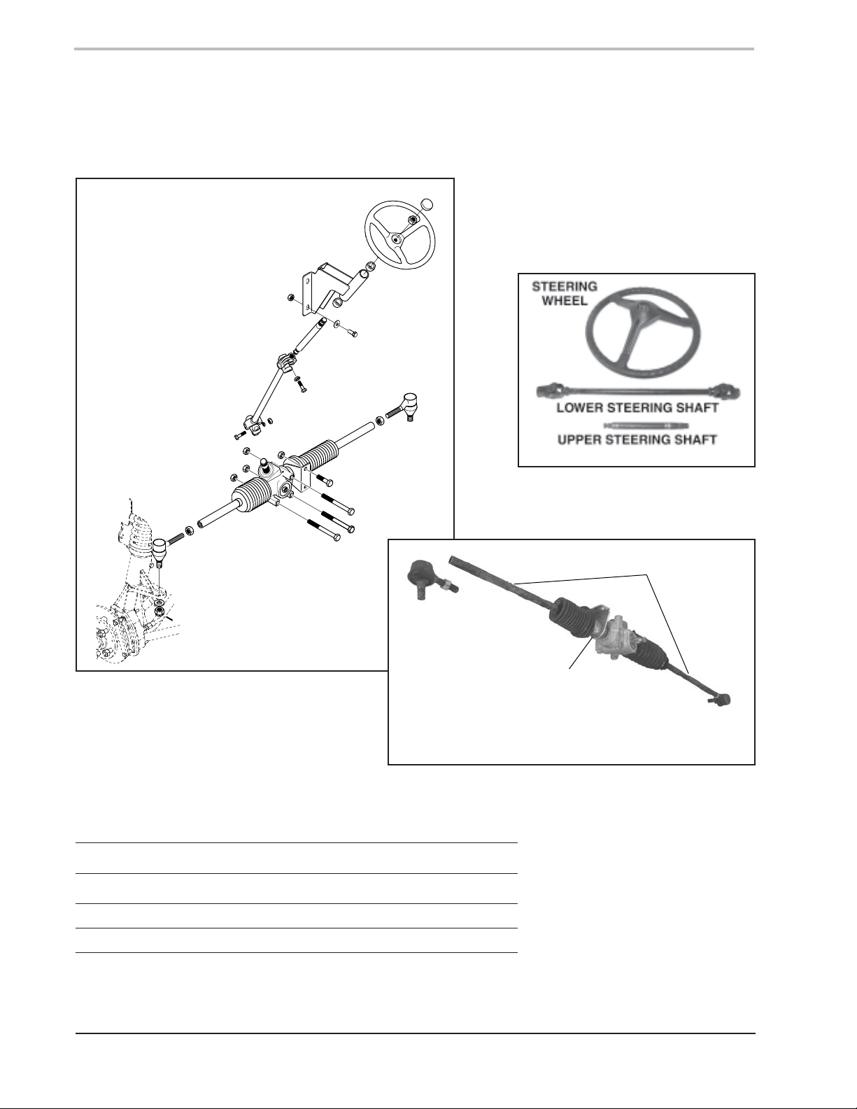
SPECIFICATIONS
TYPE: RACK AND PINION
STEERING
WHEEL
STEERING
SHAFT
BRACKET
STEERING
SHAFT
ASSEMBLY
TIE ROD
END
TIE ROD
END
Steering Assembly
TORQUE SPECIFICATIONS:
RACK & PINION
ASSEMBLY
TIE ROD
Steering Wheel and Shaft
RACK
LEFT
END
RIGHT
SIDE
BRACKET
RIGHT
TIE ROD
END
Rack, Pinion and Tie Rod Ends
COMPONENT TORQUE
Tie Rod End Slotted Nut 30 lbs. ft. (41 Nm)
Lug Nuts 50 lbs. ft. (68 Nm)
7-2
Page 3
BUSH HOG® UTILITY VEHICLE WORKSHOP MANUAL – SECTION 7: STEERING SYSTEM
TOOLS
Common hand and shop tools can be used to remove and install
steering system components serviced in the section. All special
tools are listed below.
Ball Joint Removal Tool (1.0-1.5” (25.4-38.1mm): Needed for
removal of tie rod ends from the strut casting steering arm. Ball joint
removal tools are commercially available in various sizes.
SAFETY FIRST
CAUTION
Never work underneath a raised vehicle without adequate support. Use jack stands
to prevent the vehicle from falling. A falling vehicle can cause severe personal
injury or death.
CAUTION
When lifting a vehicle chock the wheels left on the ground to prevent the vehicle
from rolling or sliding backward.
7-3
Page 4
BUSH HOG® UTILITY VEHICLE WORKSHOP MANUAL – SECTION 7: STEERING SYSTEM
DESCRIPTION
STEERING
The UTV rack and pinion steering (Figure 1) is common in many
automotive systems. The rack is a flat gear that extends outward
from both ends of the assembly. A tie rod end connects the rack to
the suspension strut assembly.
NOTICE: The suspension struts are described in the Suspension
Section of this manual.
The pinion is a rotary gear attached to the steering shaft assembly.
When the operator rotates the steering wheel the steering shaft turns
the pinion gear which drives the rack in a back and forth movement.
The rack and pinion gear set converts rotary steering wheel motion
into linear motion needed to turn the wheels. The rack and pinion
also provides gear reduction making it easier to steer the machine.
The tie rods connect to a steering arm on the struts used for turning
the strut. The wheels and hubs are mounted to the strut. See the
section entitled Suspension for a description of the strut assemblies.
TIE ROD
END
LOCK
NUT
LOCK
NUT
TIE ROD
END
PINION
GEAR
DRIVE
RACK
Figure 1
Rack and Pinion Assembly
7-4
Page 5

BUSH HOG® UTILITY VEHICLE WORKSHOP MANUAL – SECTION 7: STEERING SYSTEM
REPAIR
INSPECTION
See the operator’s manual for recommendations on inspecting the steering system.
Complaints of steering wheel hard to turn, hard steering, or loose steering can be a result of a bad
pinion gear, bad rack, or bad tie rod ends.
Use the recommendations in the operator’s manual for initial testing. Inspect the rack and pinion and
tie rods for worn, loose, or damaged parts.
Check for excessive wear in the steering bracket and upper steering shaft. Inspect the upper and lower
steering shaft U-joints for excessive wear and damage. Replace the steering bracket bushings, steering
bracket, upper and lower steering shafts as needed.
REMOVAL
CAUTION
When working underneath a raised vehicle, always support the vehicle with jack
stands to prevent the vehicle from falling. A falling vehicle can cause severe
personal injury or death.
RACK AND PINION REMOVAL
1. Using a floor jack, lift the machine and support with jack stands.
TIE ROD END
2. Turn the steering tires all the way right.
3. Remove the cotter pin from both tie rod end slotted hex nuts.
Discard cotter pins.
4. Remove both tie rod slotted hex nuts (Figure 2).
SLOTTED HEX NUT
Figure 2
Tie Rod End
7-5
Page 6

BUSH HOG® UTILITY VEHICLE WORKSHOP MANUAL – SECTION 7: STEERING SYSTEM
NOTICE: Place the ball joint tool between the tie rod end rubber
boot and the low side of the steering arm. Drive the tool into the joint
breaking the tie rod end loose from the steering arm.
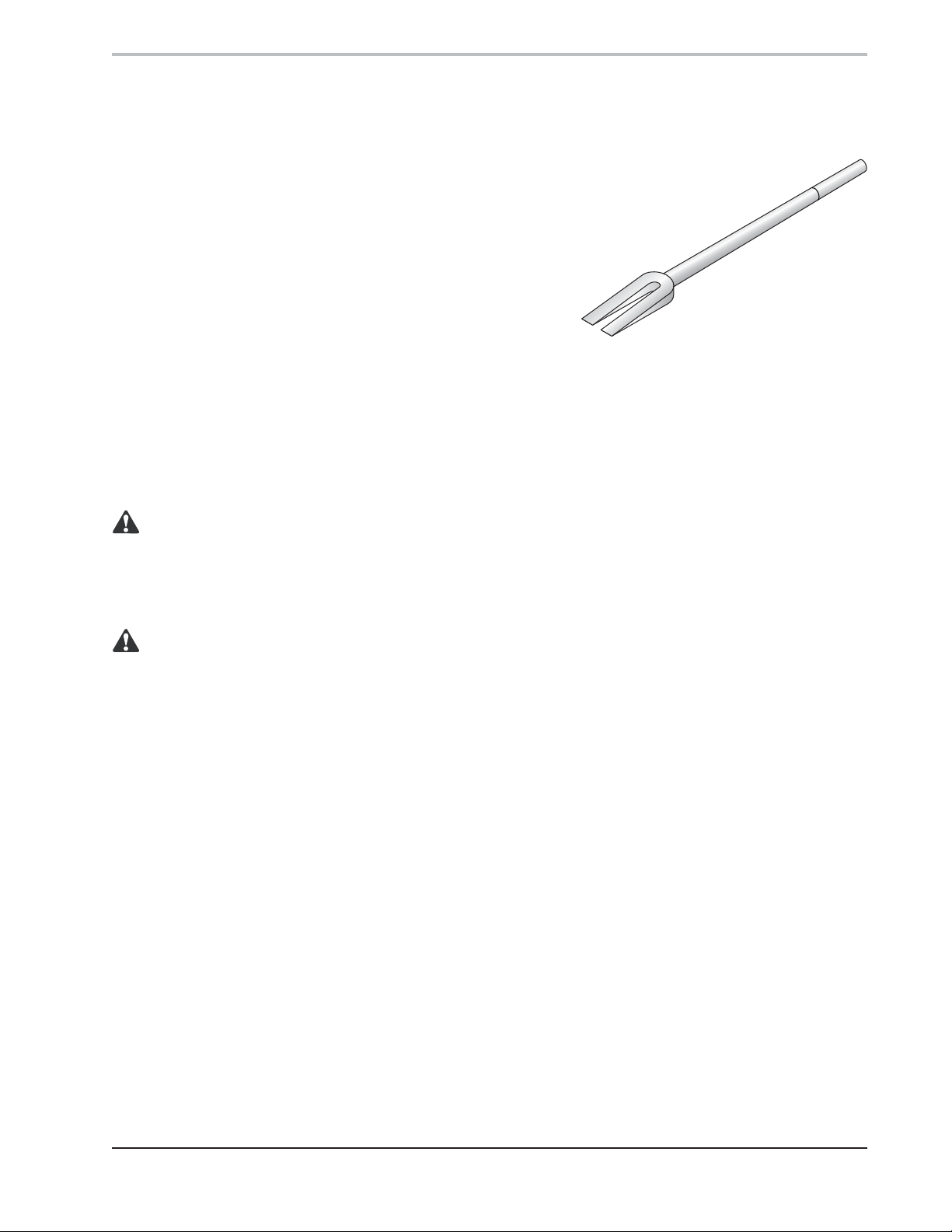
5. Using a ball joint tool (Figure 3) remove tie rod ends from the struts.
6. Loosen the tie rod end lock nuts (Figure 4).
BALL JOINT TOOL
TIE ROD END
Figure 3
Ball Joint Removal Tool
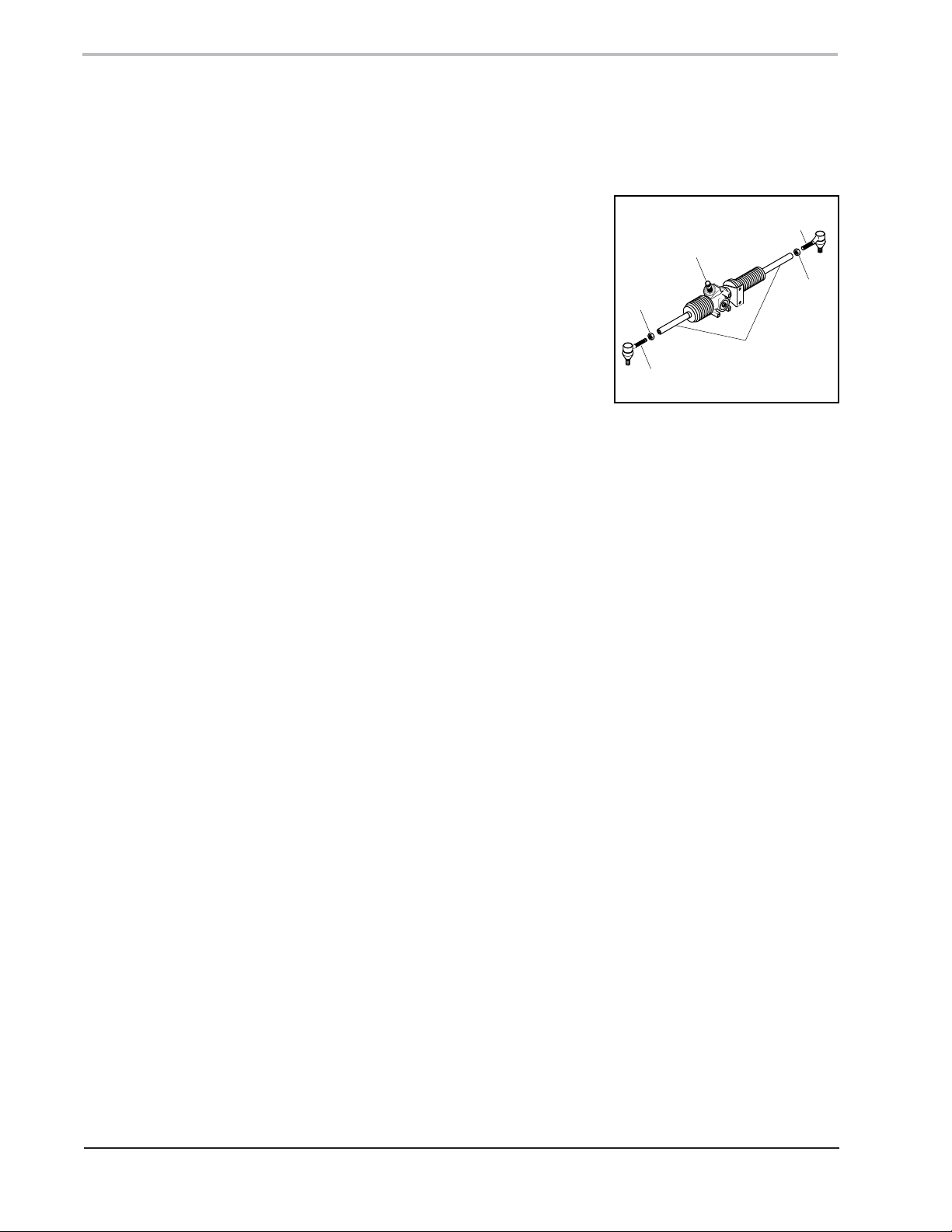
TIE ROD
END
7. Unscrew the tie rod ends (Figure 5) while counting each
revolution of the tie rod end. Note the total number of revolutions
required to remove the tie rod end from the rack.
8. Remove the hex head capscrew (Figure 5), nut, and lock
washer securing the lower steering shaft U-joint to the rack
and pinion assembly.
LOCK
NUT
Figure 4
Tie Rod End Removal
LOWER U-JOINT CAPSCREW
PINION INPUT
SHAFT
LOWER U-JOINT
CLAMP
Figure 5
Rack and Pinion Assembly
7-6
Page 7

BUSH HOG® UTILITY VEHICLE WORKSHOP MANUAL – SECTION 7: STEERING SYSTEM
9. Remove three capscrews and hex nuts securing the rack and
pinion assembly (Figure 6) to the frame support.
10. Remove two capscrews and lock nuts securing the right side
rack bracket (Figure 6) to the machine frame.
11. Disconnect the shifting cable from the shifting arm (Figure 7).
BRACKET & CAPSCREWS
CAPSCREWS
Figure 6
Rack and Pinion Assembly
SHIFTING ARM
12. Loosen the shifting cable housing lock nuts just enough to
remove the housing from the bracket (Figure 8).
13. Carefully remove the rack and pinion from machine.
14. Place the rack and pinion assembly on a work bench.
SHIFTING CABLE
Figure 7
Shifting Cable Linkage
SHIFTING CABLE
SHIFTING CABLE HOUSING
Figure 8
Shifting Cable Housing
7-7
Page 8

BUSH HOG® UTILITY VEHICLE WORKSHOP MANUAL – SECTION 7: STEERING SYSTEM
STEERING WHEEL REMOVAL
1. Turn the steering wheel for access to the upper steering shaft Ujoint capscrew (Figure 9).
2. Remove capscrew and lock washer from the upper U-joint clamp.
3. Pull the steering wheel and upper steering shaft out from the top.
4. Remove the hub from the center of the steering wheel.
5. Remove the hex nut securing the steering wheel to the upper shaft.
6. Using a press with a brass insert, press the upper shaft free from
the steering wheel.
STEERING SHAFT REMOVAL
1. Turn the steering shaft for access to the upper steering shaft
U-joint (Figure 10).
2. Using the section entitled Removal – Steering Wheel, remove the
steering wheel.
CAPSCREW
Figure 9
Upper Steering Shaft
U-joint
3. Remove two capscrews and lock nuts securing the steering joint
cover to the firewall (Figure 11).
4. Remove the steering joint cover.
5. Remove the capscrew, lock washer, and nut securing the lower
steering shaft U-joint to the rack and pinion assembly.
6. Remove the lower steering shaft from the rack and pinion assembly.
Figure 10
Upper Steering Shaft
U-joint
LOWER STEERING JOINT
STEERING JOINT COVER
Figure 11
Steering Joint Cover
7-8
Page 9

BUSH HOG® UTILITY VEHICLE WORKSHOP MANUAL – SECTION 7: STEERING SYSTEM
TIE ROD
END
LOCK
NUT
INSTALLATION
CAUTION
When working underneath a raised vehicle, always support the vehicle with jack
stands to prevent the vehicle from falling. A falling vehicle can cause severe
personal injury or death.
RACK AND PINION INSTALLATION
1. Position the rack and pinion assembly against the firewall for
installation.
2. Using the note indicating the number of turns required to unscrew
the tie rod ends; install the tie rod ends the same number of
revolutions (Figure 12).
3. Securely tighten the tie rod end lock nuts.
4. Position the rack and pinion assembly with the tie rod ends
resting in the strut steering arms.
NOTICE: The rack and pinion shaft can only be installed in one
position, one spline on the shaft is wider than the others and
must be aligned with the wider slot in the U-joint.
5. Install the pinion assembly into the lower steering shaft U-joint.
Secure the U-joint and pinion input shaft with a capscrew, lock
washer and hex nut. Tighten nut securely.
6. Install three capscrews and hex nuts securing the rack and
pinion assembly to the fire wall (Figure 13). Tighten securely.
7. Install two capscrews through the right side rack extension
bracket and frame support. Secure the bracket with two hex
nuts. Tighten securely.
8. Install a slotted nut on both tie rod ends. Tighten the nuts to 30
lbs. ft. (41 Nm) then back off to the first through slot.
9. Install and lock a new cotter pin in each slotted nut and tie rod end.
Figure 12
Tie Rod Installation
CAPSCREWS
Figure 13
Rack and Pinion
7-9
Page 10

BUSH HOG® UTILITY VEHICLE WORKSHOP MANUAL – SECTION 7: STEERING SYSTEM
10. Place the shifting cable housing on the mounting bracket with a
lock washer on each side of the bracket (Figure 14).
11. Tighten shifting cable housing nuts (Figure 14) securely.
12. Connect the shifting cable to the shifting arm. Tighten nut to
general torque specifications.
STEERING SHAFT INSTALLATION
NOTICE: The rack and pinion shaft can only be installed in one
position, one spline on the shaft is wider than the others and must
be aligned with the wider slot in the U-joint.
1. Position the lower steering shaft with the lower U-joint installed
on the pinion input shaft. Secure with a capscrew, lock washer
and hex nut. Tighten hex nut securely.
2. Install the steering joint cover over the bottom of the lower
steering shaft and align with mounting holes on the firewall.
Secure joint cover with two capscrews and lock nuts. Tighten
lock nuts securely.
LOCK WASHER
LOCK WASHER
Figure 14
Shifting Cable Housing
3. Using the section entitled Installation – Steering Wheel install
the steering wheel on the end of the upper steering shaft.
STEERING WHEEL INSTALLATION
1. Install the upper steering shaft through the steering bracket and
into the top of the upper steering shaft U-joint (Figure 15).
2. Install a capscrew and lock washer through the upper U-joint
clamp. Tighten securely.
3. Position the steering wheel on the end of the upper steering shaft
in the desired position. Secure steering wheel with hex nut.
Tighten hex nut securely.
4. Install hub in the center of the steering wheel.
Figure 15
Upper U-joint
7-10
Page 11

BUSH HOG® UTILITY VEHICLE WORKSHOP MANUAL – SECTION 7: STEERING SYSTEM
ADJUSTMENT
The UTV steering alignment can be checked for proper forward travel
by measuring (Figure 16) between the front center of the right
steering tire and left steering tire.
• Make note of the distance.
• Next measure between the rear center of the right steering tire
and the rear left steering tire. Make note of the distance.
• Compare the measurements of the center tire spread front and
rear. The measurement should be within 1/4".
CAUTION
When adjusting steering, compensation should not be
made for tire or rim deformities. Deformed tires or
wheels should be replaced to provide safe steering
and vehicle operation.
Adjustment can be made by removing the tie rod ends from the strut
steering arms.
FRONT
REAR
Figure 16
Steering Tire Alignment
1. Remove the tie rod ends slotted nut and cotter pin. Discard
cotter pin.
2. Use a ball joint removal tool to remove the tie rod end from the
strut. See the section entitled Removal – RACK AND PINION.
3. Loosen the tie rod end lock nuts.
4. Tighten or loosen the tie rod ends (Figure 17) in the rack to align the
steering tires. Secure the tie rod ends by tightening the lock nuts.
5. Position tie rod ends in the strut steering arms. Secure tie rod
ends with slotted nuts. Tighten nuts securely and back off to first
through hole in the nut and tie rod end. Install and lock new
cotter pins in each tie rod end.
6. Remove jack stands and lower vehicle. Perform steering
inspection as outlined in the operator’s manual.
Figure 17
Strut and Tie Rod End
7-11
 Loading...