

Page 1
BUSH HOG
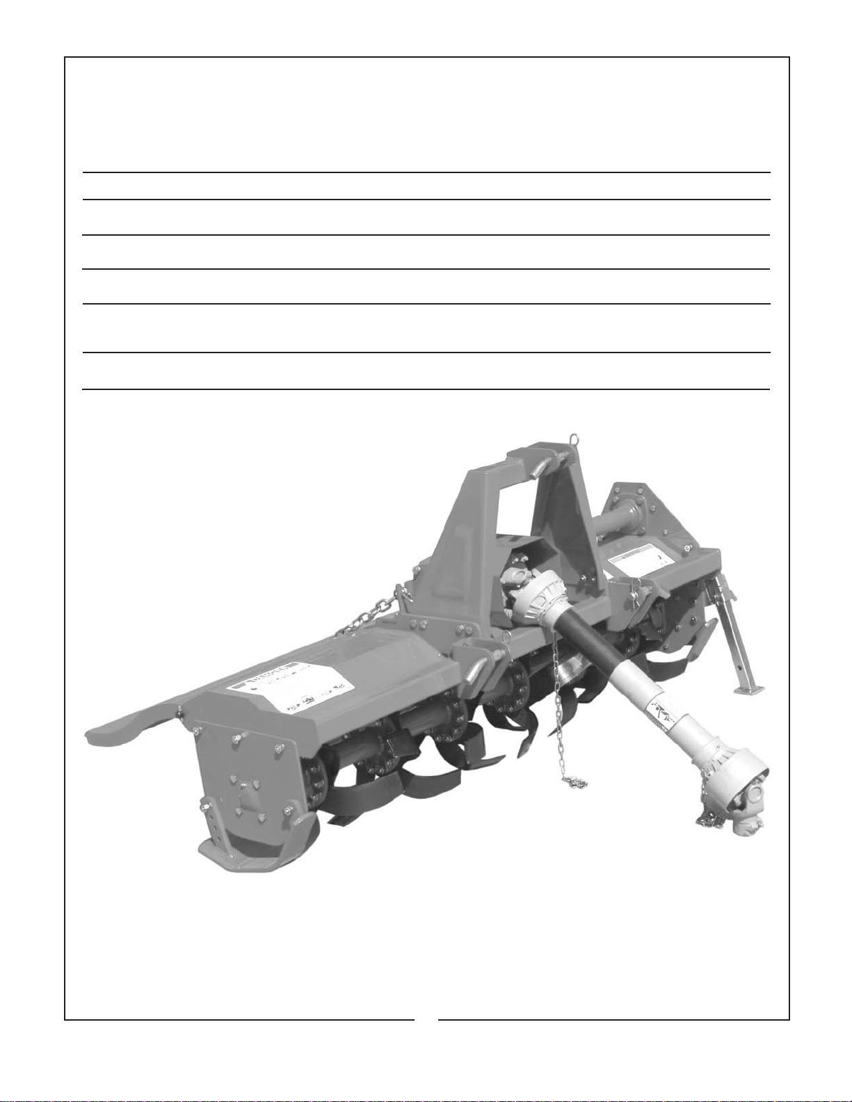
MODEL RTC
RRoottaarryy TTiilllleerr
®
ASSEMBLY
107 $4.00
ll
OPERATION
ll
MAINTENANCE
50047335
Page 2

CONGRATULATIONS!
You have invested in the best implement of its type on the market today.
The care you give your Bush Hog implement will greatly determine your satisfaction
with its performance and its service life. We urge a careful study of this manual to provide
you with a thorough understanding of your new implement before operating, as well as
suggestions for operation and maintenance.
If your manual should become lost or destroyed, Bush Hog will be glad to provide you with
a new copy. Order from Bush Hog, P. O. Box 1039, Selma, Alabama 36702-1039. Most of
our manuals can also be downloaded from our website at www.bushhog.com.
As an authorized Bush Hog dealer, we stock genuine Bush Hog parts which are
manufactured with the same precision and skill as our original equipment. Our trained
service personnel are well informed on methods required to service Bush Hog equipment,
and are ready and able to help you.
Should you require additional information or assistance, please contact us.
YOUR AUTHORIZED
BUSH HOG DEALER
BECAUSE BUSH HOG MAINTAINS AN ONGOING
PROGRAM OF PRODUCT IMPROVEMENT, WE
RESERVE THE RIGHT TO MAKE IMPROVEMENTS IN
DESIGN OR CHANGES IN SPECIFICATIONS WITHOUT INCURRING ANY OBLIGATION TO INSTALL
THEM ON UNITS PREVIOUSLY SOLD.
BECAUSE OF THE POSSIBILITY THAT SOME
PHOTOGRAPHS IN THIS MANUAL WERE TAKEN OF
PROTOTYPE MODELS, PRODUCTION MODELS MAY
VARY IN SOME DETAIL. IN ADDITION, SOME
PHOTOGRAPHS MAY SHOW SHIELDS REMOVED
FOR PURPOSES OF CLARITY. NEVER OPERATE
THIS IMPLEMENT WITHOUT ALL SHIELDS IN PLACE.
Page 3

Model RTC
Rotary Tiller Operator’s Manual
TABLE OF CONTENTS
SECTION / PARA PAGE
Warranty . . . . . . . . . . . . . . . . . . . . . . . .2
Dealer Preparation Check List . . . . . . .3
Safety Precautions . . . . . . . . . . . . . . . .4
Federal Laws And Regulations . . . . . .5
I INTRODUCTION & DESCRIPTION . . .6
1-1 Introduction . . . . . . . . . . . . . . . . . .6
1-2 Description . . . . . . . . . . . . . . . . . . .6
II PREPARATION FOR USE . . . . . . . . .7
2-1 Attaching To Tractor . . . . . . . . . . .7
III OPERATING INSTRUCTIONS . . . . . .9
3-1 General Safety . . . . . . . . . . . . . . . .9
3-2 Adjusting For Work . . . . . . . . . . . .9
RETAIL CUSTOMER’S RESPONSIBILITY
SECTION / PARA PAGE
3-3 Operation . . . . . . . . . . . . . . . . . . . .9
3-4 Transporting . . . . . . . . . . . . . . . . . .9
IV MAINTENANCE . . . . . . . . . . . . . . . . .10
4-1 Maintenance Check List . . . . . . . .10
4-2 Lubrication . . . . . . . . . . . . . . . . . .10
4-3 Blade Replacement . . . . . . . . . . .12
4-4 Slip Clutch Operational Check . . .12
4-5 Slip Clutch Adjustment . . . . . . . . .12
4-7 Troubleshooting . . . . . . . . . . . . . .13
V DEALER ASSEMBLY . . . . . . . . . . . . .14
Safety Decals . . . . . . . . . . . . . . . . . . .16
Torque Specifications . . . . . . . . . . . . .17
UNDER THE BUSH HOG WARRANTY
It is the Retail Customer and/or Operator’s responsibility to read the Operator’s Manual, to
operate, lubricate, maintain and store the product in accordance with all instructions and
safety procedures. Failure of the operator to read the Operator’s Manual is a misuse of this
equipment.
It is the Retail Customer and/or Operator’s responsibility to inspect the product and to have
any part(s) repaired or replaced when continued operation would cause damage or excessive wear to other parts or cause a safety hazard.
It is the Retail Customer’s responsibility to deliver the product to the authorized Bush Hog
Dealer, from whom he purchased it, for service or replacement of defective parts which are
covered by warranty. Repairs to be submitted for warranty consideration must be made within forty-five (45) days of failure.
It is the Retail Customer’s responsibility for any cost incurred by the Dealer for traveling to or
hauling of the product for the purpose of performing a warranty obligation or inspection.
1
Page 4

LIMITED WARRANTY
OOOOOOOOOOOOOOOOOOOOOOOOOOOOOOO
Bush Hog warrants to the original purchaser of any new Bush Hog equipment, purchased from an
authorized Bush Hog dealer, that the equipment be free from defects in material and workmanship for a period
of one (1) year for non-commercial, state, and municipalities’ use and ninety (90) days for commercial use from
date of retail sale. The obligation of Bush Hog to the purchaser under this warranty is limited to the repair or
replacement of defective parts.
Replacement or repair parts installed in the equipment covered by this limited warranty are warranted
for ninety (90) days from the date of purchase of such part or to the expiration of the applicable new equipment warranty period, whichever occurs later. Warranted parts shall be provided at no cost to the user at an
authorized Bush Hog dealer during regular working hours. Bush Hog reserves the right to inspect any equipment or parts which are claimed to have been defective in material or workmanship.
DISCLAIMER OF IMPLIED WARRANTIES & CONSEQUENTIAL DAMAGES
Bush Hog’s obligation under this limited warranty, to the extent allowed by law, is in lieu of all war-
ranties, implied or expressed, INCLUDING IMPLIED WARRANTIES OF MERCHANTABILITY AND FITNESS
FOR A PARTICULAR PURPOSE and any liability for incidental and consequential damages with respect to
the sale or use of the items warranted. Such incidental and consequential damages shall include but not be limited to: transportation charges other than normal freight charges; cost of installation other than cost approved
by Bush Hog; duty; taxes; charges for normal service or adjustment; loss of crops or any other loss of income;
rental of substitute equipment, expenses due to loss, damage, detention or delay in the delivery of equipment
or parts resulting from acts beyond the control of Bush Hog.
THIS LIMITED WARRANTY SHALL NOT APPLY:
1. To vendor items which carry their own warranties, such as engines, tires, and tubes.
2. If the unit has been subjected to misapplication, abuse, misuse, negligence, fire or other accident.
3. If parts not made or supplied by Bush Hog have been used in connection with the unit, if, in the sole judgement of Bush Hog such use affects its performance, stability or reliability.
4. If the unit has been altered or repaired outside of an authorized Bush Hog dealership in a manner
which, in the sole judgement of Bush Hog, affects its performance, stability or reliability.
5. To normal maintenance service and normal replacement items such as gearbox lubricant, hydraulic fluid,
worn blades, or to normal deterioration of such things as belts and exterior finish due to use or
exposure.
6. To expendable or wear items such as teeth, chains, sprockets, belts, springs and any other items that in the
company’s sole judgement is a wear item.
NO EMPLOYEE OR REPRESENTATIVE OF BUSH HOG IS AUTHORIZED TO CHANGE THIS LIMITED WARRANTY IN ANY WAY OR GRANT ANY OTHER WARRANTY UNLESS SUCH CHANGE IS MADE
IN WRITING AND SIGNED BY BUSH HOG’S SERVICE MANAGER, POST OFFICE BOX 1039, SELMA,
ALABAMA 36702-1039.
OOOOOOOOOOOOOOOOOOOOOOOOOOOOOOO
Record the model number, serial number and date
purchased. This information will be helpful to your
dealer if parts or service are required.
MAKE CERTAIN THE WARRANTY REGISTRATION
CARD HAS BEEN FILED WITH BUSH HOG/
SELMA, ALABAMA
MODEL NUMBER
SERIAL NUMBER
DATE OF RETAIL SALE
2
Page 5

DEALER PREPARATION CHECK LIST
ROTARY TILLERS
BEFORE DELIVERING MACHINE — The following check list should be completed.
Use the Operator’s Manual as a guide.
r 1. Assembly completed.
r 2. Gearboxes filled with oil.
r 3. All fittings lubricated.
r 4. All shields in place and in good condition.
r 5. All fasteners torqued to specifications given in Torque Chart.
r 6. Slip clutch checked for proper operation.
r 7. All decals in place and readable. (See decal page.)
r 8. Overall condition good (i.e. paint, welds)
r 9. Operators manual has been delivered to owner and he has been instructed
on the safe and proper use of the cutter.
Dealer’s Signature
Purchaser’s Signature
THIS CHECKLIST TO REMAIN IN OWNER’S MANUAL
It is the responsibility of the dealer to complete the procedures listed
above before delivery of this implement to the customer.
3
Page 6

IMPORTANT SAFETY PRECAUTIONS
This symbol is used to call attention to safety precautions that should be followed by
the operator to avoid accidents. When you
see this symbol, carefully read the message
that follows and heed its advice. Failure to
comply with safety precautions could result
in serious bodily injury.
In addition to the design and configuration of equipment, hazard control and accident prevention are dependent upon the awareness, concern, prudence and proper training of personnel in the operation, transport,
maintenance and storage of equipment. Lack of attention to safety can result in accident, personal injury,
reduction of efficiency and worst of all—loss of life. Watch for safety hazards and correct deficiencies
promptly. Use the following safety precautions as a general guide to safe operations when using this
machine. Additional safety precautions are used throughout this manual for specific operating and mainte
nance procedures. Read this manual and review the safety precautions often until you know the limitations.
1. Read the Operator’s Manual. Failure to read the Operator’s Manual is considered a misuse of this
equipment.
2. Become familiar with all the machine’s controls and all the caution, warning and danger decals
affixed to the machine before attempting to start or operate.
3. Before starting or operating the machine, make a walk around inspection and check for obvious
defects such as loose mounting bolts and damaged components. Correct any deficiency before
starting.
4. Do not allow children to operate the implement. Do not allow adults to operate it without proper
instruction.
5. Do not carry passengers.
6. Keep the area of operation clear of all persons, particularly small children and pets. The operator
should cease operation whenever anyone comes within the area.
7. Lower implement to ground, stop tractor engine and apply parking brake before leaving the tractor.
8. Keep hands and feet away from implement.
9. Wear personal protective equipment such as, but not limited to, protection for eyes, ears, feet,
hands and head when operating or repairing the equipment. Do not wear loose clothing or jewelry
that may catch on equipment moving parts.
10. When performing adjustments or maintenance on the implement, first lower it to the ground or block
it securely at a workable height.
11. Never stand between tractor and implement while tractor is being backed to the hitch.
12. Reduce speed when transporting implement to avoid bouncing and momentary loss of steering.
13. Use tractor flashing warning lights, day or night, when transporting implement on road or highways
unless prohibited by law.
14. Use a rollover protective structure and seat belt equipped tractor for all implement operations.
4
Page 7

IMPORTANT FEDERAL LAWS AND REGULATIONS* CONCERNING
EMPLOYERS, EMPLOYEES AND OPERATIONS.
*(This section is intended to explain in broad terms the concept and effect of the following federal laws and
regulations. It is not intended as a legal interpretation of the laws and should not be considered as such).
U.S. Public Law 91-596 (The Williams-Steiger Occupational and Health Act of 1970) OSHA
This Act Seeks:
“...to assure so far as possible every working man and woman in the nation safe and healthful working
conditions and to preserve our human resources...”
DUTIES
Sec. 5 (a) Each employer—
(1) shall furnish to each of his employees employment and a place of employment
which are free from recognized hazards that are causing or are likely to cause
death or serious physical harm to his employees;
(2) shall comply with occupational safety and health standards promulgated under
this Act.
(b) Each employee shall comply with occupational safety and health standards
and all rules, regulations and orders issued pursuant to this Act which are
applicable to his own actions and conduct.
OSHA Regulations
Current OSHA regulations state in part: “At the time of initial assignment and at least annually thereafter, the
employer shall instruct every
employee is, or will be involved.” These will include (but are not limited to) instructions to:
employee in the safe operation and servicing of all equipment with which the
Keep all guards in place when the machine is in operation;
Permit no riders on equipment;
Stop engine, disconnect the power source, and wait for all machine movement to stop before
servicing, adjusting, cleaning or unclogging the equipment, except where the machine must be
running to be properly serviced or maintained, in which case the employer shall instruct employees
as to all steps and procedures which are necessary to safely service or maintain the equipment.
Make sure everyone is clear of machinery before starting the engine, engaging power, or operating
the machine.
EMPLOYEE TRACTOR OPERATING INSTRUCTIONS:
1. Securely fasten your seat belt if the tractor has a
ROPS.
2. Where possible, avoid operating the tractor near
ditches, embankments, and holes.
3. Reduce speed when turning, crossing slopes, and
on rough, slick, or muddy surfaces.
4. Stay off slopes too steep for safe operation.
5. Watch where you are going, especially at row
ends, on roads, and around trees.
6. Do not permit others to ride.
7. Operate the tractor smoothly - no jerky turns,
starts, or stops.
8. Hitch only to the drawbar and hitch points recom-
mended by tractor manufacturers.
9. When tractor is stopped, set brakes securely and
use park lock if available.
Child Labor Under 16 Years Old
Some regulations specify that no one under the age of 16 may operate power machinery. It is your
responsibility to know what these regulations are in your own area or situation. (Refer to U.S. Dept. of
Labor, Employment Standard Administration, Wage & Home Division, Child Labor Bulletin #102.)
5
Page 8
SECTION l
INTRODUCTION AND DESCRIPTION
1-1 INTRODUCTION
We are pleased to have you as a Bush Hog customer.
Your Bush Hog Rotary Tiller has been carefully
designed to give maximum service with minimum
down time. This manual is provided to give you the
necessary operating and maintenance instructions
for keeping your rotary tiller in top operating condition. Please read this manual thoroughly.
Understand what each control is for and how to use
it. Observe all safety precautions decaled on the
machine and noted throughout the manual for safe
operation of the implement. If any assistance or additional information is needed, contact your authorized
Bush Hog dealer.
NOTE
All references made in this manual to right, left, front,
rear, top and bottom is as viewed facing the direction
of forward travel with implement properly attached to
tractor.
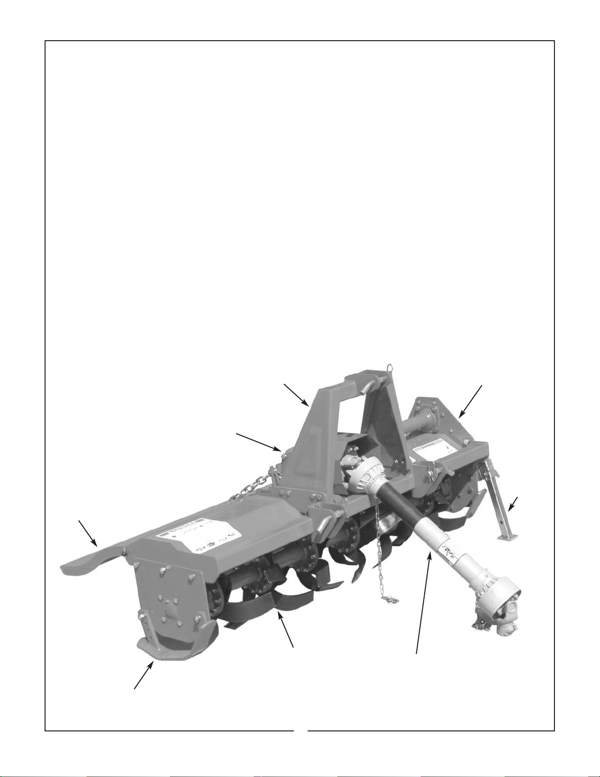
Figure 1-1 Major Components
A-Frame
1-2 DESCRIPTION
The RTC series of rotary tillers are intended for light
duty use in an environment relatively clean of foreign objects such as large rocks, etc. Each tiller is
equipped with adjustable skid shoes and rear deflector shield for setting the desired operating depth and
tilth of soil. The drivetrain consists of a telescoping
input driveshaft; 90 degree transfer gearbox, crossshaft and chain drive rotor. Protection is provided by
a slip clutch on the driveline. The chain is selfadjusted by a spring tension device. Major components are identified in Figure 1-1.
Chain Drive Cover
(Behind End Plate)
Rear
Deflector
Adjustable Skid Shoe
Input Gearbox
Rotor/Blade Assembly
Parking
Stand
Driveline With Slip Clutch
6
Page 9
SPECIFICATIONS
Model RTC40 Model RTC48
Tilling width 39-1/4” 48-1/4”
Overall width 44” 53”
Offset 4” N/A
Blades per flange 44
No. of flanges 45
Hitch 3-point Cat. I only
PTO speed 540 rpm
Rotor speed 250 rpm
Max. recommended HP 24
Max. till depth 6”
Gearbox oil capacity 17 ozs.
Weight 308 lbs. 335 lbs.
Driveline protection Slip Clutch
SECTION II
PREPARATION FOR USE
2-1 ATTACHING TO TRACTOR
WARNING
TO AVOID SERIOUS INJURY OR DEATH:
NEVER STAND BETWEEN TRACTOR
AND TILLER WHILE TRACTOR IS BEING
BACKED TO HITCH.
WARNING
TO AVOID SERIOUS INJURY OR DEATH:
ADDITIONAL TRACTOR FRONT BAL-
LAST MAY BE NEEDED FOR STABLE
OPERATION AND TRANSPORT OF THE
TILLER. SEE TRACTOR OPERATOR’S
MANUAL FOR RECOMMENDEDWEIGHTS.
A. Attach tiller to tractor 3-point hitch per tractor
operator’s manual. Do not attach driveline at this
time.
NOTE
Due to the many variations in tractor/implement hitch
points and corresponding differences in distances
between tractor PTO shafts and implement input
shafts, drivelines may need to be shortened as
described in the following steps:
B. Raise and lower tiller to determine position
with shortest distance between the tractor PTO shaft
and gearbox input shaft. Shut down tractor, leaving
tiller in position of shortest distance. Securely block
tiller in position.
C. Pull driveline apart. Attach outer (female) section to tractor PTO shaft. Pull on driveline section to
be sure that yoke locks into place.
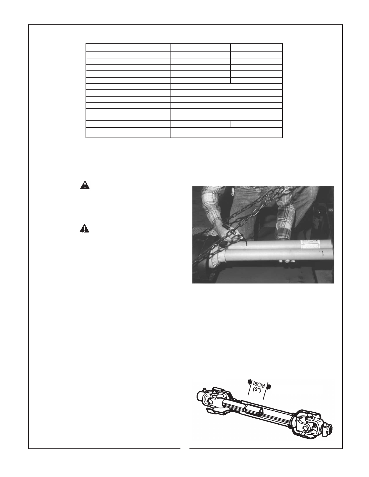
D. Hold driveline sections parallel to each other
to determine if it is too long. Each section should end
approximately 3 inches (76mm) short of reaching
universal joint shield on opposite section. If too long,
measure 3 inches back from universal joint shield
and mark on opposite section. (Figure 2-1). Do this
for both sections.
Figure 2-1
E. Raise and lower tiller to determine position
with greatest distance between PTO shaft and gearbox input shaft. Shut down tractor leaving tiller in
position of greatest distance. Securely block tiller
in position.
F. Hold driveline sections parallel to each other
and check for minimum 6 inches (15cm) overlap.
(Figure 2-2) If driveline has been marked for cutting,
overlap will be the distance between two marks. If
driveline has less than minimum overlap, do not use.
Contact authorized Bush Hog dealer.
Figure 2-2
Minimum Overlap
7
Page 10
NOTE
If driveline is the correct length, omit the following
steps “G” through “J” and proceed to step “K”.
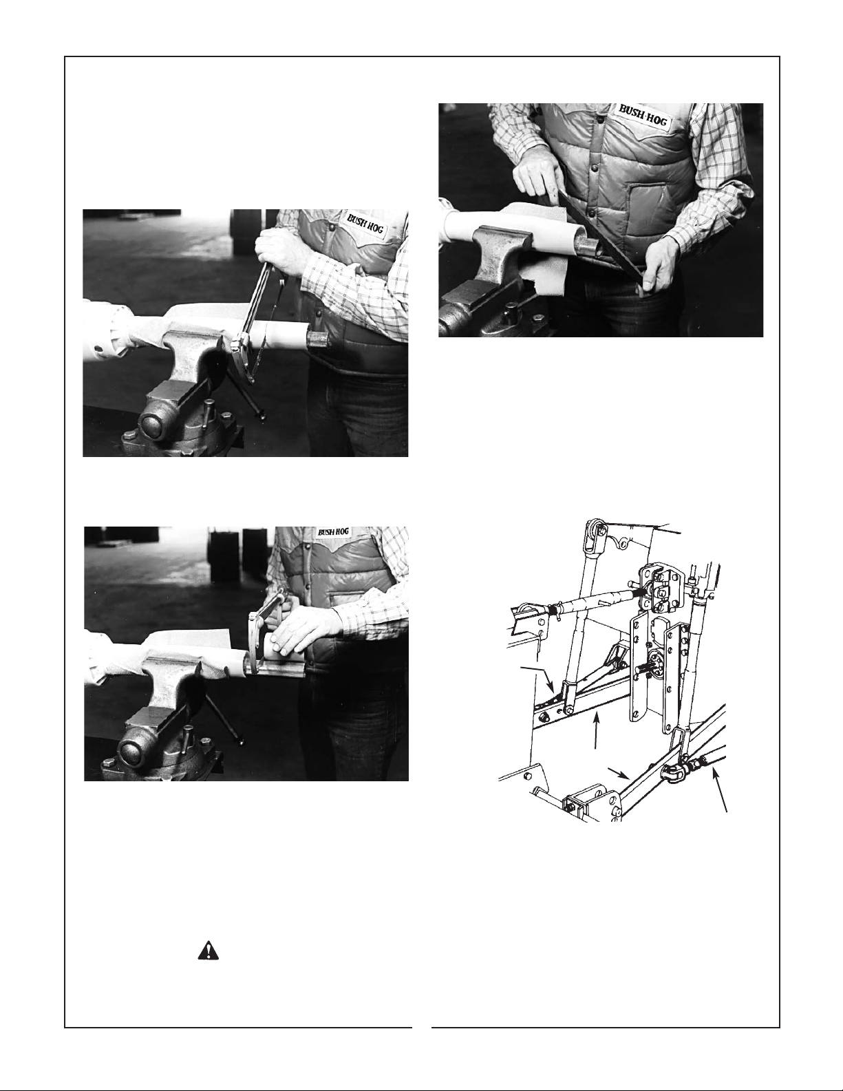
G. Clamp driveline in a well padded vice to prevent damage to the shield. Cut off shield where
marked. (Figure 2-3)
Figure 2-3
H. Using cut off section of shield as a guide, cut
shaft the same amount. (Figure 2-4)
Figure 2-4
Figure 2-5
L. Adjust lower lift arm to level tiller right to left.
Refer to tractor operator’s manual for instructions.
M. Adjust top link of tractor 3-point hitch to level
tiller front to rear.
N. Set up tractor stabilizer bars, sway blocks, or
equivalent to prevent implement side sway. (Figure 2-6)
Figure 2-6
Stabilizer Bars
I. Repeat steps “G” and “H” to other driveline
section.
J. Deburr ends of driveline sections and clean
away all chips and fillings. (Figure 2-5)
K. Apply multi-purpose grease to inside of outer
(female) driveline section. Assemble driveline and
install on tractor and tiller. Pull on each driveline section to be sure yokes lock into place. Make certaqin
driveline shielding is in place and in good condition.
DANGER
MAKE CERTAIN DRIVELINE YOKES ARE
SECURELY FASTENED. FAILURE TO DO SO
MAY RESULT IN SERIOUS INJURY.
Stabilizer
Lift Arms
Stabilizer
8
Page 11
SECTION III
OPERATING INSTRUCTIONS
3-1 GENERAL SAFETY
Only qualified people familiar with this operator’s
manual should operate this machine. Operator should
wear hard hat, safety glasses, and safety shoes. The
operator should read, understand and practice all
safety messages shown on the caution, warning, and
danger decals affixed to the tiller to avoid serious
injury or death. Use a rollover protective structure and
seatbelt equipped tractor for all operations. Before
beginning operation, clear work area of objects that
may be picked up and thrown or wrapped in tiller
blades. Check for ditches, stumps, holes, or other
obstacles that could upset tractor or damage tiller.
Always turn off tractor engine, set parking brake, and
allow rotor to come to a complete stop before dismounting tractor.
3-2 ADJUSTING FOR WORK
WARNING
THE TILLER CAN FALL FROM
HYDRAULIC SYSTEM FAILURE. TO
AVOID SERIOUS INJURY OR DEATH,
SECURELY SUPPORT TILLER BEFORE
WORKING UNDERNEATH.
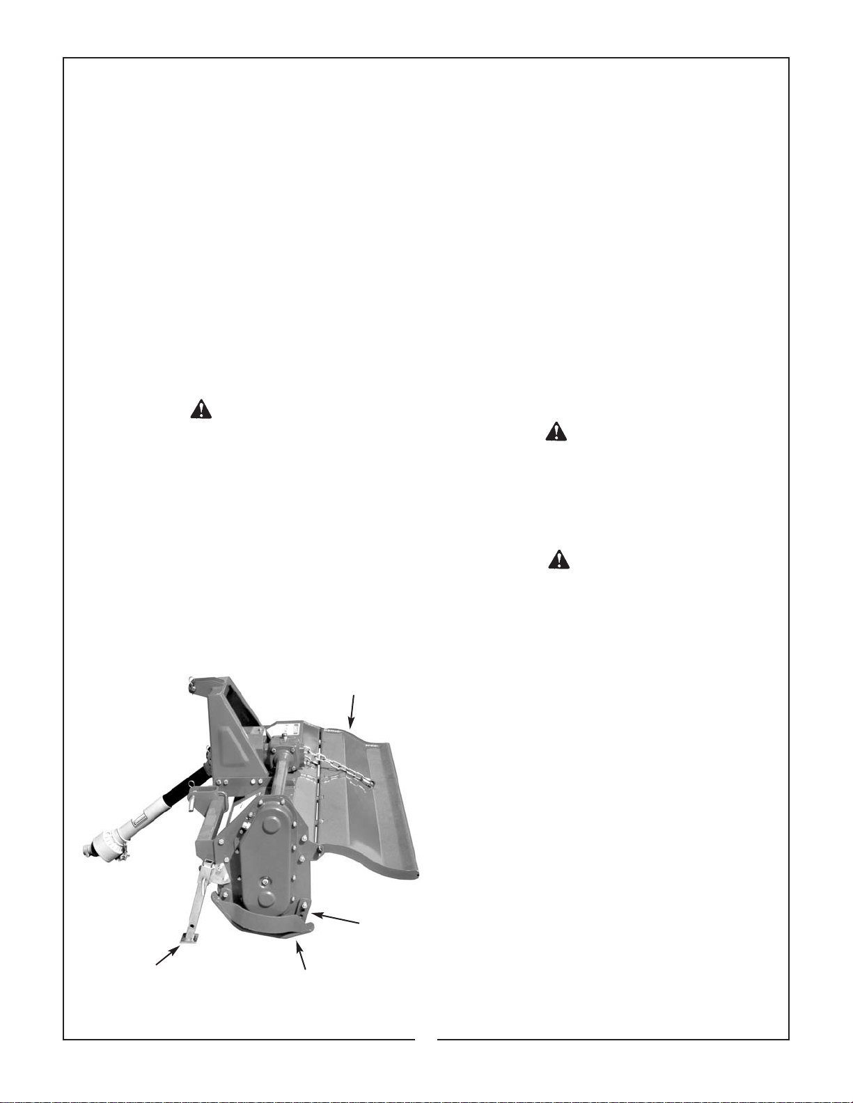
Depth of till is regulated by adjusting skids up or
down. (Figure 3-1) Average soil with reasonable
moisture will allow maximum depth in one pass with
a tractor forward speed up to 2 mph. Hard soil may
require two passes to reach maximum depth.
Figure 3-1 Adjustments
Rear Deflector
w/Adjusting Chain
Height
Adjuster
Parking Stand
Skid
Tractor forward speed and rear shield adjustment
(Figure 3-1) will regulate the finished results or tilth
of soil. Traveling at the slowest forward speed with
rear deflector fully lowered will give finest possible
finish. This deflector adjustment is good for
mulching, mixing, and burying weeds, fertilizer, etc.
The more you increase forward speed and deflector
height, the coarser the finished results will be. To
leave the ground surface rough with larger clods and
residue exposed, work with deflector fully raised.
When working in rocky soil, always have shield in
raised position.
3-3 OPERATION
A. Perform BEFORE EACH USE maintenance
listed in paragraph 4-1.
B. Adjust for work per paragraph 3-2.
C. Start tractor. Raise tiller off the ground.
D. With tractor at idle speed, engage PTO drive.
DANGER
STAY CLEAR OF ROTATING DRIVELINES.
DO NOT OPERATE WITHOUT DRIVELINE
SHIELDS IN PLACE AND IN GOOD CONDITION. FAILURE TO HEED THESE WARNINGS MAY RESULT IN PERSONAL INJURY
OR DEATH.
DANGER
KEEP HANDS AND FEET FROM UNDER
MACHINE AT ALL TIMES. MAKE CERTAIN
EVERYONE IS CLEAR OF MACHINE
BEFORE OPERATING. FAILURE TO HEED
THESE WARNINGS MAY RESULT IN PERSONAL INJURY OR DEATH.
E. Place tractor in gear and proceed forward.
Increase speed to 3/4 throttle. Lower tiller into soil.
Increase speed to 540 PTO rpm. Average soil with
reasonable moisture will allow travel speeds up to 2
mph. Hard soil will require low travel speed, less
than 1 mph to ensure smooth operation and maximum possible depth. Shallow weed cultivation will
allow speeds up to 3 mph. At the end of a pass lift
tiller clear of ground before making a turn. After turning, proceed back across field, slowly lowering the
tiller into the soil. Do not turn with tiller in the
ground as this can damage tiller and tractor linkage. Never use reverse gear while tiller is lowered into ground. Avoid operating tiller in the
raised position.
3-4 TRANSPORTING
Do not engage PTO drive while transporting tiller.
Obey all state and local laws when transporting on
public roads. Always use flashing warning lights
unless prohibited by law.
9
Page 12
SECTION IV
MAINTENANCE
4-1 MAINTENANCE CHECK LIST
Perform scheduled maintenance as outlined below.
Lower machine to ground, turn off tractor and set
parking brake before doing maintenance inspections
or work. Some checks may require raising machine
off ground and supporting with blocks. All bolts
should be torqued as recommended in TORQUE
SPECIFICATIONS, unless otherwise indicated.
BEFORE EACH USE
1. Check tractor tire air pressure. Refer to tractor
operator’s manual.
WARNING
THE TILLER CAN FALL FROM HYDRAULIC
SYSTEM FAILURE. TO AVOID SERIOUS
INJURY OR DEATH, SECURELY SUPPORT
TILLER BEFORE WORKING UNDERNEATH.
2. Check blades and rotor to be sure that no foreign
objects such as wire or steel strapping bands are
wrapped around them.
3. Check blade bolts for tightness. Tighten to
70 ft./lbs.
4. Inspect blades for wear. Replace if necessary.
5. Make certain driveline shields are in place and in
good repair.
6. Clean any debris from safety decals and check
for legibility. Replace any missing or illegible
decals. Read and heed safety messages.
7. Perform BEFORE EACH USE lubrication per
paragraph 4-2.
8. During operation, listen for abnormal sounds
which might indicate loose parts, damaged bear-
ings, or other damage.
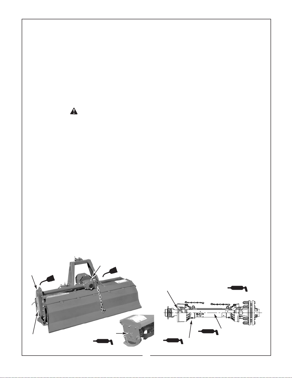
Figure 4-1
Lubrication
Chain Drive
Oil Filler Plug
(6) 50 Hours
(5) 50 Hours
AFTER EACH USE
1. Clean all debris from machine especially underside
of deck and affixed decals. Replace any missing or
illegible decals.
2. Inspect tiller for worn or damaged components.
Repair or replace before next use. Any replacement components installed during repair shall
include the components current saftey decals
specified by the manufacturer to be affixed to the
component.
3. Store in dry place.
4-2 LUBRICATION (Figure 4-1)
NOTE
The multi-purpose grease referenced in this sec-
tion is an NLGI Grade 2 type grease.
BEFORE EACH USE
1. Driveline Universal Joints - Apply multi-purpose
grease with grease gun.
2. Driveline Guard - Apply 2-3 shots of multipurpose grease with grease gun to plastic fitting.
3. Driveline - Disconnect PTO driveline, pull the two
sections apart, apply thin coat of multi-purpose
grease to inside of outer (female) section.
Reassemble sections and install. Pull each section to be sure driveline and shields are securely
connected. Make certain PTO shielding is in
good condition.
4. Rotor Shaft Bearing - Apply 2-3 shots of multipurpose grease with hand pump grease gun
before each operation and before storage.
(Figure 4-1)
50 HOURS
5. Input Gearbox - Add EP80W-90 gear oil, if
necessary, to bring oil to correct level on dip stick.
6. Chain Drive - Add EP80W-90 gear oil, if necessary,
to bring oil level to checkplug located on side of cover.
Check Plug
(4) Before Each Use
(1) Before Each use (Both Ends)
(3) Before Each Use
(2) Before Each Use (Both Ends)
10
Page 13
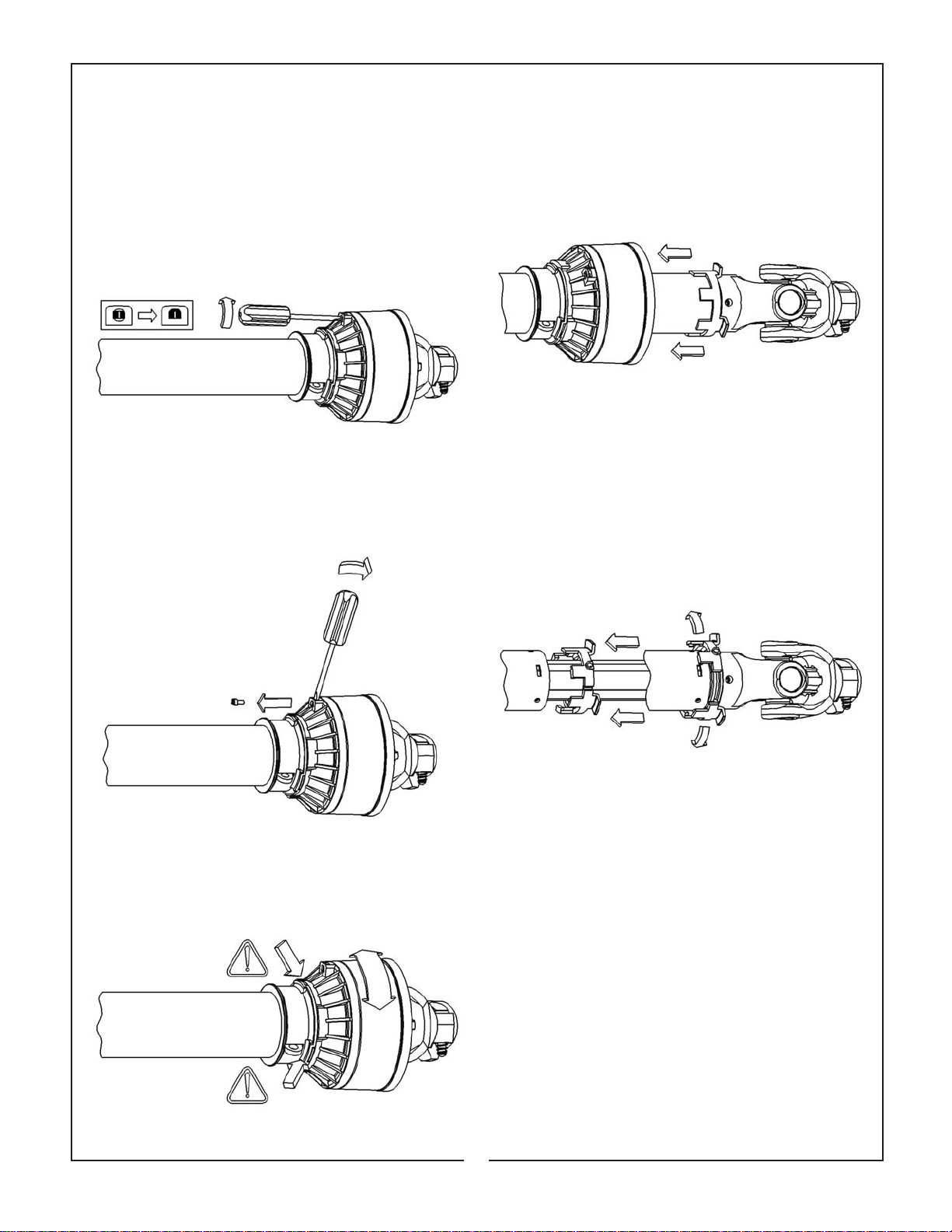
NOTE: In some instances, sliding the yoke shield back will make lubrication, inspection and cleaning
of the universal joints more convenient. Proceed as follows:
1. Using a flat blade screwdriver, rotate the fastening pin in its seat 1/2 turn until the head of the pin
becomes unlocked in its housing on the cones.
(Figure 4-2)
Figure 4-2
2. Lever up the pin through the slot, until the pin
comes out. (Figure 4-3)
Figure 4-3
4. Remove the cones from the half-joint. (Figure 4-5)
Figure 4-5
5. Remove the connecting ring from its housing on
the yoke and, at the same time, from the slots of the
guard tube, then move away the ring and the tube.
(Figure 4-6)
Figure 4-6
3. Rotate the soft cone until the slots are aligned
with the corresponding ones of the rigid cone.
(Figure 4-4)
Figure 4-4
Reassembly is in the reverse order
11
Page 14
4-3 BLADE REPLACEMENT
WARNING
THE TILLER CAN FALL FROM
HYDRAULIC SYSTEM FAILURE. TO
AVOID SERIOUS INJURY OR DEATH,
SECURELY SUPPORT TILLER BEFORE
WORKING UNDERNEATH.
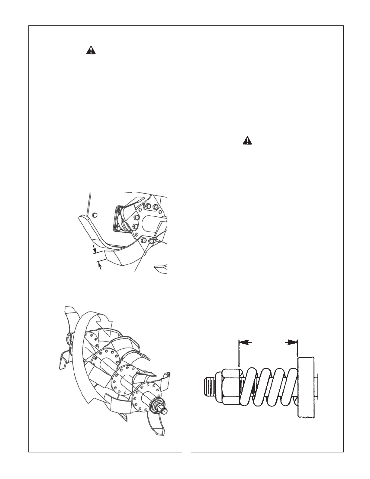
Tiller blades should be replaced when they have
approximately 1/4” of wear left on tip of blade.(Figure
4-7) To replace blades, remove bolts securing blade.
Install new blade in its place. Blade must be a right
or left corresponding to the blade removed. Pay special attention to the bolts on the blades; the bolt head
must be placed on the blade side, with the washer
and the nut on the flange side so that the bolts cannot loosen while the equipment is being used. When
several blades must be replaced, replace one blade
at a time, so that the initial layout is maintained.
(Figure 4-8) Tighten blade bolts to 70 ft. lbs. Use
only genuine Bush Hog replacement parts.
4-4 SLIP CLUTCH OPERATIONAL
CHECK
After tiller has been stored for 30 days or more,
perform the following operational check:
A. Loosen eight nuts retaining clutch springs
exactly one full turn.
B. With tiller blades firmly on ground and tractor
at idle speed, engage tractor PTO drive for 2-3 seconds. Clutch should slip without turning blades. If
clutch does not slip, contact your authorized Bush
Hog dealer.
C. Retighten nuts to within 1/64” of original position.
Initial spring length is 1-1/16” (27mm). (Figure 4-9)
CAUTION
FAILURE TO RETIGHTEN SPRING NUTS
TO ORIGINAL POSITION MAY CAUSE
DAMAGE TO TILLER AND/OR TRACTOR
DUE TO IMPROPER SLIP CLUTCH
TORQUE SETTING.
Figure 4-7
1/4” Minimum
Figure 4-8
Helical Arrangement
Bolt Head
Against Blade
4-5 SLIP CLUTCH ADJUSTMENT
The slip clutch is factory preset to the correct torque
for protecting implement and tractor. Periodic
adjustment is recommended; refer to Section 4-4.
Should adjustment be needed, first check to be sure
all spring lengths are within 1/64” of being the same.
Initial spring length is 1-1/16” (27mm) shown in
Figure 4-9. If necessary, loosen nut on any spring
that is unequal. Adjust all eight spring retaining nuts
2/3 of a turn (2 flats on a nut) and check clutch slippage. If further adjustment is necessary, do so in 1/3
turn increments or consult your Bush Hog dealer.
Adjust only to provide sufficient torque to prevent
slippage under normal conditions. When rocks, roots,
etc. are present, occasional slippage is normal for
drivetrain protection.
Figure 4-9
Clutch Spring Length
1-1/16”
(27mm)
12
Page 15
4-7 TROUBLESHOOTING
Troubleshooting procedures are listed in Table 4-1
below. If the problem cannot be solved or replace-
Table 4-1 Troubleshooting
PROBLEM PROBABLE CAUSE REMEDY
Uneven Till Tiller not level right to left Adjust skids for same depth
Noisy Loose components Check all bolts for tightness. Refer to Torque Specs
Low oil in gearbox Check for proper oil level. Refer to Lubrication Section
Knocking or Tiller is tilted towards the rear Adjust 3-point hitch top link to level tiller
Chattering
Bogging Tractor engine speed too slow Increase engine speed to 540 PTO rpm
Ground speed too fast Use lower tractor gear
Vines wrapped around rotor Remove vines
Loose Chain Chain worn beyond self-adjusting Have dealer service chain
capacity
ment parts are necessary, contact your authorized
Bush Hog dealer. Please have ready your machine
name, model number, serial number, purchase date,
and exact cause or description of problem.
Adjust tractor lower lift arms
13
Page 16

SECTION V
DEALER ASSEMBLY
WARNING
THE FOLLOWING SAFETY PRECAUTIONS SHOULD
BE THOROUGHLY UNDERSTOOD BEFORE
ATTEMPTING MACHINE ASSEMBLY
1. Wear personal protective equipment such as, but not limited to, protection for eyes, ears, feet, hands and
head when operating or repairing the equipment. Do not wear loose clothing or jewelry that may catch on
equipment moving parts.
2. Do not lift heavy parts or assemblies. Use crane, jack, tackle, fork trucks or other mechanical devices.
3. Select an area for assembly that is clean and free of any debris which ;might cause persons working on the
assembly to trip.
4. Arrange parts to be assembled neatly in the work area and have tools or other mechanical assisting
devices in easy reach.
5. Inspect all parts and assemblies thoroughly and remove any sharp edges, grease, oil, or dirt which might
cause pieces to slip when handling.
6. Preview the assembly instructions in your operator’s manual before proceeding further.
7. If the assembly instructions call for parts or assemblies to be blocked up, use only blocking material that is
in good condition and is capable of handling the weight of the assembly to be blocked. Also insure that the
blocking material is on a clean, dry surface.
8. Never put hands or any other part of body under blocked up assemblies if at all possible.
9. Always wear goggles or safety glasses when hammering, grinding or drilling metal parts.
10.If the assembly calls for welding or cutting, be sure that there are no flammable materials close at hand and
that bystanders have taken necessary precautions.
AFTER COMPLETING ANY ASSEMBLY STEP, THOROUGHLY READ THE NEXT STEP IN THE ASSEMBLY
INSTRUCTIONS BEFORE PROCEEDING WITH THAT STEP.
11.After completing assembly, thoroughly inspect the machine to be sure that all nuts, bolts,
or any other fastened assemblies have been thoroughly tightened. (Refer to Torque Specifications, page 17}
12.After completing assembly, be sure that all safety locking devices or guards are in place.
13.Before operating the machine, thoroughly read the operation section of this manual.
14.Before operating, read the maintenance section of this manual to be sure that any parts requiring lubrication
such as gearboxes are full to avoid any possible damage.
BEFORE OPERATING THE EQUIPMENT, IF YOU HAVE ANY QUESTIONS REGARDING THE PROPER
ASSEMBLY OR OPERATION, CONTACT YOUR AUTHORIZED BUSH HOG DEALER OR REPRESENTATIVE.
14
Page 17
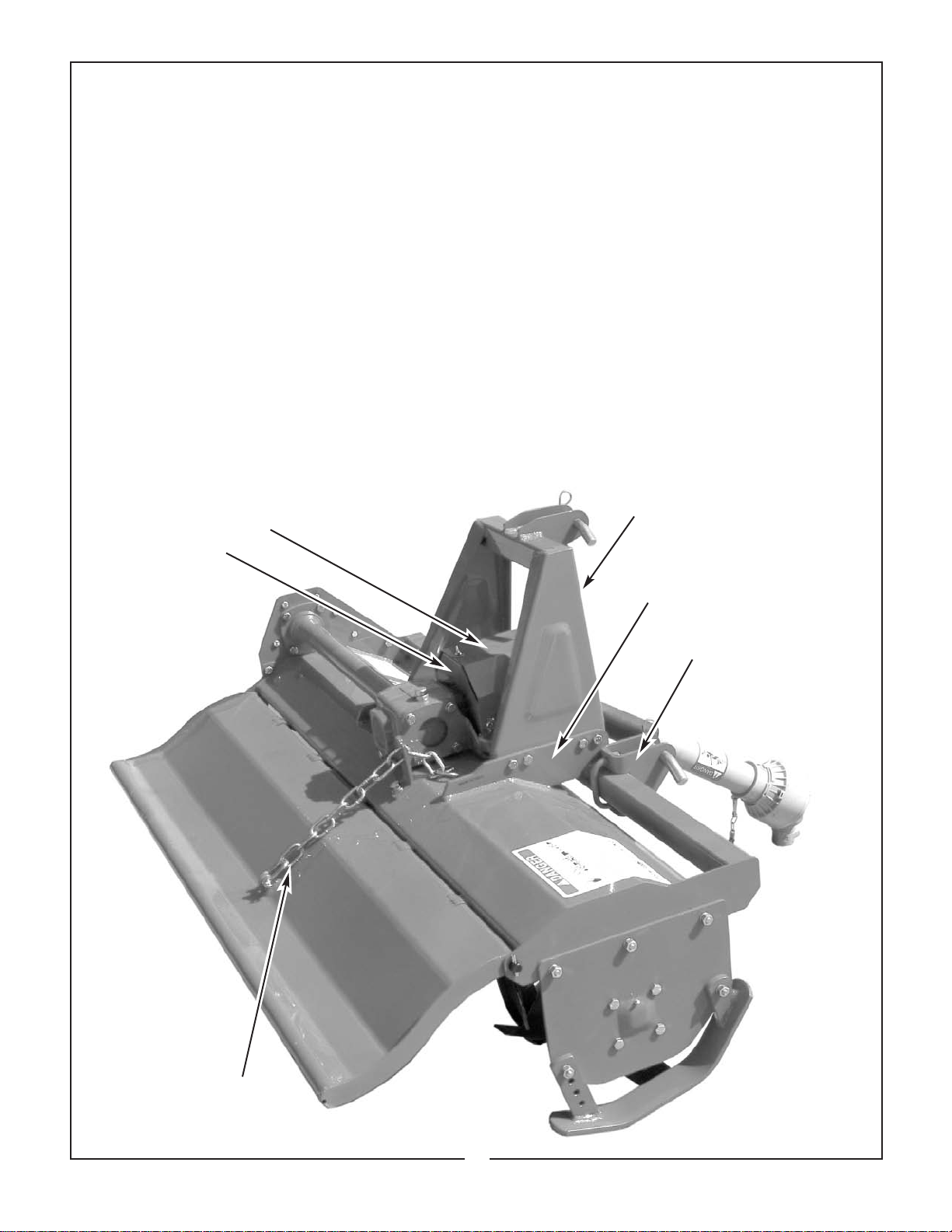
NOTICE: Refer to Figures 1-1, 3-1, 4-1 and 5-1
for visual reference to aid assembly.
A. The parking stand is shipped installed in the
upside down position. Remove the stand and replace
it in the correct position. Pin into the “parked” position.
B. Place the slip clutch shield support pate
against the front of the gearbox and fasten with(4)
M8 x 16mm bolts and lockwashers .
C. Remove the cross bolt from the end of the slip
clutch. Slide the slip clutch onto the gearbox input
shaft and align the cross bolt hole with the groove in
the input shaft. Replace the cross bolt and tighten
securely .
D. Position the slip clutch shield over the support
plate and fasten into position with (3) M8 x 16mm
bolts and lockwashers.
E. Place the “A” frame weldment into position
against the strongbacks on the main frame and fasten with (8) M10 x 35mm bolts and flanged locknuts.
F. Place lower hitch pin brackets on front cross
member of frame and fasten into position using M12
U-bolts and flanged locknuts. Notice that the hitch
pin brackets can be positioned to best match the lift
arms on your particular tractor.
G. Attach one end of rear deflector adjustment
chain to rear deflector with the clevis provided. The
other end will fit into the slot next to the gearbox.
IMPORTANT
Before delivery to customer, perform SLIP
CLUTCH OPERATIONAL CHECK as described in
Section 4-4, page 11.
NOTE
It is important that the customer receives this operator’s manual with his machine. Safe and satisfactory
performance of this machine depends on the operator knowing the correct operating and maintenance
procedures. The customer should be reminded to fill
out and mail in the warranty registration card within
ten days of purchase.
Slip clutch Shield
and Support Plate
Figure 5-1
“A” Frame
Strongback
Lower Hitch Pin Bracket
Rear Deflector
Adjustment Chain
15
Page 18
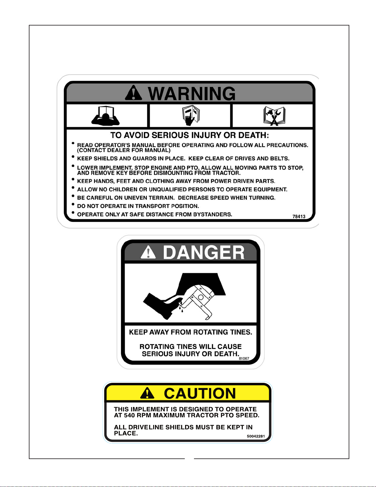
SAFETY DECALS
To promote safe operation, Bush Hog supplies safety decals on all products manufactured. Because damage
can occur to safety decals either through shipment, use or reconditioning, Bush Hog will, upon request, provide
safety decals for any of our products in the field at no charge. Contact your authorized Bush Hog dealer for
more information.
Part No. 81067
Part No. 78413
16
Part No. 50042281
Page 19
Wrench
Size “A”
AMERICAN
Bolt Head Markings
SAE Grade 2
(No Dashes)
SAE Grade 5
(3 Dashes)
SAE Grade 8
(6 Dashes)
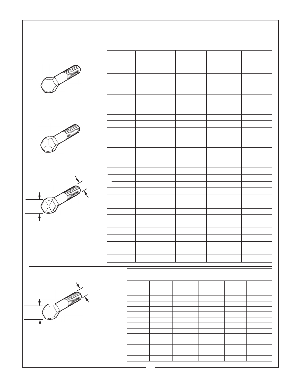
TORQUE SPECIFICATIONS
Proper toque for American fasteners used on Bush Hog equipment.
Recommended Torque in Foot Pounds (Newton Meters).*
B OL T D IA M E TE R
Bolt
Diameter “B”
W R ENC H (I N .) “B ” A ND S A E S A E S A E
S IZ E (IN. ) “A ” T H R EA D S IZ E G R A DE 2 G R AD E 5 G R AD E 8
7/16 1/4 - 2O UNC 6 (7) 8 (11) 12 (16)
7/16 1/4 - 28 UNF 6 (8) 10 (13) 14 (18)
1/2 5/16 - 18 UNC 11 (15) 17 (23) 25 (33)
1/2 5/16 - 24 UNF 13 (17) 19 (26) 27 (37)
9/16 3/8 - 16 UNC 20 (27) 31 (42) 44 (60)
9/16 3/8 - 24 UNF 23 (31) 35 (47) 49 (66)
5/8 7/16 - 14 UNC 32 (43) 49 (66) 70 (95)
5/8 7/16 - 20 UNF 36 (49) 55 (75) 78 (106)
3/4 1/2 - 13 UNC 49 (66) 76 (103) 106 (144)
3/4 1/2 - 20 UNF 55 (75) 85 (115) 120 (163)
7/8 9/16 - 12 UNC 70 (95) 109 (148) 153 (207)
7/8 9/16 - 18 UNF 79 (107) 122 (165) 172 (233)
15/16 5/8 - 11 UNC 97 (131) 150 (203) 212 (287)
15/16 5/8 - 18 UNF 110 (149) 170 (230) 240 (325)
1-1/8 3/4 - 10 UNC 144 (195) 266 (360) 376 (509)
1-1/8 3/4 - 16 UNF 192 (260) 297 (402) 420 (569)
1-5/16 7/8 - 9 UNC 166 (225) 430 (583) 606 (821)
1-5/16 7/8 - 14 UNF 184 (249) 474 (642) 668 (905)
1-1/2 1 - 8 UNC 250 (339) 644 (873) 909 (1232)
1-1/2 1 - 12 UNF 274 (371) 705 (955) 995 (1348)
1-1/2 1 - 14 UNF 280 (379) 721 (977) 1019 (1381)
1-11/16 1-1/8 - 7 UNC 354 (480) 795 (1077) 1288(1745)
1-11/16 1-1/8 - 12 UNF 397 (538) 890 (1206) 1444 (1957)
1-7/8 1-1/4 - 7 UNC 500 (678) 1120 (1518) 1817 (2462)
1-7/8 1-1/4 - 12 UNF 553 (749) 1241 (1682) 2013 (2728)
2-1/16 1-3/8 - 6 UNC 655 (887) 1470 (1992) 2382 (3228)
2-1/16 1-3/8 - 12 UNF 746 (1011) 1672 (2266) 2712 (3675)
2-1/4 1-1/2 - 6 UNC 870 (1179) 1950 (2642) 3161 (4283)
2-1/4 1-1/2 - 12 UNF 979 (1327) 2194 (2973) 3557 (4820)
METRIC
Bolt
Diameter “B”
Wrench
Size “A”
*Use 7 5 % of th e s p e ci fied to rqu e va lue fo r
p la te d fast ener s. U se 8 5 % o f the s p eci -
fied to rq ue val ues fo r lu b ri cat ed fa s te n e rs .
8.8
Numbers appearing on bolt heads
indicate ASTM class.
Proper torque for metric fasteners used on Bush Hog equipment.
Recommended torque in foot pounds (newton Meters).*
—WRENCH BOLT
SIZE DIA. ASTM ASTM ASTM ASTM
(mm) “A” (mm) “B” 4.6 8.8 9.8 10.9
851.8 (2.4) 5.1 (6.9) 6.5 (8.8)
10 6 3 (4) 8.7 (12) 11.1 (15)
13 8 7.3 (10) 21.1 (29) 27 (37)
16 10 14.5 (20) 42 (57) 53 (72)
18 12 25 (34) 74 (100) 73 (99) 93 (126)
21 14 40 (54) 118 (160) 116 (157) 148 (201)
24 16 62 (84) 167 (226) 181 (245) 230 (312)
30 20 122 (165) 325 (440) 449 (608)
33 22 443 (600) 611 (828)
36 24 211 (286) 563 (763) 778 (1054)
41 27 821 (1112) 1138 (1542)
46 30 418 (566) 1119 (1516) 1547 (2096)
17
Page 20

P.O. Box 1039 llSelma, AL 36702-1039
Telephone (334) 874-2700
ll
www.bushhog.com
 Loading...