

Page 1
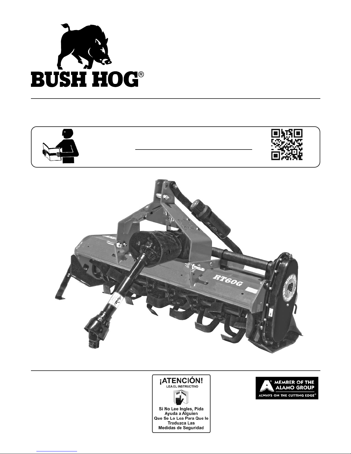
RTG SERIES TILLERS
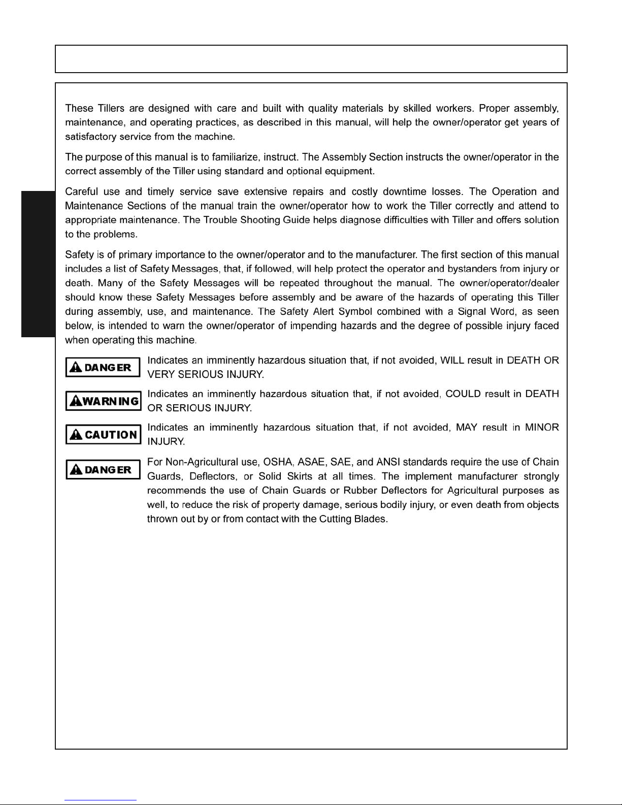
(ROTO HOG)
MODELS
RT60G, RT72G, RT84G
RT60GR, RT72GR, RT84GR
Published 05/16 Revised 08/18
Part No. 50075234
OPERATOR’S MANUAL
www.bushing.com
This Operator's Manual is an integral part of the safe operation of this machine and must be maintained with the
unit at all times. READ, UNDERSTAND, and FOLLOW the
Safety and Operation Instructions contained in this manual before operating the equipment.
BUSH HOG
®
2501 Griffin Avenue
Selma, Al. 36703
334-874-2700
www.bushing.com
Page 2

To the Owner/Operator/Dealer
All implements with moving parts are potentially hazardous. There is no substitute for a cautious,
safe-minded operator who recognizes the potential hazards and follows reasonable safety parctices. The manufacturer has designed this implement to be used with all its safety equipment
properly attached to minimize the chance of accidents.
BEFORE YOU START! Read the safety messages on the implement and shown in your manual.
Observe the rules of safety and common sense!
Dealer Telephone Model Number
Owner Purchase Date Serial Number
SERIAL NUMBER LOCATION
WARRANTY INFORMATION:
Read and understand the complete Warranty Statement found in this manual. Be sure
your dealer has filed your Warranty on line with Bush Hog at time of purchase.
Page 3

TABLE OF CONTENTS
SAFETY SECTION ................................................................................................................1-1
General Safety Instructions and Practices..........................................................................1-2
Operator Safety Instructions and Practices ........................................................................1-4
Equipment Operation Safety and Practices ........................................................................1-5
Transporting Safety Instructions and Practices...................................................................1-6
Maintenance and Servive Safety Instructions and Practices ..............................................1-7
Storage and Parking Safety Instructions and Practices....................................................1-10
Parts Information ...............................................................................................................1-11
Safety Decals....................................................................................................................1-12
Federal Laws and Regulations .........................................................................................1-17
INTRODUCTION SECTION...................................................................................................2-1
Limited Warranty.................................................................................................................2-5
ASSEMBLY SECTION...........................................................................................................3-1
Machine uncrating and preparation ....................................................................................3-2
Assembly ............................................................................................................................3-3
Driveline Attachment...........................................................................................................3-5
Lubrication ..........................................................................................................................3-6
Conversion from Standard Rotation to Reverse Rotation...................................................3-8
OPERATION SECTION .........................................................................................................4-1
Standard Equipment and Specifications .............................................................................4-3
Operator Requirements ......................................................................................................4-4
Tractor Requirements .........................................................................................................4-5
ROPS and Seat Belts .........................................................................................................4-5
Tractor Safety Devices........................................................................................................4-5
Tractor 3 Point Hitch ..........................................................................................................4-6
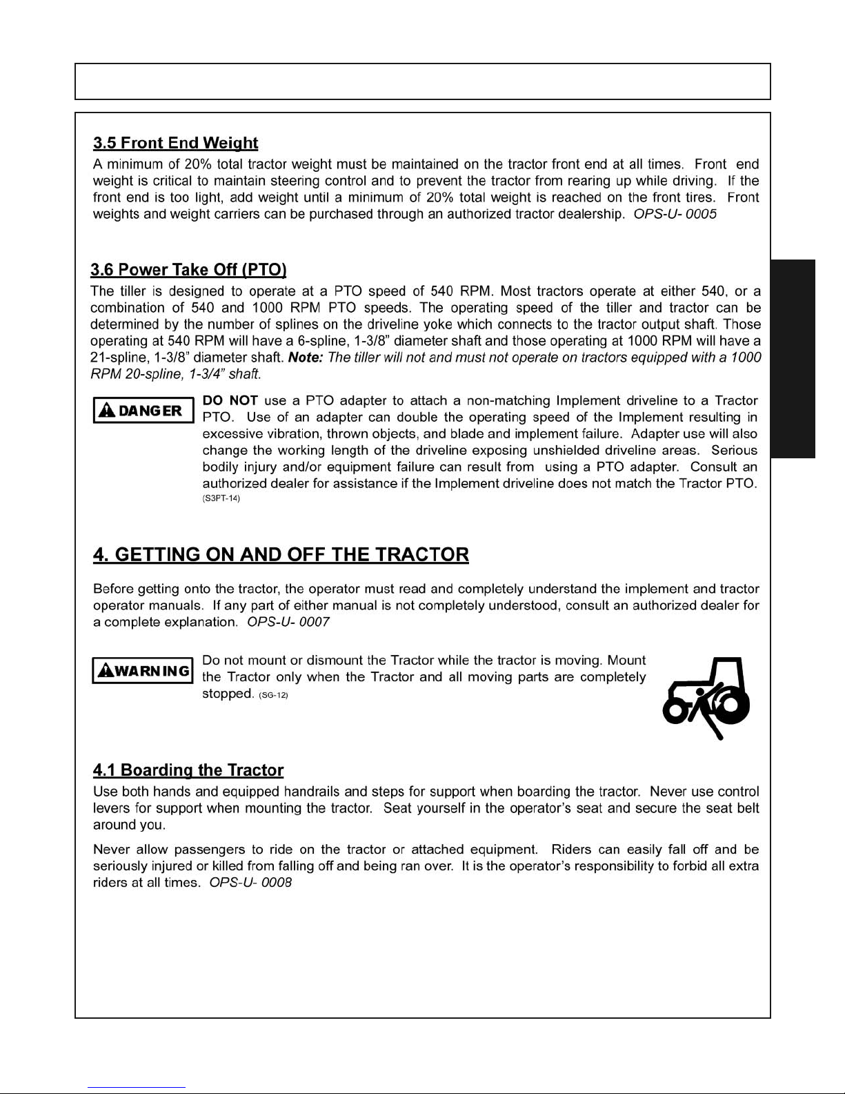
Front End Weight ................................................................................................................4-7
Power Take Off (PTO).........................................................................................................4-7
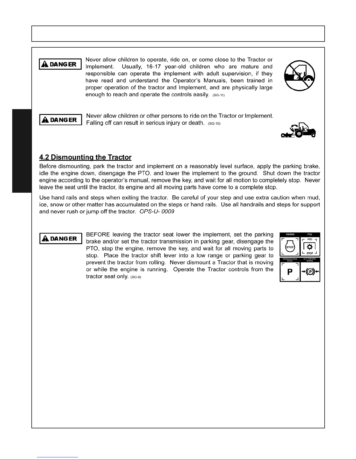
Getting on and off the tractor ..............................................................................................4-7
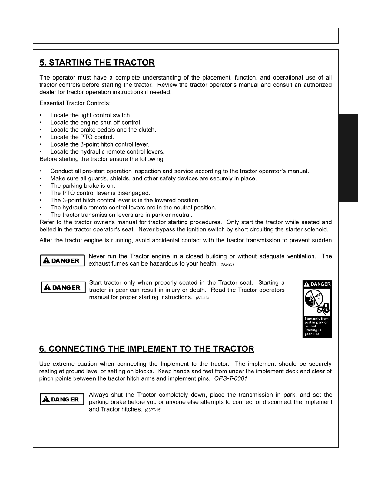
Starting the Tractor .............................................................................................................4-9
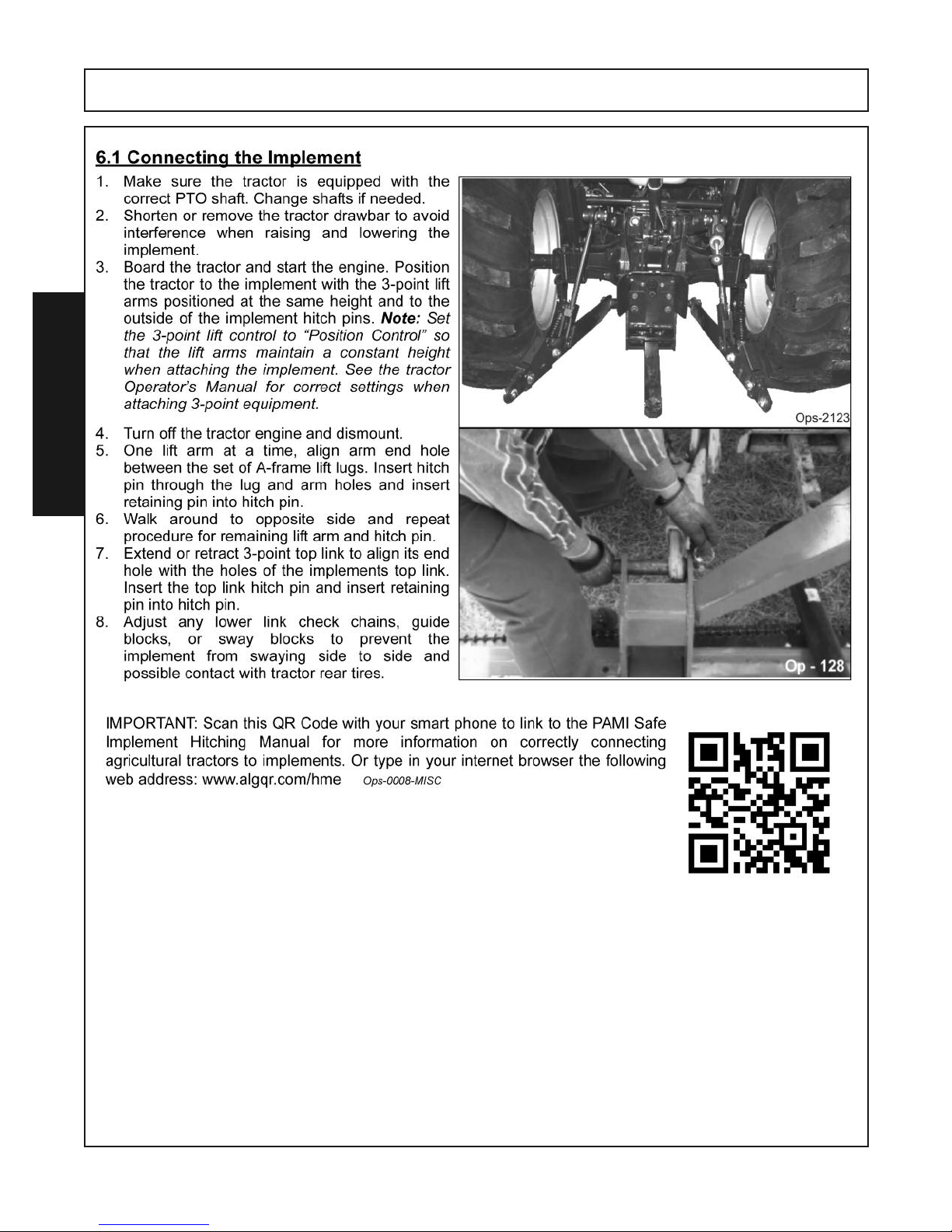
Connecting the Implement to the Tractor............................................................................4-9
Driveline Attachment .........................................................................................................4-11
Driveline Length Check.....................................................................................................4-12
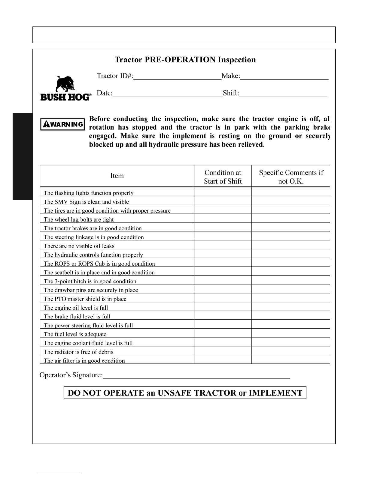
Tractor Pre-Operation Inspection and Service..................................................................4-16
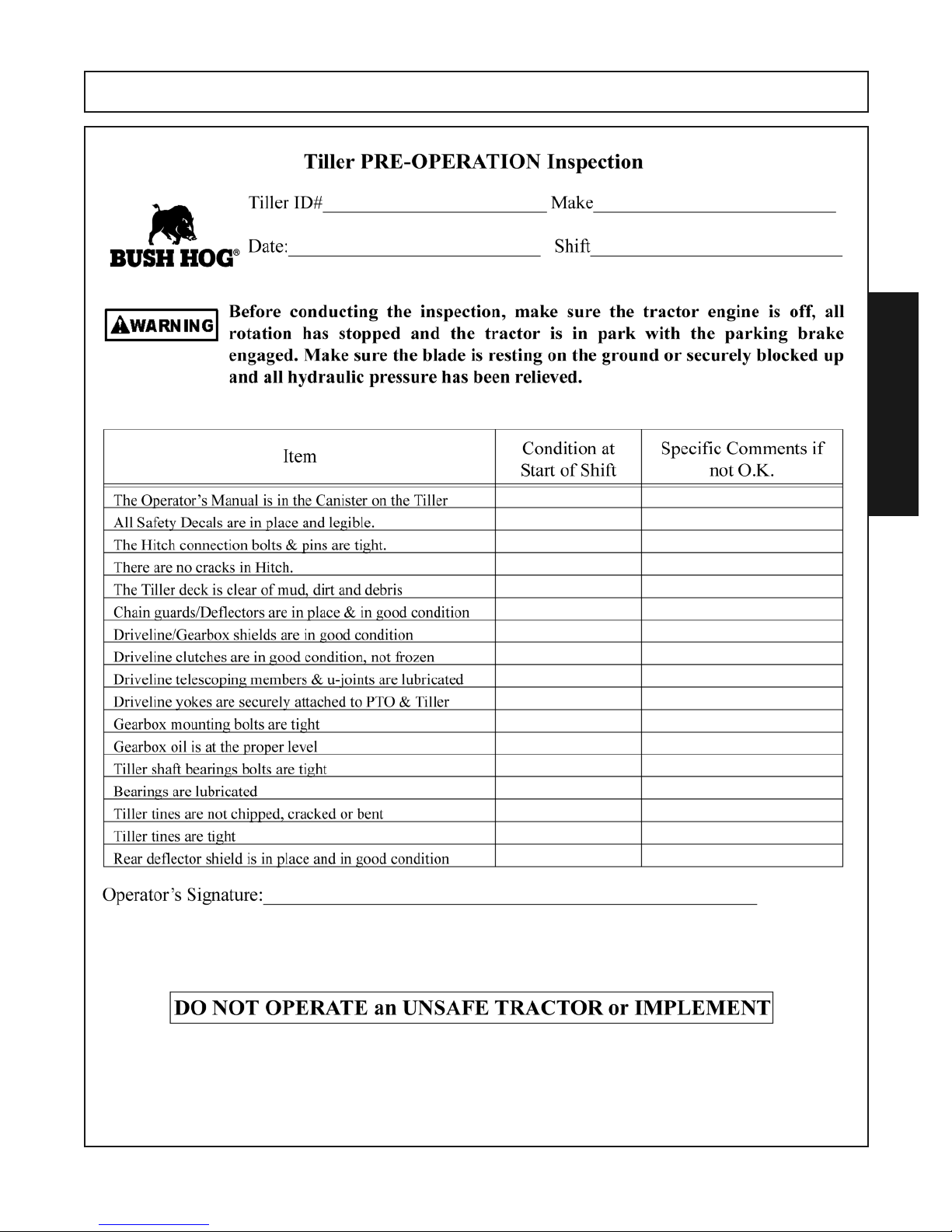
Implement Pre-Operation and Service..............................................................................4-16
Operating the Tractor and Implement ...............................................................................4-18
Adjusting Tiller For Work ...................................................................................................4-19
Operating the Tiller............................................................................................................4-19
Disconnecting the Implement from the Tractor .................................................................4-22
Transporting the Tractor and Implement ...........................................................................4-23
Driving the Tractor and Implement....................................................................................4-23
Hauling the Tractor and Implement...................................................................................4-27
Trouble Shooting Guide ....................................................................................................4-28
Page 4

MAINTENANCE SECTION....................................................................................................5-1
Lubrication........................................................................................................................................5-2
Outboard Bearing.............................................................................................................................5-2
Top Gearbox.....................................................................................................................................5-3
Side Gearbox ...................................................................................................................................5-3
Driveshaft Lubrication.......................................................................................................................5-4
Slipclutch Maintenance ....................................................................................................................5-5
General Maintenance.......................................................................................................................5-6
Fastener Torque Chart .....................................................................................................................5-7
Page 5

SAFETY SECTION
Safety Section 1-1
Page 6
SAFETY
General Safety Instructions and Practices
A careful operator is the best operator. Safety is of primary importance to the manufacturer and should be to the
owner/operator. Most accidents can be avoided by being aware of your equipment, your surroundings, and observing certain precautions. The first section of this manual includes a list of Safety Messages that, if followed,
will help protect the operator and bystanders from injury or death. Read and understand these Safety Messages
before assembling, operating or servicing this Implement. This equipment should only be operated by those per-
sons who have read the manual, who are responsible and trained, and who know how to do so responsibly.
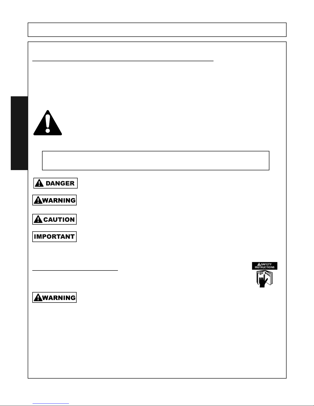
The Safety Alert Symbol combined with a Signal Word, as seen below, is used throughout this
manual and on decals which are attached to the equipment.The Safety Alert Symbol means:
“ATTENTION! BECOME ALERT! YOUR SAFETY IS INVOLVED!” The Symbol and Signal Word
are intended to warn the owner/operator of impending hazards and the degree of possible injury
faced when operating this equipment.
SAFETY
Practice all usual and customary safe working precautions and above all---remember safety is up
to YOU. Only YOU can prevent serious injury or death from unsafe practices.
Indicates an imminently hazardous situation that, if not avoided, WILL result in DEATH OR
VERY SERIOUS INJURY.
Indicates an imminently hazardous situation that, if not avoided, COULD result in DEATH
OR SERIOUS INJURY.
Indicates an imminently hazardous situation that, if not avoided, MAY result in MINOR INJURY.
Identifies special instructions or procedures that, if not strictly observed, could result in
damage to, or destruction of the machine, attachments or the environment.
NOTE:
READ, UNDERSTAND, and FOLLOW the following Safety Messages. Serious injury or death
may occur unless care is taken to follow the warnings and instructions stated in the Safety
Messages. Always use good common sense to avoid hazards. (SG-2)
Identifies points of particular interest for more efficient and convenient operation or repair.(SG-1)
Always maintain the safety signs in good readable condition. If the safety signs are missing, damaged, or unreadable, obtain and install replacement safety signs immediately.
RTG SERIES TILLER 05/16 Safety Section 1-2
© 2015 Alamo Group.Inc
.
Page 7
SAFETY
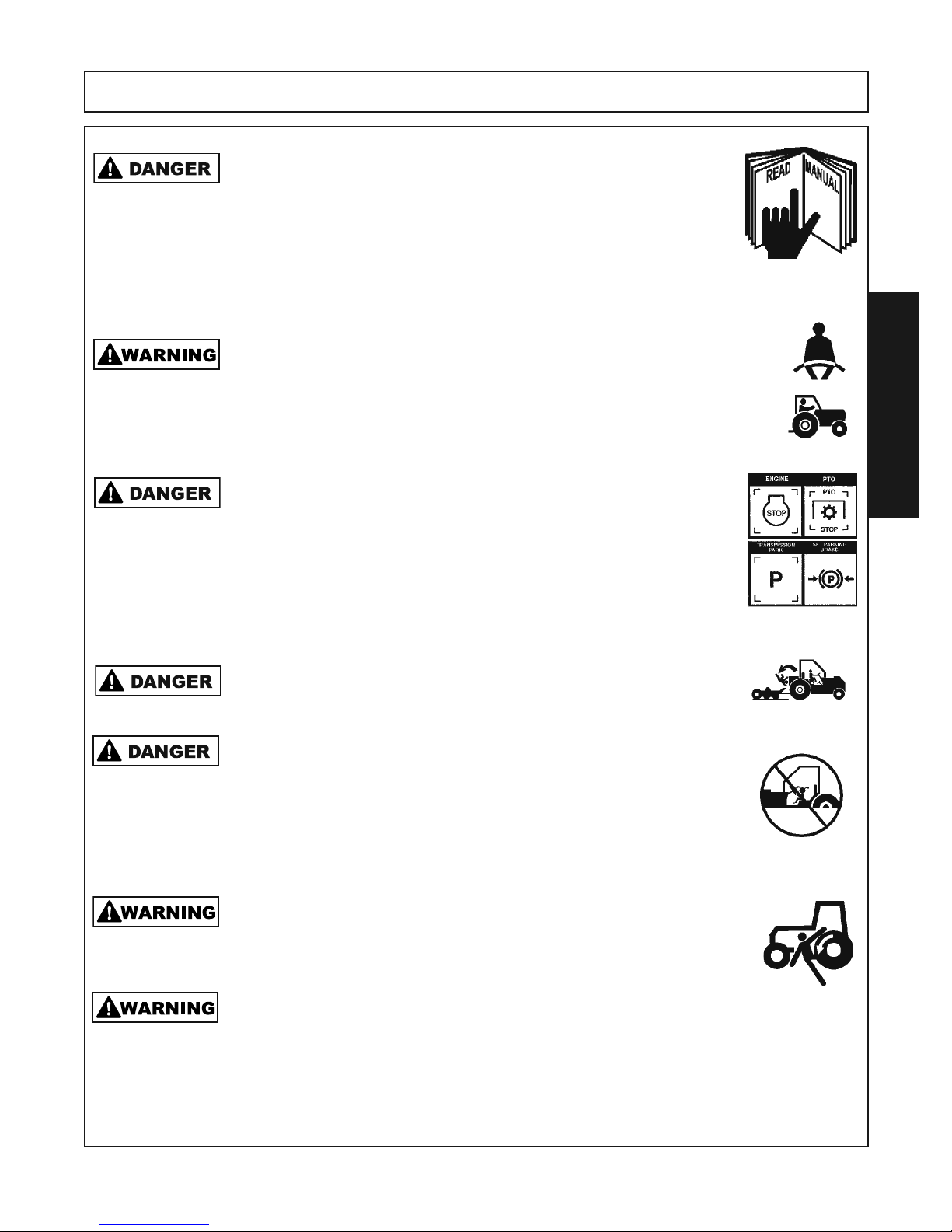
Never operate the Tractor or Implement until you have read and
completely understand this Manual, the Tractor Operator’s Manual, and
each of the Safety Messages found in the Manual or on the Tractor and
Implement. Learn how to stop the tractor engine suddenly in an
emergency. Never allow inexperienced or untrained personnel to
operate the Tractor or Implement without supervision. Make sure the
operator has fully read and understood the manuals prior to operation.
Operate this Equipment only with a Tractor equipped with an approved
roll-over-protective system (ROPS). Always wear seat belts. Serious injury
or even death could result from falling off the tractor--particularly during a
turnover when the operator could be pinned under the ROPS. (SG 7)
BEFORE leaving the tractor seat, always engage the parking brake and/
or set the tractor transmission in parking gear, disengage the PTO, stop
the engine, remove the key, and wait for all moving parts to stop. Place
the tractor shift lever into a low range or parking gear to prevent the
tractor from rolling. Never dismount a Tractor that is moving or while the
engine is running. Operate the Tractor controls from the tractor seat only.
(SG 9)
Never allow children or other persons to ride on the Tractor or Implement.
Falling off can result in serious injury or death. (SG 10)
Never allow children to operate, ride on, or come close to the Tractor or
Implement. Usually, 16-17 year-old children who are mature and
responsible can operate the implement with adult supervision, if they
have read and understand the Operator’s Manuals, been trained in
proper operation of the tractor and Implement, and are physically large
enough to reach and operate the controls easily. (SG 11)
SAFETY
Do not mount or dismount the Tractor while the tractor is moving. Mount
the Tractor only when the Tractor and all moving parts are completely
stopped.(SG 12)
Do not modify or alter this Implement. Do not permit anyone to modify or
alter this Implement, any of its components or any Implement function.
(SG 8)
RTG SERIES TILLER 05/16 Safety Section 1-3
© 2015 Alamo Group.Inc.
Page 8
SAFETY
Operator Safety Instructions and Practices
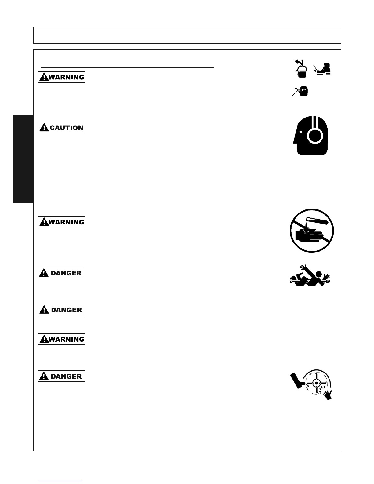
The operator and all support personnel should wear hard hats, safety
shoes, safety glasses, and proper hearing protection at all times for
protection from injury including injury from items that may be thrown by
the equipment. (SG-16)
PROLONGED EXPOSURE TO LOUD NOISE MAY CAUSE
PERMANENT HEARING LOSS! Tractors with or without an Implement
attached can often be noisy enough to cause permanent hearing loss.
We recommend that you always wear hearing protection if the noise in
the Operator’s position exceeds 80db. Noise over 85db over an
extended period of time will cause severe hearing loss. Noise over 90db
adjacent to the Operator over an extended period of time will cause
SAFETY
permanent or total hearing loss. NOTE: Hearing loss from loud noise
[from tractors, chain saws, radios, and other such sources close to the
ear] is cumulative over a lifetime without hope of natural recovery. (SG-I7)
Always read carefully and comply fully with the manufacturer’s
instructions when handling oil, solvents, cleansers, and any other
chemical agent. (SG-22)
KEEP AWAY FROM ROTATING ELEMENTS to prevent entanglement
and possible serious injury or death. (SG-24)
Never allow children to play on or around Tractor or Implement. Children
can slip or fall off the Equipment and be injured or killed. Children can cause
the Implement to shift or fall crushing themselves or others. (SG-25)
Be sure you have adequate knowledge of the property you will be working
on. Take time to make yourself aware of any area underground lines or cables. Contact with buried lines or cable could result in serious injury or
death. (STL-1)
Do not put hands or feet under Tiller deck. Blade Contact can result in
serious injury or even death. Stay away until all motion has stopped
and the decks are securely blocked up. (STL-3)
RTG SERIES TILLER 05/16 Safety Section 1-4
© 2015 Alamo Group.Inc.
Page 9
SAFETY
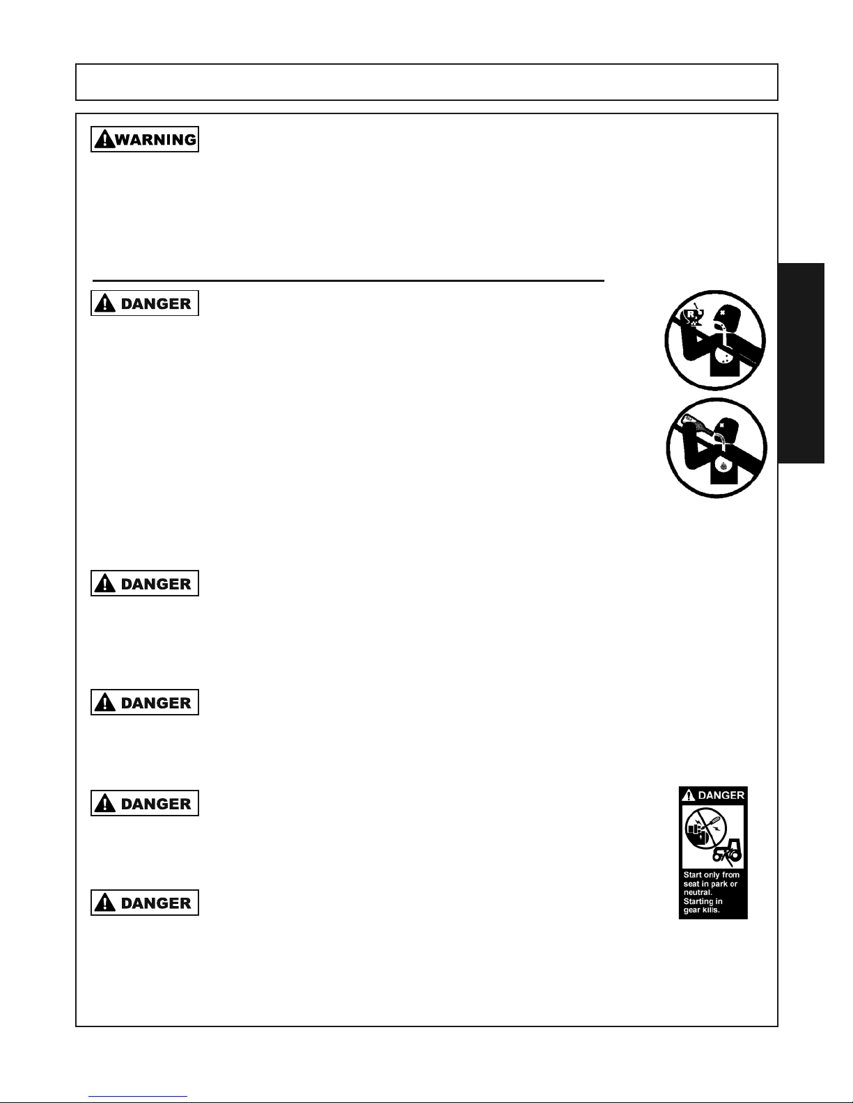
Extreme care should be taken when operating near loose objects such as
gravel, rocks, wire, and other debris. Inspect the area before tilling. Foreign
objects should be removed from the site to prevent machine damage and/or bodily injury or
even death. Any objects that cannot be removed must be clearly marked and carefully avoided
by the operator. Stop operating immediately if blades strike a foreign object. Repair all damage
and make certain rotor and blades are in good condition before resuming operation. (STL-5)
Equipment Operation Safety Instructions and Practices
NEVER use drugs or alcohol immediately before or while operating the Tractor and Implement. Drugs and alcohol will affect an operator’s alertness and coordination and therefore
affect the operator’s ability to operate the equipment safely.
Before operating the Tractor or Implement, an operator on prescription or over-the-counter medication must consult a medical professional regarding any side effects of the medication
that would hinder their ability to operate the Equipment safely.
NEVER knowingly allow anyone to operate this equipment
when their alertness or coordination is impaired. Serious injury
or death to the operator or others could result if the operator
is under the influence of drugs or alcohol. (SG-27)
SAFETY
Operate the Tractor and/or Implement controls only while properly seated in
the Tractor seat with the seat belt securely fastened around you. Inadvertent
movement of the Tractor or Implement may cause serious injury or death.
(SG-29)
Do not operate the implement while wearing loose fitting clothing. Entanglement of the clothing with the rotating elements can result in serious injury or
even death. Stay clear of all rotating elements at all times. (SSP-03)
Start tractor only when properly seated in the Tractor seat.
Starting a tractor in gear can result in injury or death. Read
the Tractor operators manual for proper starting instructions.
(SG-13)
Never run the Tractor engine in a closed building or without
adequate ventilation. The exhaust fumes can be hazardous to
your health. (SG-23)
RTG SERIES TILLER 05/16 Safety Section 1-5
© 2015 Alamo Group.Inc.
Page 10
SAFETY
SAFETY
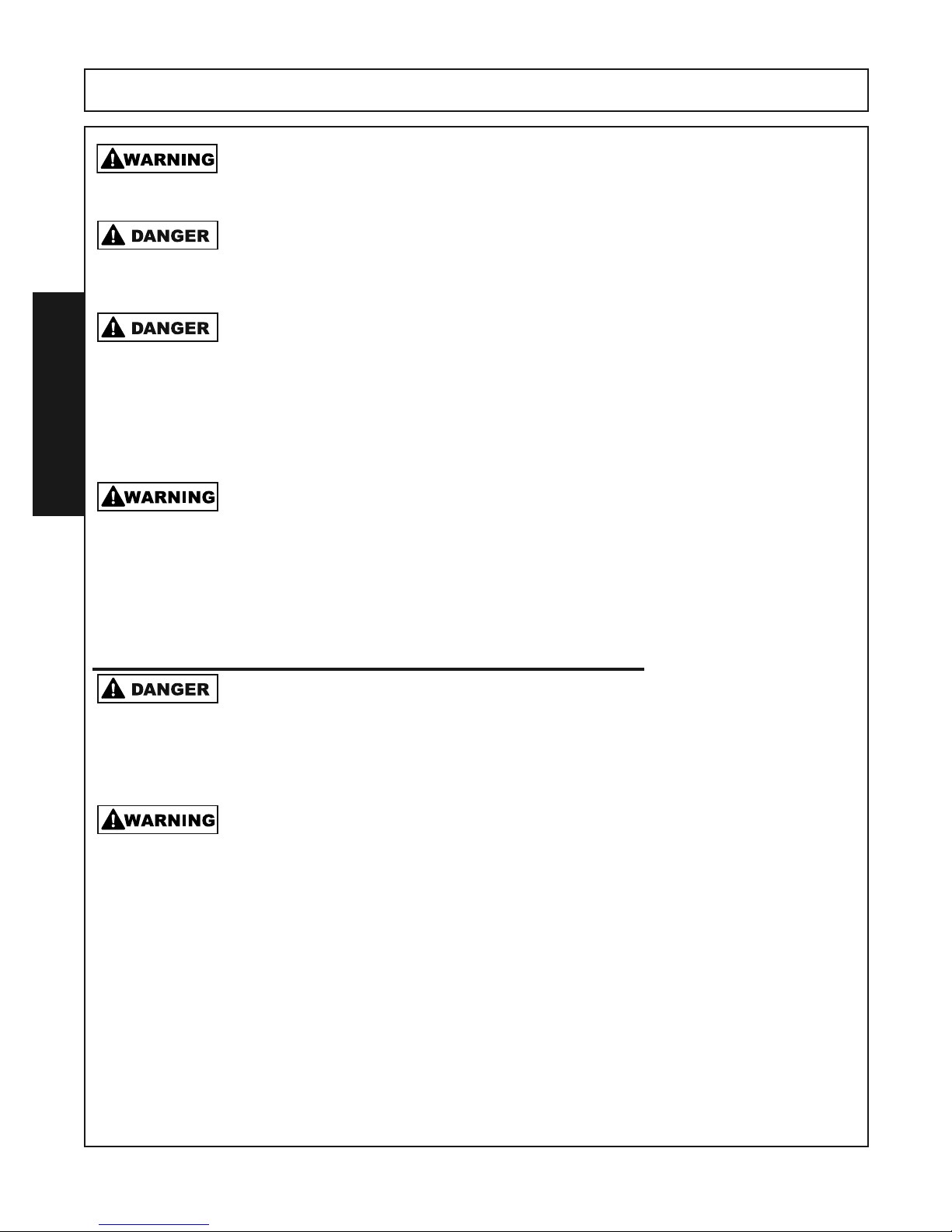
Do not exceed the rated PTO speed for the Implement. Excessive PTO speeds can cause
Implement driveline or blade failures resulting in serious injury or death. (SG-26)
Operate the Tractor and/or Implement controls only while properly seated in the Tractor seat
with the seat belt securely fastened around you. Inadvertent movement of the Tractor or
Implement may cause serious injury or death. (SG-29)
There are obvious and hidden potential hazards in the operation of this Implement as in all
power-driven or pulled equipment. REMEMBER! This machine is often operated in rough
terrain conditions that include grass, weeds, gullies, holes, slopes, hidden obstructions and
the like. Serious injury or even death may occur unless care is taken to assure the safety
of the operator and bystanders in the area. Do not operate this machine with anyone in
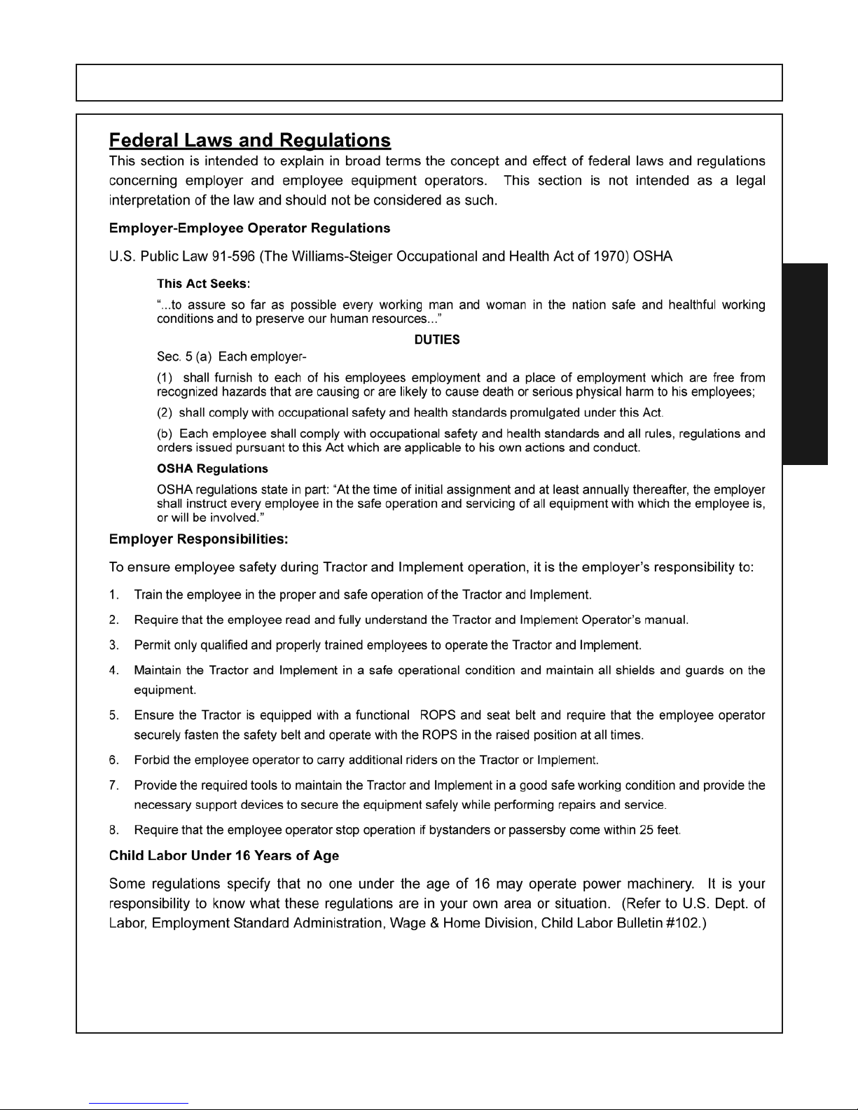
the immediate area. Stop operating if anyone comes within 25 feet of the equipment.
(STL-4)
Many varied objects, such as wire, cable, rope, or chains, can become entangled in the
rotating parts of the Implement. These objects could then swing outside the housing at
greater velocities than the blades. Such a situation is extremely hazardous and could
result in serious injury or even death. Inspect the area for such objects before working in
the area. Remove any such objects from the site. Never allow the implement to contact
such objects. (STL-6)
Transporting Safety Instructions and Practices
This Implement may be wider than the Tractor. Be careful when operating or transporting
this equipment to prevent the Implement from running into or striking sign posts, guard rails,
concrete abutments or other solid objects. Such an impact could cause the Implement and
Tractor to pivot violently resulting in loss of steering control, serious injury, or even death.
Never allow the Implement to contact obstacles. (S3PT-12)
Be particularly careful when transporting the Implement with the Tractor. Turn curves or go
up hills only at a low speed and using a gradual steering angle. Rear mounted implements
move the center of gravity to the rear and remove weight from the front wheels. Make
certain, by adding front ballast, that at least 20% of the tractor’s weight is on the front wheels
to prevent rearing up, loss of steering control or Tractor tip-over. Slow down on rough or
uneven surfaces to prevent loss of steering control which could result in property damage
or possible injury. Do not transport unless 3-Point lift lever is fully raised and in the latched
transport position. Dropping implement in transport can cause serious damage to the
tractor and/or Implement and possibly cause the operator or others to be injured or killed.
(S3PT-02)
RTG SERIES TILLER 05/16 Safety Section 1-6
© 2015 Alamo Group.Inc.
Page 11

SAFETY
SAFETY
RTG SERIES TILLER 05/16 Safety Section 1-7
© 2015 Alamo Group.Inc.
Page 12
SAFETY
SAFETY
RTG SERIES TILLER 05/16 Safety Section 1-8
© 2015 Alamo Group.Inc.
Page 13
SAFETY
SAFETY
RTG SERIES TILLER 05/16 Safety Section 1-9
© 2015 Alamo Group.Inc.
Page 14
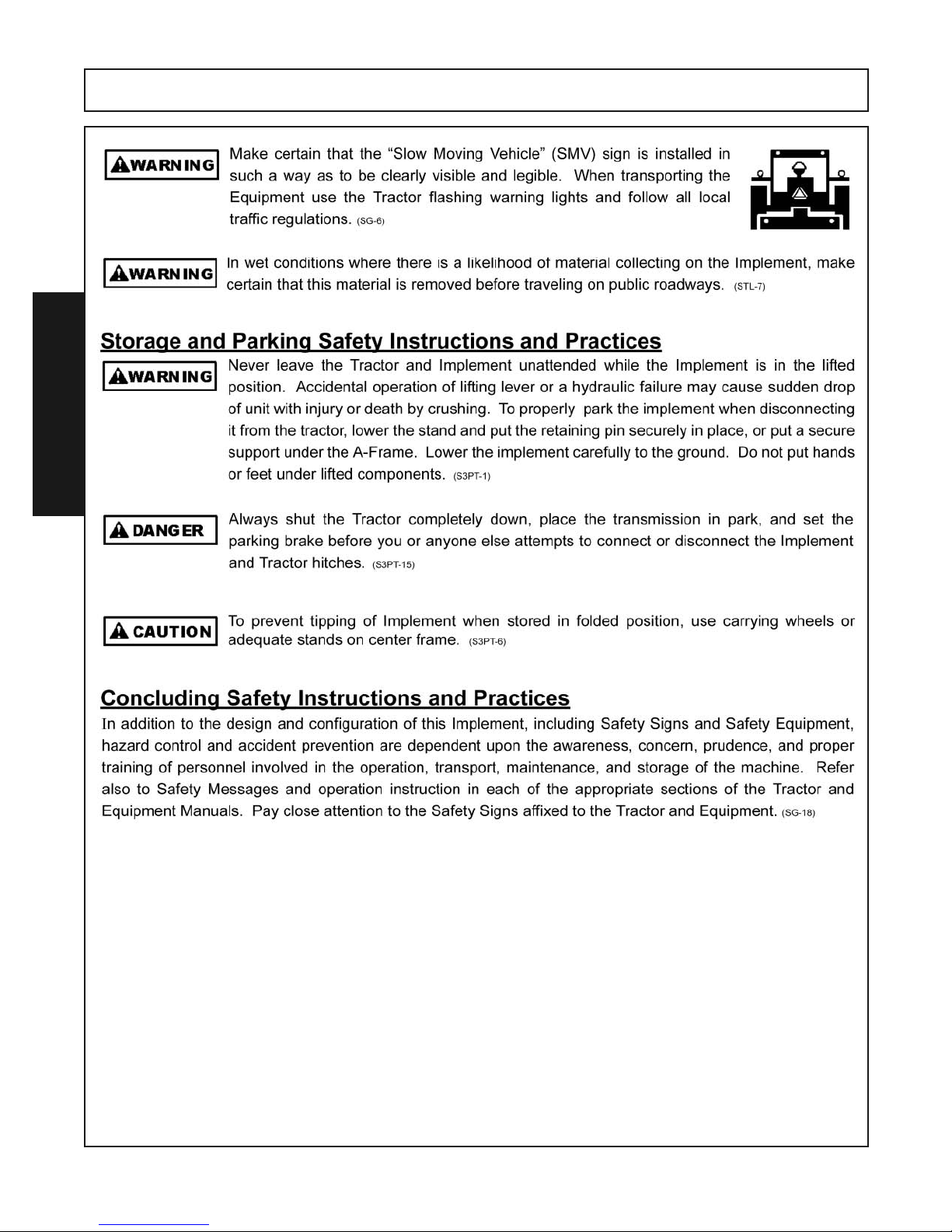
SAFETY
SAFETY
RTG SERIES TILLER 05/16 Safety Section 1-10
© 2015 Alamo Group.Inc.
Page 15
SAFETY
SAFETY
RTG SERIES TILLER 05/16 Safety Section 1-11
© Alamo Group.Inc.
Page 16
SAFETY
q
w
e
r
t
y
u
i
o
1)
1!
1!
1@
1#
1$
1%
1^
1&
SAFETY
SMV Placard
Obtain at a
Tractor Dealership
1*
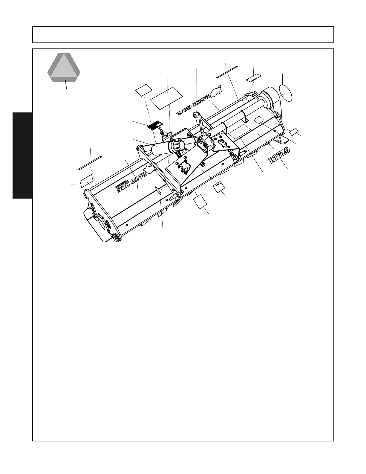
ITEM PART NO. QTY. TYPE DESCRIPTION
1 N/A 1 Serial No. Serial No. Decal
2 50075239 1 Model Decal Decal, Model Number RT60G
50075523 1 Model Decal Decal, Model Number RT60GR
50075240 1 Model Decal Decal, Model Number RT72G
50075524 1 Model Decal Decal, Model Number RT72GR
50075241 1 Model Decal Decal, Model Number RT84G
50075525 1 Model Decal Decal, Model Number RT84GR
3 50061049 1 Logo Decal Decal, Bush Hog Logo
4 50075245 1 Series Decal Decal, Roto Hog Series
5 50075246 1 Gear Drive Decal Decal, Gear Drive Logo
6 50074259 1 Flag Decal Decal, Made in USA
7 50035829 1 Manual Tube Storage Tube, Operators Manual
50075234 1 Manual Operator Manual
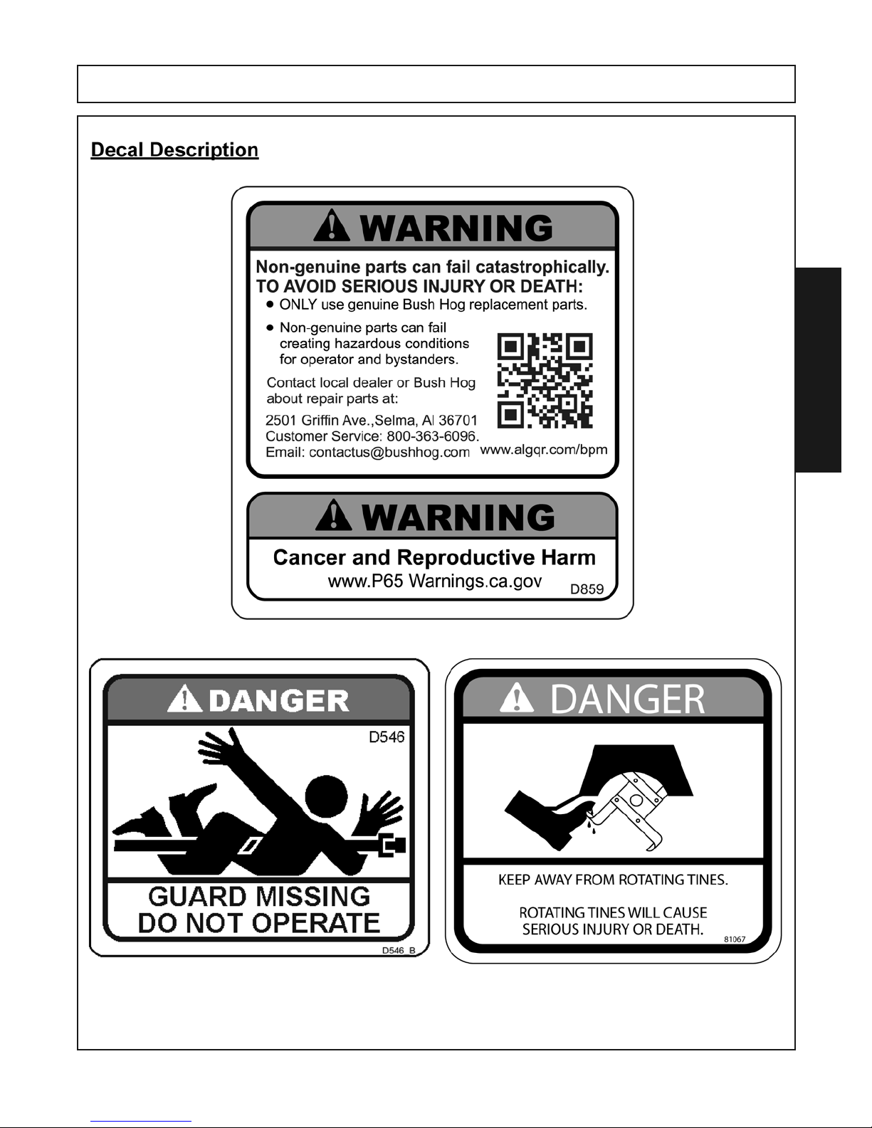
8 D859 1 Warning Decal Decal, Use Genuine Bush Hog Parts
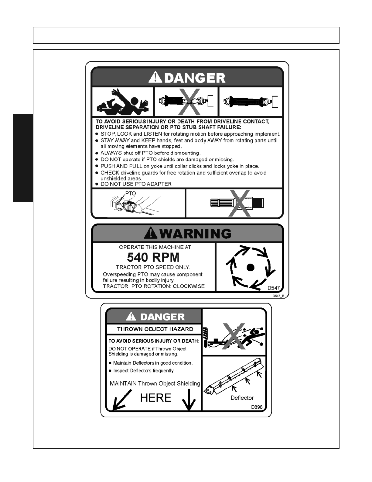
9 D546 1 Danger Decal Decal, Guard Missing Decal
10 D547 1 Caution Decal Decal, Operate at 540 RPM
11 50031214 2 Reflector Decal, Red Reflector
12 53315 1 Reflector Decal, Amber Reflector
13 81067 1 Danger Decal Decal, Keep Away Rotating Tines
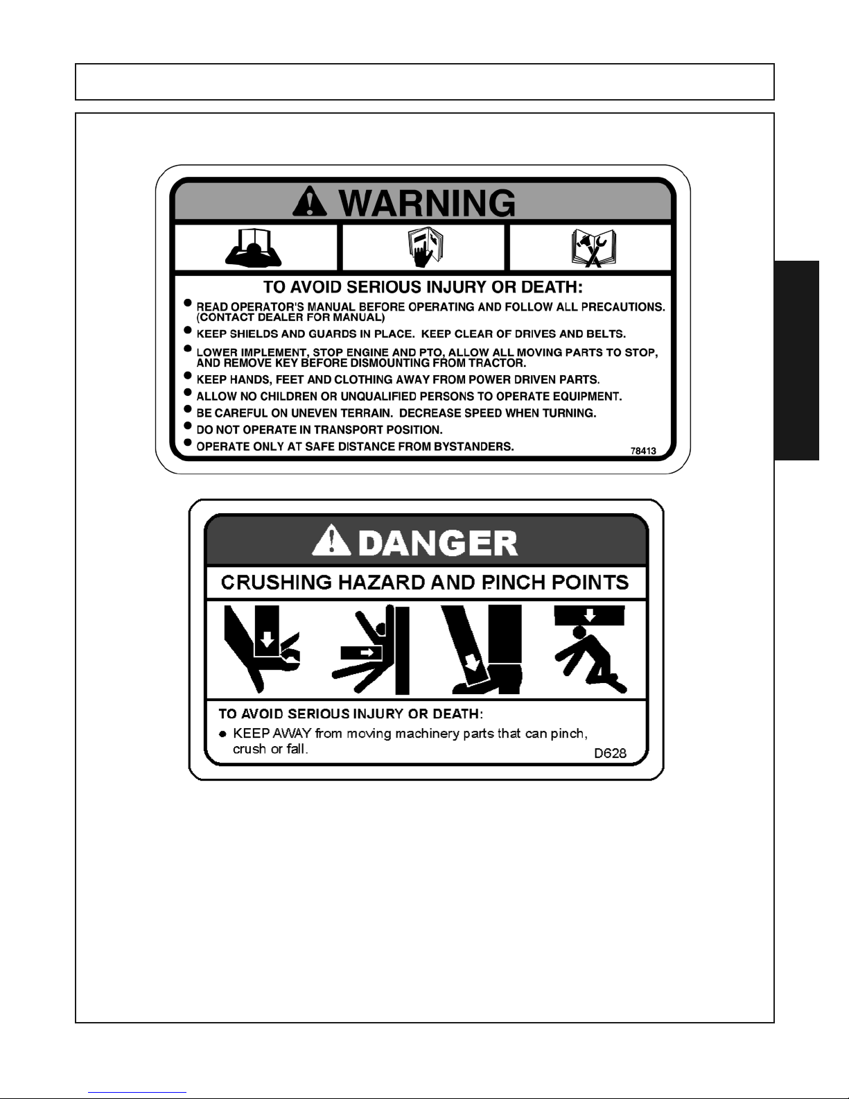
14 78413 1 Warning Decal Decal, Read Manual
15 D628 1 Danger Decal Decal, Crush Hazard / Pinch Points
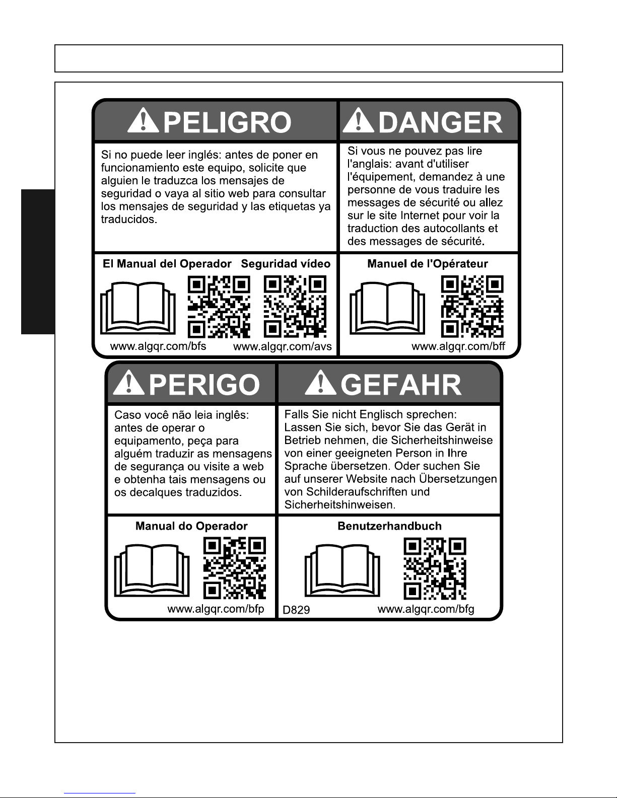
16 D829 1 Danger Decal Decal, Multilingual
17 D898 1 Danger Decal
18 -------- 1 Reflector SMV Plackard
RTG SERIES TILLER 05/16 Safety Section 1-12
Decal, Thrown Objects RT60GR, RT72GR & RT84GR
Only
© Alamo Group.Inc.
Page 17
RTG SERIES TILLER 05/16 Safety Section 1-13
© 2015 Alamo Group.Inc.
SAFETY
SAFETY
Page 18
SAFETY
SAFETY
RTG SERIES TILLER 05/16 Safety Section 1-14
© 2015 Alamo Group.Inc.
Page 19
SAFETY
SAFETY
RTG SERIES TILLER 05/16 Safety Section 1-15
© Alamo Group.Inc.
Page 20
© Alamo Group.Inc.
RTG SERIES TILLER 05/16 Safety Section 1-16
SAFETY
SAFETY
Page 21
SAFETY
SAFETY
RTG SERIES TILLER 05/16 Safety Section 1-17
© Alamo Group.Inc.
Page 22

Page 23

I
NTRODUCTION SECTION
Introduction Section 2-1
Page 24
INTRODUCTION
INTRODUCTION
RTG SERIES TILLER 05/16 Introduction Section 2-2
© 2015 Alamo Group.Inc.
Page 25
INTRODUCTION
INTRODUCTION
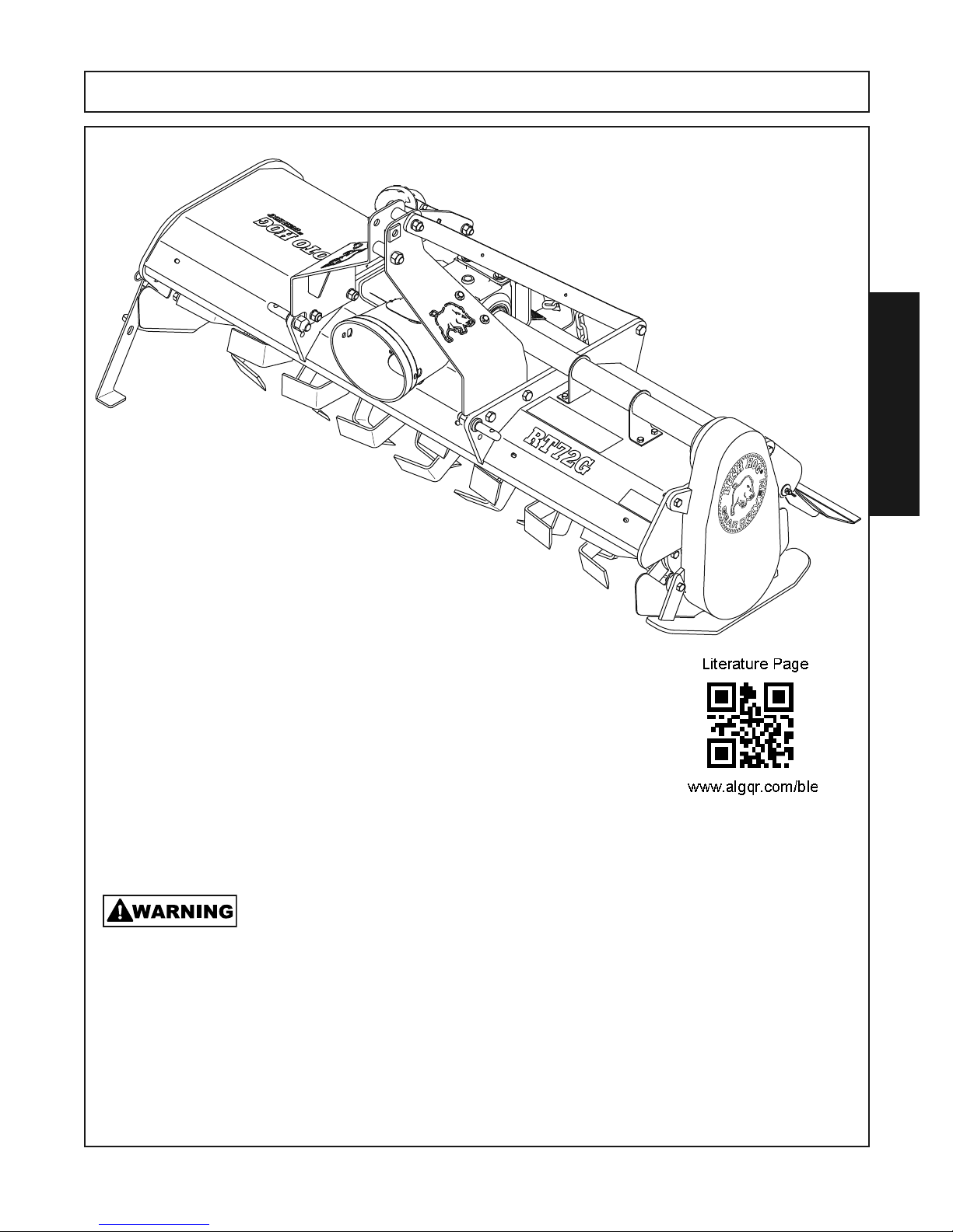
The RT60G requires between 25 HP - 45 HP with adequate front end weight.
The RT60GR requires between 25 HP - 45 HP with adequate front end weight.
The RT72G requires between 35 HP - 55 HP with adequate front end weight.
The RT72GR requires between 35 HP -55 HP with adequate front end weight.
The RT84G requires between 45 HP - 65 HP with adequate front end weight.
The RT84GR requires between 45 HP -65 HP with adequate front end weight.
At least 20% of the tractor’s total weight must be on the front tires with the implement lifted
to provide adequate traction at safe steering under good conditions. Slow down on hills,
rough terrain and curves.
Front and rear, and left and right are determined by the normal direction of travel (the same as on your automobile).
Carefully read the Operator’s Manual completely, understand the Safety Messages and instructions, and
know how to operate correctly both tractor and tiller.
RTG SERIES TILLER 05/16 Introduction Section 2-3
© 2015 Alamo Group.Inc.
Page 26

RTG SERIES TILLER 05/16 Introduction Section 2-4
© 2015 Alamo Group.Inc.
INTRODUCTION
INTRODUCTION
Attention Owner/Operator
BEFORE OPERATING THIS MACHINE:
1. Make sure at time of purchase the selling dealer registered the machines Warranty on line with Bush Hog.
NOTE: Warranties are honored only if completed “Owner Registration and Warranty” forms are received byAlamo
Group within thirty days of delivery of the implement.
2. Carefully read the Operator’s Manual, completely understand the Safety Messages and instructions, and
know how to operate correctly both the tractor and Tiller.
3. Record the Tiller Model and Serial Numbers on the Warranty page at the beginning of the Operator’s Manual.
Keep this as part of the permanent maintenance file for the Tiller.
Page 27

INTRODUCTION
LIMITED WARRANTY
●●●●●●●●●●●●●●●●●●●●●●●●●●●●●●●●●●●●●●●●●●●●●●●●●●●●●●
Bush Hog warrants to the original purchaser of any new RTG tiller, purchased from an authorized Bush Hog
dealer, that the equipment be free from defects in material and workmanship for a period of one (1) year for
non-commercial use with a (5) year Limited Center and Side Gear Box Warranty, (Years 1 & 2 parts and labor,
Years 3-5, parts only). For commercial and state and municipalities use, the warranty period is ninety (90)
days from date of retail sale. The obligation of Bush Hog to the purchaser under this warranty is limited to the
repair or replacement of defective parts.
Replacement or repair parts installed in the equipment covered by this limited warranty are warranted for
ninety (90) days from the date of purchase of such part or to the expiration of the applicable new equipment
warranty period, whichever occurs later. Warranted parts shall be provided at no cost to the user at an authorized Bush Hog dealer during regular working hours. Bush Hog reserves the right to inspect any equipment
or parts which are claimed to have been defective in material or workmanship
DISCLAIMER OF IMPLIED WARRANTY & CONSEQUENTIAL DAMAGES
Bush Hog’s obligation under this limited warranty, to the extent allowed by law, is in lieu of all warranties,implied
or expressed, INCLUDING IMPLIED WARRANTIES OF MERCHANTABILITY AND FITNESS FOR A PARTICULAR PURPOSE and any liability for incidental and consequential damages with respect to the sale or
use of the items warranted. Such incidental and consequential damages shall include but not be limited to:
transportation charges other than normal freight charges; cost of installation other than cost approved by Bush
Hog; duty; taxes; charges for normal service or adjustment; loss of crops or any other loss of income; rental
of substitute equipment, expenses due to loss, damage, detention or delay in the delivery of equipment or
parts resulting from acts beyond the control of Bush Hog.
.
INTRODUCTION
THIS LIMITED WARRANTY SHALL NOT APPLY:
1. To vendor items which carry their own warranties, such as engines, tires, and tubes.
2. If the unit has been subjected to misapplication, abuse, misuse, negligence, fire or other accident.
3. If parts not made or supplied by Bush Hog have been used in connection with the unit, if, in the sole judgement of Bush Hog such use affects its performance, stability or reliability.
4. If the unit has been altered or repaired outside of an authorized Bush Hog dealership in a manner which,
in the sole judgement of Bush Hog, affects its performance, stability or reliability.
5. To normal maintenance service and normal replacement items such as gearbox lubricant, hydraulic fluid,
worn blades, or to normal deterioration of such things as belts and exterior finish due to use or exposure.
6. To expendable or wear items such as teeth, chains, sprockets, belts, springs and any other items that in
the company’s sole judgement is a wear item.
NO EMPLOYEE OR REPRESENTATIVE OF BUSH HOG IS AUTHORIZED TO CHANGE THIS LIMITED
WARRANTY IN ANY WAY OR GRANT ANY OTHER WARRANTY UNLESS SUCH CHANGE IS MADE IN
WRITING AND SIGNED BY BUSH HOG’S SERVICE MANAGER, 2501 GRIFFIN AVE., SELMA, ALABAMA
36703.
●●●●●●●●●●●●●●●●●●●●●●●●●●●●●●●●●●●●●●●●●●●●●●●●●●●●●●
Record the model number, serial number and date
purchased. This information will be helpful to your
dealer if parts or service are required.
MAKE CERTAIN THE WARRANTY
HAS BEEN FILED WITH BUSH HOG
SELMA, ALABAMA
MODEL NUMBER:
SERIAL NUMBER:
DATE OF RETAIL SALE:
RTG SERIES TILLER 05/16 Introduction Section 2-5
© 2015 Alamo Group.Inc.
Page 28

Page 29

ASSEMBLY
SECTION
Assembly Section 3-1
Page 30
ASSEMBLY
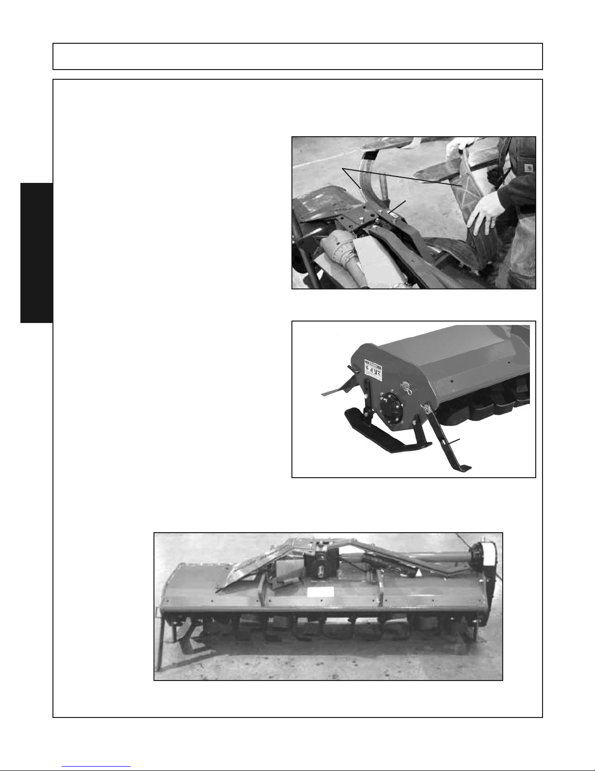
Bush Hog RTG series Tillers are shipped from the factory partially assemblied in a shipping crate and requires
some assembly before being placed into service.
Follow these instructions listed to safely remove the Tiller from the shipping crate and prepare for assembly.
1. With the tiller still in the shipping crate, place it
on a hard level surface.
2. Remove the crateing top and sides and discard.
3. Remove the driveshaft from the shipping
assembly and lay aside for installation later.
4. Insert a lifting strap in the gearbox mounting
frame.
ASSEMBLY
5. Carefully lift the tiller assembly from the
shipping pallet.
6. Remove parking stand from storage position
and place in parking position.
Lifting Strap
Gearbox
Mounting
Frame
7. Place tiller on hard level surface for assembly and remove lift strap.
RTG SERIES TILLER 05/16 Assembly Section 3-2
Parking Stand in
Park Position
© 2015 Alamo Group.Inc.
Page 31
ASSEMBLY
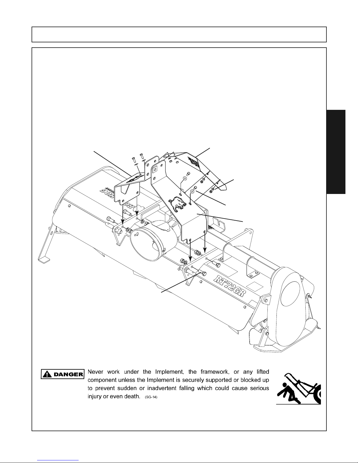
8. Carefully remove the “A” Frames, Mast Bars, “A”Frame Cover and bag of fasteners at-
tached to the top of the machine for shipping.
9. Attach the R.H. and L.H. “A” Frames to the Inside of the frame braces. From the bag of
fasteners use (4) 5/8” x 1-3/4” Gr. 5 capscrews, (4) 5/8” lockwashers & (4) 5/8” hex nuts.
Leave fasteners finger tight at this point.
10. Assemble the “A”Frame Cover to the inside of the “A” Frames using (4) 3/8” x 1” cap-
screws, (4) 3/8” flatwashers (on the outside of the “A” Frame against the slotted holes), (4)
3/8” lockwashers & (4) 3/8” hex nuts from the bag of fasteners.
ASSEMBLY
R.H. “A”Frame
5/8” x 1-3/4” Capscrew (4) Places
5/8” Lockwashers (4) Places
5/8” Hex Nuts (4) Places
“A” Frame Cover
3/8” Lockwasher () Places
3/8” Hex Nut (4) Places
3/8” x1” Capscrew (4) Places
3/8” Flatwashers (4) Places
L.H. “A”Frame
RTG SERIES TILLER 05/16 Assembly Section 3-3
© 2015 Alamo Group.Inc.
Page 32
ASSEMBLY
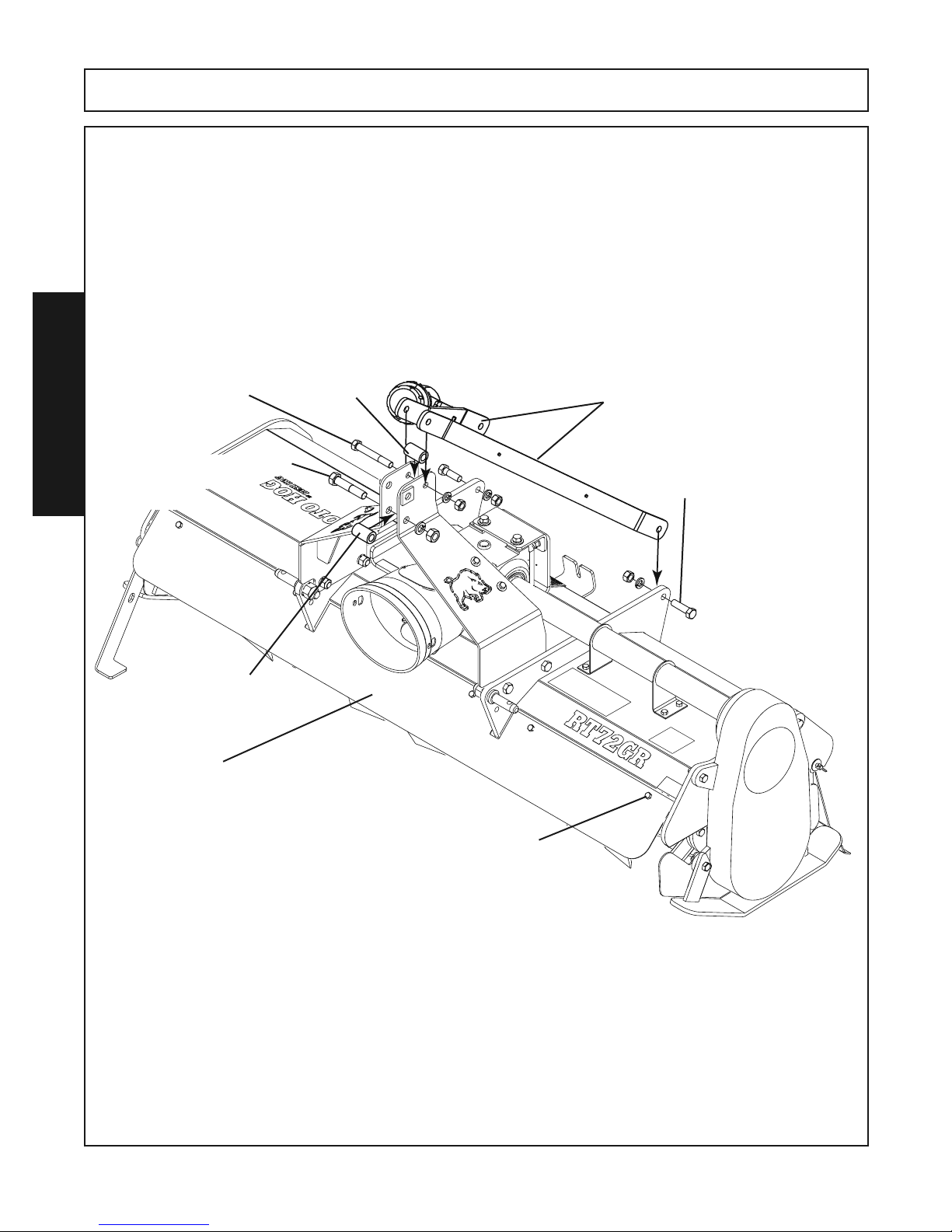
11. Attach the 2 Mast Bars to the inside of the frame braces using (2) 5/8” x 2” Gr.8 capscrews, (2) 5/8” Lockwashers, (2) 5/8” Hex Nuts.
12. Place the Mast Bars to the outside of the top rear hole of the”A” frame. Place a bushing (2” long x 1.25”
diameter) between the “A” frame, align holes. Fasten with a 5/8” x 4-1/2” Gr.5 capscrew, 5/8” lockwasher &
5/8” hex nut.
13.To the lower hole at the top front of the “A” Frame place a bushing (2” long x 1.25” diameter) between the
“A” frame, align holes and install a 3/4” x 3-3/4” Gr.5 capscrew,3/4” lockwasher & 3/4” hex nut.
14.Tighten ALL fasteners.
5/8” x 4-1/2” Gr.5 Capscrew
5/8” Lockwasher
5/8” HexNut
3/4” x 3-3/4” Gr.5 Capscrew
ASSEMBLY
3/4” Lockwasher
3/4” HexNut
Bushing
Metal Shield
Reverse Rotation Models Only
Bushing
Mast Bars
5/8” x 2” Gr.8 Capscrew (2 Places)
5/8” Lockwasher (2 Places)
5/8” Hex Nut (2 Places)
RTG60GR, RT72GR, RT84GR REVERSE ROTATION MODELS ONLY
Attach the metal shield to the front of the Tiller using (6) 3/8” x 1” Capscrews and (6) 3/8” Locknuts.
RTG SERIES TILLER 05/16 Assembly Section 3-4
© 2015 Alamo Group.Inc.
3/8” x 1” Capscrew (6) Places
3/8” Locknut (6) Places
Page 33
ASSEMBLY
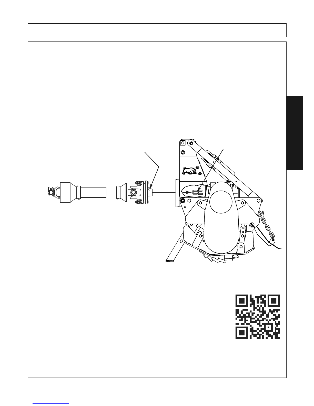
DRIVELINE ATTACHMENT
Before installing driveline to tiller, make sure all dirt, paint and grease are removed from the
gearbox shaft. To ease in the installation, a light coat of grease may be applied to the gear-
box shaft after cleaning.
1. Remove the M12-1.25 x 65 Capscrew, M12 Lockwasher and M12- 1.25 Hex Nut from
the slip clutch yoke end and retain for re-installation.
2. Slide slip clutch yoke end of driveline onto the gerabox shaft.
3. Align the hole in the yoke of the slip clutch with the groove around the gearbox shaft.
4. Place the M12-1.25 x 65 Capscrew through the yoke and through the groove in the shaft.
Attach the M12 Lockwasher and the M12 Hex Nut to the Capscrew and tighten.
Gearbox Shaft Groove
Slip Clutch Yoke Hole For
M12-1.25 x 65 Capscrew
M12 Lockwasher
M12 -1.25 Hex Nut
ASSEMBLY
IMPORTANT: Scan this QR Code with your smart phone to link to the ADMA Driveline
Safety Manual for more information on the safe use of a driveline during normal operation and maintenance. Or type in your internet browser the following web address:
www.algqr.com/dme
RTG SERIES TILLER 05/16 Assembly Section 3-5
© 2015 Alamo Group.Inc.
Page 34
LUBRICATION
ASSEMBLY
Important
This tiller is shipped from the factory WITHOUT oil in the gearboxes and without
grease in the grease fittings. THE UNIT MUST BE SERVICED BEFORE PUTTING IN OP-
ERATION.
NOTE: Use GL5-85W 140 or Triple Zero Grease which can be poured and has an “EP” Ex-
treme Pressure Additives in the Gearboxes. Use TYPE/Grade II grease at all Grease Fittings.
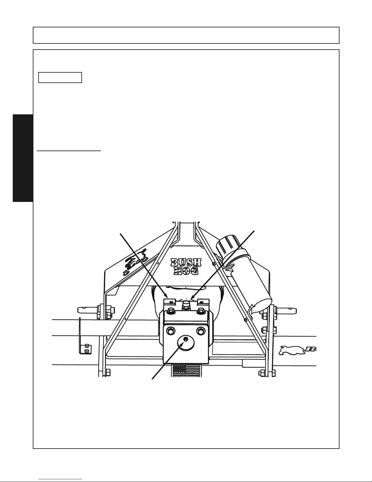
TOP GEARBOX
1. Remove the vent plug on the top of the gearbox and the small inspection plug at the rear
of the gearbox.
2. Pour the gear oil into the vent plug hole slowly until the oil starts to come out of the small
ASSEMBLY
hole at the rear. DO NOT OVER FILL THE GEARBOX!
3. Replaces the small Inspection Plug and the Vent Plug. Clean up any excess gear oil.
TOP GEARBOX
VENT PLUG LOCATION
Remove Vent Plug to
install gear oil. Re-install vent
plug when oil is at proper
level.
SMALL INSPECTION PLUG
Remove and fill with gear oil until oil
comes out this hole and then place the
plug back into the hole
RTG SERIES TILLER 05/16 Assembly Section 3-6
© Alamo Group.Inc.
.
Page 35
ASSEMBLY
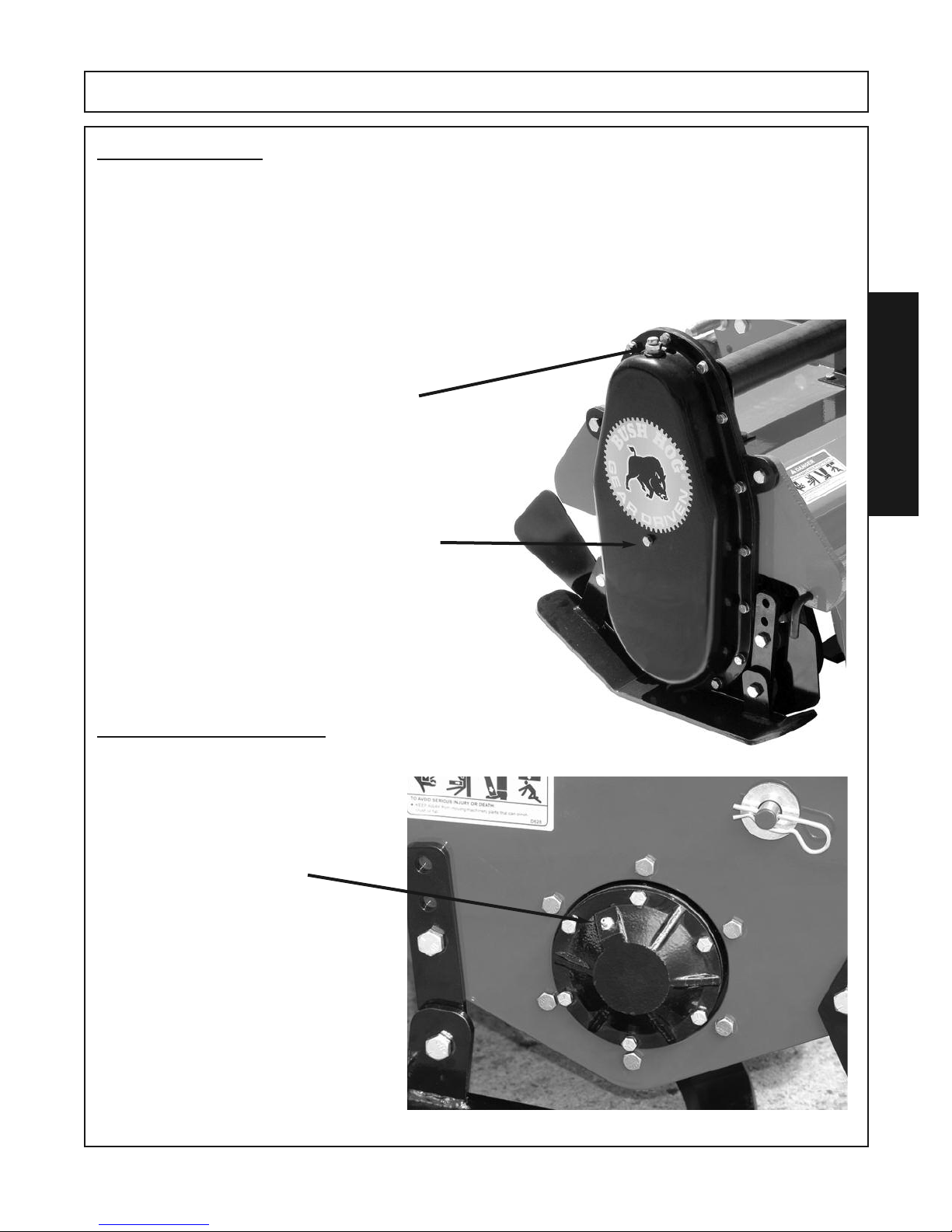
SIDE GEARBOX
1. Remove the vent plug on the top of the side gearbox and the small inspection plug at the
side of the gearbox.
2. Pour the gear oil into the vent plug hole slowly until the oil starts to come out of the small
hole on the side. DO NOT OVER FILL THE GEARBOX!
3. Replaces the small Inspection Plug and the Vent Plug. Clean up any excess gear oil.
VENT PLUG LOCATION
Remove Vent Plug to
install gear oil. Re-install vent
plug when oil is at proper
level.
SMALL INSPECTION PLUG
Remove and fill with gear oil until oil
comes out this hole and then place the
plug back into the hole
.
ASSEMBLY
OUTBOARD BEARING
Grease the Outboard Bearing located on the right hand side of the tiller.
GREASE FITTING
Outboard Bearing
RTG SERIES TILLER 05/16 Assembly Section 3-7
© Alamo Group.Inc.
Page 36
ASSEMBLY
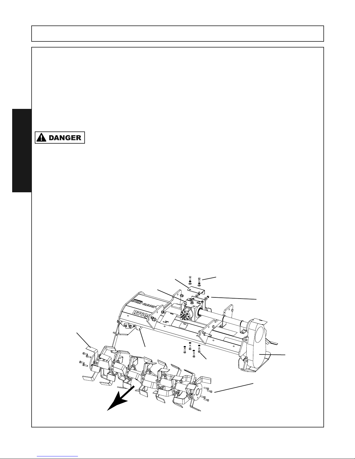
CONVERTING FROM STANDARD ROTATION TO REVERSE ROTATION
To convert the RTG Tiller, standard rotation to a reverse rotation will require the purchase of a Safety Shield to
prevent debris from entering the Operator area during operation. The required parts may be ordered from a
Bush Hog Dealer.
Required parts are as follows:
RTG60 Shield number 50075506
RTG72 Shield number 50075093
RTG84 Shield number 50075507
Attchment will require six (6) 3/8” x 1” Grade 5 bolts and six (6) 3/8” Locknuts.
Serious Injury or Death could occur if not taking the time to secure the Tiller to prevent the machine from falling or tipping while performing this procedure.
SAFETY FIRST
Park the Tiller on a hard level surface. Lower the parking stand and securely block the machine so it cannot tip
or roll over during this procedure.
ASSEMBLY
Disconnect the tiller from the tractor and move the tractor away from the tiller.
Note: In the following illustrations the lift frame and struts are not pictured for clarity. It is not necessary
to remove these items.
Step 1. Remove the driveline from the gearbox assembly. Remove the input shaft shield from the front of the
gearbox. Retain all fasteners for reinstallation.
Step 2. Remove the eight 1/2” x 1-3/4” bolts, hex nuts and lockwashers attaching the Tine Bar to the Side
Gearbox and the Right Side Hub. Carfully roll the Tine Bar from under the tiller mainframe out of the
way.
Step 3. Remove the 1/2” x 1-1/4” bolts, lockwashers and flatwashers attaching the Gearbox to the Gearbox
Plate. Loosen the 1/2” x 1-1/2” bolts, lockwashers and flatwashers attaching the Gearbox Plate to
the rear bracket.
Step 4. Remove the four 1/2” x 1-3/4” bolts and lockwashers located on the underside of the frame attaching
the Gearbox.
Gearbox Plate
Gearbox
Tine Bar Assembly
1/2” x 1-1/4” bolts
lockwashers
flatwashers
1/2” x 1-1/2” bolts
lockwashers
flatwashers
Hex Nuts
RTG SERIES TILLER 05/16 Assembly Section 3-8
© Alamo Group.Inc.
Right Side Hub
1/2” x 1-3/4” Bolts
Lockwashers
Side
Gearbox
1/2” x 1-3/4” Bolts
Lockwashers
Hex Nuts
(Both Ends)
Page 37
ASSEMBLY
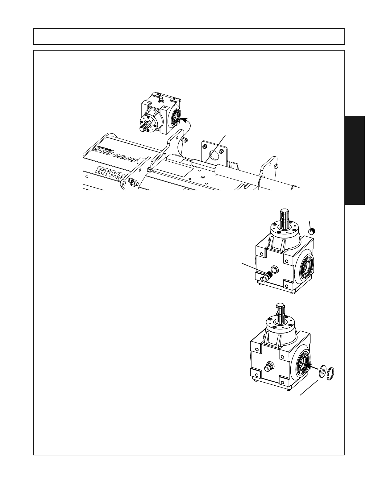
Step 5. Slide the Gearbox to the right untill it clears the hex driveshaft. Remove the Gearbox and place it on
a clean level surface with the back of the gearbox down and the input shaft pointing up. This is to
prevent the oil from running out while swapping the location of the Breather Plug and the oil plug on
the bottom of the box.
Slide the Gearbox to the right and remove
Hex Driveshaft
Step 6. Swap locations of the Vent Plug and the Oil Plug so the Vent
Plug is where the Oil Plug was and the Oil Plug is where the
Vent Plug was.
Vent
Plug
ASSEMBLY
Oil
Plug
Step 7. Remove the Snap Ring and Flatwasher from the inside of
the Hex Tube and reinstall to the opposite side. Place the
Flatwasher in first then secure in place with the Snap Ring.
RTG SERIES TILLER 05/16 Assembly Section 3-9
© Alamo Group.Inc.
Snap Ring and Flatwasher
Relocated From Other Side
Page 38
ASSEMBLY
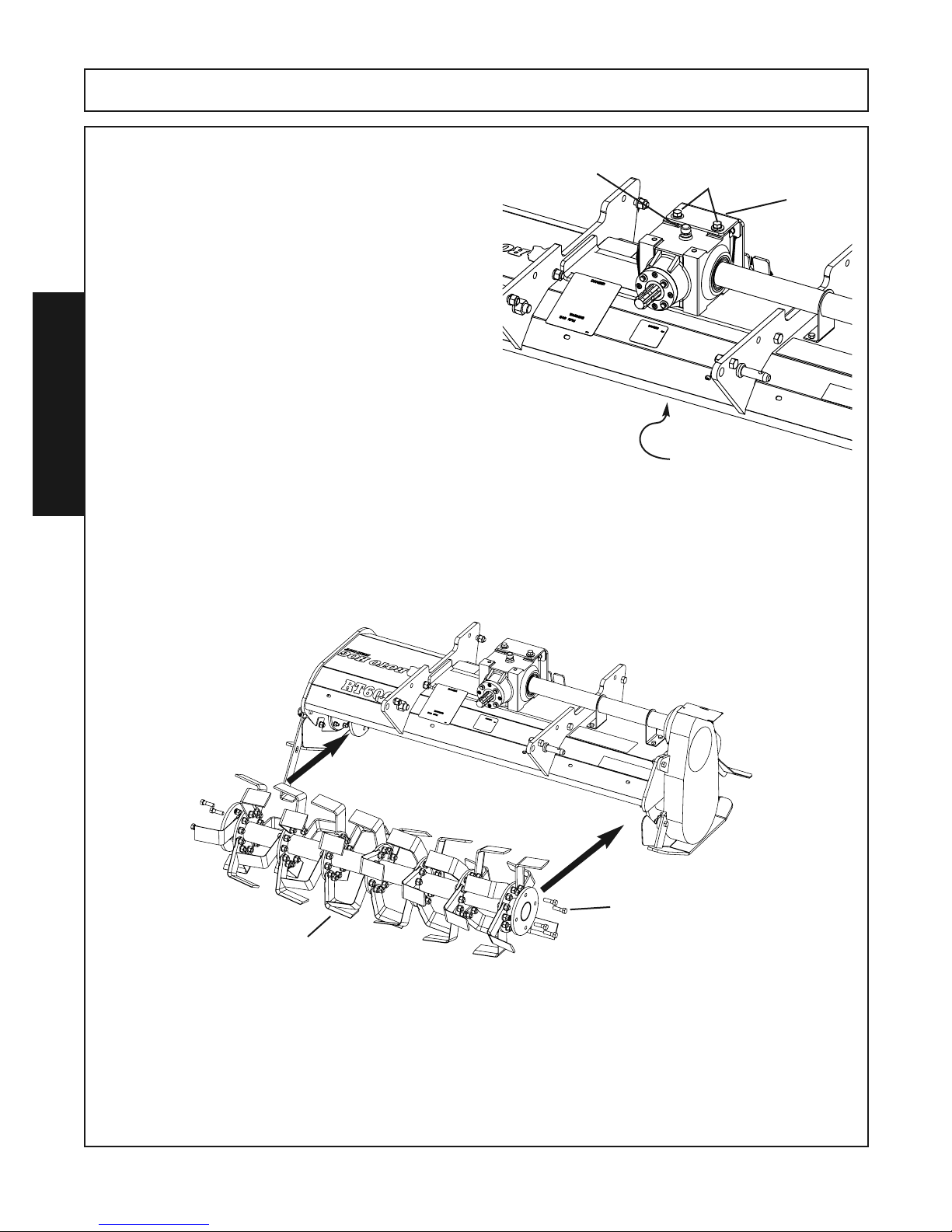
Step 8. Place the Gearbox on the mainframe with the
Vent plug on top. Move the Gearbox in place,
aligning the Hex Shaft and the Tube through the
Gearbox. Align the four holes in the mainframe
with the Gearbox mounting holes and reinstall
the four 1/2” x 1-3/4” bolts and lockwashers previously removed from this location.
Reattach the Gearbox Mounting Plate to the
Gearbox with the two 1/2” x 1-1/4” bolts, lockwashers and flatwashers previously removed.
Vent Plug
ASSEMBLY
Step 9. Turn the Tine Bar 180 degrees from the original position when removed. Reattach the Tine Bar As-
sembly to the Tiller using the eight 1/2” x 1-3/4” bolts, lockwashers and hex nuts.
(Note : If the fasteners are damage or worn from previous usage replace them.)
With the Tine Bar assembly in place, at ground level , the cutting edge of the tines should be toward
the front (facing forward).
1/2” x 1-1/4” Bolts
Lockwashers
Flatwashers
1/2” x 1-3/4” Bolts
Lockwashers
Located on the underside
Gearbox
Mounting
Plate
Cutting Edge
Facing Forward
RTG SERIES TILLER 05/16 Assembly Section 3-10
© Alamo Group.Inc.
1/2” x 1-3/4” Bolts
Lockwashers
Hex Nuts
(4) Per Side
Page 39
ASSEMBLY
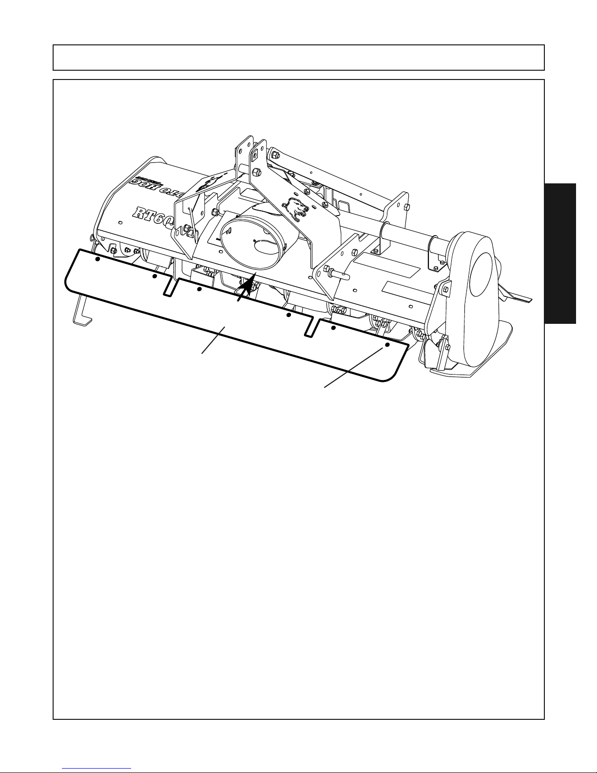
Step 10. Place the Shield to the front lip of the Tiller and align the holes with the slotted holes in the mainframe.
Use six 3/8” x 1” Grade 5 Bolts and 3/8” Locknuts to attach the Shield.
ASSEMBLY
Shield
3/8” x 1” Grade 5 Bolts and 3/8” Locknuts (6 each Required)
to attach the Shield
Step 11. Reattach the Gearbox Input Shaft Shield and Driveshaft to the Input Shaft.
NOTE: Before operating make sure all fasteners that have been removed and reinstalled are
tightened.
RTG SERIES TILLER 05/16 Assembly Section 3-11
© Alamo Group.Inc.
Page 40

Page 41

OPERATION
SECTION
Operation Section 4-1
Page 42

OPERATION
BUSH HOG RTG SERIES ROTARY TILLER
OPERATING INSTRUCTIONS
The Tiller is manufactured with quality material by skilled workers. This implement is ideal in
horticultural, agricultural, or commercial applications, especially for landscapers, rental yards,
vineyards, vegetable farms, and nurseries. The implement is equipped with protective deflectors to prevent objects being thrown from the implement by the blades, however, no
shielding is 100% effective. All shields, guards, and deflectors equipped on the unit must be
maintained on the implement in good operational condition.
It is the operator’s responsibility to be knowledgeable of all potential operating hazards and
to take every reasonable precaution to ensure oneself, others, animals, and property are not
injured or damaged by the implement, tractor, or a thrown object. Do not operate the implement if passersby, pets, livestock, or property are directly in front or to the rear of the unit.
OPERATION
This section of the Operator’s Manual is designed to familiarize, instruct, and educate safe
and proper implement use to the operator. Pictures contained in this section are intended to
be used as a visual aid to assist in explaining the operation of a implement tiller. Some pictures may show shields removed for purposes of clarity. NEVER OPERATE this implement
without all shields in place and in good operational condition. The operator must be familiar
with the implement and tractor operation and all associated safety practices before operating
the implement and tractor. Proper operation of implement, as detailed in this annual, will
help ensure years of safe and satisfactory use of the implement.
IMPORTANT: To avoid implement damage, re torque all bolts after the first 10 hours of operation. Refer to the Torque Chart at the end of the Maintenance Section to ensure bolts are
properly tightened.
READ AND UNDERSTAND THE ENTIRE OPERATING INSTRUCTIONS AND SAFETY
SECTION OF THIS MANUAL AND THE TRACTOR MANUAL BEFORE ATTEMPTING TO
USE THE TRACTOR AND IMPLEMENT. If you do not understand any of the instructions,
contact your nearest authorized dealer for a full explanation. Pay close attention to all safety
signs and safety messages contained in this manual and those affixed to the implement and
tractor. OPS-U- 0001
READ, UNDERSTAND, and FOLLOW the Safety Messages. Serious injury or death may
occur unless care is taken to follow the warnings and instructions stated in the Safety Messages. Always use good common sense to avoid hazards.
RTG SERIES TILLER 05/16 Operation Section 4-2
© 2015 Alamo Group.Inc.
Page 43
OPERATION
STANDARD EQUIPMENT and SPECIFICATIONS
RTG SERIES RT60G RT72G RT84G
RT60GR RT72GR RT84GR
Working Width 59“ 70-1/2” 82-1/2”
Overall Width 66” 78” 90”
Type of Knives “L” “L” “L”
Knives Per Flange 666
Number of Flanges 7911
Tilling Depth *7-1/2” *7-1/2” *7-1/2”
Skid Shoe Settings 333
Rated Rotor Speed 211 RPM 211 RPM 211 RPM
Gearbox Housing Cast Cast Cast
Deck Thickness .1345” .1345” .1345”
End Plate Thickness .50” .50” .50”
OPERATION
Required Tractor HP 25-45HP 35-55 HP 45-65 HP
Driveline Size Cat 4 Cat 4 Cat 4
Gearbox Protection Slip Clutch Slip Clutch Slip Clutch
Rotor Drive Type Gear Driven Gear Driven Gear Driven
Hitch Cat 1 & Cat 1QH Cat 1 & Cat 1QH Cat 1 & Cat 1 QH
Cat 2 & Cat 2 QH
*Requires Multiple Passes
Operating this implement in an application for which it is not designed and/or operating
the implement with the wrong size Tractor can cause implement component damage and
equipment failure resulting in possible serious injury or death.
RTG SERIES TILLER 05/16 Operation Section 4-3
© 2015 Alamo Group.Inc
.
Page 44
OPERATION
OPERATION
RTG SERIES TILLER 05/16 Operation Section 4-4
© 2015 Alamo Group.Inc.
Page 45
OPERATION
OPERATION
RTG SERIES TILLER 05/16 Operation Section 4-5
© 2015 Alamo Group.Inc.
Page 46
OPERATION
OPERATION
RTG SERIES TILLER 05/16 Operation Section 4-6
© 2015 Alamo Group.Inc.
Page 47
OPERATION
OPERATION
RTG SERIES TILLER 05/16 Operation Section 4-7
© 2015 Alamo Group.Inc.
Page 48
OPERATION
OPERATION
RTG SERIES TILLER 05/16 Operation Section 4-8
© 2015 Alamo Group.Inc.
Page 49
OPERATION
OPERATION
RTG SERIES TILLER 05/16 Operation Section 4-9
© 2015 Alamo Group.Inc.
Page 50
OPERATION
OPERATION
RTG SERIES TILLER 05/16 Operation Section 4-10
© 2015 Alamo Group.Inc.
Page 51
OPERATION
OPERATION
RTG SERIES TILLER 05/16 Operation Section 4-11
© Alamo Group.Inc.
Page 52
OPERATION
OPERATION
RTG SERIES TILLER 05/16 Operation Section 4-12
© Alamo Group.Inc.
Page 53
OPERATION
OPERATION
RTG SERIES TILLER 05/16 Operation Section 4-13
© Alamo Group.Inc.
Page 54
OPERATION
OPERATION
RTG SERIES TILLER 05/16 Operation 4-14
© Alamo Group.Inc.
Page 55
OPERATION
OPERATION
RTG SERIES TILLER 05/16 Opeartion 4-15
© Alamo Group.Inc.
Page 56
OPERATION
OPERATION
RTG SERIES TILLER 05/16 Operation Section 4-16
© Alamo Group.Inc.
Page 57
OPERATION
OPERATION
RTG SERIES TILLER 05/16 Operation Section 4-17
© Alamo Group.Inc.
Page 58
OPERATION
9. OPERATING THE TRACTOR AND IMPLEMENT
THE OPERATOR MUST COMPLETELY UNDERSTAND HOW TO OPERATE THE TRACTOR AND
IMPLEMENT AND ALL CONTROLS BEFORE ATTEMPTING TO OPERATE.
The operator must read and understand the Safety and Operation Sections of the implement and tractor
operator’s manuals. These manuals must be read and explained to any operator who cannot read.
Never allow someone to operate the implement and tractor without complete operating instructions.
Before starting any operation, the operator must become familiar with the area to be worked in and
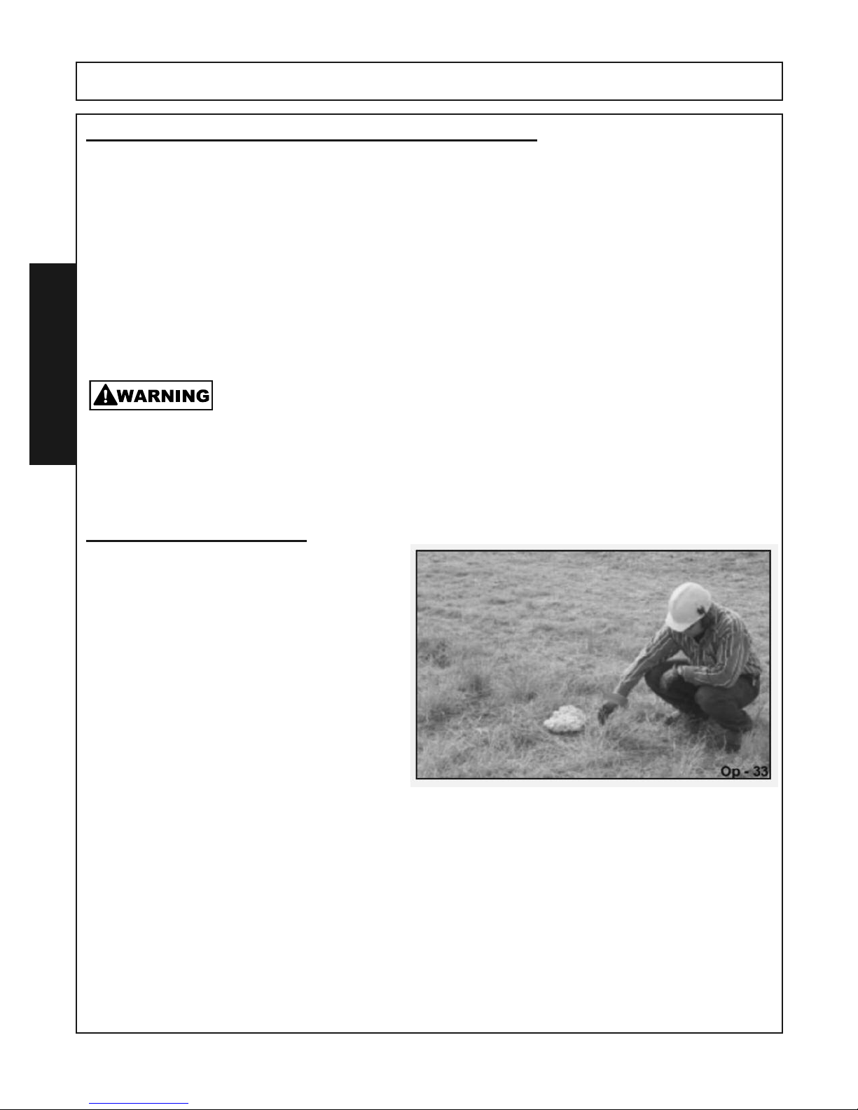
any obstacles and hazards contained within to ensure safety to the operator, bystanders, and equipment. Special attention should be paid to foreign debris, rough terrain, steep slopes, and passersby
and animals in the area
OPERATION
. OPS U 0015
Many varied objects, such as wire, cable, rope, or chains, can become entangled
in the rotating parts of the Implement. These objects could then swing outside the
housing at greater velocities than the blades. Such a situation is extremely hazardous and could result in serious injury or even death. Inspect the area for such
objects before working in tue area. Remove any such objects from the site. Never
allow the implement to contact
such objects. (STL-6)
Foreign Debris Hazards
Before operating, inspect the area to make sure
there are no foreign objects that the implement
knives could hit or become entangled with. Remove all foreign objects and debris. If objects are
too big to remove, mark them clearly and be sure
to prevent the implement blades from contacting
them.
If you hit a solid object or foreign debris, stop the
implement and tractor at once. Immediately idle
the engine speed and disengage the PTO. Wait
for all implement rotating motion to stop, then
raise the implement and move the tractor and
implement off the object. Inspect the area and
remove, or mark the location of the debris. Inspect the condition of the implement and make
any needed repairs immediately. Make sure the
knives are not damaged and the carrier is balanced before resuming operation.
Always wear your seat belt securely fastened and only operate the tractor and implement with the
ROPS in the raised position. If the tractor or implement hits a tree stump, rock, or bump, a sudden
movement could throw you off of the seat and under the tractor and/or implement. The seat belt is your
best protection from falling off the tractor and the ROPS provides protection from being crushed during
a tractor roll-over. OPS-T-0003
RTG SERIES TILLER 05/16 Operation Section 4-18
© Alamo Group.Inc.
Page 59
OPERATION
OPERATION
RTG SERIES TILLER 05/16 Operation Section 4- 19
© Alamo Group.Inc.
Page 60
OPERATION
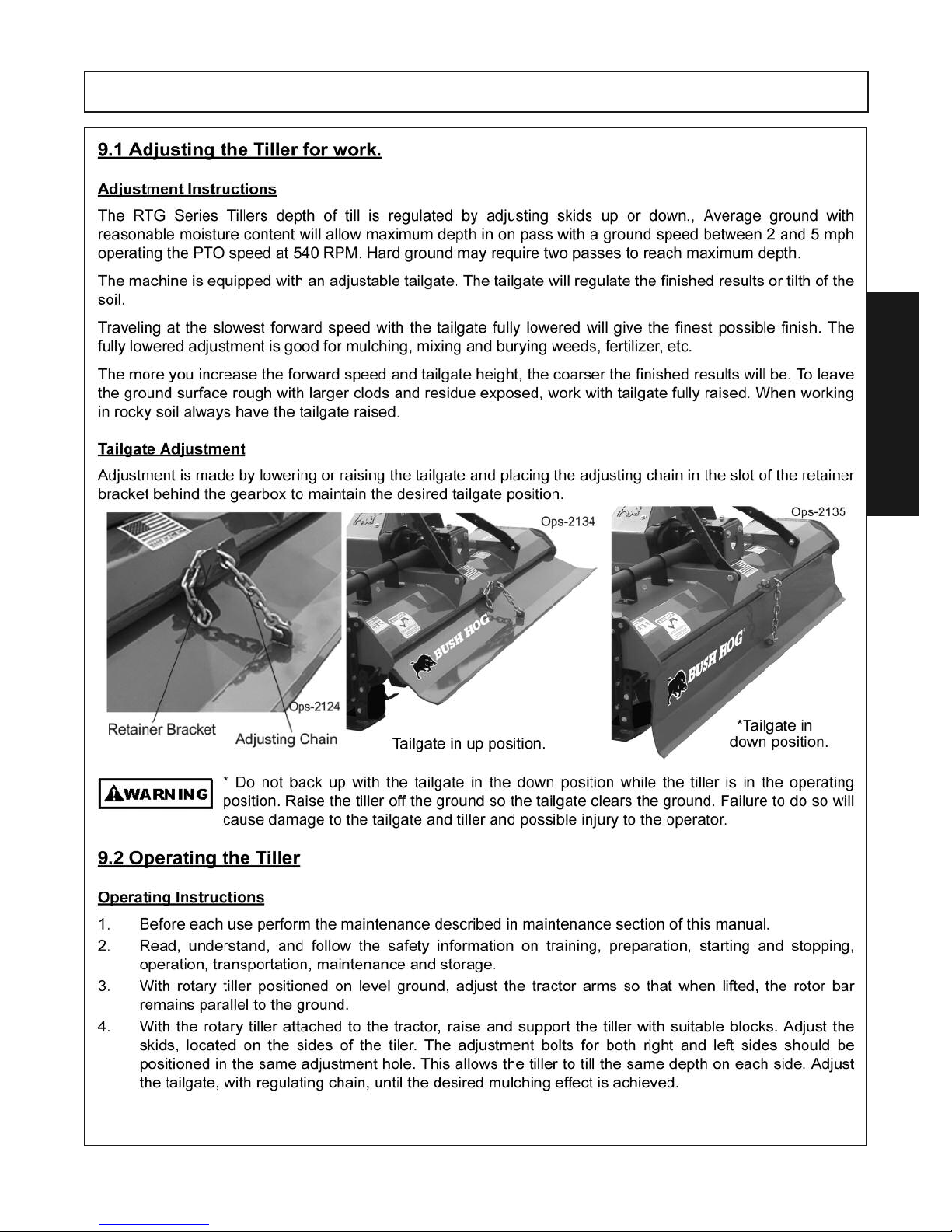
Never attempt to adjust the rotary tiller while the tractor is running.
5. Raise the tiller and remove the blocks. Lower the tiller to the ground.
6. With the tractor at idle RPM and the tiller lifted off of the ground, engage PTO and slowly advance
throttle to 540 PTO RPM.
NOTE: Rotary tiller is designed to run at 540 PTO RPM only.
7. Select a low gear for the tractor and begin to move forward. Tractor ground speed is to be controlled by gear selection only and not engine speed. As the tractor moves forward, slowly lower
the tiller down. Allow the tiller tines to gradually engage the ground.
NOTE: Do not allow the tractor engine or rotary tiller to bog down or stall. This causes undue wear
and tear on the tiller and tractor. If this continues to happen reduce ground speed and raise tilling
depth of rotary tiller. Never attempt to remove objects from the rotor bar until the tractor has been
shut down and the tiller tines have completely stopped.
OPERATION
Never travel at a fast ground speed while using the tiller, this could damage
it. Never attempt to turn the tractor or travel in reverse with the PTO engaged
and the tiller in the ground. Always raise the tiller out of the ground when backing up or attempting to turn. Failure to do so may cause damage to the tiller.
8. After each use clean all debris from the tiller tines. Replace any missing or illegible safety decals.
Inspect for any damaged or worn parts and replace before next use. Store rotary tiller in a dry environment.
Extreme care should be taken when operating near loose objects such as gravel,
rocks, wire, and other debris. Inspect the area before tilling. Foreign objects
should be removed from the site to prevent machine damage and/or bodily injury or even death. Any
objects that cannot be removed must be clearly marked and carefully avoided by the operator. Stop
operating immediately if blades strike a foreign object. Repair all damage and make certain rotor
and blades are in good condition before resuming operation.
(STL 5)
9.3 Bystanders/Passersby Precautions
If a bystander comes within 300 feet of the tractor while the implement is being operated, stop the
tractor at once, idle the engine and disengage the PTO. Do not engage the PTO again until all bystanders are well past the 300 foot distance. OPS T 0004
9.4 Engaging the Power Take Off (PTO)
Before engaging the PTO, make certain that the area is clear of bystanders and passersby. The implement must be completely lowered and the deck positioned at a safe operating height. NEVER
engage the PTO with the implement in the raised position. Set the tractor engine speed at approximately 1,000 RPM before engaging the PTO. Shift the PTO control to the on position, and slowly increase the engine speed until the PTO is operating at the rated speed. If you hear unusual noises or
see or feel abnormal vibrations, disengage the PTO immediately. Inspect the implement to determine
the cause of the noise or vibration and repair the abnormality. OPS-U- 0027
RTG SERIES TILLER 05/16 Operation Section 4-20
© Alamo Group.Inc.
Page 61
OPERATION
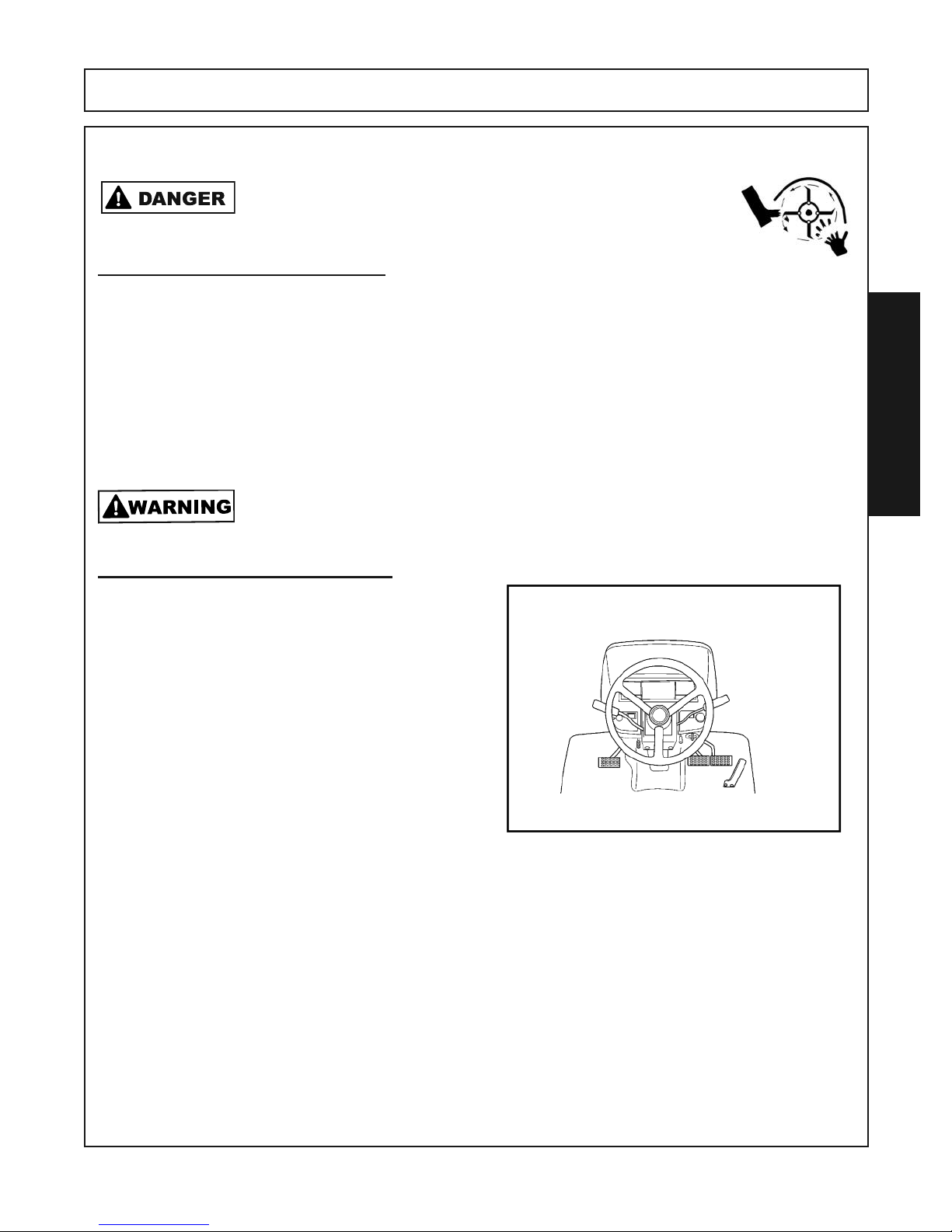
Do not put hands or feet under Tiller deck. Blade Contact can result in
serious injury or even death. Stay away until all motion has stopped and
the decks are securely blocked up.
9.5 PTO RPM and Ground Speed
Ground speed for operating will depend upon the type of cultivation. Recommended speed for efficient implement
performance is between 2 and 5 mph. Operate the implement at its full rated PTO speed to maintain knife speed
for a clean operation. Refer to the tractor operator’s manual or the tractor instrument panel for the engine speed
and gear to provide the required PTO and desired ground speed. Make sure that the implement is operating at
its full rated speed before entering the area. If it becomes necessary to temporarily regulate engine speed, increase or decrease the throttle gradually. Ground speed is achieved by transmission gear selection and not by
the engine operating speed. The operator may be required to experiment with several gear range combinations
to determine the best gear and range which provides the most ideal performance from the implement and most
efficient tractor operation. As the severity of operating conditions increase, the ground speed should be decreased
by selecting a lower gear to maintain the proper operating PTO speed
Do not exceed the rated PTO speed for the Implement. Excessive PTO speeds can
cause Implement driveline or blade failures resulting in serious injury or death.
(STL 3)
. OPS T 0006
(SG 26)
OPERATION
9.6 Shutting Down the Implement
To shut down the implement, first bring the tractor
to a complete stop. Then slow down the implement
by reducing the engine speed before disengaging
the PTO. Wait for all motion to stop before proceeding to drive or shut down the tractor.
Park the tractor on a level surface, place the transmission in park or neutral and apply the parking
brake, lower the attached implement to the ground,
shut down the engine, remove the key, and wait for
all motion to come to a complete stop before exiting
the tractor.
OPS T 0007
RTG SERIES TILLER 05/16 Operation Section 4-21
© Alamo Group.Inc.
Page 62
OPERATION
10. DISCONNECTING THE IMPLEMENT FROM THE TRACTOR
Before disconnecting the implement, the PTO must be disengaged and knife rotation at a complete stop. Move
the implement to a level storage location and lower it to the ground. If the implement is not resting securely on
the ground, block the implement up securely before attempting to disconnect it from the tractor.
Use extreme care to keep feet and hands from under the implement and clear of any pinch points caused by
the tractor hitch arms and implement pins.
Never stand or allow another person to stand between a running Tractor and the Implement
when disconnecting the Implement from the Tractor 3-point hitch
Always shut the Tractor completely down, place the transmission in park, and set the parking brake before you or anyone else attempts to connect or disconnect the Implement and
Tractor hitches. (S3PT 15)
OPERATION
To disconnect the implement, first extend the tractor 3-point hitch top link to remove tension on the top link hitch
pin. When the pin is loose and easy to rotate, remove the pin from the implement. Next remove both lower hitch
pins.
OPS T 0008
.
After disconnecting the 3-lift points, remove the implement driveline from the tractor PTO shaft. Lay the driveline
down carefully to avoid damaging the driveline or its shield. Do not let the driveline fall into mud or dirt, which
can contaminate the bearing and shorten the life of the driveline.
RTG SERIES TILLER 05/16 Operation Section 4-22
© Alamo Group.Inc.
Page 63
OPERATION
11. IMPLEMENT STORAGE
Properly preparing and storing the implement at the end of the season is critical to maintaining its appearance and to help
ensure years of dependable service. The following are suggested storage procedures:
• Thoroughly clean all debris off the implement to prevent damage from rotting grass and standing water.
• Lubricate all implement grease points and fill gearbox oil levels as detailed in the maintenance section.
• Tighten all bolts and pins to the recommended torque.
• Check the implement for worn and damaged parts. Perform repairs and make replacements immediately so that the implement will be ready for use at the start of the next season.
• Store the implement in a clean, dry place with the implement housing resting securely on blocks or at ground level.
• Keep the driveline yoke from sitting in water, dirt and other contaminants.
• Use spray touch-up enamel where necessary to prevent rust and maintain the appearance of the implement.
It is critical that driveline clutches slip when an obstacle or heavy load is encountered to avoid implement and/
or tractor damage. If the implement sits outside for an extended period of time or is exposed to rain and/or
humid air, the clutch lining plates must be inspected to ensure they are not frozen together from rust or corrosion.
If the implement has been exposed to such conditions, at the start of each operating season, and any time it is
suspected that the slip clutch plates may be frozen together, readjust the slip clutch as detailed in Seasonal
Clutch Maintenance of the maintenance section in this manual.
OPS T 0010
OPERATION
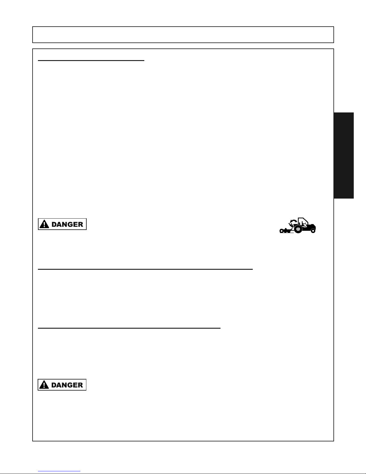
Never allow children or other persons to ride on the Tractor or Implement.
Falling off can result in serious injury or death.
(SG-10)
12. TRANSPORTING THE TRACTOR AND IMPLEMENT
Inherent hazards of operating the tractor and implement and the possibility of accidents are not left behind when you finish
working in an area. Therefore, the operator must employ good judgement and safe operation practices when transporting
the tractor and implement between locations. By using good judgement and following safe transport procedures, the possibility
of accidents while moving between locations can be substantially minimized.
OPS U 0017
13. DRIVING THE TRACTOR AND IMPLEMENT
Safe tractor transport requires the operator possess a thorough knowledge of the model being operated and precautions to take while driving with an attached implement. Ensure the tractor has the capacity to handle the weight
of the implement and the tractor operating controls are set for safe transport. To ensure safety while driving the
tractor with an attached implement, review the following.
Never run the Tractor engine in a closed building or without adequate ventilation. The exhaust
fumes can be hazardous to your health. (SG-23)
OPS U 0012
RTG SERIES TILLER 05/16 Operation Section 4-23
© Alamo Group.Inc.
Page 64
OPERATION
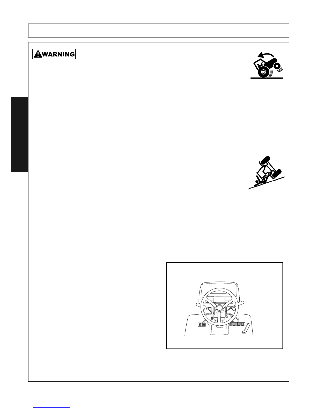
Transport only at speeds where you can maintain control of the
equipment. Serious accidents and injuries can result from operating
this equipment at high speeds. Understand the Tractor and Implement and how it handles before transporting on streets and highways. Make sure the Tractor steering and
brakes are in good condition and operate properly.
Before transporting the Tractor and Implement, determine the proper transport speeds
for you and the equipment. Make sure you abide by the following rules:
Test the tractor at a slow speed and increase the speed slowly. Apply the Brakes
smoothly to determine the stopping characteristics of the Tractor and Implement. As
you increase the speed of the Tractor the stopping distance increases. Determine the
maximum transport speed not to exceed 20 mph (30 kph) for transporting this equipment.
Test the equipment at a slow speed in turns. Increase the speed through the turn only
OPERATION
after you determine that the equipment can be operated at a higher speed. Use extreme
care and reduce your speed when turning sharply to prevent the tractor and implement
from turning over. Determine the maximum turning speed for you and this equipment
before operating on roads or uneven ground.
Only transport the Tractor and Implement at the speeds which allow you to properly
control the equipment.
Be aware of the operating conditions. Do not operate the Tractor with weak or faulty
brakes or worn tires. When operating down a hill or on wet or rain slick roads, the braking distance increases: use extreme care and reduce your speed. When operating in
traffic always use the Tractor’s flashing warning lights and reduce your speed. Be aware
of traffic around you and watch out for the other guy.
Before transporting the tractor and implement, idle
the tractor engine, disengage the PTO and wait
for all implement moving parts to come to a complete stop. Once all implement parts are completely stopped, raise the implement to transport
height.
NOTE: When raising the implement, maintain 1”
clearance between the driveline and implement
deck. If additional implement deck height is
needed for transport, disconnect the driveline from
the tractor and secure its end to the implement
deck. The implement can then be raised to the
maximum lift height.
OPS T 0011
(SG 19)
RTG SERIES TILLER 05/16 Operation Section 4-24
© Alamo Group.Inc.
Page 65

OPERATION
13.1 Brake and Differential Lock Setting
Make sure the tractor brakes are in good operating
condition. Tractor brakes can be set to operate independently allowing single rear wheel braking action or locked together to provide simultaneous
rear wheel braking. FOR MOST DRIVING AND
OPERATING CONDITIONS, THE BRAKE PEDALS SHOULD BE LOCKED TOGETHER TO
PROVIDE THE MOST EFFECTIVE BRAKING
ACTION.
Always disengage the tractor differential lock when
turning. When engaged the differential lock will
prevent or limit the tractor from turning. During normal cutting conditions, locking the differential provides no benefit and should not be used.
OPS U 0013
Be aware of the operating conditions. Do not operate the Tractor with weak or faulty
brakes. When operating down a hill or on wet or rain slick roads, the braking distance
increases; use extreme care and reduce your speed in these conditions. When operating in traffic, always use the Tractor’s flashing warning lights and reduce your
speed. Be aware of traffic around you and watch out for the other guy.
OPERATION
If the tractor’s hydraulic pump is not independent of the
tractor PTO, or if the tractor PTO has to be run to have hydraulic power, disconnect the implement driveline from the
tractor PTO output shaft. Secure the driveline to the implement deck to prevent driveline damage or loss during
transport. OPS-T-0012
RTG SERIES TILLER 05/16 Operation Section 4-25
© Alamo Group.Inc.
Page 66
OPERATION
13.2 Transporting on Public Roadways
Extreme caution should be used when transporting the tractor and implement on public roadways.
The tractor must be equipped with all required safety warning features including a SMV emblem and
flashing warning lights to alert drivers of the tractor’s presence. Remember that roadways are primarily
designed for automotive drivers and most drivers will not be looking out for you, therefore, you must
look out for them. Check your side view mirrors frequently and remember that vehicles will approach
quickly because of the tractor’s slower speed. Be extremely cautious when the piece of equipment
that you are towing is wider than the tractor tire width and/or extends beyond your lane of the road.
Make sure that a proper size safety tow chain is secured between the tractor and implement before
entering a public road.
OPERATION
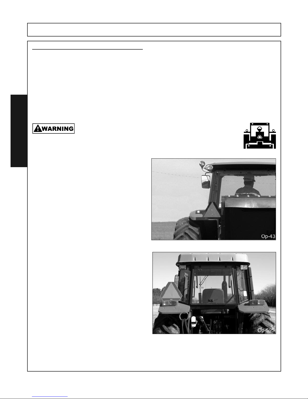
The SMV (Slow-Moving Vehicle) emblem is universal symbol used to alert drivers of the presence of equipment traveling on roadways at a
slow speed. SMV signs are a triangular bright orange with reflective red trim for both easy day
and night visibility. Make sure the SMV sign is
clean and visible from the rear of the unit before
transporting the tractor and implement on a public roadway.
Replace the SMV emblem if faded, damaged, or
no longer reflective.
OPS U 0019
Make certain that the “Slow Moving Vehicle” (SMV) sign is installed
in such a way as to be clearly visible and legible. When transporting
the Equipment use the Tractor flashing warning lights and follow all
local traffic regulations.
OPS U 0020
(SG 6)
Make sure that all tractor flashing warning lights,
headlights, and brake/tail lights are functioning
properly before proceeding onto public roads.
While newer model tractors have plenty of lighting to provide warning signals and operating
lighting, most older models are only equipped
with operating lights.
Consult an authorized tractor dealer for lighting
kits and modifications available to upgrade the
lighting on older tractor models.
RTG SERIES TILLER 05/16 Operation Section 4-26
© Alamo Group.Inc.
OPS U 0021
Page 67
OPERATION
When operating on public roads, have consideration for other road users. Pull to the side of the road
occasionally to allow all following traffic to pass. Do not exceed the legal speed limit set in your country
for agricultural tractors. Always stay alert when transporting the tractor and implement on public roads.
Use caution and reduce speed if other vehicles or pedestrians are in the area.
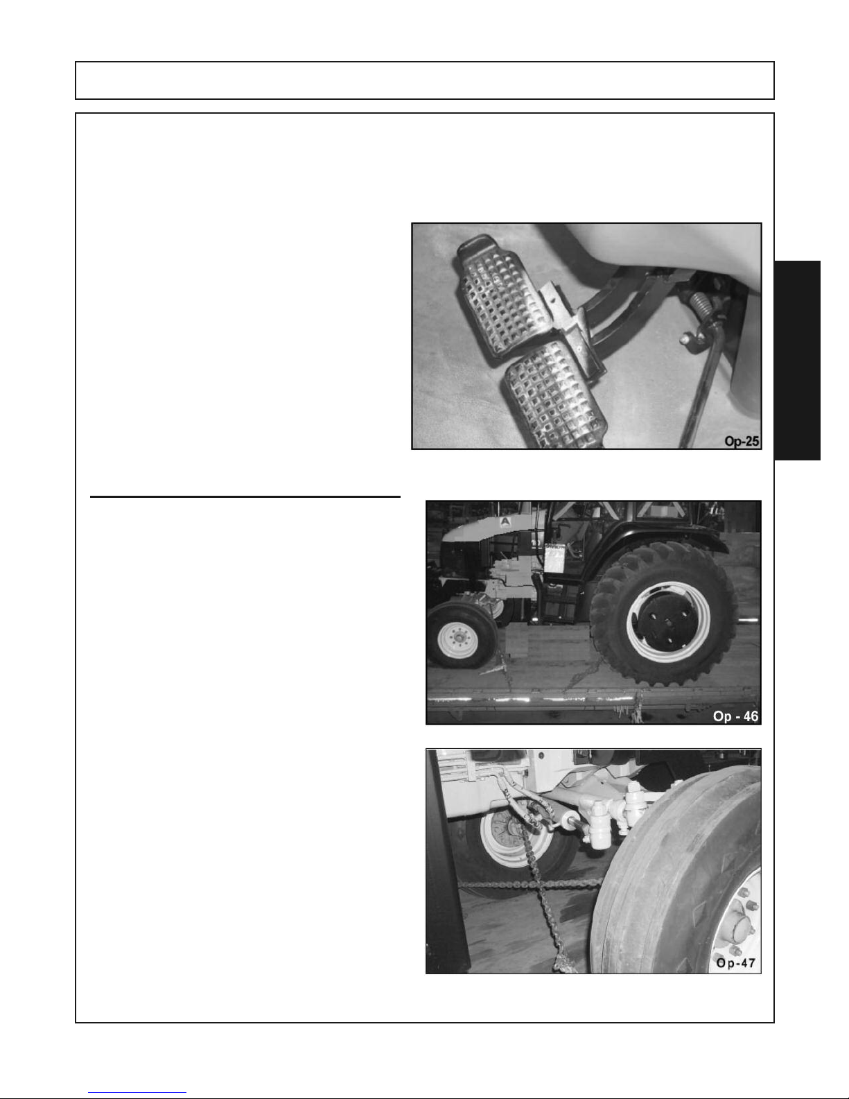
Reduce speed before turning or applying the
brakes.Ensure that both brake pedals are
locked together when operating on public roads.
OPS U 0023
OPS T 0013
OPERATION
13.3 Hauling the Tractor and Implement
Before transporting a loaded tractor and implement, measure the height and width dimensions
and gross weight of the complete loaded unit. Ensure that the load will be in compliance with the
legal limits set for the areas that will be traveled
through.
Use adequately sized and rated trailers and equipment to transport the tractor and implement. Consult an authorized dealer to determine the proper
equipment required. Using adequately sized
chains, heavy duty straps, cables and/or binders,
securely tie down both the front and rear of the
tractor utilizing the proper tie down locations as
specified by the tractor manufacturer.
OPS U 0025
OPS U 0024
RTG SERIES TILLER 05/16 Operation Section 4-27
© Alamo Group.Inc.
Page 68

OPERATION
14. TROUBLESHOOTING GUIDE
PROBLEM POSSIBLE CAUSE POSSIBLE REMEDY
Machine makes intermittent Loose knives Tighten knives
clicking noise Gear tooth damaged Replace damaged gear
PTO Vibrates Worn universal joint Replace universal joint
Machine lifted too high Lower machine and readjust
tractor lift stop
Excessive trash wrapped Remove trash
on rotor
Gearbox noise is noticeable May be normal or new machine Allow time for break-in
OPERATION
and constant Low oil level Add oil
Worn gears Replace gears
Rotors stop turning Slip clutch slipping Reduce load to Tiller or
Adjust slip clutch
Broken Gear /Gears Replace Gears
Machine skip or leaves Badly worn blades Replace worn blades
crop residue Slip clutch slipping Adjust slip clutch or
reduce load
Ground speed too fast Reduce ground speed
for conditions
Machine smells hot or Trash wrapped around Remove trash
begins to smoke drive components
Low oil level in gearbox Add oil
Slip clutch slipping Reduce load to machine or
adjust slip clutch
Oil leaking from gearbox Damaged seals Replace seals
Gearbox overfilled Drain to proper level (1/2 full)
RTG SERIES TILLER 05/16 Operation Section 4-28
© Alamo Group.Inc.
Page 69

MAINTENANCE
SECTION
Maintenance Section 5-1
Page 70
MAINTENANCE
Before operating your Tiller, make sure it is properly lubricated and thoroughly inspected. Only a minimum of time and effort is required to regularly lubricate and maintain this machine to provide long life and trouble free operation.
Always disengage the PTO before raising the Tiller for transporting or
making adjustments.
LUBRICATION INFORMATION
Do not let excess grease collect on or around parts, particularly when operating in sandy
areas. Severe or unusual conditions may require more frequent lubrication.
Use an SAE multi-purpose, lithium-type grease for all locations shown. Be sure to clean the
fitting thoroughly before using grease gun.
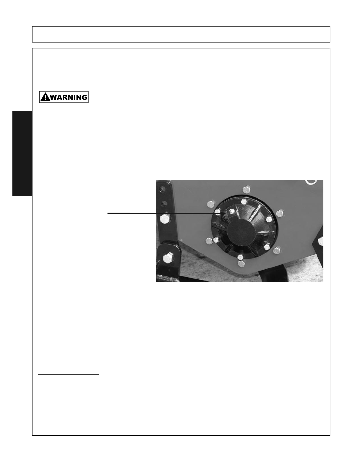
OUTBOARD BEARING
Grease the Outboard Bearing located
MAINTENANCE
on the right hand side of the tiller.
GREASE FITTING
Lubricate every 8 Hours
LUBRICATION
Before each use gearbox should be checked to be sure oil is at the proper levels. Operating the Machine with
the oil levels to low or to high can severly damage the machine. If it is determined that oil is needed follow these
steps.
NOTE: Make sure the Gearbox is level prior to removing the Inspection plug. Tilting forward may result
in over filling, tilting back may result in under filling. Use GL5-85W 140 or Triple Zero Grease which can
be poured and has an “EP” Extreme Pressure Additives in the Gearboxes.
TOP GEARBOX
1. Remove the vent plug on the top of the gearbox and the small inspection plug at the rear of the gearbox.
2. Pour the gear oil into the vent plug hole slowly until the oil starts to come out of the small hole at the rear.
DO NOT OVER FILL THE GEARBOX!
3. Replaces the small Inspection Plug and the Vent Plug. Clean up any excess gear oil.
RTG SERIES TILLER 05/16 MAINTENANCE 5-2
© Alamo Group.Inc.
Page 71
MAINTENANCE
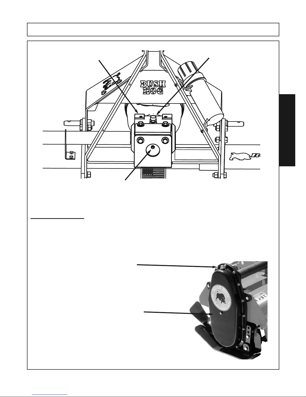
TOP GEARBOX
VENT PLUG LOCATION
Remove Vent Plug to
install gear oil. Re-install vent
plug when oil is at proper
level.
MAINTENANCE
SMALL INSPECTION PLUG
Remove and fill with gear oil until oil comes out this
hole and then place the plug back into the hole. DO
NOT fill past this point.
SIDE GEARBOX
1. Remove the vent plug on the top of the side gearbox and the small inspection plug at the
side of the gearbox.
2. Pour the gear oil into the vent plug hole slowly until the oil starts to come out of the small
hole on the side. DO NOT OVER FILL THE GEARBOX!
3. Replaces the small Inspection Plug and the Vent Plug. Clean up any excess gear oil.
VENT PLUG LOCATION
Remove Vent Plug to
install gear oil. Re-install vent
plug when oil is at proper
level.
SMALL INSPECTION PLUG
Remove and fill with gear oil
until oil comes out this hole
and then place the plug back
into the hole
DO NOT fill past this point.
.
RTG SERIES TILLER 05/16 Maintenance Section 5-3
© Alamo Group.Inc.
Page 72
MAINTENANCE
MAINTENANCE
RTG SERIES TILLER 05/16 Maintenance Section 5-4
© Alamo Group.Inc.
Page 73
MAINTENANCE
MAINTENANCE
RTG SERIES TILLER 05/16 Maintenance Section 5-5
© Alamo Group.Inc.
Page 74

MAINTENANCE
GENERAL MAINTENANCE
BLADES
Owner / Operator should routinely check the machine for broken and severly worn blades and replace
as necessary to keep the tiller in its best working condition.
FASTENERS
Check the tiller for loose pins, bolts or broken fasteners and tighten or replace as necessary. Refer
to Proper Bolt Tongue craft supplied in this manual for proper torque settings of fasteners.
SAFETY DEVICES
Make sure all Safety Shields and Guards are in place and in good working order.
Check to be sure all Safety Decals are in place and legible. Replace if needed.
STORAGE
MAINTENANCE
Your implement tiller represents an investment from which you should get the greatest possible benefit. Therefore, when the season is over, the tiller should be thoroughly checked and prepared for
storage so that a minimum amount of work will be required to put it back into operation for the next
season.
The following are suggested storage procedures:
1. Thoroughly clean the tiller.
2. Lubricate the tiller as covered in Maintenance Section.
3. Tighten all bolts and pins to the recommended torque.
4. Check the tiller for worn or damaged parts. Make replacements immediately.
5. Store the tiller in a clean, dry place.
6. Use spray touch-up enamel where necessary to prevent rust and maintain the appearance of the tiller.
7. Store unit away from human activity.
8. Do not park equipment where it can be exposed to direct contact to livestock.
Damage to machine or livestock could result.
9. Make sure to park the machine on a hard , level surface and engage safety devices.
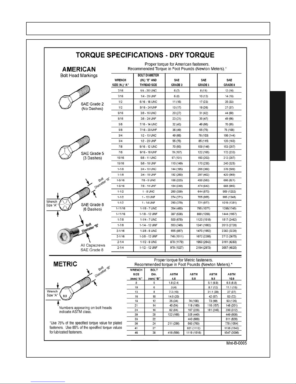
PROPER TORQUE FOR FASTENERS
The chart lists the correct tightening torque for fasteners. When bolts are to be tightened or replaced, refer
to this chart to determine the grade of bolts and the proper torque except when specific torque values are
assigned in manual text.
RECOMMENDED TORQUE IN FOOT POUNDS UNLESS OTHERWISE STATED IN THE MANUAL
NOTE: These values apply to fasteners as received from supplier, dry or when lubricated with normal engineoil. They do not apply if special graphited or molydisulphide greases or other extreme pressure lubricants areused. This applies to both UNF fine and UNC coarse threads.
RTG SERIES TILLER 05/16 Maintenance Section 5-6
© Alamo Group.Inc.
Page 75
MAINTENANCE
MAINTENANCE
RTG SERIES TILLER 05/16 Maintenance Section 5-7
© Alamo Group.Inc.
Page 76
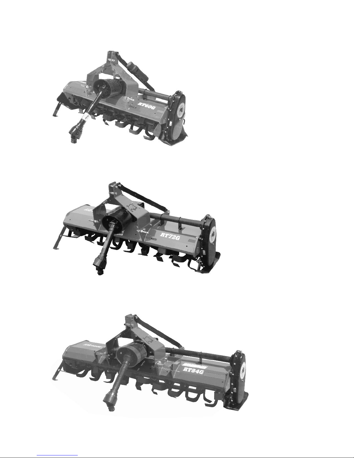
MODEL RT60G (SHOWN)
MODEL RT60GR (NOT SHOWN)
REVERSE ROTATION
MODEL RT72G (SHOWN)
MODEL RT72GR (NOT SHOWN)
REVERSE ROTATION
MODEL RT84G (SHOWN)
MODEL RT84GR (NOT SHOWN)
REVERSE ROTATION
Page 77
Page 78

Printed in U.S.A.
04-2016
RT60G, RT72G, RT84G
RT60GR, RT72GR, RT84GR
ROTARY TILLERS
P/N 50075234
 Loading...