

Page 1

This Operator's Manual is an integral part of the safe operation of this machine and must
be maintained with the unit at all times. READ,
UNDERSTAND, and FOLLOW the Safety
and Operation Instructions contained in this manual before operating the equipment. C01-
Cover
RMB 1660
REAR-MOUNT
BOOM MOWER
Published 10/10 Part No. 50068816C
OPERATOR’S MANUAL
BUSH HOG®
2501 Griffin Ave.
Selma, AL 36703
334-874-2700
www.bushhog.com
©2010 Alamo Group Inc.
$0.00
Page 2

To the Owner/Operator/Dealer
All implements with moving parts are potentially hazardous. There is no substitute for a cautious, safe-minded
operator who recognizes the potential hazards and follows reasonable safety practices. The manufacturer has
designed this implement to be used with all its safety equipment properly attached to minimize the chance of
accidents.
BEFORE YOU ST ART! Read the safety messages on the impl ement a nd shown in your ma nual. Obse rve th e rules
of safety and common sense!
WARRANTY INFORMATION:
Read and understand the complete Warranty Statement found in this Manual. Fill out the Warranty Registration
Form in full and return it to within 30 Days. Make certain the Serial Number of the Machine is recorded on the
Warranty Card and on the Warranty Form that you retain.
Page 3

In order to reduce accidents and enhance the safe operation of mowers, Bush Hog Division, in cooperation with
other industry manufacturers ha s developed the AEM/FEMA Industrial and Agricultural Mower Safety Practices
video and guide book.
The video will familiarize and instruct mower-tractor operators in safe practices when using industrial and
agricultural mowing equipment. It is important that Every Mower Operator
mowing equipment and be able to recognize the potential hazards that can occur while operating a mower. This
video, along with the mower operator’s manual and the warning messages on the mower, will significantly assist in
this important education.
Your Authorized Bush Hog Dealer may have shown this video and presented you a DVD Video when you
purchased your mower. If you or any mower operator have not seen this video, Watch the Video, Read this
Operator’s Manual, and Complete the Video Guidebook before operating your new mower. If you do not
understand any of the instructions included in the video or operator’s manual or if you have any questions
concerning safety of operation, contact your supervisor, dealer or Bush Hog.
If you would like a VHS video tape of th e video, pl ease mail AEM V ideo @alamo-gr oup.com or Fax AEM VHS V i deo
at (830) 372-9529 or mail in a completed copy of the form on the back of this page to AEM VHS Video 1502 E
Walnut Street, Seguin, TX 78155. and request the VHS video version. Please include your name, mailing address,
mower model and serial number.
Every operator should be trained for each piece of equipment (Tractor and Mower), understand the intended use,
and the potential hazards before operating the equipment.
The information and material listed above along with this Operator’s Manual can assist you in meeting the OSHA
requirement for annual operator training.
OSHA TRAINING REQUIREMENTS
be educated in the operation of their
The following training requirements have been taken from Title 29, Code of Federal Regulations Part 1928.57 (a)
(6). www.osha.gov
Operator instructions. At the time of initial assignment and at least annually thereafter the employer shall instruct
every employee who operates an ag ricultural t ractor and implements in the safe operating practices and servicing
of equipment with which they are or will be involved, and of any other practices dictated by the work environment.
Page 4

Alamo Group Ag. Division is willing to provide
one (1) AEM Mower Safety Practices Video
Please Send Me: VHS Format – AEM/FEMA Mower Operator Safety Video
DVD Format – AEM/FEMA Mower Operator Safety Video
Mower Operator’s Manual
AEM Mower Operator’s Safety Manual
Requester Name:_________________________________Phone: _____________________________
Requester Address:_____________________________________
City:___________________________________
State: __________________________________
Zip Code: ______________________________
Mower Model:__________________________Serial Number:___________________________
Date Purchased:_________________________Dealer Salesperson:_______________________
Dealership Name:_______________________ Dealership Location:______________________
Mail to:
AEM Video Services
1502 E. Walnut Street
Seguin, TX 78155
Or Fax to:
(830) 372-9529
Or E-mail to:
AEMVideo@alamo-group.com
Page 5

TABLE OF CONTENTS
SAFETY SECTION ..............................................................................................................1-1
General Safety Instructions and Practices .........................................................................................................1-2
Operator Safety Instructions and Practices .......................................................................................................1-3
Connecting & Disconnecting Implement Safety Instructions & Practices ..........................................................1-5
Equipment Operation Safety Instructions and Practices ....................................................................................1-6
Maintenance and Service Safety Instructions and Practices ..................................................... ... ... ... ... ..........1-12
Transporting Safety Instructions and Practices ............................................................................................... 1-14
Concluding Safety Instructions and Practices ..................................................................................................1-16
Decal Location .................................................................................................................................................1-17
Decal Description .............................................................................................................................................1-20
Federal Laws and Regulations ........................................................................................................................1-27
INTRODUCTION SECTION .................................................................................................2-1
ASSEMBLY SECTION ........................................................................................................3-1
TRACTOR SELECTION ....................................................................................................................................3-2
TRACTOR PREPARATION ...............................................................................................................................3-3
Fitting Operator Guard .......................................................................................................................................3-3
DEALER SETUP INSTRUCTIONS ....................................................................................................................3-4
ATTACHMENT TO TRACTOR .................................................... .... ... ... ... .... ... ... ...............................................3-5
Flail Head Attachment ............................ ... ....................................... ... ... ..........................................................3-12
OIL REQUIREMENTS .....................................................................................................................................3-13
Tank ...................................... .................................................................... .......................................................3-13
FITTING CONTROL UNIT IN CAB ..................................................................................................................3-13
Cable Controlled Models ..................................................................................................................................3-13
RUNNING UP PROCEDURE ...................................................... .... ... ....................................... ... ................... 3-14
REMOVAL FROM TRACTOR .........................................................................................................................3-14
STORAGE .......................................................................................................................................................3-15
SUBSEQUENT ATTACHMENT TO IDENTICAL TRACTOR ..........................................................................3-15
SUBSEQUENT ATTACHMENT TO DIFFERENT TRACTOR .........................................................................3-15
OPERATION SECTION .......................................................................................................4-1
Standard Equipment and Specifications ............................................................................................................4-3
OPERATOR REQUIREMENTS .........................................................................................................................4-4
TRACTOR REQUIREMENTS ............................................................................................................................4-5
ROPS and Seat Belt .................................................................... .... ... ...............................................................4-5
Operator Thrown Object Protection ...................................................................................................................4-5
Tractor Lighting and SMV Emblem .............. ......................................................................................................4-6
Tractor Ballast ....................................................................................................................................................4-6
Tractor Safety Devices .......................................................................................................................................4-7
Tractor Horsepower ...........................................................................................................................................4-7
3-Point Hitch ......................................................................................................................................................4-7
Hydraulics .......................................................................................................................................................... 4-7
Front End Weight ...............................................................................................................................................4-8
Power Take Off (PTO) .......................................................................................................................................4-8
GETTING ON AND OFF THE TRACTOR .........................................................................................................4-8
Boarding the Tractor ..........................................................................................................................................4-9
Dismounting the Tractor .....................................................................................................................................4-9
Page 6

STARTING THE TRACTOR ........................ ... .... ... ... ... ....................................... ... ... .......................................4-10
PRE-OPERATION INSPECTION AND SERVICE ...........................................................................................4-11
Tractor Pre-Operation Inspection/Service ........................................................................................................4-11
Boom Unit Pre-Operation Inspection and Service ...........................................................................................4-12
MACHINE CONTROLS ...................................................................................................................................4-19
Cable Controls - Identification & Function ........................................................................................................4-19
Lever Functions ...............................................................................................................................................4-20
Rotor Control ................................... ....................................... ... ... ....................................................................4-21
BREAKAWAY ..................................................................................................................................................4-22
ROTOR OPERATING SPEED .........................................................................................................................4-23
FORWARD SPEED .........................................................................................................................................4-23
HIGH VOLTAGE CABLES ........................... ... .... ... ....................................... ... ... .............................................4-23
Hedge Cutting Procedure ................................................................................................................................4-24
Working on Adverse Slopes .............................................................................................................................4-25
Lift Float Kit (Optional) .....................................................................................................................................4-25
DRIVING THE TRACTOR AND IMPLEMENT .................................................................................................4-26
Starting the Tractor ..........................................................................................................................................4-27
Brake and Differential Lock Setting ..................................................................................................................4-27
Driving the Tractor and Boom ...................... .................................................................... ................................4-28
OPERATING THE TRACTOR AND IMPLEMENT ...........................................................................................4-28
Foreign Debris Hazards ...................................................................................................................................4-29
Bystanders/Passersby Precautions .................... ... ... ... ... .... ... ... ....................................... ... .............................4-29
Engaging the Power Take Off (PTO) ..................... .................................................................... ......................4-30
Operating Speed and Ground Speed ..............................................................................................................4-31
Operating the Mower .......................................................................................................................................4-31
Operating the Attached Mower Heads ............................................................................................................. 4-33
Shutting Down the Attached Head ............................ ....................................... ................................................4-34
TRACTOR, BOOM, AND ATTACHED HEAD STORAGE ...............................................................................4-35
TRANSPORTING THE TRACTOR AND IMPLEMENT ...................................................................................4-35
Transport Position ............................................................................................................................................4-36
TRANSPORT POSITION-Head Attached .............. ....................................... ... ... .............................................4-37
TRANSPORT POSITION-Head Removal ................. .......................................................................................4-37
Transport Height ..............................................................................................................................................4-38
Transporting on Public Roadways ................................................................................................................... 4-38
Hauling the Tractor and Implement ..................................................................................................................4-41
TROUBLESHOOTING GUIDE .............................................. ... ... .... ...................................... .... ... ...................4-42
MAINTENANCE SECTION ..................................................................................................5-1
LUBRICATION ............................. ....................................... ...................................... .........................................5-2
General ..............................................................................................................................................................5-2
PTO SHAFT INSPECTION ................................................................................................................................5-2
PTO SHAFT LUBRICATION ..............................................................................................................................5-2
HYDRAULIC SYSTEM ......................................................................................................................................5-3
Oil Supply ...........................................................................................................................................................5-3
Filtration Maintenance ........................................................................................................................................5-3
HYDRAULIC HOSES .........................................................................................................................................5-3
Hose Replacement ............................................................................................................................................5-4
Hose Warranty ...................................................................................................................................................5-4
FLAILHEAD .......................................................................................................................................................5-5
CABLES ................................ ....................................... ....................................... ...............................................5-5
PTO GEARBOX .................................................................................................................................................5-6
STORAGE .........................................................................................................................................................5-6
PROPER TORQUE VALUES FOR FASTENERS .............................................................................................5-7
Page 7

SAFETY SECTION
© 2010 Alamo Group Inc.
Safety Section 1-1
Page 8
SAFETY
A careful operator is the best operator. Safety is of primary importance to the manufacturer and should be to
the owner/operator . Most accidents can be avoided by being aware of your equipment, your surroundings, and
observing certain precautions. The first section of this manual includes a list of Safety Messages that, if
followed, will help protect the operator and bystanders from injury or death. Read and understand these Safety
Messages before assembling, operating or servicing this Implement. This equipment should only be operated
by those persons who have read the manual, who are responsible and trained, and who know how to do so
responsibly.
The Safety Alert Symbol combined with a Signal Word, as seen below, is used throughout this
manual and on decals which are attached to the equipment. The Safety Alert Symbol means:
“ATTENTION! BECOME ALERT! YOUR SAFETY IS INVOLVED!” The Symbol and Signal Word
are intended to warn the owner/operator of impending hazards and the degree of possible injury
faced when operating this equipment.
Indicates an imminently hazardous situation that, if not avoided, WILL result in DEATH OR
VERY SERIOUS INJURY.
Indicates an imminently hazardous situation that, if not avoided, COULD result in DEATH
OR SERIOUS INJURY.
Indicates an imminently hazardous situation that, if not avoided, MAY result in MINOR
INJURY.
Identifies special instructions or procedures that, if not strictly observed, could result in
damage to, or destruction of the machine, attachments or the environment.
NOTE: Identifies points of particular interest for more efficient and convenient operation or repair.
(SG-1)
Practice all usual and customary safe working precautions and above all---remember safety is
up to YOU
. Only YOU can prevent serious injury or death from unsafe practices.
READ, UNDERSTAND, and FOLLOW the following Safety Messages. Serious injury or
death may occur unless care is taken to follow the warnings and instructions stated in the
Safety Messages. Always use good common sense to avoid hazards.
(SG-2)
Si no lee ingles, pida ayuda a alguien que si lo lea para que le traduzca las
medidas de seguridad.
(SG-3)
General Safety Instructions and Practices
SAFETY
RMB 1660 11/10 Safety Section 1-2
© 2010 Alamo Group Inc.
Page 9
SAFETY
Engine Exhaust, some of its constituents, and certain vehicle components contain or emit
chemicals known to the state of California to cause cancer and birth defects or other
reproductive harm.
(SG-30)
Battery posts, terminals and related accessories contain lead and lead compounds,
chemicals known to the state of California to cause cancer, birth defects or other
reproductive harm.
(SG-31)
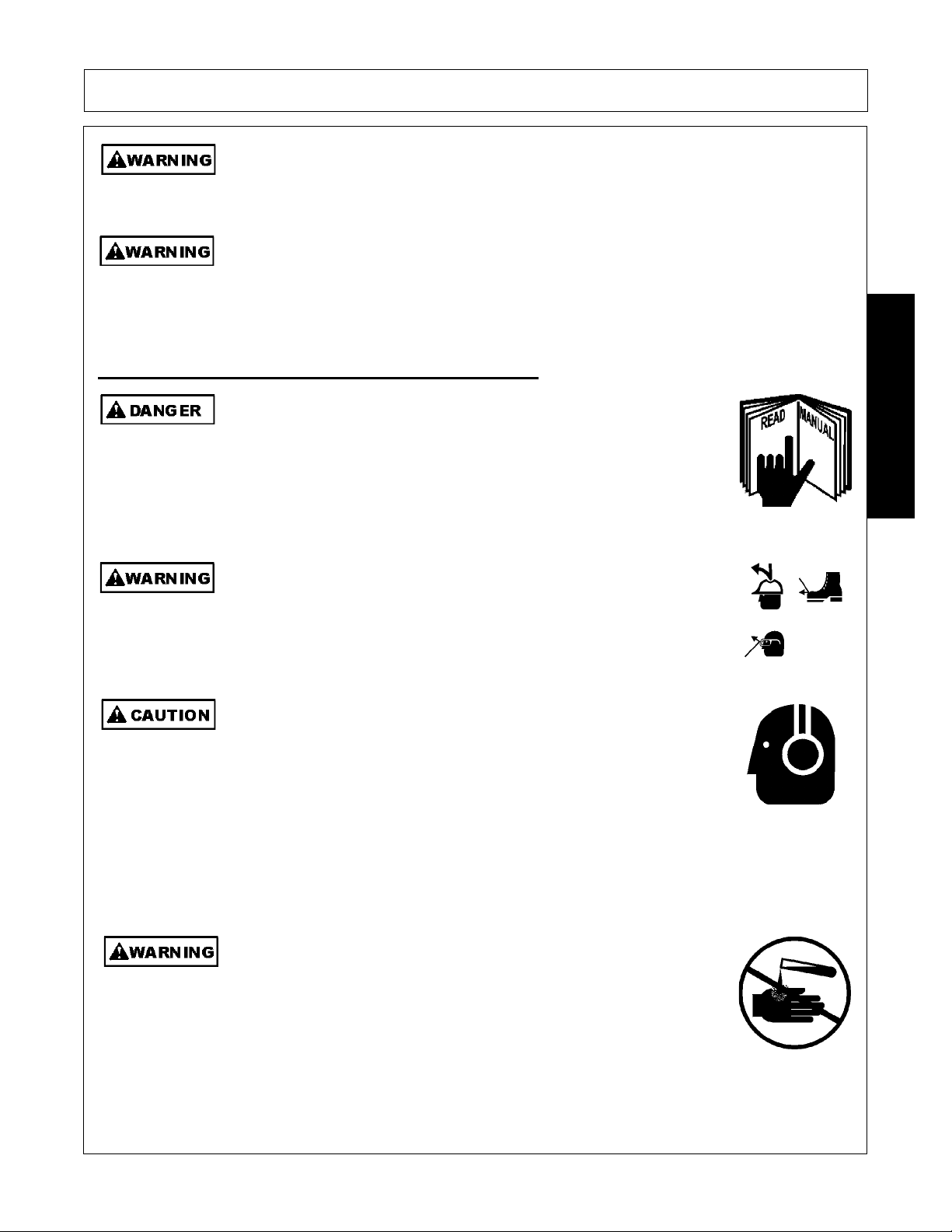
Never operate the Tractor or Implement until you have read and
completely understand this Manual, the Tractor Operator’s Manual, and
each of the Safety Messages found in the Manual or on the Tractor and
Implement. Learn how to stop the tractor engine suddenly in an
emergency. Never allow inexperienced or untrained personnel to
operate the Tractor or Implement without supervision. Make sure the
operator has fully read and understood the manuals prior to operation.
(SG-4)
The operator and all support personnel should wear hard hats, safety
shoes, safety glasses, and proper hearing protection at all times for
protection from injury including injury from items that may be thrown by
the equipment.
(SG-16)
PROLONGED EXPOSURE TO LOUD NOISE MAY CAUSE
PERMANENT HEARING LOSS! Tractors with or without an Implement
attached can often be noisy enough to cause permanent hearing loss.
We recommend that you always wear hearing protection if the noise in
the Operator’s position exceeds 80db. Noise over 85db over an
extended period of time will cause severe hearing loss. Noise over 90db
adjacent to the Operator over an extended period of time will cause
permanent or total hearing loss. NOTE: Hearing loss from loud noise
[from tractors, chain saws, radios, and other such sources close to the
ear] is cumulative over a lifetime without hope of natural recovery.
(SG-I7)
Always read carefully and comply fully with the manufacturer’s
instructions when handling oil, solvents, cleansers, and any other
chemical agent.
(SG-22)
Operator Safety Instructions and Practices
SAFETY
RMB 1660 11/10 Safety Section 1-3
© 2010 Alamo Group Inc.
Page 10

SAFETY
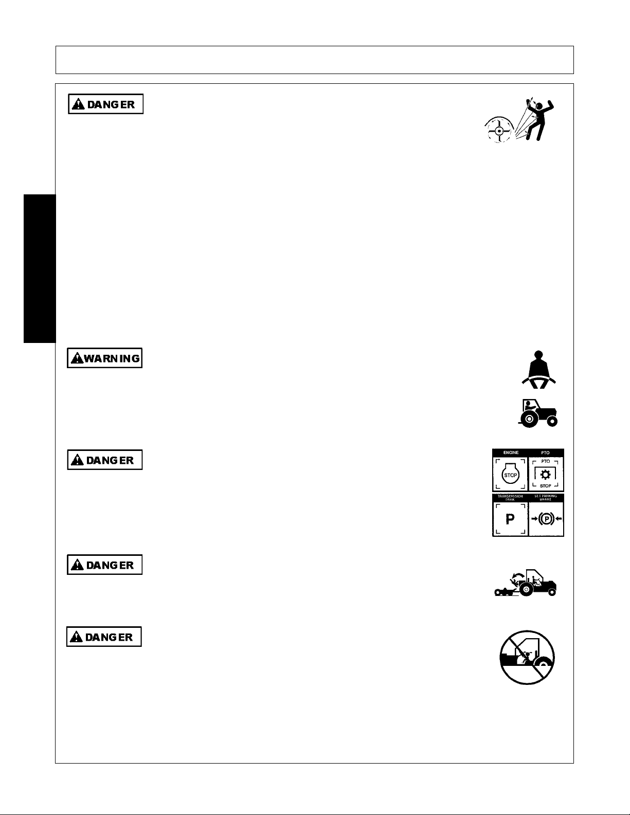
KEEP AWAY FROM ROTATING ELEMENTS to prevent entanglement
and possible serious injury or death.
(SG-24)
Never allow children to play on or around Tractor or Implement. Children can slip or fall off
the Equipment and be injured or killed. Children can cause the Implement to shift or fall
crushing themselves or others.
(SG-25)
NEVER use drugs or alcohol immediately before or while operating the
Tractor and Implement. Drugs and alcohol will affect an operator’s
alertness and coordination and therefore affect the operator’s ability to
operate the equipment safely. Before operating the Tractor or Implement,
an operator on prescription or over-the-counter medication must consult
a medical professional regard ing any side effects of the medication that
would hinder their ability to operate the Equipment safely. NEVER
knowingly allow anyone to operate this equipment when their alertne ss or
coordination is impaired. Serious injury or death to the operator or others
could result if the operator is under the influen ce of drugs or a lcohol.
(SG-27)
Prolonged operation may cause operator boredom and fatigue affecting safe operation.
Take scheduled work breaks to help prevent these potentially impaired operating
conditions. Never operate the Implement and Tractor in a fatigued or bored mental state
which impairs proper and safe operation.
(SG-32)
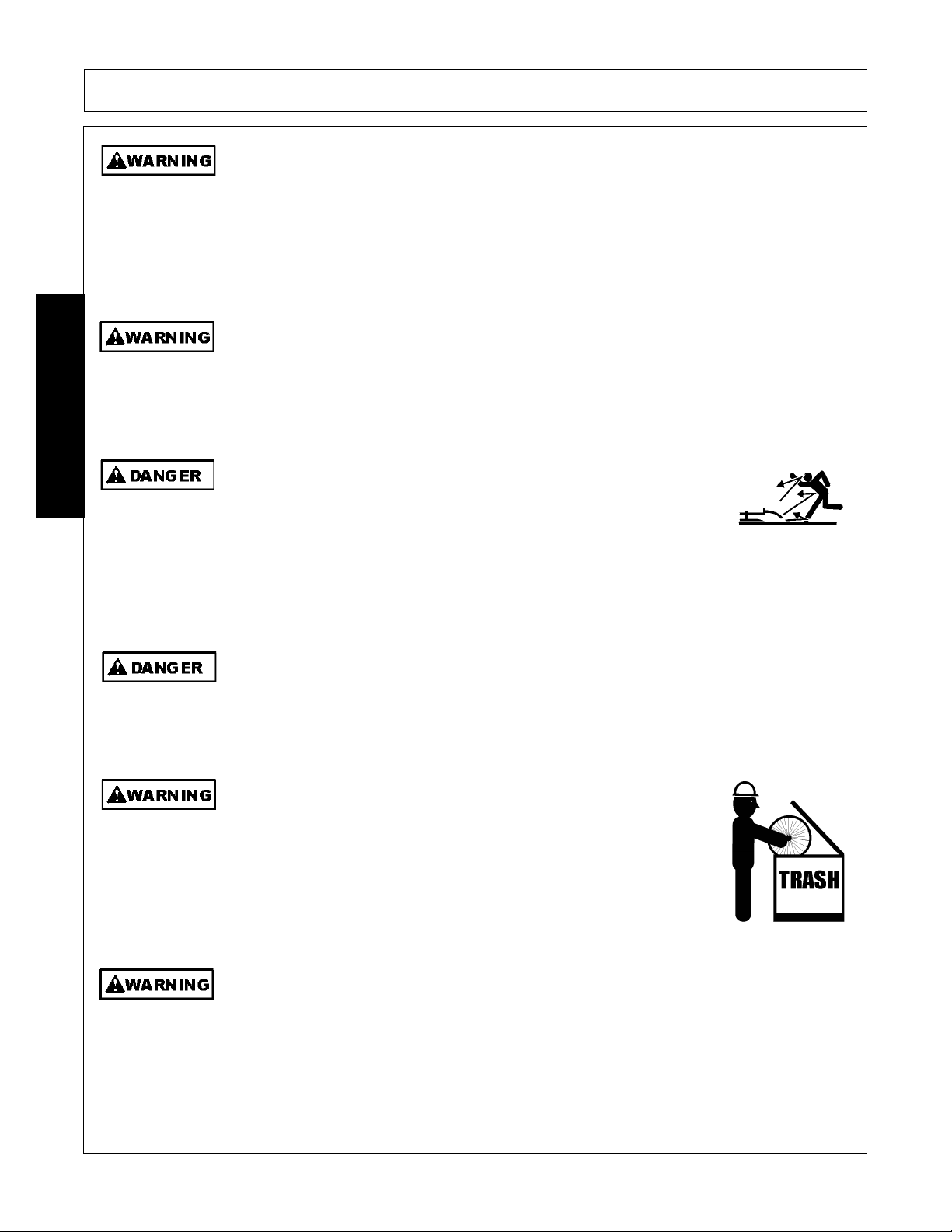
Use extreme caution when getting onto the Implement to perform repairs, maintenan ce and
when removing accumulated material. Only stand on solid flat surfaces to ensure good
footing. Use a ladder or raised stand to access high spots which cannot be reached from
ground level. Slipping and falling can cause serious injury or death.
(SG-33)
Avoid contact with hot surfaces including hydraulic oil tanks, pumps, motors, valves and
hose connections. Relieve hydraulic pressure before performing maintenance or repairs.
Use gloves and eye protection when servicing hot components. Contact with a hot surface
or fluid can cause serious injury from burns or scalding.
(SG-34)
DO NOT operate this Implement on a Tractor that is not properly maintained. Should a
mechanical or Tractor control failure occur while operating, immediately shut down the
Tractor and perform repairs before resuming operation. Serious injury and possible death
could occur from not maintaining this Implement and Tractor in good operating condition.
(SG-36)
Avoid contact with hot surfaces of the engine or muffler. Use gloves and eye protection
when servicing hot components. Contact with a hot surface or fluid can cause serious injury
from burns or scalding.
(SG-38)
SAFETY
RMB 1660 11/10 Safety Section 1-4
© 2010 Alamo Group Inc.
Page 11
SAFETY
The rotating parts of this machine continue to rotate even after the Tractor has been turned
off. The operator shoul d remain in his seat for 60 se conds af ter the b rake has been set, the
PTO disengaged, the tractor turned off, and all evidence of rotation has ceased.
(SBM-5)
“Wait a minute...Save a life!”
Do not put hands or feet under mower decks. Blade Contact can result
in serious injury or even death. Stay away until all motion has stopped
and the decks are securely blocked up.
(SFL-2)
Do not put hands or feet under mower decks. Blade Contact can result
in serious injury or even death. Stay away until all motion has stopped
and the decks are securely blocked up.
(SGM-09)
Do not put hands or feet near the cutter bar. Blade contact can result
in serious injury. Stay away until all motion has stopped and the
mower is securely blocked up.
(SSM-1)
Do not operate the implement while wearing loose fitting clothing. Entanglement of the
clothing with the rotating elements can result in serious injury or even death. Stay clear of
all rotating elements at all times.
(SSP-03)
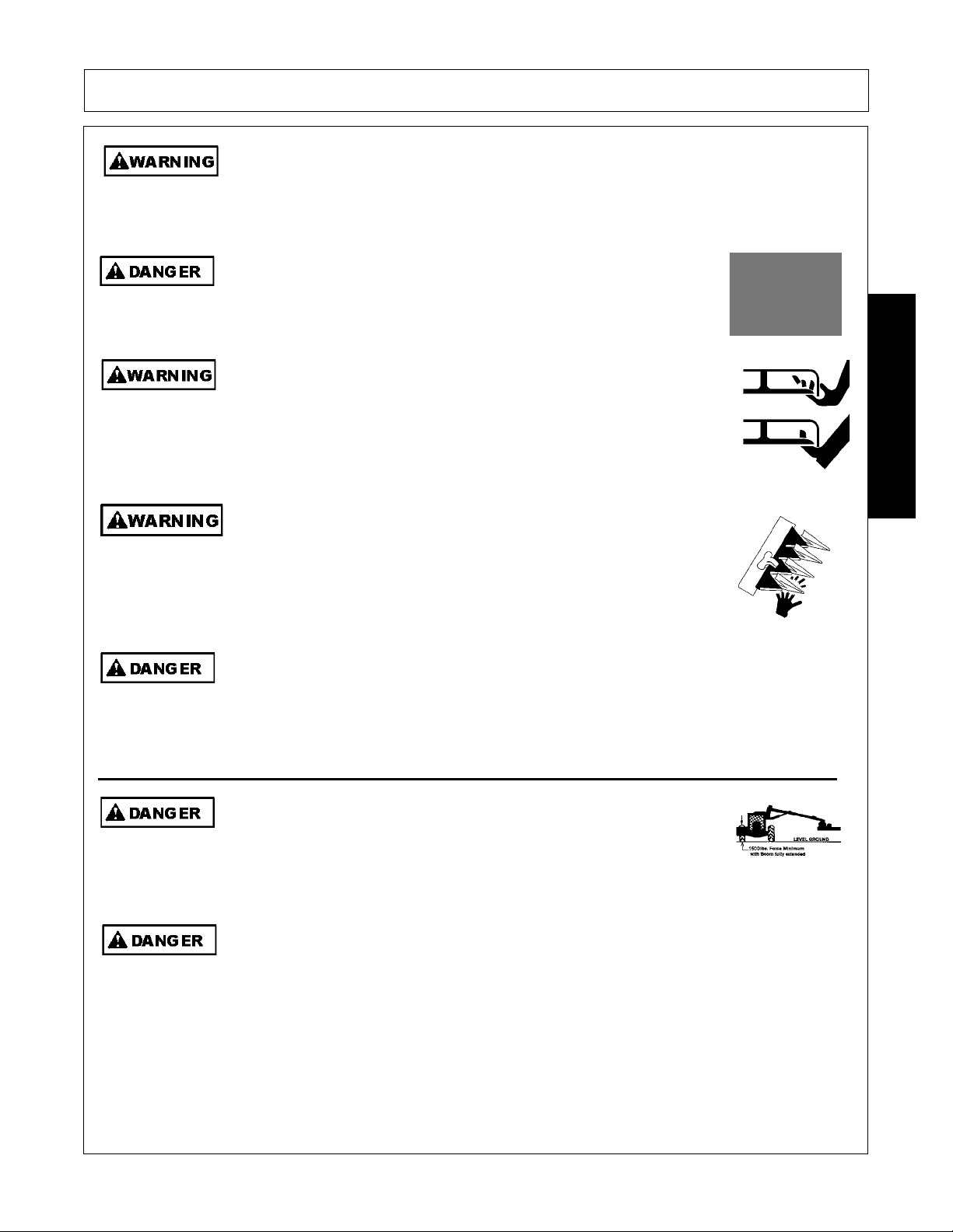
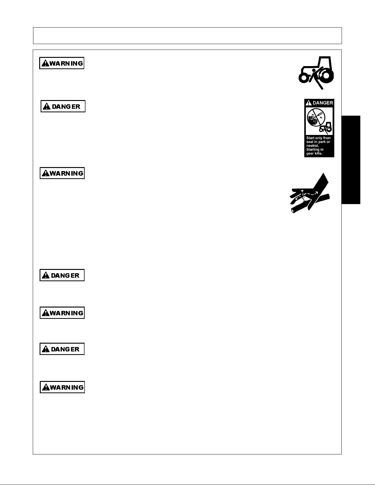
Each Rear Wheel must have a minimum of 1500 pound conta ct with the
surface to prevent lateral instability and possible tip-over which could
result in serious bodily injury or even death. Widen the wheel tread and
add weights if needed. Refer to the mounting instructions or call Customer Service if you
need assistance with Counterweight Procedure.
(SBM-11)
Do Not attempt to raise or lower the boom or mower head unless the Implement is secure ly
attached to the Tractor. The Implement could tip over and cause equipment damage and
possible serious injury or death. Do Not use the boom controls to assist in installing the
implement on the tractor. Raise or Lower the boom and mower head only while seated in
the Tractor operator’s seat with the seat belt securely fastened. Inadvertent contact with
the boom controls could allow a component to fall. A sudden or inadvertent fall by any of
these components could cause serious injury or even death.
(SBM-23)
SAFETY
Connecting & Disconnecting Implement Safety Instructions & Practices
RMB 1660 11/10 Safety Section 1-5
© 2010 Alamo Group Inc.
Page 12
SAFETY
Never leave the Tractor and Implement unattended while the Implement is in the lifted
position. Accidental operation of lifting lever or a hydraulic failure may cause sudden drop
of unit with injury or death by crushing. To properly park the implement when disconnecting
it from the tractor , lower the st and and put the retaining pin securely in place, or pu t a secure
support under the A-Frame. Lower the implement carefully to the ground. Do not put hands
or feet under lifted components .
(S3PT-1)
This Implement may be wider than the Tractor. Be careful when operating or transporting
this equipment to prevent the Implement from running into or striking sign posts, guard rails,
concrete abutments or other solid objects. Such an impact could cause the Implement and
Tractor to pivot violently resulting in loss of steering control, serious injury, or even death.
Never allow the Implement to contact obstacles.
(S3PT-12)
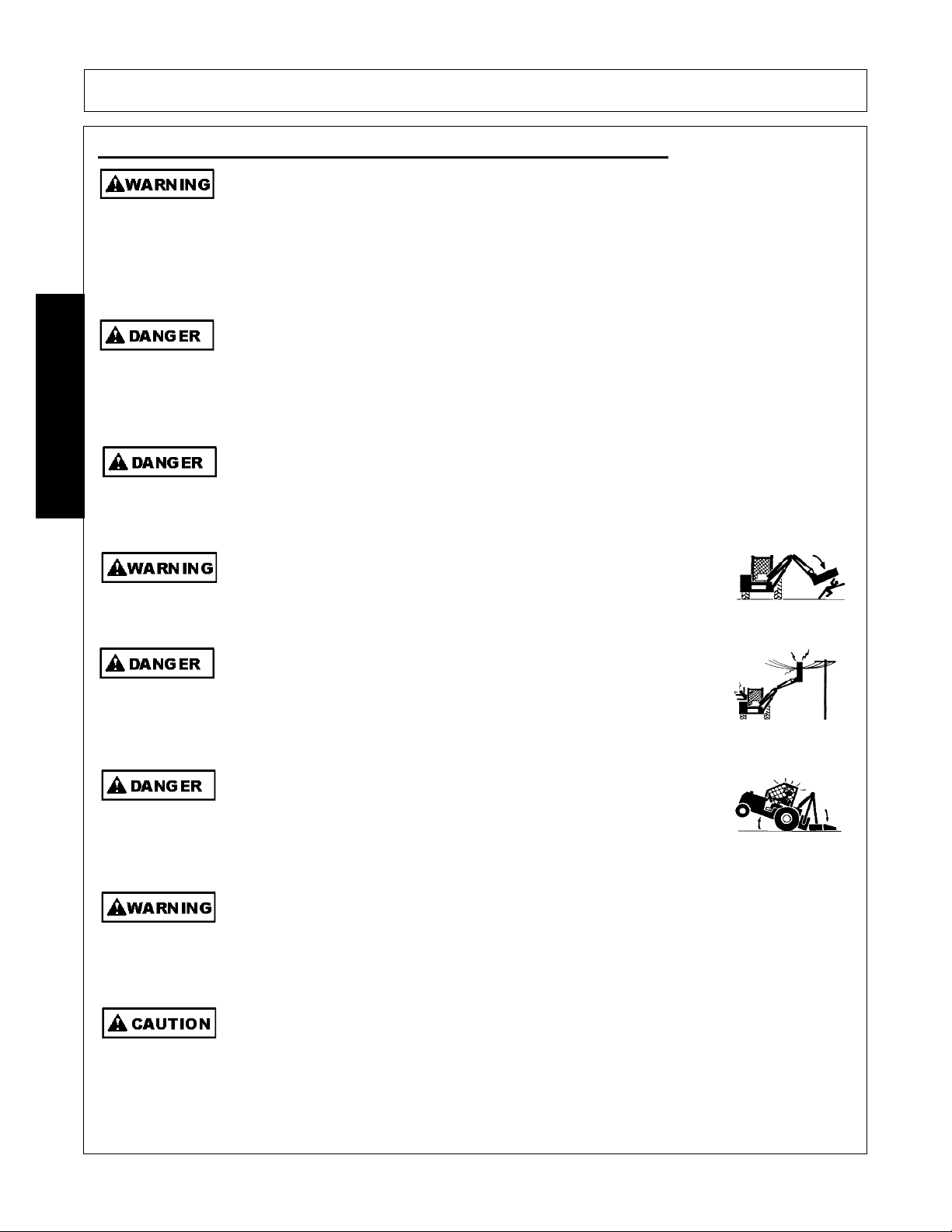
Use extreme caution when raising the Mower head. Stop the Blades from turning when the
Mower Head is raised and passersby are within 300 feet. Raising the Mower head
exposes the Cutting Blades which creates a potentially serious hazard and can cause
serious injury by objects thrown from the Blades or by contact with the Blades.
(SBM-2)
Never Leave the mower unattended while the head is in the raised
position. The mower could fall causing serious injury to anyone who
might inadvertently be under the mower
(SBM-4)
Always keep a careful lookout and use extreme care when working
around overhead obstructions. Never allow the Mower head or boom
within 10 feet of any power line. When working close to overhead
power lines consult your electric company for a safe code of operation.
(SBM-7)
The center of Gravity of Tractors equipped with a Rear-Mounted Boom
Mower is shifted to the rear and removes weight from the front wheels.
Add front ballast until at least 20% of the tractors weight is on the front
wheels to prevent rearing up, loss of steering control, and possibly
injury.
(SBM-10)
Use extreme care and Safety A wareness when using the boom mower head to mulch loose
brush or wood that has fallen on the ground from overhead trimming. DO NOT mulch this
debris if bystanders, vehicles, livestock or buildings are within 300 feet of the mower. This
cut debris can be thrown at great velocities and could result in serious injury or even death.
(SBM-17)
Do not back up this implement when the boom or mower head is extended. Backing could
damage the machine or its components.
(SBM-19)
Equipment Operation Safety Instructions and Practices
SAFETY
RMB 1660 11/10 Safety Section 1-6
© 2010 Alamo Group Inc.
Page 13

SAFETY
Follow these guidelines to reduce the risk of equipment and
grass fires while operating, servicing, and repairing the Mower
and Tractor:
-Equip the Tractor with a fire extinguisher in an accessible
location.
-Do Not operate the Mower on a Tractor with an underframe
exhaust.
-Do Not smoke or have an open flame near the Mower and
Tractor.
-Do Not drive into burning debris or freshly burnt areas.
-Do Not attempt to mow or place the mower head close to
burning debris.
-Never allow clippings or debris to collect near drivelines,
gearboxes or hydraulic components such as valves, tanks,
pumps and motors. Periodically shut down the Tractor and
Mower and clean clippings and collected debris from the
mower deck.
(SBM-20)
Do not operate Mower if excessive vibration exists. Shut down PTO and the Tractor
engine. Inspect the Mower to determine th e source of the vibration. If Mower blades are
missing or damaged replace them immediately. Do not operate the mower until the
blades have been replaced and the Mower operates smoothly. Operating the Mower with
excessive vibration can result in component failure and broken objects to be thrown
outward at very high velocities. To reduce the possibility of property damage, serious injury,
or even death, never allow the Mower to be operated with blades missing.
(SFL-4)
SAFETY
RMB 1660 11/10 Safety Section 1-7
© 2010 Alamo Group Inc.
Page 14
SAFETY
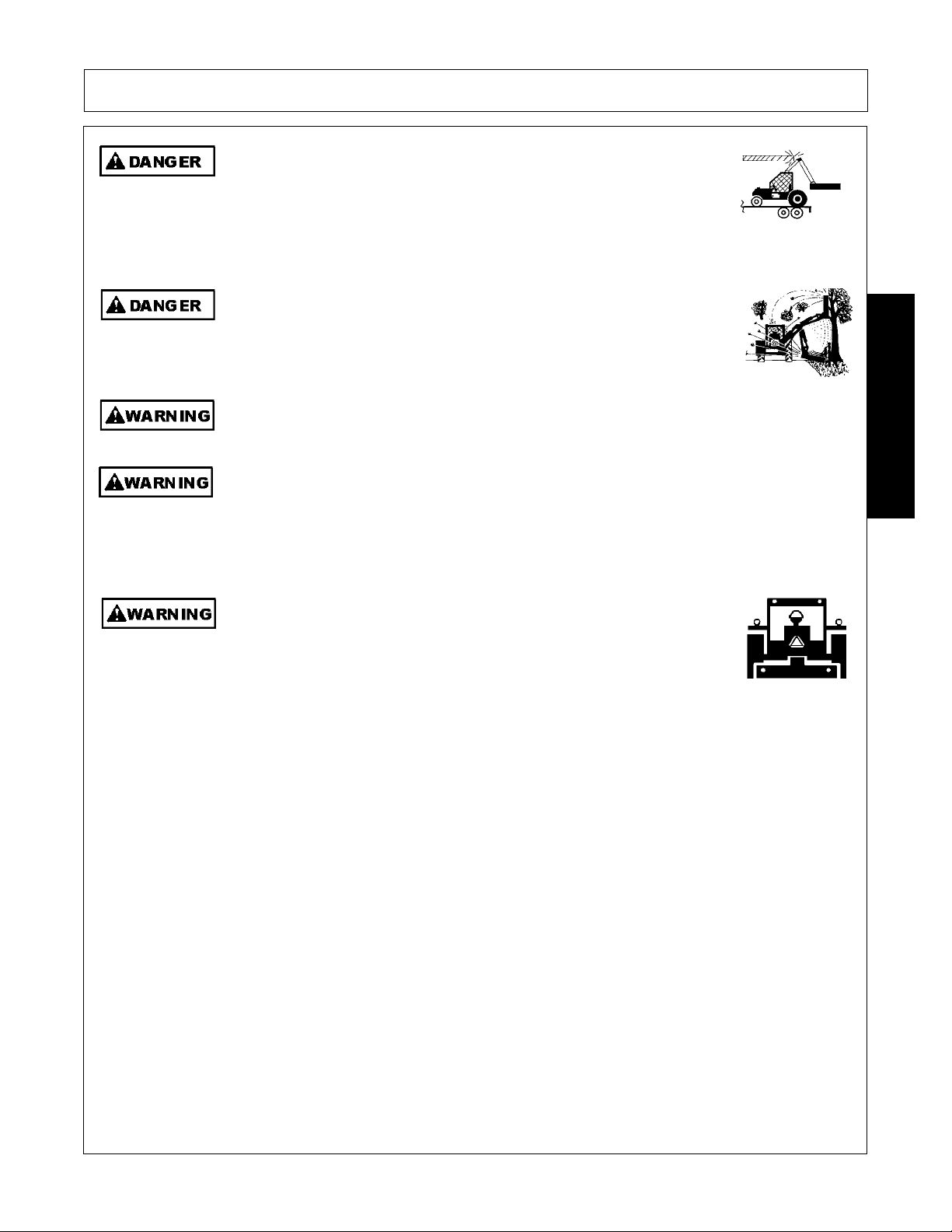
Flail Mowers are capable under adverse conditions of throwing
objects for great distances (300 feet or more) and causing serious
injury or death. Follow safety messages carefully.
STOP MOWING IF PASSERSBY ARE WITHIN 300 FEET UNLESS:
-Front and Rear Deflectors, Chain Guards, or Bands are installed and in good, workable
condition;
-Mower sections or Wings are running close to and parallel to the ground without
exposed Blades;
-All areas have been thoroughly inspected and all foreign material such as rocks, cans,
glass, and general debris has been removed.
NOTE: Where there are grass and weeds high enough to hide debris that could be
struck by the blades, the area should be: inspected and large debris r emo ved, mowed at
an intermediate height, inspecte d closely with an y rema ining de bris being remo ved, and
mowed again at desired final height. (This will also reduce power required to mow,
reduce wear and tear on the Mower drivetrain, spread cut material better, eliminate
streaking, and make the final cut more uniform.)
(SFL-6)
Operate this Equipment only with a Cab Tractor. Always wear seat belts. (SG-45)
BEFORE leaving the tractor seat lower the implement, set the parking
brake and/or set the tractor transmission in parking gear, disengage the
PTO, stop the engine, remove the key, and wait for all moving parts to
stop. Place the tractor shift lever into a low range or parking gear to
prevent the tractor from rolling. Never dismount a Tractor that is moving
or while the engine is running. Operate the Tractor controls from the
tractor seat only.
(SG-9)
Never allow children or other persons to ride on the Tracto r or Implement.
Falling off can result in serious injury or death.
(SG-10)
Never allow children to operate, ride on, or come close to the Tractor or
Implement. Usually, 16-17 year-old children who are mature and
responsible can operate the implement with adult supervision, if they
have read and understand the Operator’s Manuals, been trained in
proper operation of the tractor and Implement, and are physically large
enough to reach and operate the controls easily.
(SG-11)
SAFETY
RMB 1660 11/10 Safety Section 1-8
© 2010 Alamo Group Inc.
Page 15
SAFETY
Do not mount or dismount the Tractor while the tractor is moving. Mount
the Tractor only when the Tractor and all moving parts are completely
stopped.
(SG-12)
Start tractor only when properly seated in the Tractor seat. Starting a
tractor in gear can result in injury or death. Read the Tractor operators
manual for proper starting instructions.
(SG-13)
Do not operate this Equipment with hydraulic oil or fuel leaking. Oil
and fuel are explosive and their presence could present a hazard. Do
not check for leaks with your hand! High-pressure oil streams from
breaks in the line could penetrate the skin and cause tissue damage
including gangrene. To check for a hose leak, SHUT the unit ENGINE
OFF and remove all hydraulic pressure. Wear oil imp ene trab le glo ves ,
safety glasses and use Cardboard to check for evidence of oil leaks. If
you suspect a leak, REMOVE the HOSE and have it tested at a Dealer.
If oil does penetrate the skin, have the injury treated immediately by a
physician knowledgeable and skilled in this procedure.
(SG-15)
Never run the Tractor engine in a closed building or without adequate ventilation. The
exhaust fumes can be hazardous to your health.
(SG-23)
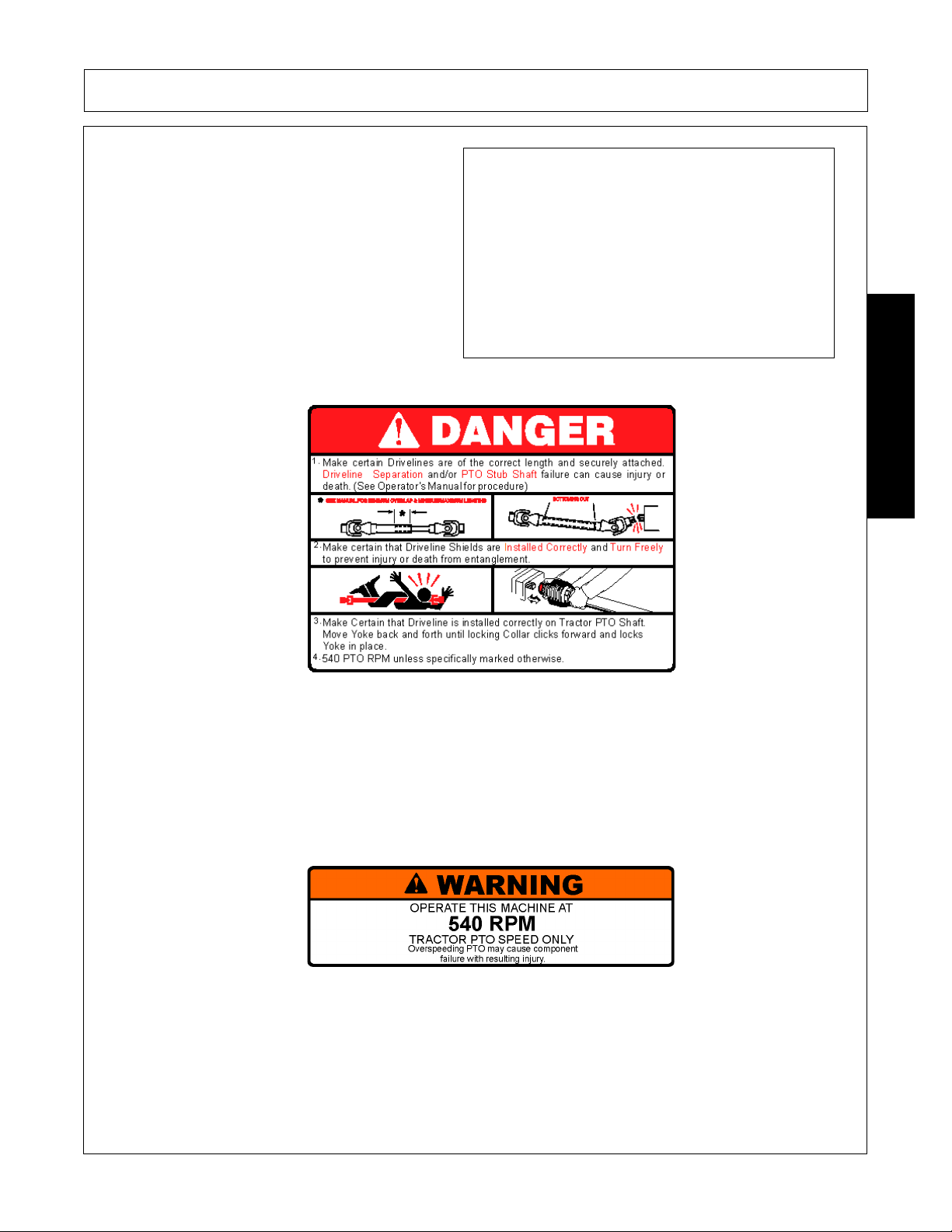
Do not exceed the rated PTO speed for the Implement. Excessive PTO speeds can cause
Implement driveline or blade failures resulting in serious injury or death.
(SG-26)
Operate the Tractor and/or Implement control s only while properly seated in the Tractor seat
with the seat belt securely fastened around you. Inadvertent movement of the Tractor or
Implement may cause serious injury or death.
(SG-29)
In case of mechanical difficulty during operation, place the transmission in the park
position, set the parking brake, shut down all power, including the PTO and the engine and
remove the key. Wait until all rotating motion has stopped before dismounting.
(SG-39)
SAFETY
RMB 1660 11/10 Safety Section 1-9
© 2010 Alamo Group Inc.
Page 16
SAFETY
Do Not operate this equipment in areas where insects such as bees may attack you and/or
cause you to lose control of th e equipment. If you must enter in such areas, use a tractor
with an enclosed Cab and close the windows to prevent insects from entering. If a tractor
cab is not available, wear suitable clothing including head, face, and hand protection to
shield you from the insects. Attacking insects can cause you to lose control of the tractor,
which can result in serious injury or death to you o r bystanders. Never dismount a moving
tractor.
(SG-40)
Mow only in conditions where you have clear visibility in daylight or with adequate artificial
lighting. Never mow in darkness or foggy conditions where you cannot clearly see at least
300 feet (90 m) in front and to the sides of the tractor and mower. Make sure that you can
clearly see and identify passersby, steep slopes, ditches, drop-offs, overhead obstructions,
power lines, debris and foreign objec ts. If you are unab le to clear ly see thes e type of ite ms
discontinue mowing.
(SGM-1)
There are obvious and hidden potential hazards in the operation of this
Mower. REMEMBER! This machine is often operated in heavy brush
and in heavy weeds. The Blades of this Mower can throw objects if
shields are not properly installed and maintained. Serious injury or even
death may occur unless care is taken to insure the safety of the operator,
bystanders, or passersby in the area. Do not operate this machine with
anyone in the immediate area. Stop mowing if anyone is within 300 feet
of mower.
(SGM-02)
The rotating parts of this machine have been designed and tested for rugged use.
However, the blades could fail upon impact with heavy, solid objects such as metal guard
rails and concrete structures. Such impact could cause the broken objects to be thrown
outward at very high velocities. To reduce the possibility of property damage, serious
injury, or even death, never allow the cutting blades to contact such obstacles.
(SGM-4)
Extreme care should be taken when operating near loose objects such
as gravel, rocks, wire, and other debris. Inspect the area before
mowing. Foreign objects should be removed from the site to prevent
machine damage and/or bodily injury or even death. Any objects that
cannot be removed must be clearly mark ed and car efully avo ide d b y th e
operator. Stop mowing immediately if blades strike a foreign object.
Repair all damage and make certain rotor or blade carrier is balanced
before resuming mowing.
(SGM-05)
Many varied objects, such as wire, cable, rope, or chains, can become entangled in the
operating parts of the mower head. These items could then swing outside the housing at
greater velocities than the blades. Such a situation is extremely hazardous and could result
in serious injury or even death. Inspect the cutting area for such objects before mowing.
Remove any like object from the site. Never allow the cutting blades to contact such items.
(SGM-06)
SAFETY
RMB 1660 11/10 Safety Section 1-10
© 2010 Alamo Group Inc.
Page 17
SAFETY
Mow at the speed that you can safely operate and control the tractor and mower. The
correct mowing speed depends on terrain condition and grass type, density, and height of
cut. Normal ground speed range is from 2 to 5 mph(3-8 kph). Use slow mowing speeds
when operating on or near steep slopes, ditches, drop-offs, overhead obstructions, power
lines, or when debris and foreign objects are to be avoided.
(SGM-07)
Avoid mowing in reverse direction when possible. Check to make sure there are no
persons behind the mower and use extreme care when mowing in reverse. Mow only at a
slow ground speed where you can safely operate and control the tractor and mower.
Never mow an area that you have not inspected and removed debris or foreign material.
(SGM-08)
Do not mow with two machines in the same area except with Cab tractors with the windows
closed.
(SGM-11)
Follow these guidelines to reduce the risk of equipment and grass fires
while operating, servicing, and repairing the Mower and Tractor:
-Equip the Tractor with a fire extinguisher in an accesible location.
-Do Not operate the Mower on a Tractor with an underframe exhaust.
-Do Not smoke or have an open flame near the Mower and Tractor.
-Do Not drive into burning debris or freshly burnt area s.
-Ensure slip clutches are properly adjusted to prevent excessive slippage and plate heating.
-Never allow clippings or debris to collect near drivelines, slip clutches, and gearboxes.
Periodically shut down the T ractor an d Mo we r and cl ean clip pin gs and collected deb ris from
the mower deck.
(SGM-12)
The Mower is designed for certain mowing applications and is rated to cut up to a specific
size vegetation (see Mower Standard Equipment and Specifications). DO NOT use this
mower to cut vegetation above the Mower’s rated capacity or to cut any type of nonvegetative material. Only operate this Mower on a properly sized and equipped Tractor.
Operating this Mower in an application for which it is not designed and/or operating the
Mower with the wrong size Tractor can cause Mower component damage and equipment
failure resulting in possible serious injury or death.
(SGM-14)
Never leave the Implement and Power Unit unattended while the Implement is in the raised
position. Accidental operation of a lifting lever or a hydraulic failure may cause the
implement to suddenly fall causing serious injury or possible death to anyone who might
inadvertently be under the Implement. Lower the implement carefully to the gr ound. Do not
put hands or feet under lifted componen ts.
(SPU-3)
SAFETY
RMB 1660 11/10 Safety Section 1-11
© 2010 Alamo Group Inc.
Page 18
SAFETY
Do not let the Blades turn when the Mower Deck is raised for any
reason, including clearance or for turning. Raising the Mower deck
exposes the Cutting Blades which creates a potentially serious hazard
and could cause serious injury or even death from objects thrown from
the Blades.
(SRM-07)
Make sure the PTO shield, integral driveline shields, and input shields
are installed when using PTO-driven equipment. Always replace any
shield if it is damaged or missing.
(S3PT-8)
Always disconnect the main PTO Driveline from the Tractor before performing service on
the Implement. Never work on the Implement with the tractor PT O dr iveline conn ected and
running. Rotating Parts, Blades or Drivelines could turn without warning and cause
immediate entanglement, injury or death.
(S3PT-11)
Never interfere with factory-set hydraulic calibrations. Any change in calibration could
cause a failure of the equipment and may result in injury.
(SBH-13)
Relieve hydraulic pressure prior to doing any maintenance or repair work on the Implement.
Place the Mower Head on the ground or securely supported on blocks or stands, disengage
the PTO, and turn off the engine. Push and pull the control Levers or Joystick several times
to relieve pressure prior to starting any maintenance or repair work.
(SBM-6)
All Safety Shields, Guards and Safety devices including (but not
limited to) - the Deflectors, Chain Guards, Steel Guards,
Gearbox Shields, PTO integral shields , and Retractable Door
Shields should be used and maintained in good working condition. All safety
devices should be inspected carefully at least daily for missing or broken
components. Missing, broken, or worn items must be replaced at once to reduce
the possibility of injury or death from thrown objects, entanglement, or blade
contact.
(SBM-18)
DO NOT allow any person under a raised boom or mower head unless
it is securely locked up or supported. DO NOT approach the
Implement unless the Tractor is turned off and all motion has ceased.
Never work under the frame work, or any lifted component unless the implement is
securely supported or blocked up. Inadvertent contact with the controls could allow a
component to fall. A sudden or inadvertent fall by any of these components could cause
serious injury or even death.
(SBM-22)
Maintenance and Service Safety Instructions and Practices
SAFETY
RMB 1660 11/10 Safety Section 1-12
© 2010 Alamo Group Inc.
Page 19
SAFETY
Always maintain the safety signs in good readable condition. If th e safety signs are missing,
damaged, or unreadable, obtain and install replacement safety signs immediately.
(SG-5)
Do not modify or alter this Implement. Do not permit anyone to modify or alter this
Implement, any of its components or any Implement function.
(SG-8)
Never work under the Implement, the framework, or any lifted
component unless the Implement is securely supported or blocked up
to prevent sudden or inadvertent falling which could cause serious
injury or even death.
(SG-14)
Never attempt to lubricate, adjust, or remove material from the Implement while it is in
motion or while tractor engine is running.
(SG-20)
Periodically inspect all moving parts for wear and replace when
necessary with authorized service parts. Look for loose fasteners, worn
or broken parts, and leaky or loose fittings. Make sure all pins have
cotter pins and washers. Serious injury may occur from not maintaining
this machine in good working order.
(SG-21)
Do Not fill fuel tank while engine is running. Refuel only after engine has cooled down. If
fuel is spilled, move machine away from the area of the spill and avoid creating any source
of ignition until the gasoline has evaporated.
(SG-28)
Perform service, repairs and lubrication according to the maintenance section. Ensure the
unit is properly lubricated as specified in the lubrication schedule and all bolts and nuts are
properly torqued. Failure to properly servic e, repair and maintain this Implement in good
operating condition could cause component failure and possible serious injury or even
death.
(SG-35)
Use caution and wear protective gloves when handling sharp objects such as blades,
knives, and other cutting edges. Be alert to worn component surfaces which have sharp
edges. Sharp surfaces can inflict severe laceration injuries if proper hand protection is not
worn.
(SG-37)
SAFETY
RMB 1660 11/10 Safety Section 1-13
© 2010 Alamo Group Inc.
Page 20
SAFETY
Replace bent or broken blades with new blades. NEVER ATTEMPT TO STRAIGHTEN,
WELD, OR WELD HARDFACING ON BLADES SINCE THIS WILL LIKELY CRACK OR
OTHERWISE DAMAGE THE BLADE WITH SUBSEQUENT FAILURE AND POSSIBLY
CAUSE SERIOUS INJURY FROM THROWN BLADES.
(SGM-10)
DO NOT weld or repair rotating mower components. Welds and other repairs may cause
severe vibration and/or component failure resulting in part being thrown from the mower
causing serious bodily injury. See your Authorized Dealer for proper repairs.
(SGM-13)
PARTS INFORMATION
Bush Hog mowers use balanced and matched system components for blade carriers, blades, cuttershafts,
knives, knife hangers, rollers, drivetrain components, and be arings. These pa rt s a re made an d tested to Bush
Hog specifications. Non-genuine "will fit" parts do not consistently meet these specifications. The use of “will
fit” parts may reduce mower performance , void warranties, and present a safety ha zard. Use genuine Bus h
Hog mower parts for economy and safety.
(SPBH-1)
SEE YOUR BUSH HOG DEALER
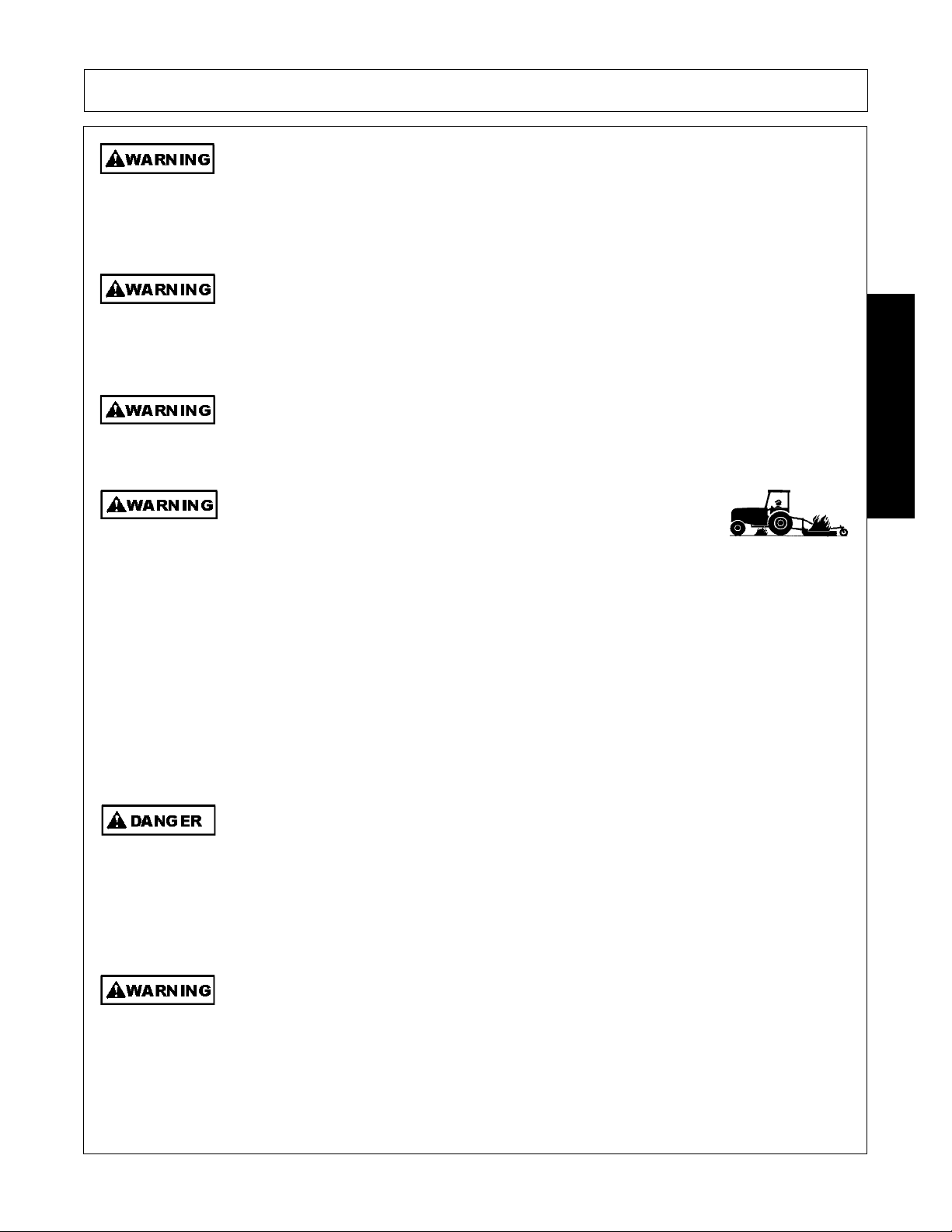
Be particularly careful when transporting the Implement with the Tractor. Turn curves or go
up hills only at a low speed and using a gradual steering angle. Rear mounted implements
move the center of gravity to the rear and remove weight from the front wheels. Make
certain, by adding front ballast, that at least 20 % of the tractor’s weight is on the front wheels
to prevent rearing up, loss of steering control or Tractor tip-over. Slow down on rough or
uneven surfaces to prevent loss o f steering control which could result in property damage
or possible injury. Do not transport unless 3-Point lift lever is fully raised and in the latched
transport position. Dropping implement in transport can cause serious damage to the
tractor and/or Implement and possibly cause the operator or others to be injured or killed.
(S3PT-02)
Allow sufficient clearance for the Implement to swing outward while turning. Implements
carried behind the Tractor will swing outside the tire path when making turns. Contacting a
solid object while turning will cause equipment damage and possible injury.
(S3PT-20)
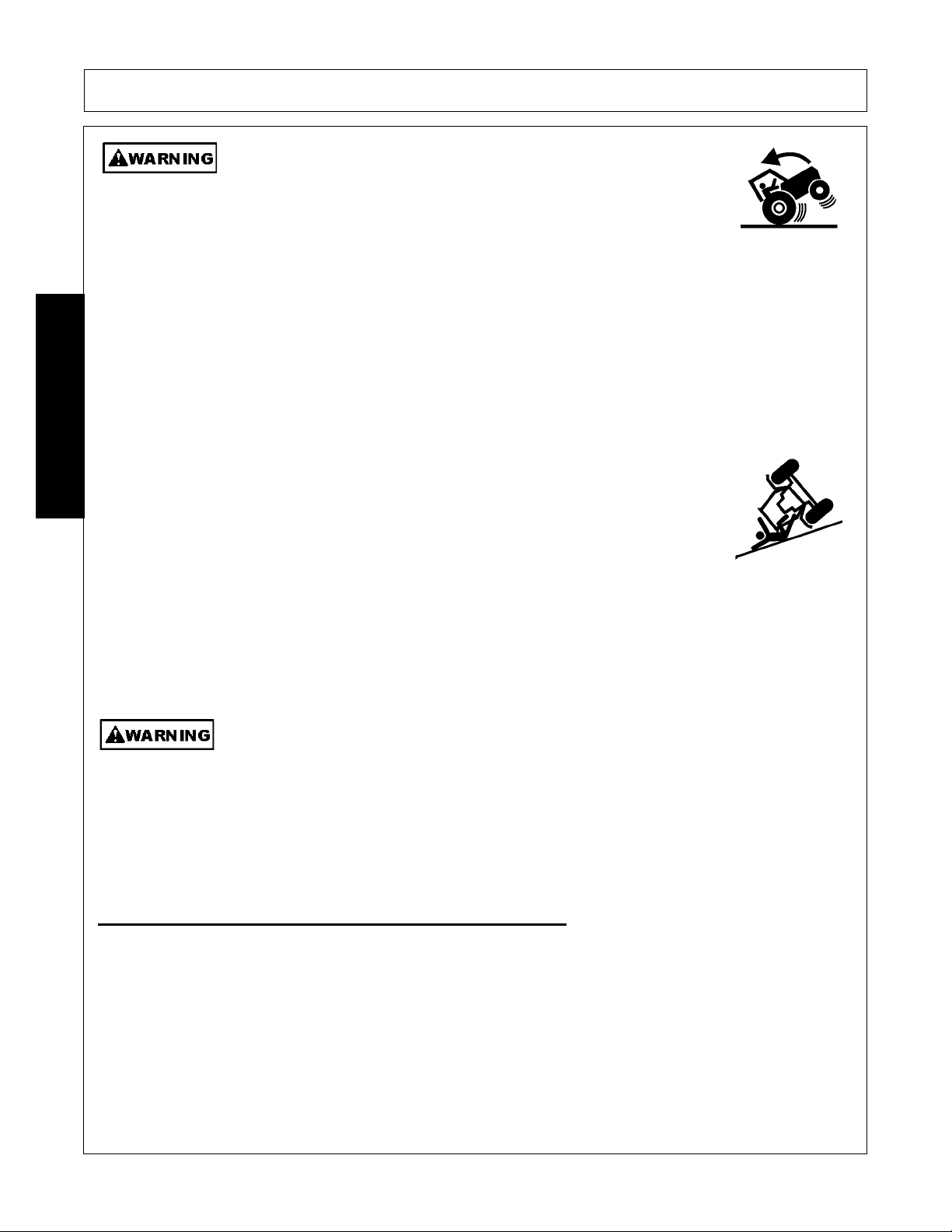
Be particularly careful in transport. The Mower has raised the center of
gravity for the tractor and has increased the possibility of overturn.
Turn curves or go up slopes only at low speed and using a gradual
turning angle. Slow down on rough or uneven surfaces.
(SBM-3)
SAFETY
Transporting Safety Instructions and Practices
RMB 1660 11/10 Safety Section 1-14
© 2010 Alamo Group Inc.
Page 21
SAFETY
When transporting Boom Mower on a truck or trailer, the height or width
may exceed legal limits when the boom is in the transport position.
Contact with side or overhead structures or power lines can cause
property damage or serious injury or death. If necessary lower boom to
reduce height and/or remove mowing head to reduce width to the legal
limits.
(SBM-8)
Never operate the Tractor and Mower Unit without an OPS (Operators
Protective Structure) or Cab to prevent injury from objects thrown from
ground or from overhead trimming. Stop mowing if workers or passersby
are within 300 feet.
(SBM-9)
Make sure the Rotor Control Lever is in the OFF position and control lever locking
mechanism is in the “Locked” Position to prevent ac cid en tal movemen t.
(SBM-26)
Make certain that the “Slow Moving Vehicle” (SMV) sign is installed in
such a way as to be cl early visible and legible. When transport ing the
Equipment use the Tractor flashing warning lights and follow all local
traffic regulations.
(SG-6)
Secure the boom and mower head in the transport position before traveling on public roads.
Never transport on public roads with the boom and mower head extended. Always
disengage and lock out the hydraulic controls for the boom mower before transporting.
Inadvertent boom movement on public roads may contact with other vehicles resulting in
serious bodily injuries or even death.
(SBM-21)
SAFETY
RMB 1660 11/10 Safety Section 1-15
© 2010 Alamo Group Inc.
Page 22
SAFETY
Transport only at speeds where you can maintain control of the
equipment. Serious accidents and injuries can result from operating this
equipment at high speeds. Understand the Tractor and Implement and
how it handles before transporting on streets and highways. Make sure the Tractor steering
and brakes are in good condition and operate properly.
Before transporting the Tractor and Implement, determine the proper transport speeds for
you and the equipment. Make sure you abide by the following rules:
Test the tractor at a slow speed and increase the speed slowly. Apply the Brakes smoothly
to determine the stopping characteristics of the Tractor and Implement. As you increase
the speed of the Tractor the stopping distance increases. Determine the maximum
transport speed not to exceed 20 mph (30 kph) for transporting this equipment.
Test the equipment at a slow speed in turns. Increase the speed through the turn only after
you determine that the equipment can be operated at a higher speed. Use extreme care
and reduce your speed when turning sharply to prevent the tractor and implement from
turning over. Determine the maximum turning speed for you and this equipment before
operating on roads or uneven ground.
Only transport the Tractor and Implement at the speeds which allow you to properly control
the equipment.
Be aware of the operating conditions. Do not operate the Tractor with weak or faulty brakes
or worn tires. When operating down a hill or on wet or rain slick roads, the braking distance
increases: use extreme care and reduce you r speed. When operating in traffic always use
the Tractor’s flashing warning lights and red uce your speed. Be a ware of traf fic around yo u
and watch out for the other guy.
(SG-19)
Your driving vision may be reduced or impaired by the tractor, cab, or implement. Before
driving on public roadways identify any limited vision areas, and make adjustments to your
operating position, mirrors, and the implement transport position so that you can clearly
see the area where you will be traveling, and any traffic that may approach you. Failure to
maintain adequate vision of the public roadway and traffic can result in serious injury or
even death.
(STI-10)
In addition to the design and configuration of this Implement, including Safety Signs and Safety Equipment,
hazard control and accident prevention are dependent upon the awareness, concern, prudence, and proper
training of personnel involved in the operation, transport, maintenance, and storage of the machine. Refer
also to Safety Messages and operation instruction in each of the appropriate sections of the Tractor and
Equipment Manuals. Pay close attention to the Safety Signs affixed to the Tractor and Equipment.
(SG-18)
SAFETY
Concluding Safety Instructions and Practices
RMB 1660 11/10 Safety Section 1-16
© 2010 Alamo Group Inc.
Page 23

SAFETY
Decal Location
NOTE: Bush Hog supplies safety decals on this product to promote safe operation. Damage to the decals may
occur while in shipping, use, or recondition ing. Bush Hog cares about the safety of its customers, operators,
and bystanders, and will replace the safety decals on this product in the field, free of charge (some shipping
and handling charges may apply). Contact your Bush Hog dealer to order replacement decals.
SAFETY
RMB 1660 11/10 Safety Section 1-17
© 2010 Alamo Group Inc.
Page 24

SAFETY
ITEM PART NO. QTY LEVEL DESCRIPTION
1. D433 1 Decal Sheet Multiple Hazard
2. D388 1 Decal Sheet Driveline Hazards
3. D355 1 IMPORTANT Check Chains
4. 02962764 6 WARNING Pinch Points/Scissors
5. 02962765 1 DANGER Multiple Hazard/Crushing
6. 02965262 1 WARNING Oil Leaks
7. D354 1 DANGER Crushing Hazard
8. 50065309 1 LOGO Bush Hog Logo (14.85”)
9. 50068740 2 NAME RMB 1660 Model Name
10. 50061049 1 LOGO Bush Hog Logo (22”)
11. D524 1 BOOKLET Safety Booklet
12. 46505.01 1 _________ Canister (Operator’s Manual Inside)
SAFETY
13. 9313043 3 _________ Bolt
14. 9100103 3 _________ Flatwasher
15. 9143003 3 _________ Locknut
16. 46503.01 1 _________ Seal
17. 46505.01 1 _________ Operators Manual
18. 83380 1 REFLECT SMV Sign
19. NFS 1 SER PLT Serial Number Plate
20. 50068816C 1 _________ Operator’s Manual
21. D568 1 DANGER Operate with Enclosed Cab (Inside Cab)
22. D569 1 WARNING Operate Only with Cab Tractor
23. 10069088 4 _________ Pop Rivet
RMB 1660 11/10 Safety Section 1-18
© 2010 Alamo Group Inc.
Page 25

SAFETY
SAFETY
ITEM PART NO. QTY LEVEL DESCRIPTION
1. 50061049 1 LOGO Bush Hog Logo (22”)
2. 24028 1 WARNING Rubber Deflectors
3. 02965141 1 WARNING Thrown Objects
4. 1290738 1 INSTRUCT Euro Multi-Instruction Flail Head
5. 09.821.35 1 MULTI-DECAL Euro Multi-Instruction
6. 1458392 1 REFLECT Red Reflector
7. 1458393 1 REFLECT Yellow Reflector
8. 41.094.14 1 SERIAL PLATE Serial Number Plate
9. 09.810.01 2 INSTRUCT Grease 8 Hours
RMB 1660 11/10 Safety Section 1-19
© 2010 Alamo Group Inc.
Page 26

Decal Description
Multi Hazard Decal Sheet
P/N D433
Decal D433 consists of the following multi-hazards.
SAFETY
SAFETY
RMB 1660 11/10 Safety Section 1-20
© 2010 Alamo Group Inc.
Page 27
Driveline Hazards
P/N D388
Decal D388 consists of the following multi-hazards.
SAFETY
SAFETY
RMB 1660 11/10 Safety Section 1-21
© 2010 Alamo Group Inc.
Page 28
SAFETY
IMPORTANT! Keep Sway Bar Chains Tight
P/N D355
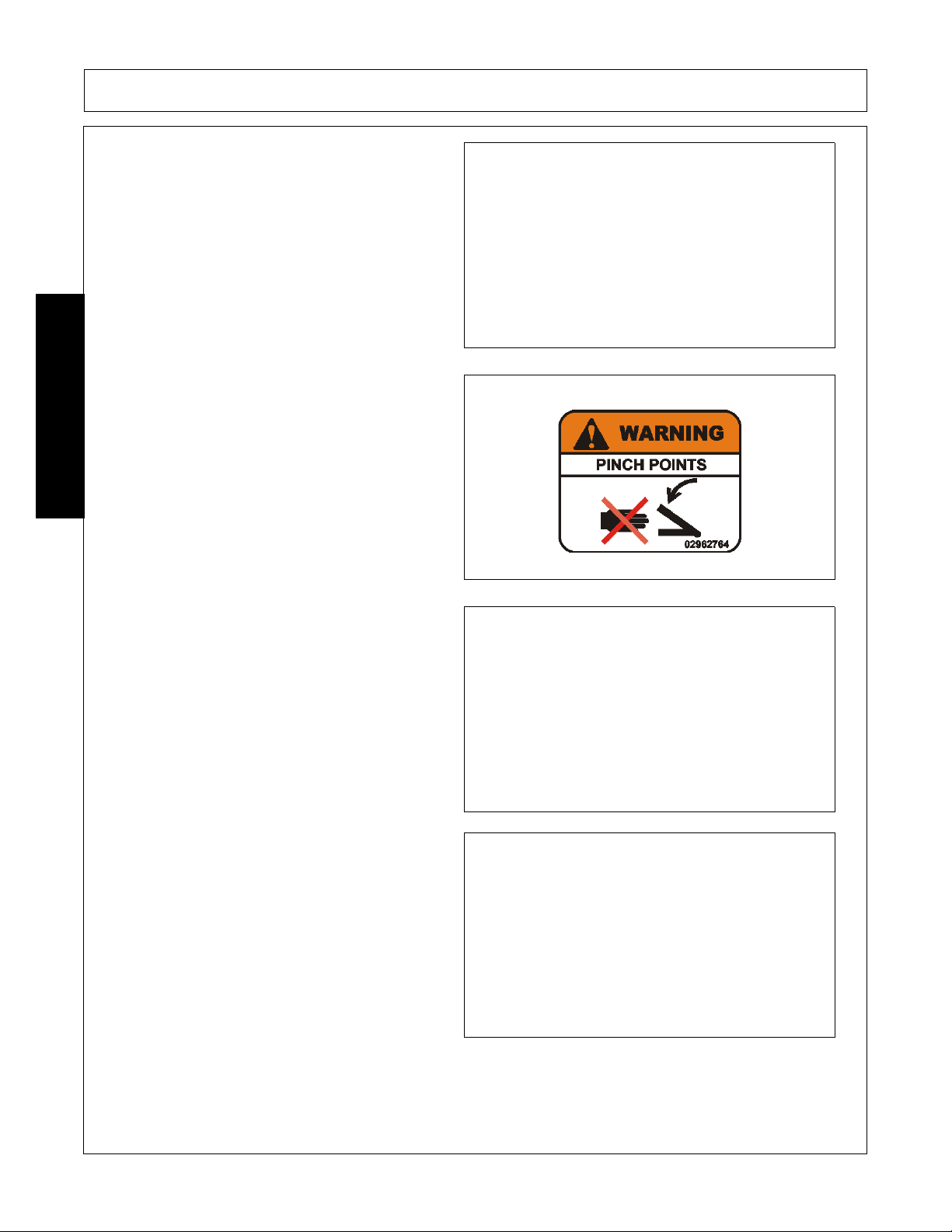
WARNING! Pinch Points
P/N 02962764
DANGER! Crushing and Pinch Points.
Moving machinery parts can pinch or crush or fallwhich may cause injury or death.
P/N 02962765
WARNING! Failure to INSPECT and REPAIR or
REPLACE Hoses may allow worn Hoses to rupture
SUDDENLY and VIOLENTLY with resulting serious
BODILY INJURY from SCALDING or FIRE with
resulting BURN INJURY or DEATH.
P/N 02965262
SAFETY
RMB 1660 11/10 Safety Section 1-22
© 2010 Alamo Group Inc.
Page 29

SAFETY
DANGER! Crushing Hazard
Serious injury can result from contact with moving
boom. Stay clear of boom swing are.
P/N D354
P/N 50065309
Logo Product Name: Bush Hog (14.85”)
P/N 50068740
MODEL NAME - RMB 1660
P/N 50061049
Logo Product Name: Bush Hog (22”)
SAFETY
RMB 1660 11/10 Safety Section 1-23
© 2010 Alamo Group Inc.
Page 30
SAFETY
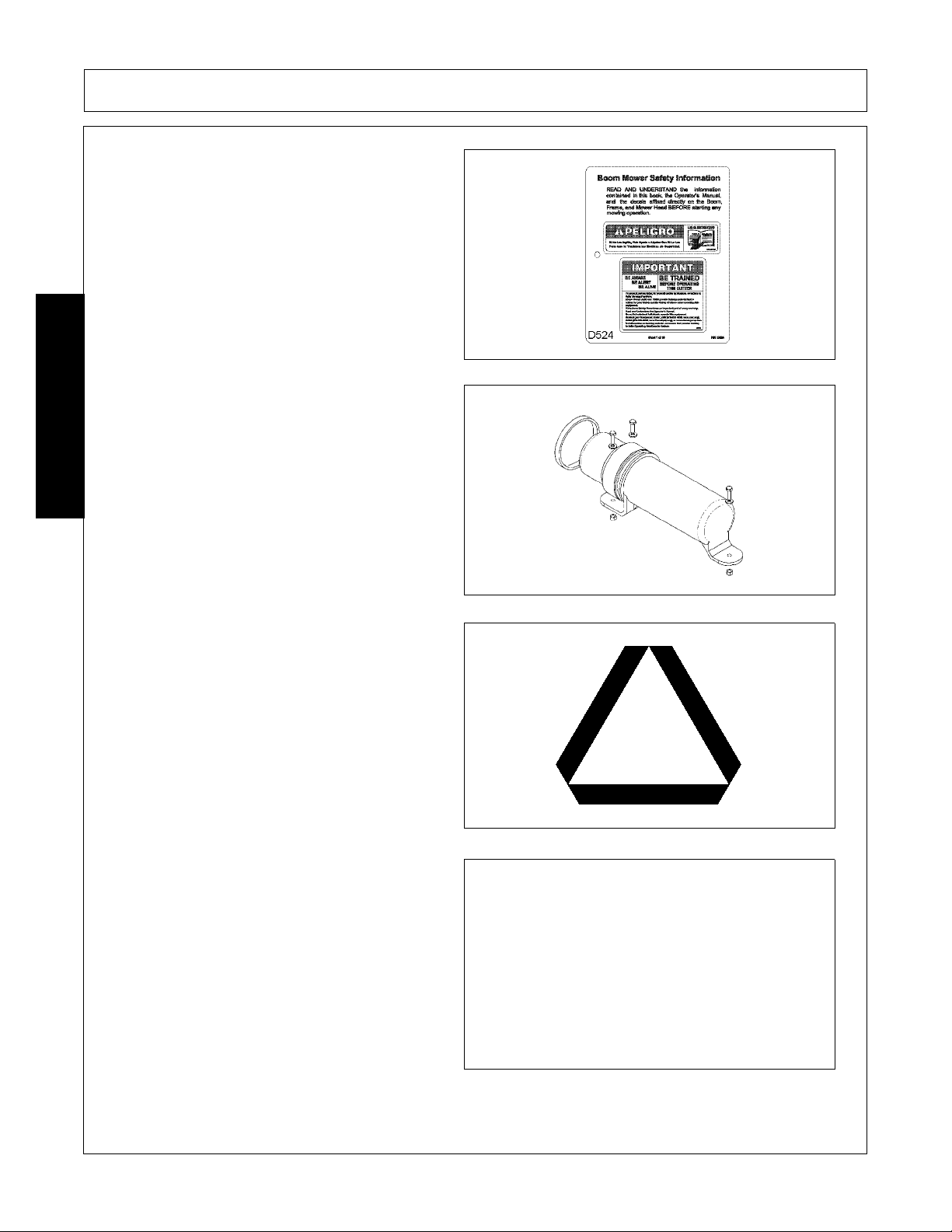
INFORMATION - Safety Booklet
D524
Read Operator’s Manual! The operator’s manual is
located inside this canister. If the manual is
missing order one from your dealer.
P/N 46505.01
Slow Moving Vehicle Decal. Keep SMV reflector
clean and visible. DO NOT transport or operate
without the SMV.
P/N 83380
TO AVOID SERIOUS INJURY OR DEATH only
operate when inside a fully enclosed Tractor CAB.
P/N D568
SAFETY
RMB 1660 11/10 Safety Section 1-24
© 2010 Alamo Group Inc.
Page 31

SAFETY
TO AVOID SERIOUS INJURY OR DEATH only
operate on Tractor equipped with fully enclosed
CAB.
P/N D569
WARNING! Inspect Rubber Deflector and replace
if damaged or noticeably worn. Do not operate
mower if deflector is missing or damaged.
P/N 24028
WARNING! - Cutting while Flail Head is raised off
ground will allow high-speed Flail Blades to throw
cuttings at high speed for a considerable distance.
Thrown objects can cause serious bodily injury.
Stop mowing when traffic, crew members, or
passerby are within 100 yards of the mowing with
head off ground.
P/N 02965141
Euro Flail Multi Decal
P/N 1290738
SAFETY
RMB 1660 11/10 Safety Section 1-25
© 2010 Alamo Group Inc.
Page 32

SAFETY
Euro Multi Decal
P/N 09.821.35
Red Reflector. Keep reflectors clean and visible.
P/N 1458392
Amber Reflector. Keep reflectors clean and visible.
P/N 1458393
Grease 8 Hours
P/N 09.810.01
SAFETY
RMB 1660 11/10 Safety Section 1-26
© 2010 Alamo Group Inc.
Page 33

SAFETY
Federal Laws and Regulations
This section is intended to explain in broad terms the concept and effect of federal laws and regulations concerning
employer and employee equipment operators. This section is not intended as a legal interpretation of the law and
should not be considered as such.
Employer-Employee Operator Regulations
U.S. Public Law 91-596 (The Williams-Steiger Occupational and Health Act of 1970) OSHA
This Act Seeks:
“...to assure so far as possible every working man and woman in the nation safe and healthful working
conditions and to preserve our human resources...”
DUTIES
Sec. 5 (a) Each employer(1) shall furnish to each of his employees employment and a place of employment which are free from
recognized hazards that are causing or are likely to cause death or serious physical harm to his employees;
(2) shall comply with occupational safety and health standards promulgated under this Act.
(b) Each employee shall comply with occupational safety and health standards and all rules, regulations and
orders issued pursuant to this Act which are applicable to his own actions and conduct.
OSHA Training Requirements
Title 29, Code of Federal Regulations Part 1928.57(a)(6). www.osha.gov
Operator instructions. At the time of initial assignment and at least annually thereafter, the employer shall
instruct every employee who operates an agricultural tractor and implements in the safe operating practices
and servicing of equipment with which they are or will be involved, and of any othe r practices dictated by the
work environment.
Keep all guards in place when the machine is in operation;
Permit no riders on equipment
Stop engine, disconnect the power source, and wait for all machine movement to stop before servicing,
adjusting, cleaning or unclogging the equip ment, except where the machine must be running to be properly
serviced or maintained, in which case the employer shall instruct employees as to all steps and procedures
which are necessary to safely service or maintain the equipment.
Make sure everyone is clear of machinery before starting the engine, engaging power, or operating the
machine.
Employer Responsibilities:
To ensure employee safety during Tractor and Implement operation, it is the employer’s responsibility to:
1. Train the employee in the proper and safe operation of the Tractor and Implement.
2. Require that the employee read and fully understand the Tractor and Implement Operator’s manual.
3. Permit only qualified and properly trained employees to operate the Tractor and Implement.
4. Maintain the Tractor and Implement in a safe operational condition and maintain all shields and guards on the
equipment.
5. Ensure the Tractor is equipped with a functional ROPS and seat belt and require that the employee ope rator
securely fasten the safety belt and operate with the ROPS in the raised position at all times.
6. Forbid the employee operator to carry additional riders on the Tractor or Implement.
7. Provide the required tools to maintain the Tractor and Implement in a good safe working condition and provide the
necessary support devices to secure the equipment safely while performing repairs and service.
8. Require that the employee operator stop operation if bystanders or passersby come within 300 feet.
Child Labor Under 16 Y ear s of Age
Some regulations specify that no one under the age of 16 may ope rate power machinery. It is your responsibility to
know what these regulations are in your own area or situation. (Refer to U.S. Dept. of Labor, Employment Standard
Administration, Wage & Home Division, Child Labor Bulletin #102.)
RMB 1660 11/10 Safety Section 1-27
© 2010 Alamo Group Inc.
SAFETY
Page 34

Page 35

INTRODUCTION SECTION
© 2010 Alamo Group Inc.
Introduction Section 2-1
Page 36

INTRODUCTION
This Hydraulic Boom Mower is designed with care and built with quality materials by skilled workers. Proper
assembly, maintenance, and operating practices, as described in this manual, will help the owner/operator get
years of satisfactory service from the machine.
The purpose of this manual is to familiarize, instruct, and train. The Assembly Section instructs the owner/
operator in the correct assembly of the Mower using standard and optional equipment. The Parts Listing
section is designed to familiarize the owner/operator with replaceable parts on the Mower. This section
provides exploded assembly drawings of each mower component illustrating each piece and the
corresponding part number.
Careful use and timely service saves extensive repairs and costly downtime losses. The Operation and
Maintenance Sections of the manual train the owner/operator how to work the Mower correctly and attend to
appropriate maintenance. The Troubleshooting Guide helps diagnose difficulties with mower and offers
solution to the problems.
Safety is of primary importance to the owner/opera tor and to the ma nufa cturer. The first section of this manual
includes a list of Safety Messages, that, if followed, will help protect the operator and bystanders from injury or
death. Many of the Safety Messages will be repeated throughout the manual. The owner/operator/dealer
should know these Safety Messages befor e assembly and be aware of the hazards of operating this mo wer
during assembly, use, and maintenance. The Safety Alert Symbol combined with a Signal Word, as seen
below, is intended to warn the owner/operator of impe nding hazards and the deg ree of possible injury faced
INTRODUCTION
when operating this machine.
Indicates an imminently hazardous situation that, if not avoided, WILL result in DEATH OR
VERY SERIOUS INJURY.
Indicates an imminently hazardous situation that, if not avoided, COULD result in DEATH
OR SERIOUS INJURY.
Indicates an imminently hazardous situation that, if not avoided, MAY result in MINOR
INJURY.
Identifies special instructions or procedures that, if not strictly observed, could result in
damage to, or destruction of the machine, atta ch me nts or the en vir on m en t.
NOTE: Identifies points of particular interest fo r more efficient and convenient operation or repair.
RMB 1660 11/10 Introduction Section 2-2
© 2010 Alamo Group Inc.
Page 37

INTRODUCTION
INTRODUCTION
The Bush Hog Boom Mower is primarily designed for grass cutting and trimming hedges. This mower is
assembled for operation with 540 RPM tractor input only. With proper use and maintenance the mower should
provide years of dependable service.
For Non-Agricultural use, OSHA, ASABE, SAE and ANSI standards require the use of Chain
Guards, Deflectors, or Solid Skirts at all times. The Mower manufacturer strongly
recommends the use of Chain Guards, Deflectors, or Solid Skirts for Agricultural purposes
as well to reduce the risk of property damage, serious bodily injury, or even death from
objects thrown out by or from contact with the Cu tting Blades.
At least 20% of the tractor’s total weight must be on the front tires with the Mower lifted to
provide adequate traction for safe steering under good conditions. Slow down on hills, rough
terrain, and curves.
Mower Orientation: Front and rear, and left and right are determined by the normal direction of travel (the same
as on your automobile).
RMB 1660 11/10 Introduction Section 2-3
© 2010 Alamo Group Inc.
Page 38

INTRODUCTION
ATTENTION OWNER/ OPERATOR
BEFORE OPERATING THIS MACHINE:
1. Carefully read the Operator’s Manual, completely understand the Safety Messages and instructions, and
know how to operate correctly both the Mower and Power Unit.
2. Fill out the Warranty Card in full. Be sure to answer all questions, including the Serial Number of the Mower.
Mail promptly using the return envelope included with the Operator’s Manual.
NOTE: Warranties are honored only if completed “Owner Registration and Warranty” forms are received by
Alamo Group within thirty days of delivery of the mower.
3. Record the Mower Model and Serial Numbers on the Warranty page at the end of the Operator’s Manual.
Keep this as part of the permanent maintenance file for the Mower.
INTRODUCTION
RMB 1660 11/10 Introduction Section 2-4
© 2010 Alamo Group Inc.
Page 39

ASSEMBLY SECTION
© 2010 Alamo Group Inc.
Assembly Section 3-1
Page 40

ASSEMBLY
TRACTOR SELECTION
MINIMUM TRACTOR WEIGHTS - including ballast weight if necessary:
All models – 6,600 lbs.
MINIMUM HP REQUIREMENTS:
All models – 60 PTO HP
LINKAGE:
Category 2
P.T.O. SHAFT:
Tractor must be equipped with a live drive PTO to enable forward motion to be stopped while the flail head
continues to operate.
CHECK CHAINS/STABILIZERS:
Check chains or stabilizers must be fitted and tightened.
ASSEMBLY
TRACTOR OPERATOR STATION:
Bush Hog recommends installing the 1660 Boom Mower on fully enclosed cab tractors equipped with
impact resistant glass windows. Do Not Operate if Tractor Cab is damaged.
RMB 1660 11/10 Assembly Section 3-2
© 2010 Alamo Group Inc.
Page 41

ASSEMBLY
TRACTOR PREPARATION
Fitting Operator Guard
Use tractor with safety glass windows if possible and fit Operator guard using the hooks pr ovided. Shape mesh
to cover all vulnerable areas. Remember the driver must be looking through mesh and/or poly carbonate
glazing when viewing the flail head in any working position - unless the tractor/cab manufacturer can
demonstrate that the penetration resistance is equivalent to, or higher than, that provided by mesh/poly
carbonate glazing.
ASSEMBLY
Wheel Width: Set wheel widths as wide as possible.
Lift Links: Adjust lift links until they are equal length.
Tractor Ballast: It is imperative when attaching ‘third-party’ equipment to a tractor that the maximum possible
stability of the machine and tractor combination is achieved – this can be accomplished by the utilization of
‘ballast’ in order to counter-balance the additional equipment added.
Front weights may be required to place 20% of total outfit weight on the front axle for stable transport on the
road and to reduce ‘crabbing’ due to the drag of the cutting unit when working on the ground.
Rear weights may be required to maintain a reasonable amount of rear axle load on the opposite wheel from
the arms when in work; for normal off-ground work i.e. hedge cutting this should be 20% of rear axle weight or
more for adequate control, and for ground work i.e. grass mowing with experienced operators, this can be
reduced to 10%. All factors must be addressed in order to match the type and nature of the equipment added
to the circumstances under which it will be used. The center of gravity on a RMB 1660 will constantly change
as the boom or cutting attachment moves. Maintaining proper balance during operation and transport is critical.
Factors that affect stability:
• Center of gravity of the tractor/machine combination.
• Geometric conditions, e.g. position of the cutting head and ballast.
• Weight, track width and wheelbase of the tractor.
• Acceleration, braking, turning and the relative position of the cutting head during these
• operations.
• Ground conditions, e.g. slope, grip, load capability of the soil/surface.
• Rigidity of implement mounting.
RMB 1660 11/10 Assembly Section 3-3
© 2010 Alamo Group Inc.
Page 42

ASSEMBLY
Suggestions to increase stability:
• Increasing rear wheel track; a tractor with a wider wheel track is more stable.
• Ballasting the wheel; it is preferable to use external weights but liquid can be added to around 75% of the
tire volume – water with anti-freeze or the heavier Calcium Chloride alternative can be used.
• Addition of weights – care should be t aken in selecting th e location of the weight s to ensure th ey are added
to a position that offers the greatest advantage.
• Front axle locking; a cylinder can be used to ‘lock’ the front axle in work only – locking the axle moves the
‘balance line’ and can be used to transfer weight to the front axle from the rear (check with tractor
manufacturer).
The advice above is offered as a guide for stability only and is not a guide to tractor strength - it is therefore
recommended that you consult your tractor manufacturer or local dealer to obtain specific advise on this
subject, additionally advice should be sought from a tire specialist with regard to tire pressures and rat ings
suitable for the type and nature of the machine you intend to fit.
DEALER SETUP INSTRUCTIONS
ASSEMBLY
1. The machine will be delivered in a partially
dismantled condition, secured with transport
strap and banding.
2. Choose a firm level site.
3. Remove the transport strap, banding straps and
loose items.
4. Check the oil level.
5. Raise the machine using overhead lifting
equipment with a minimum capacity of 3307
lbs. LEAVE IN POSITION AT THIS STAGE.
6. Lower the legs and pin in posit ion selecting the
holes that position the machines gearbox stub
shaft approx. 3” below the tractors P .T . O. shaft.
NOTE: Leg pin position used.
7. Unbolt stabilizer from machine and remove the
stabilizer nose quadrant pin.
RMB 1660 11/10 Assembly Section 3-4
© 2010 Alamo Group Inc.
Page 43

ASSEMBLY
ATTACHMENT TO TRACTOR
• Reverse tractor squarely up to the machine.
• Connect the tractors sway bars - selecting the
rear most hole in the machines lower link
brackets that allow the machine to be m ounted
without contacting the tractor.
• Ensure that the same hole is used on both
sides.
• If necessary fit the spacers supplied (as
required) to minimise sideways movement of
the tractor sway bars within the hitch brackets.
• Tighten tractor’s stabilizers.
• The lifting equipment may now be removed.
• Fit the stabilizer tongue (A or B) into the tractors
top link position. Use the highest position
available avoiding any load sensing properties.
• The bolt-on tongue of the stabilizer is reversible
to accommodate a variety of tractor linkage
designs.
• Stretch out the stabilizer and rest the bottom
legs on the lower rail.
ASSEMBLY
• Do not fit stabilizer lower pins at this stage.
RMB 1660 11/10 Assembly Section 3-5
© 2010 Alamo Group Inc.
Page 44

• Fit the machine to top link
ASSEMBLY
ASSEMBLY
• Raise machine on tractor linkage until the tractors
PTO and the machines gearbox stub shaft are
approximately in line.
NOTE: As lift occurs be aware the machine may tilt
slightly.
The four levers of machine controls must be operated from the tractor seat. During this
operation ensure no one is standing on or among the linkage arms or bars. Set tractor
hydraulics to position control. Never allow anyone below the frame unless it is securely
blocked up.
RMB 1660 11/10 Assembly Section 3-6
© 2010 Alamo Group Inc.
Page 45

ASSEMBLY
• Replace the stabilizer quadrant pin and secure with
the clip pin.
NOTE: The quadrant pin must be fitted in the lowest
hole on the stabilizer in order that it acts as a “Bottom
Stop”. This will prevent the machine from dropping
when stopped and permit the tractor’s in-built transport
protection system to function correctly during operation
and transportation.
• Ensure the tractor’s linkage is in “Position Control”
and the linkage raised sufficiently to hold the sickle
bar at the correct height and remove the load from
the quadrant pin
ASSEMBLY
NOTE: Never fit the quadrant pin in a location hole that
locks the stabilizer as this can cause damage to the
machine and/or tractor.
• Adjust the top link to bring the machine frame int o
the vertical position.
RMB 1660 11/10 Assembly Section 3-7
© 2010 Alamo Group Inc.
Page 46

ASSEMBLY
Check that the welded in pins between the stabilizers jaws are in contact with the mounting rail. If not the
machine must be lowered to the ground and the next higher hole on the stabilizer valve selected, the machine
raised and contact checked. Repeat again in the third hole if necessary. On subsequent fitting to the same
tractor the hole selected is always used.
ASSEMBLY
• Adjust the top link to bring the frame of the
machine into the vertical position.
RMB 1660 11/10 Assembly Section 3-8
© 2010 Alamo Group Inc.
Page 47

ASSEMBLY
• Adjust using the mounting hole that allows the
P.T.O. and gearbox shaft to align as near as
possible.
• Fit positioning stops - these remain in position
until tractor is changed
ASSEMBLY
• Lower tractor linkage control so that the
machine weight is taken by the yoke.
RMB 1660 11/10 Assembly Section 3-9
© 2010 Alamo Group Inc.
Page 48

• Raise the stand legs into the work position and
secure with lock pins.
ASSEMBLY
• Tighten check chains and/or stabilizer bars.
ASSEMBLY
• Fit machine controls into the cab.
• Measure P.T.O. and cut to dimension shown.
Note: For subsequent use on different tractors
measure again - there must be a minimum shaft
overlap of 6”.
RMB 1660 11/10 Assembly Section 3-10
© 2010 Alamo Group Inc.
Page 49

ASSEMBLY
Do Not attempt to raise or lower the boom or mower head unless the Implement is secure ly
attached to the Tractor. The Implement could tip over and cause equipment damage and
possible serious injury or death. Do Not use the boom controls to assist in installing the
implement on the tractor. Raise or Lower the boom and mower head only while seated in
the Tractor operator’s seat with the seat belt securely fastened. Inadvertent contact with
the boom controls could allow a component to fall. A sudden or inadvertent fall by any of
these components could cause serious injury or even death.
(SBM-23)
• Fit PTO shaft in position.
• Attach safety chains (A) on driveline to a
convenient location to prevent rotation of the
shaft guarding.
ASSEMBLY
• Ensure the Lift Cylinder shut-off valve and Slew
Cylinder shut-off valve are open.
• Operate the lift up controls and raise the dipper
arm end just enough to clear the ground.
• Pivot out the dipper arm until the tension link can
be connected.
RMB 1660 11/10 Assembly Section 3-11
© 2010 Alamo Group Inc.
Page 50

Flail Head Attachment
Operate machine controls to maneuver boom arm
into flailhead attachment. The bottom of the hose
connection bracket must be parallel with the
ground. Refer to torque chart for correct bolt torque
settings.
ASSEMBLY
ASSEMBLY
With the arms at half reach and the flailhead clear of the ground carry out final adjustment of the lift arm
leveling box to bring the main frame horizontal. Carefully operate the machine through its full range of
movements while checking that the hoses are not strained, pinched, chaffed or kinked and that all movements
are functioning correctly. Fold the machine into the transport position. The machine is now ready to proceed to
the work site.
RMB 1660 11/10 Assembly Section 3-12
© 2010 Alamo Group Inc.
Page 51

ASSEMBLY
OIL REQUIREMENTS
Tank
Fill reservoir to approximately 2” below the top of the tank. The capacity is approximately 180 liters (47.5
gallons). Do not overfill the tank.
Supplier Cold or Temperature Climate Hot Climate
Castrol Agricastrol hydraulic oil
Hy-spin AWS46
Shell Tellus 46 Tellus 68
Mobil D.T.E. 25 D.T.E. 26
Esso Nuto “H” or “A” 46 Nuto “H” or “A” 68
Texaco Rando HD 46 Rando D 68
Gulf Hydrasil 46 Hydrasil 68
B.P. Energal HLP 46 Energal HLP 68
Dalton Silkolene Dove 46 or
Derwent 46
Elf Hydrelf 46 Hydrelf 68
FITTING CONTROL UNIT IN CAB
Cable Controlled Models
ASSEMBLY
Hy-spin AWS68
Silkolene Dove 68
or Derwent 68
The control unit is bolted to a mounting bracket.
This bracket may be bolted to the fender or cab bracket in a convenient location ensuring that no structural
member of the cab or roll bar is drilled.
In deciding the final position of the control box remember not to exceed the minimum acceptable bend -radii of
8"' for the cables.
The control lever for the cable operated rotor control valve is mounted in a similar fashion adopting the same
precautions pertaining to drilling and cable runs.
RMB 1660 11/10 Assembly Section 3-13
© 2010 Alamo Group Inc.
Page 52

ASSEMBLY
RUNNING UP PROCEDURE
1. Ensure that the rotor control valve is in "STOP" position, start tractor, engage P.T.O. allow the oil to
circulate through the return line filter for about 5 minutes without operation of the armhead control lever.
2. Operate the armhead levers through their complete range ensuring that all movements are functioning
correctly.
3. Place the flail head at a safe attitude and move the ro tor control to "START" position. After initial fluctuation
the rotor should settle to a steady speed. Increase P.T.O. speed to approximately 360 rpm. and run for a
further five minutes before disengagin g an d stoppin g tr act or.
4. Check the hose runs and observe that they are free from an y pinching, chafing, straining or kinks. Recheck
the oil level in the tank and top up as necessary.
Do not allow the pump to continue working if the rotor does not turn. Overheating and
serious pump damage to the pump can be caused in a very short time.
5. After running up the machine, increase PTO speed to approximately 360 RPM. Run machine further for
ASSEMBLY
five minutes before disengaging the PTO and stopping tractor. The reason for this running period under a
no load condition is to thoroughly circulate the oil in the reservoir through the return line filter.
6. Check the hose runs and observe that they are free from an y pinching, chafing, straining or kinks. Recheck
the oil level in the tank and top up as necessary.
REMOVAL FROM TRACTOR
Read carefully before commencing to remove the machine from the tractor.
The order of the following steps must be followed exactly. Disconnecting the top link must be the last operation
prior to driving the tractor away from the machine.
Do not operate valve lever or machine cont rols through the re ar cab window while standing
on or among linkage components. Always seek assist ance.
• Select a firm level site for parking the machine.
• Replace parking legs in their sockets and secure in their lowest position.
• Raise the machine on the tractor linkage until the weight is taken off the stabilizer.
• Remove the lower stabilizer pins.
• Unscrew the lift cylinder hydraulic shut-off valve.
• Lower the machine to be ground.
• Extend the arms and place the flail head on the ground at half reach.
• Disengage tractor PTO and remove.
• Disconnect stabilizer bars or loosen check chains as applicable.
• Unbolt the control unit from the mounting bracket, remove from tractor cab and stow the levers or
switchbox clear of the ground.
• Disconnect the stabilizer from the tractors top hitch position. Allow the stabilizer to slide along the rail until
it contacts the eccentric stop s.
• Remove draft link pins and drive tractor away from machine.
RMB 1660 11/10 Assembly Section 3-14
© 2010 Alamo Group Inc.
Page 53

ASSEMBLY
STORAGE
If machine is to be left standing for an extended period of time, lightly coat the exposed portions of the cylinder
rods with grease. Subsequently this grease should be wiped off before the rods are moved. If the machine has
to be stored outside tie a piece of tarpaulin or canvas over the control assembly. Do not use a plastic fertilizer
bag which could lead to rapid corrosion.
SUBSEQUENT ATTACHMENT TO IDENTICAL TRACTOR
Refer to and follow steps on ‘initial attachment to tractor’ found on previous pages.
• Connect stabilizer into tractors top hitch position used previously.
• Raise the machine on the tractor linkage until the stabilizer contacts the eccentric stops.
• Fit stabilizer lower pins.
• Mount controls in the tractor cab.
• Fit PTO shaft and attach torque chain to a convenient point to prevent the shaft guard rotating.
• Place arms in work position at half reach and adjust lift arm levelling box to bring frame horizontal.
• Tighten check chains.
• Stow parking legs.
• Fold machine into transport position.
• Proceed to the work site.
SUBSEQUENT ATTACHMENT TO DIFFERENT TRACTOR
• Remove stabilizer and top link from machine and separate.
• Refer to and follow steps ‘initial attachment to tractor’.)
ASSEMBLY
RMB 1660 11/10 Assembly Section 3-15
© 2010 Alamo Group Inc.
Page 54

Page 55

OPERAT ION SECTION
© 2010 Alamo Group Inc.
Operation Section 4-1
Page 56

OPERATION
READ AND UNDERSTAND THE ENTIRE OPERATING INSTRUCTIONS AND SAFETY SECTION OF THIS
MANUAL AND THE TRACTOR MANUAL BEFORE ATTEMPTING TO USE THE TRACTOR AND
IMPLEMENT. If you do not understand any of the instructions, contact your nearest authorized dealer for a
full explanation. Pay close attention to all safety signs and safety messages contained in this manual and
those affixed to the implement and tractor. OPS-U- 0001
READ, UNDERSTAND, and FOLLOW the following Safety Messages. Serious injury or
death may occur unless care is taken to follow the warnings and instructions stated in the
Safety Messages. Always use good common sense to avoid hazards.
(SG-2)
Si no lee ingles, pida ayuda a alguien que si lo lea para que le traduzca las
medidas de seguridad.
(SG-3)
BUSH HOG RMB 1660
OPERATING INSTRUCTIONS
Bush Hog Boom Mowers are manufactured with quality material by skilled workers. These mowers are
designed for cutting grass and small weeds. The mower is equipped with protective deflectors to prevent
objects being thrown from the mower by the blades, however, no shielding is 100% effective. All shields,
guards, and deflectors equipped on the mower must be maintained in good operational condition.
It is the operator’s responsibility to be knowledgeable of all potential operating hazards and to take every
reasonable precaution to ensure oneself, others, animals, and property are not injured or damaged by the
mower, tractor, or a thrown object. Do not operate the mower if passersby, pets, livestock, or property are
within 300 feet of the unit.
This section of the Operator’s Manual is designed to familiarize, instruct, and educate safe and proper mower
use to the operator. Pictures contained in this section are intended to be used as a visual aid to assist in
explaining the operation of a boom mower and are not specific to any model. Some pictures may show shields
removed for picture clarity. NEVER operate implement without all shields in place and in good operational
condition. The operator must be familiar with the mower and tractor and all associated safety practices before
OPERATION
operating the mower and tractor. Proper operation of the mower, as detailed in this manual, will help ensure
years of safe and satisfactory use of the mower.
IMPORTANT: To avoid mower damage, retorque all bolts after the first 10 hours of operation. Refer to the
Torque Chart at the end of the Maintenance Section to ensure bolts are properly tightened.
RMB 1660 11/10 Operation Section 4-2
© 2010 Alamo Group Inc.
Page 57

OPERATION
1. Standard Equipment and Specifications
Trac tor Requirements:
Minimum Tractor HP Requirements 60 HP PTO
Minimum Tractor Weight 6614lbs (3000kg)
Machine Specifications:
Maximum Machine Reach 16’-5” (5.0m)
Machine weight with flailhead 2434lbs (1104kg)
Power Arm Horsepower 54hp
Oil Tank Capacity 48g (180ltr)
Hydraulics:
Gear Totally Independent Standard
Method of Attachment:
3-Point Linkage-Mounted Standard
Controls:
Cable Control Standard
Machine Equipment:
Safety Breakaway - Hydraulic Standard
Road Light Kit Stan d ard
Power Slew Standard
Cable Rotor Control Standard
Window Guards Standard
OPERATION
Power Arm Attachments:
Flail Mower
Sicklebar Mower
RMB 1660 11/10 Operation Section 4-3
© 2010 Alamo Group Inc.
Page 58

OPERATION
2. OPERATOR REQUIREMENTS
Safe operation of the unit is the responsibility of a qualified operator. A qualified operator has read and
understands the implement and tractor Operator’s Manuals and is experienced in implement and tractor
operation and all associated safety practices. In addition to the safety messages contained in this manual,
safety signs are affixed to the implement and tractor. If any part of the operation and safe use of this
equipment is not completely understood, consult an authorized dealer for a complete explanation.
If the operator cannot read the manuals for themselves or does not completely und erst and the opera tion of the
equipment, it is the responsibility of the supervisor to read and explain the manuals, safety practices, and
operating instructions to the operator.
Safe operation of equipment requires that the operator wear approved Personal Protective Equipment (PPE)
for the job conditions when attaching, operating, servicing, and repairing the equipment. PPE is designed to
provide operator protection and includes the following safety wear:
PERSONAL PROTECTIVE EQUIPMENT (PPE)
• Always Wear Safety Glasses
•Hard Hat
• Steel Toe Safety Footwear
• Gloves
• Hearing Protection
• Close Fitting Clothing
• Respirator or Filter Mask (depends on
operating conditions) OPS-U- 0002
NEVER use drugs or alcohol immediately before or while operating the
Tractor and Implement. Drugs and alcohol will affect an operator’s
alertness and coordination and therefore affect the operator’s ability to
operate the equipment safely. Before operating the Tractor or Implement,
an operator on prescription or over-the-counter medication must consult
a medical professional regard ing any side effects of the medication that
would hinder their ability to operate the Equipment safely. NEVER
knowingly allow anyone to operate this equipment when their alertne ss or
coordination is impaired. Serious injury or death to the operator or others
could result if the operator is under the influen ce of drugs or a lcohol.
(SG-27)
OPERATION
RMB 1660 11/10 Operation Section 4-4
© 2010 Alamo Group Inc.
Page 59

OPERATION
3.1 ROPS and Seat Belt
The tractor must be equipped with a Roll-Over-Protective-Structure (ROPS) (tractor cab or roll-bar) and seat
belt to protect the operator from falling off the tractor, especially during a roll over where the driver could be
crushed and killed. Only operate the tractor with the ROPS in the raised position and seat belt fastened.
Tractor models not equipped with a ROPS and seat belt should have these life saving features installed by an
authorized dealer. OPS-U- 0003
Operate this Equipment only with a Cab Tractor. Always wear seat belts. (SG-45)
3.2 Operator Thrown Object Protection
The tractor must be equipped with protective
equipment to shield the operator from falling and
thrown objects. For cab tractors, the tractor must
be equipped with an operator safety screen on its
right side or the right side windows must be fitted
with a shatter proof safety window. For non-cab
tractors, the tractor must be equipped with a
ROPS and operator protective safety cage that
provides protection to the right and above the
operator seat. DO NOT remove the ROPS from
non-cab tractors to equip a safety cage.
OPS-B- 0001_A
Never operate the Tractor and Mower Unit without an OPS (Operators
Protective Structure) or Cab to prevent injury from objects thrown from
ground or from overhead trimming. Stop mowing if workers or passersby
are within 300 feet.
(SBM-9)
3. TRACTOR REQUIREMENTS
In addition to tractor horsepower and size requir ed to o per ate the m ower unit, th e tra cto r m ust also be pro pe rly
equipped to provide operator protection, to alert approaching vehicle drivers of the tractor’s presence, and to
ensure tractor stability when mowing with the boom fully extended.
Tractor Requirements and Capabilities
• SAE/ISO approved Roll-Over Protective Structure (ROPS) or ROPS cab and seat belt.
• Operator Protection..........................Tractor must be equipped with protective structure such as operator
cage or lexan window to protect operator from thrown object and falling objects
• Tractor Safety Devices ....................Slow Moving Vehicle (SMV) emblem, lighting,
• Tractor Ballast .................................As required to maintain at least 1500 lbs. on left rear tire
OPERATION
RMB 1660 11/10 Operation Section 4-5
© 2010 Alamo Group Inc.
Page 60

OPERATION
3.3 T ractor Lighting and SMV Emblem
If the tractor will be operated near or traveled on a
public roadway it must be equipped with proper
warning lighting and a Slow Moving Vehicle (SMV)
emblem which are clearly visible from the rear of
the unit. Most tractor’s have different settings for
operating and transporting lighting. Refer to the
tractor operator’s manual for using the tractor’s
light switch and operating the turn signals.
OPS-B- 0017
3.4 T ractor Ballast
To ensure tractor stability when operating on flat surfaces the left rear tractor tire MUST exert a minimum
down force (weight) of 1500 lbs. on the ground when the tractor is on level ground, its boom is fully extended
and the mower head is horizontal and two feet above the ground. A tractor that does not meet this criteria is
DANGEROUS and should not be operated as upset of the unit can occur resulting in possible serious injury
and property damage.
If the unit is operated on slopes greater than 5,
additional counterweight will be required.
Operation of the unit on slopes greater than 11
percent (6.4 degrees) is not recommended under
any circumstances. On a tractor with a 96” outside
to outside tire spread, an 11 percent (6.4 degrees)
slope occurs when one rear tractor tire is about 8”
lower than the other rear tire. OPS-B- 0018_C
OPERATION
RMB 1660 11/10 Operation Section 4-6
© 2010 Alamo Group Inc.
Page 61

OPERATION
3.5 Tractor Safety Devices
If transporting or operating the tractor and implement near a pub lic roadway, the tractor must be equipped with
proper warning lighting and a Slow Moving Vehicle (SMV) emblem which are clearly visible from the rear of
the unit. Lights and a SMV emblem must be equipped directly on implements if the visibility of the tractor
warning signals are obscured.
Maintain all manufacturer equipped safety shields and guards. Always replace shields and guards that were
removed for access to connect, service, or repair the tractor or implement. Never operate the tractor PTO
with the PTO master shield missing or in the raised position. OPS-U- 0004
3.6 T ractor Horsepower
The horsepower required to operate the mower depends on many factors includ ing vegetation to be cut, terrain
condition, operator experience, and condition of the mower and tractor. For most mowing condition, the 1660
boom mower requires a tractor with at least 60 HP PTO. Operating the mower with a tractor that does not ha ve
adequate power may damage the tractor engine.
3.7 3-Point Hitch
1660 boom mowers can attach to tractors with a
CAT II hitch. Refer to the tractor operator’s manual
for the category of the tractor used. If the hitch
does not conform to ASABE Cat II dimensions, the
mower may not fit or raise properly. Consult an
authorized dealer for possible modification
procedures to mount nonconforming hitches.
OPERATION
Use the correct hitch pins for the hitch category
being used. For Cat II hitches it requires 1-1/8”
lower and 1” upper diameter hitch pins.
CAT II Implement/ Hitch Specification
Width from outside to outside A-frame.........32-3/8”
Quick Hitch width inside lug to lug...............33-5/8”
Height from bottom hitch pin to top pin..............19”
Lower pin diameter....................... ... .... ... ... ..1-1/18”
Upper pin diameter....................... ... .... ... ... ....... ...1”
Lynch pin diameter........................................15/32”
3.8 Hydraulics
The 1660 is available with a Totally Independent Hydraulic System complete with Rotor Rotation Control. The
rotor can be started, stopped, or reversed by operating a lever on the Control Console.
RMB 1660 11/10 Operation Section 4-7
© 2010 Alamo Group Inc.
Page 62

OPERATION
3.9 Front End Weight
A minimum of 20% total tractor weight must be maintained on the tractor front end at all times. Front end
weight is critical to maintain steering control and to prevent the tractor from rearing up while driving. If the
front end is too light, add weight until a minimum of 20% total weight is reached on the front tires. Front
weights and weight carriers can be purchased throug h an authorized tractor dealership. OPS-U- 0005
3.10 Power Take Off (PTO)
Depending on the unit, the mower is designed to operate at a PTO speed of 540 RPM. Most tractors operate
at either 540, or a combination of 540 and 1000 RPM PTO speeds. The operating speed of the mower and
tractor can be determined by the number of splines on the driveline yoke and PTO output shaft. Those
operating at 540 RPM will have a 6-spline shaft and those operating at 1000 RPM will have a 21-spline shaft.
Note: Refer to the tractor owner’s manual for instructions to change PTO speeds on models that operate at
more than one speed.
If operating an older model tractor where the tractor’s transmission and PTO utilize one master clutch, an
over-running clutch must be used between the PTO output shaft and the driveline of the mower. An
authorized tractor dealer can provide the over-running clutch and its installation if needed. OPS-U- 0006_B
DO NOT use a PTO adapter to attach a non-matching Implement driveline to a Tractor
PTO. Use of an adapter can double the operating speed of the Implement resulting in
excessive vibration, thrown objects, and blade and implement failure. Adapter use will also
change the working length of the driveline exposing unshielded driveline areas. Serious
bodily injury and/or equipment failure can result from using a PTO adapter. Consult an
authorized dealer for assistance if the Implement driveline does not match the Tractor PTO.
(S3PT-14)
Never operate the Tractor and Mower if the Im plement input driveline is directly connected
to the Tractor transmission. Tractor braking distances can be substantially increased by
the momentum of the rotating Mower blades driving the Tractor transmission even though
the Tractor clutch has been d ise ngage d. Install an over running clutch between the Tractor
PTO and the Mower driveline to prevent this potentially dangerous situation.
(S3PT-16)
4. GETTING ON AND OFF THE TRACTOR
Before getting onto the tractor, the operator must read and completely understand the implement and tractor
operator manuals. If any part of either manual is not completely understood, consult an authorized dealer for
a complete explanation. OPS-U- 0007
Do not mount or dismount the Tractor while the tractor is moving. Mount
the Tractor only when the Tractor and all moving parts are completely
stopped.
(SG-12)
OPERATION
RMB 1660 11/10 Operation Section 4-8
© 2010 Alamo Group Inc.
Page 63

OPERATION
4.1 Boarding the Tractor
Use both hands and equipped handrails and steps for support when boarding the tractor. Never use control
levers for support when mounting the tractor. Seat yourself in the operator’s seat and secure the seat belt
around you.
Never allow passengers to ride on the tractor or attached equipment. Riders can easily fall off and be
seriously injured or killed from falling off and being ran over. It is the operator’s responsibility to forbid all extra
riders at all times. OPS-U- 0008
Never allow children or other persons to ride on the Tracto r or Implement.
Falling off can result in serious injury or death.
(SG-10)
Never allow children to operate or ride on the Power Unit or Implement.
(SPU-17)
4.2 Dismounting the Tractor
Before dismounting, park the tractor and implement on a reasonably level surface, apply the parking brake,
idle the engine down, disengage the PTO, and lower the implement to the ground. Shut down the tractor
engine according to the operator’s manual, remove the key, and wait for all motion to completely stop. Never
leave the seat until the tractor , its engine and all moving parts have come to a complete stop.
Use hand rails and steps when exiting the tractor. Be careful of your step and use extra caution when mud,
ice, snow or other matter has accu mu la te d o n t he st eps or han d r ails . Us e a ll ha n dr ails an d s te ps for su ppor t
and never rush or jump off the tractor. OPS-U- 0009
BEFORE leaving the tractor seat lower the implement, set the parking
brake and/or set the tractor transmission in parking gear, disengage the
PTO, stop the engine, remove the key, and wait for all moving parts to
stop. Place the tractor shift lever into a low range or parking gear to
prevent the tractor from rolling. Never dismount a Tractor that is moving
or while the engine is running. Operate the Tractor controls from the
tractor seat only.
(SG-9)
OPERATION
RMB 1660 11/10 Operation Section 4-9
© 2010 Alamo Group Inc.
Page 64

OPERATION
5. STARTING THE TRACTOR
The operator must have a complete understanding of the placement, function, and operational use of all
tractor controls before starting the trac tor. Review the tractor operator’s manual and consult an authorized
dealer for tractor operation instructions if needed.
Essential Tractor Controls:
• Locate the ignition key/switch
• Locate the engine shut off control
• Locate the hydraulic control levers
• Locate the light control lever
• Locate the brake pedals and clutch
• Locate the PTO control
• Locate the 3 point hitch control lever
• Locate the boom operating controls (joystick or valve bank)
Before starting the tractor ensure the following:
• Conduct all pre-start operation inspection and service according to the tractor operator’s manual.
• Make sure all guards, shields, and other safety devices are securely in place.
• The parking brake is on.
• The tractor transmission levers are in park or neutral.
• The boom operating controls are in the neutral and off position.
• The PTO control lever is disengaged.
• The hydraulic remote control levers are in the neutral position.
Refer to the tractor owner’s manual for tractor starting procedures. Only start the tractor while seated and
belted in the tractor operator’s seat. Never bypass the ignition switch by short circuiting the starter solenoid.
After the tractor engine is running, avoid accidental contact with the tractor transmission to prevent sudden
and unexpected tractor movement. OPS-B- 0003
Never run the Tractor engine in a closed building or without adequate ventilation. The
exhaust fumes can be hazardous to your health.
(SG-23)
Start tractor only when properly seated in the Tractor seat. Starting a
tractor in gear can result in injury or death. Read the Tractor operators
manual for proper starting instructions.
(SG-13)
OPERATION
RMB 1660 11/10 Operation Section 4-10
© 2010 Alamo Group Inc.
Page 65

OPERATION
6. PRE-OPERATION INSPECTION AND SERVICE
Before each use, a pre-operation inspection and service of the implement and tractor must be performed.
This includes routine maintenance and scheduled lubrication, inspecting that all safety devices are equipped
and functional, and performing needed repairs. DO NOT operate the unit if the pre-operation inspection
reveals any condition affecting safe operation. Perform repairs and replacement of damaged and missing
parts as soon as noticed. By performing a thorough pre-operation inspection and service, valuable down time
and repair cost can be avoided. OPS-U-0029
Periodically inspect all moving parts for wear and replace when
necessary with authorized service parts. Look for loose fasteners, worn
or broken parts, and leaky or loose fittings. Make sure all pins have
cotter pins and washers. Serious injury may occur from not maintaining
this machine in good working order.
(SG-21)
6.1 Tractor Pre-Operation Inspection/Service
Refer to the tractor operator’s manual to ensure a
complete pre-operation inspection and scheduled
service is performed according to the
manufacturers recommendations. The following
are some of the items that require daily service and
inspection:
• Tire condition/air pressure
• Wheel lug bolts
• Steering linkage
• PTO shield
• SMV sign is clean and visible
• Tractor’s lights are clean and functional
• Tractor Seat belt is in good condition
• Tractor ROPS is in good condition
• ROPS is in the raised position
• No tractor oil leaks
• Radiator free of debris
• Engine oil level and condition
• Engine coolant level and condition
• Power brake fluid level
• Power steering fluid level
• Fuel condition and level
• Sufficient lubrication at all lube points
• Air filter condition OPS-U-0030
OPERATION
RMB 1660 11/10 Operation Section 4-11
© 2010 Alamo Group Inc.
Page 66

OPERATION
All Safety Shields, Guards and Safety devices including (but not limited
to) - the Deflectors, Steel Guards, Gearbox Shields, PTO integral
shields , and Retractable Door Shields should be used and maintained
in good working condition. All safety devices should be inspected carefully at least daily
for missing or broken components. Missing, broken, or worn items must be replaced at
once to reduce the possibility of injury or death from thrown objects, entanglement, or
blade contact.
(SFL-5)
Replace bent or broken blades with new blades. NEVER ATTEMPT TO STRAIGHTEN,
WELD, OR WELD HARDFACING ON BLADES SINCE THIS WILL LIKELY CRACK OR
OTHERWISE DAMAGE THE BLADE WITH SUBSEQUENT FAILURE AND POSSIBLY
CAUSE SERIOUS INJURY FROM THROWN BLADES.
(SGM-10)
The operator’s manual and safety signs affixed on
the unit contain important instructions on the safe
and proper use of the equipment. Maintain these
important safety features on the implement in good
condition to ensure the information is available to
the operator at all times.
• Ensure the manual canister is secured to the
equipment with the operator’s manual inside.
• Ensure all safety signs are in plac e and legible .
Replace missing, damaged, and illegible
decals. OPS-U- 0011
KEEP AWAY FROM ROTATING ELEMENTS to prevent entanglement
and possible serious injury or death.
(SG-24)
6.2 Boom Unit Pre-Operation Inspection and Service
Inspect and service the boom arm and head prior to operation. Damaged and/or broken parts should be
repaired and/or replaced immediately. To ensure the unit is ready for operation, conduct the following:
OPS-B- 0020
OPERATION
NOTE: The mower Operator’s Manual and affixed Decals contain important instructions on the safe and
proper use of the mower. Maintain these important safety features on the mower in good condition to ensure
the information is available to the operator at all times.
RMB 1660 11/10 Operation Section 4-12
© 2010 Alamo Group Inc.
Page 67

OPERATION
FRAME ASSEMBLY
• Ensure all bolts and screws are in position and
are properly torqued.
• Ensure all pins are in place and fastened with
screws.
• Ensure frame is properly mounted to tractor and
hardware is properly installed and tightened.
OPS-B- 0021_H
BOOM ARM ASSEMBLY
• Inspect condition of each arm section weldment
• Ensure all pins are in place.
• Ensure all bolts and screws are properly installed.
• Check condition of teflon bushings at boom pivot
points.
• Ensure each hydraulic cylinder is installed and retained
correctly. Ensure the proper size pins are used to
retain the cylinders in place and are secured properly.
• Ensure that all joints are lubricated. See Maintenance
Section for Lubrication Chart. OPS-B-0022_K
Never attempt to lubricate, adjust, or remove material from the Implement while it is in
motion or while tractor engine is running.
(SG-20)
HYDRAULIC LINE INSPECTION
• Check for hydraulic leaks along hoses,
cylinders and fittings. IMPORTANT: DO NOT
use your hands to check for oil leaks. Use a
piece of heavy paper or cardboard to check for
hydraulic oil leaks.
• Inspect the condition of the valve weldment.
• Ensure fitting is properly connected
• Inspect condition of nylon bushings.
OPS-B- 0023_J
OPERATION
RMB 1660 11/10 Operation Section 4-13
© 2010 Alamo Group Inc.
Page 68

OPERATION
Relieve hydraulic pressure prior to doing any maintenance or repair work on the Implement.
Place the Mower Head on the ground or securely supported on blocks or stands, disengage
the PTO, and turn off the engine. Push and pull the control Levers or Joystick several times
to relieve pressure prior to starting any maintenance or repair work.
(SBM-6)
Never Leave the mower unattended while the head is in the raised
position. The mower could fall causing serious injury to anyone who
might inadvertently be under the mower
(SBM-4)
Do not operate this Equipment with hydraulic oil or fuel leaking. Oil
and fuel are explosive and their presence could present a hazard. Do
not check for leaks with your hand! High-pressure oil streams from
breaks in the line could penetrate the skin and cause tissue damage
including gangrene. To check for a hose leak, SHUT the unit ENGINE
OFF and remove all hydraulic pressure. Wear oil imp ene trab le glo ves ,
safety glasses and use Cardboard to check for evidence of oil leaks. If
you suspect a leak, REMOVE the HOSE and have it tested at a Dealer.
If oil does penetrate the skin, have the injury treated immediately by a
physician knowledgeable and skilled in this procedure.
(SG-15)
HYDRAULIC PUMP/OIL RESERVOIR
• Check oil reservoir level and oil condition. (Add
specific type oil if low)
• Change hydraulic oil filter and hydraulic oil
according to maintenance schedule.
• Ensure there are no oil leaks and fitting are
properly connected
• Inspect overall condition of hydraulic pump.
• Inspect pump drive shaft.
Check the fluid level in the Hydraulic Tank on the Tractor , and add oil if req uired. As the air has been forced out
of the Cylinders and Hoses, it goes into the Hydraulic Tank and reduces the volume of oil. Maint ain the oil level
within the sight gauge located on the side of the resevoir. Never fill the tank above the sight gauge to allow for
the expansion of the oil. The tank maintains pressure after the mower has been run. Stand off to one side
when removing the breather cap element to prevent possible injury. To relieve pressure remove the breather
cap element and depress the spring loaded pressure valve to release any excess air. OPS-B- 0024_H
OPERATION
RMB 1660 11/10 Operation Section 4-14
© 2010 Alamo Group Inc.
Page 69

OPERATION
Attention: Oil Filler Cap is also the Pressure Relief Cap.
Remove cap slowly to relieve pressure before removing cap completely. Stay clear to
prevent being scalded with hot oil that may spray out of the tank that is still pressurized and
may cause serious injury to eyes, face, and exposed skin.
(Ops-0001-MISC)
Avoid contact with hot surfaces including hydraulic oil tanks, pumps, motors, valves and
hose connections. Relieve hydraulic pressure before performing maintenance or repairs.
Use gloves and eye protection when servicing hot components. Contact with a hot surface
or fluid can cause serious injury from burns or scalding.
(SG-34)
Do not operate this Equipment with hydraulic oil or fuel leaking. Oil
and fuel are explosive and their presence could present a hazard. Do
not check for leaks with your hand! High-pressure oil streams from
breaks in the line could penetrate the skin and cause tissue damage
including gangrene. To check for a hose leak, SHUT the unit ENGINE
OFF and remove all hydraulic pressure. Wear oil imp ene trab le glo ves ,
safety glasses and use Cardboard to check for evidence of oil leaks. If
you suspect a leak, REMOVE the HOSE and have it tested at a Dealer.
If oil does penetrate the skin, have the injury treated immediately by a
physician knowledgeable and skilled in this procedure.
(SG-15)
FLAIL HEAD INSPECTION
• Inspect blades and blade bolts for looseness
and excessive wear. Rotate to 90° to make for
checking easier. Replace damaged, worn, and
missing blades as complete sets to maintain
cuttershaft balance.
• Ensure rubber deflectors are in position and not
damaged. Replace worn, brok en, and missing
sections immediately.
• Ensure the rollers are in good condition and
rotate freely.
• Inspect that all bolts and screws are in position
and are properly torqued.
• Ensure hydraulic lines are properly connected to the hydraulic motor. Check for hydraulic leaks along
hoses and fittings. DO NOT use your hands to check for oil leaks. Use a piece of heavy paper or
cardboard to check for hydraulic oil leaks.
• Remove any grass or other debris which may be wrapped around the cuttershafts ends.
• Inspect the condition of deck skid shoes and hardware. OPS-B- 0026_C
OPERATION
RMB 1660 11/10 Operation Section 4-15
© 2010 Alamo Group Inc.
Page 70

OPERATION
SICKLE BAR INSPECTION
• Inspect blades and blade bolts for looseness
and excessive wear. Replace damaged, worn,
and missing blades.
• Ensure guards are in position and not
damaged. Replace worn, broken, and missing
guards.
• Inspect that all bolts and screws are in position
and are properly torqued.
• Ensure hydraulic lines are properly connected
to the hydraulic valve and cylinders. Check for
hydraulic leaks along hoses and fittings. DO
NOT use your hands to chec k f or oil le aks. Use
a piece of heavy paper or cardboard to check
for hydraulic oil leaks.
• Ensure hydraulic cylinder is installed and
retained correctly. Ensure the proper size pins
are used to retain the cylinder in place and are
secured with pins.
• Remove any grass or other debris which may
be wrapped around the cutterbar. OPS-B- 0063
Do not operate this Equipment with hydraulic oil or fuel leaking. Oil
and fuel are explosive and their presence could present a hazard. Do
not check for leaks with your hand! High-pressure oil streams from
breaks in the line could penetrate the skin and cause tissue damage
including gangrene. To check for a hose leak, SHUT the unit ENGINE
OFF and remove all hydraulic pressure. Wear oil imp ene trab le glo ves ,
safety glasses and use Cardboard to check for evidence of oil leaks. If
you suspect a leak, REMOVE the HOSE and have it tested at a Dealer.
If oil does penetrate the skin, have the injury treated immediately by a
physician knowledgeable and skilled in this procedure.
(SG-15)
Do not put hands or feet near the cutter bar. Blade contact can result
in serious injury. Stay away until all motion has stopped and the
mower is securely blocked up.
(SSM-1)
OPERATION
RMB 1660 11/10 Operation Section 4-16
© 2010 Alamo Group Inc.
Page 71

OPERATION
Boom Mower PRE-OPERATION Inspection
Mower ID#:__________________________Make:______________________
Date:_______________________________Shift:_______________________
Before conducting the inspection, make sure the tractor engine is off, all
rotation has stopped and the tractor is in park with the parking brake
engaged. Make sure the mower is resting on the ground or securely blocked
up and all hydraulic pressure has been relieved.
Operator’s Signature:_____________________________________________________
Item
Condition at
Start of Shift
Specific Comments if
not O.K.
The Operator’s Manual is in the canister on the mower
All safety decals are in place and legible
The Mounting frame bolts are in place and tight
The Boom connection bolts & pins are tight
There are no cracks in boom
The Hydraulic Cylinders pins are tight
The Hydraulic Pump hose connections are tight
The Hydraulic Valve hose connections are tight
The Hydraulic Valve controls function properly
There are no leaking or damaged hoses
The Hydraulic Oil level is full
There is no evidence of Hydraulic leaks
The Blades are not chipped, cracked or bent
The Blade bolts are tight
The Deflectors are in place and in good condition
The Mower shields are in place and in good condition
The Skid shoes are in good condition & tight
There are no cracks or holes in mower deck
The Hyd. motor mounting bolts are tight
The mower head spindle housing is tight and lubricated
DO NOT OPERATE an UNSAFE TRACTOR or MOWER
OPERATION
RMB 1660 11/10 Operation Section 4-17
© 2010 Alamo Group Inc.
Page 72

OPERATION
Tractor PRE-OPERATION Inspection
Tractor ID#:________________________Make:________________________
Date:______________________________Shift:________________________
Before conducting the inspection, make sure the tractor engine is off, all
rotation has stopped and the tractor is in park with the parking brake
engaged. Make sure the implement is resting on the ground or securely
blocked up and all hydraulic pressure has been relieved.
Operator’s Signature:___________________________________________________
Item
Condition at
Start of Shift
Specific Comments if
not O.K.
The flashing lights function properly
The SMV Sign is clean and visible
The tires are in good condition with proper pressure
The wheel lug bolts are tight
The tractor brakes are in good condition
The steering linkage is in good condition
There are no visible oil leaks
The hydraulic controls function properly
The ROPS or ROBS Cab is in good condition
The seatbelt is in place and in good condition
The 3-point hitch is in good condition
The drawbar pins are securely in place
The PTO master shield is in place
The engine oil level is full
The brake fluid level is full
The power steering fluid level is full
The fuel level is adequate
The engine coolant fluid level is full
The radiator is free of debris
The air filter is in good condition
DO NOT OPERATE an UNSAFE TRACTOR or IMPLEMENT
OPERATION
RMB 1660 11/10 Operation Section 4-18
© 2010 Alamo Group Inc.
Page 73

OPERATION
7. MACHINE CONTROLS
7.1 Cable Controls - Identification & Function
OPERATION
RMB 1660 11/10 Operation Section 4-19
© 2010 Alamo Group Inc.
Page 74

7.2 Lever Functions
OPERATION
OPERATION
RMB 1660 11/10 Operation Section 4-20
© 2010 Alamo Group Inc.
Page 75

7.3 Rotor Control
OPERATION
OPERATION
RMB 1660 11/10 Operation Section 4-21
© 2010 Alamo Group Inc.
Page 76

OPERATION
8. BREAKAWAY
The machine is fitted with a hydraulic breakaway device which protects the structure of the machine should an
unforeseen obstacle be encountered.
NOTE: The breakaway function does not relieve the operator of his responsibility to drive carefully, be alert
and AVOID OBVIOUS HAZARDS BEFORE CONTACT OCCURS.
Breakaway may occur momentarily during normal work should an extra thick or dense patch of veg etation be
encountered. In these instances tractor forward motion may be maintained with care. Where breakaway has
occurred as a result of contacting a post or tree etc. the tractor must be halted and the controls of the machine
utilized to maneuver the head away from the obstacle. NEVER CONTINUE FORWARD MOTION TO DRAG
THE HEAD AROUND THE OBSTACLE IN BREAKBACK POSITION.
NOTE: The force required to activate the breakaway system will vary dependent upon the gradient of work. It
will require less force when working uphill and vice versa.
With 'SLEW' selected
When the slew relief valve setting is exceeded oil is
OPERATION
displaced from the slew cylinder allowing the arm to
pivot backwards horizontally and the obstacle to be
cleared.
Re-setting the head into the working position is
done automatically by selecting 'SLEW OUT' on the
control assembly.
Powered Slew
The slew feature allows a 95° arc of powered arm
movement on the working side from right angles to
the tractor to 5º beyond the direct line back.
The feature is required to place the machine in the
transport position but can also be used to swing the
arm back and forth while cutting awkward areas
and corners to avoiding the need to constantly
reposition the tractor. To operate in this way,
'SLEW' must be selected on the control assembly.
If breakaway occurs the slew motion must be
reversed to allow the slew breakaway relief valve to
reset and the ram to become operable again.
Extra care must be taken when working in 'SLEW’ mode with the reach fully in – IT IS
POSSIBLE FOR THE FLAILHEAD TO HIT THE TRACTOR OR MACHINE FRAME.
RMB 1660 11/10 Operation Section 4-22
© 2010 Alamo Group Inc.
Page 77

OPERATION
9. ROTOR OPERATING SPEED
Ensure that the rotor control lever is in the ‘STOP’ position before engaging the PTO shaft. Allow the oil to
circulate for a minute or so before operating the armhead levers. Position the flail head in a safe position,
increase the engine speed to a high idle and move rotor control lever to ‘START’. After initial surging the rotor
will run at even speed.
10. FORWARD SPEED
OPERATION
The material being cut determines tractor forward speed. Forward speed can be as fast as that which allows
the flail head sufficient time to cut the vegetation properly.
To o fast a speed will be indicated by over frequent operation of the breakaway system, a fall off in tractor
engine revs and a poor finish to the work leaving ragged uncut tufts and poorly mulched cuttings.
11. HIGH VOLTAGE CABLES
Depending on the voltage of the cables and the weather conditions there is a danger of
electric flashover if the head or arms approach the cables too closely.
ALWAYS MAINTAIN A MINIMUM CLEARANCE
DISTANCE OF 10 FEET WHEN OPERATING
NEAR HIGH VOLTAGE CABLES.
If in any doubt consult your local electric company
regarding a safe procedure for work.
OVERHEAD OBSTRUCTIONS Always be aware
that the machine is approximately 13 ft. high when
folded - take care when maneuvering in areas with
overhead obstacles especially power cables, low
bridges etc. or when entering buildings.
RMB 1660 11/10 Operation Section 4-23
© 2010 Alamo Group Inc.
Page 78

OPERATION
12. Hedge Cutting Procedure
Cut the side and bottom of the field side first. This leaves
the maximum thickness of hedge on the road side to
prevent the possibility of any debris being thrown through
the hedge into the path of oncoming vehicles.
OPERATION
Cut the side and bottom of the road side.
Top cut the hedge to the height required.
NOTE: Never cut over the far side of the hedge. It is
impossible to see any potential hazards and the position of
the flail head will allow the possibility of debris being
thrown through the hedge towards the tractor and operator.
RMB 1660 11/10 Operation Section 4-24
© 2010 Alamo Group Inc.
Page 79

OPERATION
12.1 Working on Adverse Slopes
When working high with the reach fully extended, it
is possible for the main arm balance to go ‘OverCenter’ and take the weight off the lift cylinder. A
restrictor in the gland connection of the lift ram
prevents sudden unpredictable movements should
this occur.
NOTE: Always inspect the work area prior to cutting
to remove hazardous material and note any
immovable objects.
OPERATION
13. Lift Float Kit (Optional)
Fitting Location
The hydraulic float kit should be mounted to the
special bracket in such a position that it does not
foul any other component during the slewing
motion.
RMB 1660 11/10 Operation Section 4-25
© 2010 Alamo Group Inc.
Page 80

OPERATION
14. DRIVING THE TRACTOR AND IMPLEMENT
Safe tractor transport requires the operator to possess a thorough knowledge of the model being operated
and precautions to take while driving with an attached implement. Ensure the tractor has the capacity to
handle the weight of the boom and the tractor operating controls are set for safe transport. To ensure safety
while driving the tractor with a boom, review the following.
Read all safety instructions. Decals on the Boom warn you of particular and multiple hazards. Some decals
are attached close to part of the Boom where there is a possible hazard. Read and make sure you
understand the safety messages before you operate the implement. Keep all decals clean and readable.
Replace lost or damaged decals, refer to safety section for more information.
Power for operating the mower is supplied from the tractor PTO. Refer to your tractor manual instructions for
engaging and disengaging the PTO. Start the tractor and bring the engine speed up to normal operating 540
PTO speed. Always engage the PTO at low engine RPM and run the mower for a short period until all air is
removed from the hoses. Keep all person's well clear of mower since blades can thr ow objects with great
velocity for a considerable distance! KEEP CLEAR! OPS-B- 0005
Never operate the Tractor or Implement until you have read and
completely understand this Manual, the Tractor Operator’s Manual, and
each of the Safety Messages found in the Manual or on the Tractor and
Implement. Learn how to stop the tractor engine suddenly in an
emergency. Never allow inexperienced or untrained personnel to
operate the Tractor or Implement without supervision. Make sure the
operator has fully read and understood the manuals prior to operation.
(SG-4)
Always maintain the safety signs in good readable condition. If th e safety signs are missing,
damaged, or unreadable, obtain and install replacement safety signs immediately.
(SG-5)
This Implement may be wider than the Tractor. Be careful when operating or transporting
this equipment to prevent the Implement from running into or striking sign posts, guard rails,
concrete abutments or other solid objects. Such an impact could cause the Implement and
Tractor to pivot violently resulting in loss of steering control, serious injury, or even death.
Never allow the Implement to contact obstacles.
(S3PT-12)
BEFORE leaving the tractor seat lower the implement, set the parking
brake and/or set the tractor transmission in parking gear, disengage the
PTO, stop the engine, remove the key, and wait for all moving parts to
stop. Place the tractor shift lever into a low range or parking gear to
prevent the tractor from rolling. Never dismount a Tractor that is moving
or while the engine is running. Operate the Tractor controls from the
tractor seat only.
(SG-9)
OPERATION
RMB 1660 11/10 Operation Section 4-26
© 2010 Alamo Group Inc.
Page 81

OPERATION
14.1 Starting the Tractor
The procedure to start the tractor is model specific.
Refer to the tractor operator’s manual for starting
procedures for your particular tractor. Consult an
authorized dealer if the starting procedure is
unclear. Ensure the 3-point control lever is in the
lowered position and the PTO is disengaged before
starting the tractor. OPS-U-0033
14.2 Brake and Differential Lock Setting
Make sure the tractor brakes are in good operating
condition. Tractor brakes can be set to operate
independently allowing single rear wheel braking
action or locked together to provide simultaneous
rear wheel braking. FOR MOST DRIVING AND
OPERATING CONDITIONS, THE BRAKE PEDALS
SHOULD BE LOCKED TOGETHER TO PROVIDE
THE MOST EFFECTIVE BRAKING ACTION.
Always disengage the tractor differential lock when
turning. When engaged the differential lock will
prevent or limit the tractor from turning. During
normal cutting conditions, locking the differential
provides no benefit and should n ot be used. OPS-
U- 0013
Be aware of the operating conditions. Do not operate the Tractor with weak or faulty brakes.
When operating down a hill or on wet or rain slick roads, the braking distance increases; use
extreme care and reduce your speed in these conditions. When operating in traffic, always
use the Tractor’s flashing warning lights and red uce your speed. Be aware of tr affic around
you and watch out for the other guy.
OPERATION
RMB 1660 11/10 Operation Section 4-27
© 2010 Alamo Group Inc.
Page 82

OPERATION
14.3 Driving the Tractor and Boom
Start off driving at a slow speed and gradually increase your speed while maintaining complete control of the
tractor. Never operate the tractor at speeds that cannot be safely handled or which will prevent the operator
from stopping quickly during an emergency. If the power steering or engine ceases operating, stop the tractor
immediately as the tractor will be difficult to control.
Perform turns with the tractor and mower at slow speeds to determine how the tractor with an attached
implement handles a turn. Determine the safe speed to maintain proper control of the tractor when making
turns. When turning with the implement the overall working length and width of the unit is increased. Allow
additional clearance for the unit when turning or when passing large obstructions.
To avoid overturns, drive the tractor with care and at safe speeds, especially when operating over rough
ground, crossing ditches or slopes, and turning corners. Use extre me caution when operatin g on steep slop es.
Keep the tractor in a low gear when going downhill. DO NOT coast or free-wheel downhill. OPS-B- 0006_G
Never Leave the mower unattended while the head is in the raised
position. The mower could fall causing serious injury to anyone who
might inadvertently be under the mower
(SBM-4)
Always keep a careful lookout and use extreme care when working
around overhead obstructions. Never allow the Mower head or boom
within 10 feet of any power line. When working close to overhead
power lines consult your electric company for a safe code of operation.
(SBM-7)
15. OPERATING THE TRACTOR AND IMPLEMENT
THE OPERATOR MUST COMPLETELY UNDERSTAND HOW TO OPERATE THE TRACTOR AND
IMPLEMENT AND ALL CONTROLS BEFORE ATTEMPTING TO OPERATE. The operator must read and
understand the Safety and Operation Sections of the implement and tractor operator’s manuals. These
manuals must be read and explained to any operator who cannot read. Never allow someone to operate the
implement and tractor without complete operating instructions.
Before starting any operation, the operator must become familiar with the area to be worked in and any
obstacles and hazards contained within to ensure safety to the operator, bystanders, and equipment. Special
attention should be paid to foreign debris, ro ugh terr ain, steep slopes, and p assersby and an imals in the area.
OPS-U- 0015
OPERATION
RMB 1660 11/10 Operation Section 4-28
© 2010 Alamo Group Inc.
Page 83

OPERATION
15.1 Foreign Debris Hazards
Before mowing, inspect the area to make sure
there are no foreign objects that the mower blades
could hit or become entangled with. Remove all
foreign objects and debris. If objects are too big to
remove, mark them clearly an d be sure to prevent
the mower blades from contacting them.
If you hit a solid object or foreign debris, stop the
mower and tractor at once. Immediately idle the
engine speed and disengage the PTO. Wait for all
mower rotating motion to stop, then raise the
mower and move the tractor and implement off the
object. Inspect the area and remove, or mark the
location of the debris. Inspect the condition of the
mower and make any needed repairs immediately.
Make sure the blades are not damaged and the
carrier is balanced before resuming operat ion .
Always wear your seat belt securely fastened and
only operate the tractor and mower with the ROPS
in the raised position. If the tractor or mower hi ts a
tree stump, rock, or bump, a sudden movement
could throw you off of the seat and under the
tractor and/or mower. The seat belt is your best
protection from falling off the tractor and the ROPS
provides protection from being crushed during a
tractor roll-over. OPS-F-0010
15.2 Bystanders/Passersby Precautions
If a bystander comes within 300 feet of the tractor while th e mower i s b eing op er ated, stop the tra ctor at on ce,
idle the engine and disengage the PTO. Do not engage the PTO again until all bystanders are well past the
300 foot distance. OPS-R-0024
OPERATION
RMB 1660 11/10 Operation Section 4-29
© 2010 Alamo Group Inc.
Page 84

OPERATION
Flail Mowers are capable under adverse conditions of throwing
objects for great distances (300 feet or more) and causing serious
injury or death. Follow safety messages carefully.
STOP MOWING IF PASSERSBY ARE WITHIN 300 FEET UNLESS:
-Front and Rear Deflectors, Chain Guards, or Bands are installed and in good, workable
condition;
-Mower sections or Wings are running close to and parallel to the ground without
exposed Blades;
-All areas have been thoroughly inspected and all foreign material such as rocks, cans,
glass, and general debris has been removed.
NOTE: Where there are grass and weeds high enough to hide debris that could be
struck by the blades, the area should be: inspected and large debris r emo ved, mowed at
an intermediate height, inspecte d closely with an y rema ining de bris being remo ved, and
mowed again at desired final height. (This will also reduce power required to mow,
reduce wear and tear on the Mower drivetrain, spread cut material better, eliminate
streaking, and make the final cut more uniform.)
(SFL-6)
15.3 Engaging the Power Take Off (PTO)
Before engaging the PTO, make certain that the area is clear of bystanders and passersby. The implement
must be completely lowered and the deck positioned at a safe operating heig ht. NEVER engage the PT O with
the implement in the raised position.
Set the tractor engine speed at approximately 1,000 RPM before engaging the PTO. Shift the PTO control to
the on position, and slowly increase the engine speed until the PTO is operating at the rated speed. If you
hear unusual noises or see or feel abnormal vibrations, disengage the PTO immediately. Inspect the
implement to determine the cause of the noise or vibration and repair the abno rmality. OPS-U- 0027
Do not put hands or feet under mower decks. Blade Contact can result
in serious injury or even death. Stay away until all motion has stopped
and the decks are securely blocked up.
(SGM-09)
OPERATION
RMB 1660 11/10 Operation Section 4-30
© 2010 Alamo Group Inc.
Page 85

OPERATION
15.4 Operating Speed and Ground Speed
Ground speed for mowing will depend upon the height, type, and density of vegetation to be cut. Do Not
exceed 2 MPH while operating. Operate the mower at its full rated PTO speed to maintain blade speed for a
clean cut. Refer to the tractor operator’s manual or the tractor instrument p an el for th e e ngi ne sp eed a nd gear
to provide the required operating and desired gr oun d speed. Make sure that the mower is operating at its full
rated speed before entering the vegetation to be cut. Always start and stop cutting blades with engine near
idle.
Ground speed is achieved by transmission gear selection and not by the engine operating speed. The
operator may be required to experiment with several gear range combinations to determine the best gear and
range which provides the most ideal performance from the implement and most efficient tractor operation. As
the severity of cutting conditions increase, the ground speed should be decreased by selecting a lower gear to
maintain the proper operating PT O speed. OPS-B- 0009
Do not exceed the rated PTO speed for the Implement. Excessive PTO speeds can cause
Implement driveline or blade failures resulting in serious injury or death.
(SG-26)
Mow at the speed that you can safely operate and control the tractor and mower. The
correct mowing speed depends on terrain condition and grass type, density, and height of
cut. Normal ground speed range is from 2 to 5 mph(3-8 kph). Use slow mowing speeds
when operating on or near steep slopes, ditches, drop-offs, overhead obstructions, power
lines, or when debris and foreign objects are to be avoided.
(SGM-07)
15.5 Operating the Mower
The mower is designed to cut vegetation up to 1-1/2” in diameter. Sharp blades will produce a cleaner cut and
require less power. Travel at a speed that allows the mower sufficient time to cut through the vegetation and
maintain the PTO operating speed to prevent overloading the mower and tractor. Choose a driving pattern
that provides the maximum pass length and minimizes turning.
Under certain conditions, tractor tires may roll some grasses down preventing them from being cut at the
same height as the surrounding area. When this occurs, reduce the tractor ground speed while maintaining
the operating speed of the mower. A slower ground speed will permit grasses to at least p artially rebound and
be cut. Taking a partial cut and/or reversing the direction of travel may also help produce a cleaner cut.
Avoid mowing in the reverse direction when possible. In situations where the mower must be backed to
access areas to be cut, make sure there are no persons or other foreign debris behind the mower before
mowing in reverse. When mowing in reverse, operate the tractor and mower at a reduced ground speed to
ensure tractor and mower control is maintained. OPS-R-0026_N
OPERATION
RMB 1660 11/10 Operation Section 4-31
© 2010 Alamo Group Inc.
Page 86

OPERATION
There are obvious and hidden potential hazards in the operation of this
Mower. REMEMBER! This machine is often operated in heavy brush
and in heavy weeds. The Blades of this Mower can throw objects if
shields are not properly installed and maintained. Serious injury or even
death may occur unless care is taken to insure the safety of the operator,
bystanders, or passersby in the area. Do not operate this machine with
anyone in the immediate area. Stop mowing if anyone is within 300 feet
of mower.
(SGM-02)
Do not mow with two machines in the same area except with Cab tractors with the windows
closed.
(SGM-11)
Mow only in conditions where you have clear visibility in daylight or with adequate artificial
lighting. Never mow in darkness or foggy conditions where you cannot clearly see at least
300 feet (90 m) in front and to the sides of the tractor and mower. Make sure that you can
clearly see and identify passersby, steep slopes, ditches, drop-offs, overhead obstructions,
power lines, debris and foreign objec ts. If you are unab le to clear ly see thes e type of ite ms
discontinue mowing.
(SGM-1)
Avoid mowing in reverse direction when possible. Check to make sure there are no
persons behind the mower and use extreme care when mowing in reverse. Mow only at a
slow ground speed where you can safely operate and control the tractor and mower.
Never mow an area that you have not inspected and removed debris or foreign material.
(SGM-08)
Follow these guidelines to reduce the risk of equipment and grass fires
while operating, servicing, and repairing the Mower and Tractor:
-Equip the Tractor with a fire extinguisher in an accesible location.
-Do Not operate the Mower on a Tractor with an underframe exhaust.
-Do Not smoke or have an open flame near the Mower and Tractor.
-Do Not drive into burning debris or freshly burnt area s.
-Ensure slip clutches are properly adjusted to prevent excessive slippage and plate heating.
-Never allow clippings or debris to collect near drivelines, slip clutches, and gearboxes.
Periodically shut down the T ractor an d Mo we r and cl ean clip pin gs and collected deb ris from
the mower deck.
(SGM-12)
OPERATION
RMB 1660 11/10 Operation Section 4-32
© 2010 Alamo Group Inc.
Page 87

OPERATION
There are obvious and hidden potential hazards in the operation of this
Mower. REMEMBER! This machine is often operated in heavy brush
and in heavy weeds. The Blades of this Mower can throw objects if
shields are not properly installed and maintained. Serious injury or even
death may occur unless care is taken to insure the safety of the operator,
bystanders, or passersby in the area. Do not operate this machine with
anyone in the immediate area. Stop mowing if anyone is within 300 feet
of mower.
(SGM-02)
Grass Flail
• The Grass Flail head is rated for cutting grass
and small brush up to 1-1/2”.
• The Grass Flail operates attached to the boom
arm, and is ideal for cutting hard to reach
areas where a smooth cut is required.
• Cutting height ranges from 3/4” to 4” in
vegetation. Cutting height is set by adjus ting
the height of the roller assembly.
• When operating near the ground or when
mulching be particularly careful that there are
no bystanders or animals with a 300 feet.
Debris tends to fly out at great speed and can
injure or even cause death. OPS-B- 0040_B
Sickle Bar
• The Sickle Bar Cutter will cut a 5’ swath
through tough weeds and grass.
• The Sickle Bar Cutter is operated attached to
the boom arm and is ideal for vegetation
maintenance
• When operating the Sickle Bar correctly it will
give you a fast, efficient, and cost-effective
method of vegetation maintenance.
• The Sickle Bar will also cut vegetation through
tough weeds under water, ideal for maintaining
ponds, creeks, and other areas that may be
under shallow water.
• When operating the unit be sure there are no
bystanders or animals within 300 feet of the
unit
. OPS-B- 0049
15.6 Operating the Attached Mower Heads
Refer to the Assembly Section of this manual to ensure the head is properly attached to the boom hitch and
hydraulic lines are properly connected.
OPERATION
RMB 1660 11/10 Operation Section 4-33
© 2010 Alamo Group Inc.
Page 88

OPERATION
15.7 Shutting Down the Attached Head
To shut down attached mower head, first bring the
tractor to a complete stop. Decrease engine RPM
to idle then disengage cutterhead. The mower head
will come to a complete stop within a suitable
amount of time. Do not engage or disengage the
cutterheads at a high RPM unless there is an
emergency situation.
Park the tractor on a level surface, place the
transmission in park or neutral and apply the
parking brake, shut down the engine, remove the
key, and wait for all motion to come to a complete
stop before exiting the tractor. OPS-B- 0011_J
BEFORE leaving the tractor seat lower the implement, set the parking
brake and/or set the tractor transmission in parking gear, disengage the
PTO, stop the engine, remove the key, and wait for all moving parts to
stop. Place the tractor shift lever into a low range or parking gear to
prevent the tractor from rolling. Never dismount a Tractor that is moving
or while the engine is running. Operate the Tractor controls from the
tractor seat only.
(SG-9)
Always shut the Tractor completely down, place the transmission in park, and set the
parking brake before you or anyone else attempts to connect or disconnect the Implement
and Tractor hitches.
(S3PT-15)
Never allow children or other persons to ride on the Tracto r or Implement.
Falling off can result in serious injury or death.
(SG-10)
OPERATION
RMB 1660 11/10 Operation Section 4-34
© 2010 Alamo Group Inc.
Page 89

OPERATION
17. TRANSPORTING THE TRACTOR AND IMPLEMENT
Inherent hazards of operating the tractor and implement and the possibility of accidents are not left behind
when you finish working in an area. Therefore, the operator mu st emp loy g ood judge men t and sa fe op eration
practices when transporting the tractor and implement between locations. By using good judgement and
following safe transport procedures, the possibility of accidents while moving between locations can be
substantially minimized. OPS-U- 0017
Never allow children or other persons to ride on the Tracto r or Implement.
Falling off can result in serious injury or death.
(SG-10)
16. TRACTOR, BOOM, AND ATTACHED HEAD STORAGE
Properly preparing and storing the unit at the end of the season is critical to maintaining its appearance and to
help ensure years of dependable service. The following are suggested storage procedures:
Thoroughly clean all debris from boom and head to
prevent damage from rotting grass and standing
water.
Lubricate all grease points and fill oil levels
according to the maintenance lubrication schedule.
Tighten all bolts to the proper torque. Ensure all
pins and other hardware are in place.
Check the boom arm and head for worn and
damaged parts. Perform repairs and make
replacements so that the mower will be ready for
use at the start of the next season.
Store the unit in a clean and dry location.
Use spray touch-up enamel where necessary on bare metal surfaces to prevent rust and to maintain the
appearance of the mower.
OPERATION
OPS-B- 0012_G
RMB 1660 11/10 Operation Section 4-35
© 2010 Alamo Group Inc.
Page 90

OPERATION
17.1 Transport Position
• Select ROTOR OFF and wait until rotor has
stopped turning
• Ensure that the “LIFT” and “ANGLE FLOAT”
are switched “OFF”
• Select “SLEW” mode on the control assembly.
• Operate “SLEW IN”
• Operate “LIFT” and “REACH” to position the
OPERATION
machine.
• Operate “REACH IN” until dipper arm co ntacts
the transport cradle
• Select “LIFT UP” and raise the arms until the
tension link is 300mm (12”) from the tractor
cab.
• Operate “ANGLE” and position the flail head in
as compact position as possible. (See
Transport Position)
• Fully screw in the lift and slew cylinder shut-off
valve.
• Fully close the lift and slew cylinder hydraulic
shut-offs.
RMB 1660 11/10 Operation Section 4-36
© 2010 Alamo Group Inc.
Page 91

OPERATION
18. TRANSPORT POSITION-Head Attached
The machine is transported in line to the rear of the tractor with a minimum of 11-1/4” clearance between the
tension link and the rear cross member of the tractor cab.
OPERATION
19. TRANSPORT POSITION-Head Removal
With the flail head removed the arms are fully folded but the lift ram remains retracted. If the lift ram is extended
the weight of the arms will cause the balance of the machine to go over center causing the tension link to crash
into the rear cross member of the tractors cab.
During transport the 'SLEW’ mode must ALWAYS be selected on the control assembly.
RMB 1660 11/10 Operation Section 4-37
© 2010 Alamo Group Inc.
Page 92

OPERATION
Before transporting the tractor on a public roadway
or boarding a trailer for transport, t he tractor brake
pedals should be locked together. Locking the
pedals ensures that both wheels brake
simultaneously while stopping, especially when
making an emergency stop.
Use extreme caution and avoid hard applications of
the tractor brakes when towing heavy loa ds at road
speeds. Never tow the implement at speeds
greater than 20 MPH (32 kph). OPS-U- 0018
19.2 Transporting on Public Roadways
Extreme caution should be used when transporting the tractor and impl ement on public roadways. The tractor
must be equipped with all req uired safety warning features including a SMV emble m and flashing warning
lights to alert drivers of the tractor’s presence. Remember that roadways are primarily designed for
automotive drivers and most drivers will not be looking out for you, therefore, you must look out for them.
Check your side view mirrors frequently and remember that vehicles will approach quickly because of the
tractor’s slower speed. Be extremely cautious when the piece of equipment that you are towing is wider than
the tractor tire width and/or extends beyond your lane of the road.
Make sure that a proper size safety tow chain is secured between the tractor and implement before entering a
public road. OPS-U- 0019
19.1 Transport Height
There is no fixed dimension for transport height. It
will vary depending on the height that the machine
is carried and the degree of arm fold that the rear of
the cab will allow.
For the majority of installations the transport height
will generally fall between a minimum of 3.45m
(11’1/2”) and a maximum of 3.65m (12’) when the
machine is correctly folded.
OPERATION
NOTE: Ensure that the mower sections are fully raised and that the transport locks are engaged for each
section.
RMB 1660 11/10 Operation Section 4-38
© 2010 Alamo Group Inc.
Page 93

OPERATION
Never allow children or other persons to ride on the Tracto r or Implement.
Falling off can result in serious injury or death.
(SG-10)
Make certain that the “Slow Moving Vehicle” (SMV) sign is installed in
such a way as to be cl early visible and legible. When transport ing the
Equipment use the Tractor flashing warning lights and follow all local
traffic regulations.
(SG-6)
The SMV (Slow-Moving Vehicle) emblem is
universal symbol used to alert drivers of the
presence of equipment traveling on roadways at a
slow speed. SMV signs are a triangular bright
orange with reflective red trim for both easy day
and night visibility. Make sure the SMV sign is
clean and visible from the rear of the unit before
transporting the tractor and implement on a public
roadway. Replace the SMV emblem if faded,
damaged, or no longer reflective. OPS-U- 0020
Make sure that all tractor flashing warning lights,
headlights, and brake/taillights are functioning
properly before proceeding onto public roads.
While newer model tractors have plenty of lighting
to provide warning signals and operating lighting,
most older models where only equipped with
operating lights. Consult an authorized tractor
dealer for lighting kits and modifications available
to upgrade the lighting on older tractor models.
OPS-B-0015
OPERATION
RMB 1660 11/10 Operation Section 4-39
© 2010 Alamo Group Inc.
Page 94

OPERATION
When operating on public roads, have
consideration for other road users. Pull to the side
of the road occasionally to allow all following traffic
to pass. Do not exceed the legal speed limit set in
your state or municipality for agricultural tractors.
Always stay alert when transporting the tractor and
mower on public roads. Especially in busy cities,
the boom extends to right farther then the tractors
width, so be careful there are no bystanders, poles,
large obstructions or any vehicles that may be in
path of the mower head or boom. Use caution and
reduce speed if other vehicles or pedestrians are in
the area. OPS-B- 0016
Reduce speed before turning or applying the brakes.
Ensure that both brake pedals are locked together
when operating on public roads. OPS-U- 0023
When transporting Boom Mower on a truck or trailer, the height or width
may exceed legal limits when the boom is in the transport position.
Contact with side or overhead structures or power lines can cause
property damage or serious injury or death. If necessary lower boom to
reduce height and/or remove mowing head to reduce width to the legal
limits.
(SBM-8)
OPERATION
RMB 1660 11/10 Operation Section 4-40
© 2010 Alamo Group Inc.
Page 95

OPERATION
19.3 Hauling the Tractor and Implement
Before transporting a loaded tractor and implement,
measure the height and width dimensions and gross
weight of the complete loaded unit. Ensure that the
load will be in compliance with the legal limits set for
the areas that will be traveled through. OPS-U- 0024
Use adequately sized and rated trailers and
equipment to transport the tractor and implement.
Consult an authorized dealer to determine the proper
equipment required. Using adequately sized chains,
heavy duty straps, cables and/or binders, securely tie
down both the front and rear of the tractor utilizing the
proper tie down locations as specified by the tractor
manufacturer. OPS-U- 0025
Arrange the chains so that when tightened, the
chains are pulling downward and against
themselves. Carefully tighten the securing chains or
other fasteners using boomers or binders to apply
maximum tension. Use extreme care when
attaching and removing the securing devices as the
extreme tension involved when released has the
potential to inflict serious injury.
While hauling the tractor and implement, make
occasional stops to check that the tractor and
implement have not moved or shifted and that the
securing chains have maintained tension. If during
transport a hard braking, sharp turn ing, or swerving
action was performed, stop at the next sa fe location
to inspect the security of the load. OPS-U- 0026
OPERATION
RMB 1660 11/10 Operation Section 4-41
© 2010 Alamo Group Inc.
Page 96

OPERATION
20. TROUBLESHOOTING GUIDE
TROUBLE POSSIBLE CAUSE POSSIBLE REMEDY
Hydraulic Cylinder Hydraulic level low. Check hydraulic fluid level.
Not Working (See sight gauge on tank)
Pump not functioning Attempt to use another cylinder or
properly. pressure gauge.
Cylinder not functioning Check line for stoppage.
properly.
Cylinder has a scored wall, Replace the cylinder.
allow oil to flow around
piston.
Hydraulic Motor Kinks or pinched points Check line for kin ks or
OPERATION
Not Working on the line. pinched places.
Motor “bogging down” Recheck relief valve setting
under load. on the cutter valve - 2500 PSI.
Hydraulic System Failure Malfunction in hydraulic Check entire system before valve is
valve section. replaced; may require replacement
of hydraulic valve section, but not of
the valve bank. Service relief valves
and detents individually.
Structural Members Rough treatment. Use only on elements it is designed
Failure to cut such as grass, weeds, brush,
trees.
Excessive Vibrations Check Gear box bolts. Tighten if loose.
Check For loose nuts on Tighten If loose
bladeholder and blades
Check for bent output shaft. Replace shaft if bent.
If shaft is bent oil will normally
leak from the bottom seal.
Check to see if blades are Free blades so they swing
free swinging.
Check for even wear on each Weigh blades. Weight should be
blade tip. Were both blades within 1 oz. Always replace
changed at the same time? both blades.
RMB 1660 11/10 Operation Section 4-42
© 2010 Alamo Group Inc.
Page 97

OPERATION
TROUBLE POSSIBLE CAUSE POSSIBLE REMEDY
Excessive Vibrations Blade Broken. Replace blades, in sets.
Blade carrier bent. Replace carrier.
Blade hub not properly Remove hub, check tapered spline
seated on shaft shaft, clean and replace.
New Blade or bolts matched Replace blades or bolts in sets
Drivelines not phased correctly. Replace Drivelines.
Implement & tractor yokes must
be in line.
Knives Wear Too Fast Cutting in sandy conditions. Increase cutting height.
Cutting in rocky conditions. Increase cutting height.
Soft “will fit” knives. Use genuine Bush Hog knives.
OPERATION
RMB 1660 11/10 Operation Section 4-43
© 2010 Alamo Group Inc.
Page 98

Page 99

MAINTENANCE SECTION
© 2010 Alamo Group Inc.
Maintenance Section 5-1
Page 100

LUBRICATION
MAINTENANCE
MAINTENANCE
General
Grease all locations shown daily.
PTO SHAFT INSPECTION
Regularly check the PTO guards for damage and ensure the anti rotation chains are in place and that their
anchor points are in good condition. Do not operate the machine with any damaged guards - replace suspect
items immediately.
PTO SHAFT LUBRICATION
Lubricate all the points indicated in the diagram below at the intervals stated using a general purpose lithium
based grease.
RMB 1660 11/10 Maintenance Section 5-2
© 2010 Alamo Group Inc.
 Loading...