

Page 1

RD5/RD6
This Operator's Manual is an
integral part of the safe operation
of this machine and must be
maintained with the unit at all
times. READ,
UNDERSTAND, and
FOLLOW
the Safety and
Operation Instructions contained
in this manual before operating
the equipment. C01-Cover_B
Important Operating
and Safety Instructions
are found in the Mower
Safety Video that can
be instantly accessed
on the internet at:
www.algqr.com/bve
ROTARY MOWER
Published 05/12 Part No. 50068908C
OPERATOR’S MANUAL
BUSH HOG
®
2501 Griffin Ave.
Selma, AL 36703
334-874-2700
Correo electronico: www.bushhog.com
© 2012 Alamo Group Inc.
$0.00
Page 2

Page 3
In order to reduce accidents and enhance the safe operation of mowers, Bush Hog, in cooperation with other
industry manufacturers has developed the AEM/FEMA Industrial and Agricultural Mower Safety Practices video
and guide book.
The video will familiarize and instruct mower-tractor operators in safe practices when using industrial and
agricultural mowing equipment. It is important that Every Mower Operator
be educated in the operation of their
mowing equipment and be able to recognize the potential hazards that can occur while operating a mower. This
video, along with the mower operator’s manual and the warning messages on the mower, will significantly assist in
this important education.
Your Authorized Bush Hog Dealer may have shown this video and presented you a DVD Video when you
purchased your mower. If you or any mower operator have not seen this video, Watch the Video, Read this
Operator’s Manual, and Complete the Video Guidebook before operating your new mower. If you do not
understand any of the instructions included in the video or operator’s manual or if you have any questions
concerning safety of operation, contact your supervisor, dealer or Bush Hog.
If you would like a VHS video tape of the video, please mail AEMVideo@alamo-group.com or Fax AEM VHS Video
at (830) 372-9529 or mail in a completed copy of the form on the back of this page to AEM VHS Video 1502 E
Walnut Street, Seguin, TX 78155. and request the VHS video version. Please include your name, mailing address,
mower model and serial number.
Every operator should be trained for each piece of equipment (Tractor and Mower), understand the intended use,
and the potential hazards before operating the equipment.
The information and material listed abov e along with this Operator ’s Manual can assist yo u in meeting the OSHA
requirement for annual operator training.
OSHA TRAINING REQUIREMENTS
The following training requirements have been taken from Title 29, Code of Federal Regulations Part
1928.57 (a) (6). www.osha.gov
Operator instructions. At the time of initial assignment and at least annually thereafter the employer shall instruct
every employee who operates an agricultural tractor and implements in the safe operating practices and servicing
of equipment with which they are or will be involved, and of any other practices dictated by the work environment.
Page 4

Bush Hog will provide
one (1) AEM Mower Safety Practices Video
Please Send Me: VHS Format – AEM/FEMA Mower Operator Safety Video
DVD Format – AEM/FEMA Mower Operator Safety Video
Mower Operator’s Manual
AEM Mower Operator’s Safety Manual
Requester Name Phone:
Requester Address:
City
State
Zip Code
Mower Model: Serial Number:
Date Purchased: Dealer Salesperson:
Dealership Name: Dealership Location:
Mail to:
AEM Video Services
1502 E. Walnut Street
Seguin, TX 78155
Or Fax to:
(830) 372-9529
Or Email to:
AEMVideo@alamo-group.com
Page 5

To the Owner/Operator/Dealer
This Operator's Manual is an integral part of the safe operation of this machine and must be maintained with the
implement at all times. A Manual canister is prov ided on the implement where this manual can be properly stored.
If you lose or damage this manual a free replacement man ual can b e obt ained from an authorized Bush Hog dealer
or by down loading the manual from the Bush Hog website www.bushhog.com
BEFORE YOU START!! READ, UNDERSTAND, and FOLLOW the information provided in this manual, the AEM
Mower Safety manual and the tractor operator's manual ca refully to lea rn how to operate an d service your mach ine
properly. Failure to do so could result in personal injury to you and bystanders. All implements with moving parts
are potentially hazardous. Every effort has been made to ensure that the machine is safe but ope rators must avoid
engaging in unsafe practices and follow the written instructions provided. The manufacturer has designed this
implement to be used with all its safety equipment properly attached to minimize the chance of accidents.
SAFETY FIRST. Completely read and understand the safety section of this manual before operating this
equipment. Do not allow anyone to operate this equipment who has not fully read and understood this manual.
Contact your Dealer to explain any instructions that you do not fully understand.
The care you give your Bush Hog Implement will greatly determine your satisfaction with its performance and its
service life. Carefully read and follow the instructions in this manual to provide you with a thorough understanding
of your new implement and its intended use and service requirements.
All references made in this m anual to right, left, front, rear, top or bottom are as viewed facing the direction of
forward travel with the implement properly attached to the tractor.
Replacement Parts information is located in a separate Parts Manual. Bush Hog mowers use balanced and
matched system components for blade carriers, blades, cuttershafts, knives, knife hangers, rollers, drivetrain
components, and bearings. These parts are made and tested to Bush Hog specifications. Non-genuine "will fit"
parts do not consistently meet these specifications. The use of "will fit" parts may reduce mower performance, void
warranties, and present a safety hazard. Use genuine Bush Hog mower parts for economy and safety.
For future reference, record your Bush Hog product model number and seri al number.
Dealer Telephone Model Number
Owner Purchase Date: Serial Number
Page 6

DEALER to CUSTOMER Pre-Delivery / Operation
LUBRICA TION & HYDRAULICS
Gearbox (Oil Levels)
Hydraulic Oil Level (External Tank)
Tractor Hydraulic Oil Level
Hydraulic Hoses (Not Kinked Tighten Connections)
Front Pump Drive (Assembly Is Tight And Shaft Properly
Aligned)
MOWER
Spindle And Motor Bolts Properly Torqued
Spindle Oil Level
Blade Carrier Bolts Properly Torqued/Retaining Pin In
Place
Mower Cutting Height And Level Adjusted
Cutting Shaft Bearings Lubricated
All Hardware Properly Torqued
Tire and Air Pressure/Lug Nuts (Correct Torque)
Wheel Bearings (Check, Grease, and Preload)
ATTACHMENTS & INSTALLATION
Deflectors Front And Rear
Shredding Attachments
Correct Blade Rotation Direction
Axle Arms And Beams
Tongue And Control Rods (Installed And Adjusted)
All Bolts - Pins And Nuts (Proper Torque)
MOWER TO TRACTOR CONNECTIONS
Draw Bar Length (Check And Set)
A-Frame Pivot & Links
Control Rods (Adjusted Equal)
Axle Height (Adjusted)
Cutting Height (Adjust)
Mount Kit-Pre-Operation Check Complete
Mower Wing (Adjust Level With The Center)
Mower Wing (Check For Proper Raising Operation)
C.V. Drivelines (Check Max Turn Radius)
Pull Type Hitch (Height Adjustment)
Mounting Hardware Properly Torqued
SAFETY ITEMS
Protective Shields (Operation And Installation)
Driveline Clutch (Torque Limiter) (Adjust And Run In)
Safety Decals (Installed)
Operator’s Manual (Supplied)
Tractor PTO Shield (Installed)
S.M.V. Emblem (Installed If Needed)
Tongue Jack (Installation and Operation)
Safety Tow Chain (Installed)
ADMA Driveline Safety Manual Supplied
AEM Mower Safety Manual (Supplied in Canister)
AEM Mower Safety Video has been shown to Purchaser
Instructions
Dealer should inform the Purchaser of this product of Warranty terms, provisions, and procedures that are
applicable. Dealer should also inform the Purchaser to review the contents of the Operator’s Manual including
safety equipment, safe operation and maintenance, to review the Safety Signs on the implement (and tractor if
possible) and of Purchaser’s responsibility to train his/her operators in safe operation procedures.
• IMPLEMENTS: I have explained that Deflectors, Chain Guards, or Solid Skirts must be installed and
maintained in good repair.
• DRIVELINES: I have made certain that all driveline, gearbox, and othe r shields are in good r ep air and fasten ed
securely in place to prevent injuries from entanglement or thrown objects.
• HYDRAULIC MACHINES: I have explained the necessity of using clean hydraulic oil, changing filters as
instructed, stopping leaks, damage caused by operating with over-heated oil, caring for hoses, using hoses of
proper rating, maintaining the specified o perating pressure and the potential hazard of oil’s penetrating the
skin.
• FOLDING-TYPE IMPLEMENTS: I have explained that it is not possible to guard against thrown objects when
the head is lifted off ground and that operator is responsible to watch out for persons in the area. I have
explained that the lifted mower head or boom can contact overhead obstructions with damage to cables and
telephone lines and possible injury. I have explained that the extended head or boom or retracted boom can
contact power lines with resulting electrocution, injury or death and that operator is responsible for keeping
clear of such hazards.
CHECK AND ADJUST OR LUBRICATE AS REQUIRED
Inspection Performed - Warranty and Safety Procedures Explained - Installation Complete
PRE-DELIVERY SERVICE
See Operator’s Manual for Details
Page 7

TABLE OF CONTENTS
SAFETY SECTION ........................................................................................ 1-1
GENERAL SAFETY INSTRUCTIONS AND PRACTICES................................................................................ 1-2
OPERATOR SAFETY....................................................................................................................................... 1-3
CONNECTION OR DISCONNECTING IMPLEMENT SAFETY ....................................................................... 1-4
CRUSHING HAZARDS..................................................................................................................................... 1-5
THROWN OBJECT HAZARDS............................ ... ... ... .................................................................................... 1-6
RUN OVER HAZARDS..................................................................................................................................... 1-8
PTO ENTANGLEMENT HAZARDS.... .... ... ... ... .... ... ....................................... ... ... ... ... .... ... ... ... .......................... 1-9
MOWER BLADE CONTACT HAZARDS......................................................................................................... 1-10
HIGH PRESSURE OIL LEAK HAZARDS....................................................................................................... 1-10
ELECTRICAL & FIRE HAZARDS................. ... .... ... ... ... ... ....................................... ... .... ... ... ... .... .................... 1-11
TRANSPORTING HAZARDS .................... ............................................................................. .... ... ................. 1-12
HAZARDS WITH MAINTENANCE OF IMPLEMENT................................................. .... ................................. 1-13
PARTS INFORMATION.............................................................................................................................. ... . 1-14
Decal Location ................................................................................................................................................ 1-15
Decal Description........................................................................................................................................ ... . 1-17
Federal Laws and Regulations ............................................................................................................ ... .... ... . 1-23
INTRODUCTION SECTION........................................................................... 2-1
Equipment Specifications.................................................................................................................................. 2-3
KEY OPERATION POINTS .............................................................................................................................. 2-4
Operating Noise Level/Sound Pressure........ ... .... ... .......................................................................................... 2-4
ASSEMBLY SECTION................................................................................... 3-1
DEALER SETUP INSTRUCTIONS.................................. .... ...................................... .... ... ... ... .... ... ................... 3-2
SHIELD ASSEMBLY............................................................................ ............................................................. 3-2
A-FRAME INSTALLATION ..................... ... ... ....................................... ... ... .... ... ... ... ... ....................................... 3-3
TAILWHEEL INSTALLATION........................................................................................................................... 3-4
SHEAR BOLT or SLIP CLUTCH DRIVELINE INSTALLATION ........................................................................ 3-5
FRONT DEFLECTORS AND REAR METAL BAND (Standard Equipment)..................................................... 3-5
Front Deflector ............................... .............................................................................. ................................... 3-6
Rear Metal Band............................................................................................................................................... 3-6
Gearbox Lubrication.......................................................................................................................................... 3-6
OPERATION SECTION ................................................................................. 4-1
OPERATOR REQUIREMENTS........................................................................................................................ 4-3
TRACTOR REQUIREMENTS........................................................................................................................... 4-4
ROPS and Seat Belt ......................................................................................................................................... 4-4
Tractor Safety Devices.................................. ... .... ... ... ... ... ................................................................................. 4-4
Tractor Horsepower ............................ .... ... ... ... .... ... ....................................... ... ... ... ... .... ... ................................ 4-5
3-Point Hitch ..................................................................................................................................................... 4-5
Front End Weight.............................................................................................................................................. 4-5
Power Take Off (PTO) ...................................................................................................................................... 4-5
Tire Spacing...................................................................................................................................................... 4-6
GETTING ON AND OFF THE TRACTOR .............. ... ... ... .... ... ... ....................................... ... ... .... ... ... ... ... .......... 4-6
Boarding the Tractor ......................................................................................................................................... 4-7
Dismounting the Tractor......... ........................................................................................................................... 4-7
Page 8

STARTING THE TRACTOR ............................................................................................................................. 4-8
CONNECTING THE MOWER TO THE TRACTOR.......................................................................................... 4-8
Connecting Mower........................ ... ... .... ... ... ... ....................................... ... .... ... ... ... ... ....................................... 4-9
Safety Tow Chain.............................................................................................................................................. 4-9
SETTING THE MOWER................................................................................................................................. 4-10
Setting Mower Height- Lift Type - (Standard or Quick Hitch).......................................................................... 4-11
Setting Deck Pitch...... ... ... ... ... .... ... ....................................... ... ... ... .... ... ... .................................................... ... . 4-12
DRIVELINE ATTACHMENT ........................................................................................................................... 4-12
Driveline Length Check................................................................................................................................... 4-13
PRE-OPERATION INSPECTION AND SERVICE.......................................................................................... 4-14
Tractor Pre-Operation Inspection/Service............................................ ... ... .... ... ... ... ... .... ... ... ... .... ... . .. ... ... .... ... . 4-16
Mower Pre-Operation Inspection/Service ....................................................................................................... 4-16
Cutting Component Inspection........................................................................................................................ 4-19
Blade Bolt Inspection ...................................................................................................................................... 4-22
DRIVING THE TRACTOR AND IMPLEMENT................................................................................................ 4-25
Starting the Tractor ......................................................................................................................................... 4-26
Brake and Differential Lock Setting................................................................................................................. 4-26
Raising the Mower .......................................................................................................................................... 4-27
Driving the Tractor and Mower.................................................................................................... ... ... ... ... .... ... . 4-27
Crossing Ditches and Steep Inclines .............................................................................................................. 4-28
OPERATING THE TRACTOR AND IMPLEMENT............................... ....................................... ... ... ... ... .... ... . 4-29
Foreign Debris Hazards.................................................................................................................................. 4-30
Bystanders/Passersby Precautions ................................................................................................................ 4-31
Engaging the Power Take Off (PTO)...................................................................................................... .... ... . 4-31
PTO RPM and Ground Speed ........................................................................................................................ 4-32
Operating the Mower . ... ... ... ... .... ... ....................................... ... ... ... .... ... ... ... ..................................................... 4-33
Right of Way (Highway) Mowing..................................................................................................................... 4-36
Shutting Down the Implement......................................................................................................................... 4-37
DISCONNECTING THE MOWER FROM THE TRACTOR ............................................................................ 4-37
MOWER STORAGE ....................................................................................................................................... 4-39
TRANSPORTING THE TRACTOR AND IMPLEMENT .................................................................................. 4-39
Tire and Wheels.............................................................................................................................................. 4-40
Transporting on Public Roadways .......................... ... ... ... .... ... ....................................... ... ... ... .... ...... ... ... .... ... . 4-41
Hauling the Tractor and Implement................................................................................................................. 4-42
TROUBLESHOOTING GUIDE ....................................................................................................................... 4-43
MAINTENANCE SECTION............................................................................ 5-1
HAZARDS WITH MAINTENANCE OF IMPLEMENT........................................................................................ 5-2
PARTS INFORMATION.................................................................................................................................... 5-3
Lubrication ........................................................................................................................................................ 5-3
Gearbox Lubrication.......................................................................................................................................... 5-5
DRIVELINE LUBRICATION.............................................................................................................................. 5-5
SHEAR PIN YOKE LUBRICATION .................................................................................................................. 5-6
BLADE SERVICING ......................................................................................................................................... 5-7
BLADE SHARPENING ..................................................................................................................................... 5-8
BLADE CARRIER REMOVAL .......................................................................................................................... 5-8
BLADE CARRIER INSPECTION...................................................................................................................... 5-9
BLADE CARRIER INSTALLATION ................................................................................................................ 5-10
BLADE REMOVAL...................................................................................................................................... ... . 5-10
Blade Bolt Inspection ...................................................................................................................................... 5-11
PROPER TORQUE FOR FASTENERS .......... .............................................................................. ... ... ... ........ 5-12
Page 9

SAFETY SECTION
© 2012 Alamo Group Inc.
Safety Section 1-1
Page 10
SAFETY
A careful operator is the best operator. Safety is of primary importance to the manufacturer and should be to
the owner/operator. Most accidents can be avoided by being aware of your equipment, your surroundings,
and observing certain precautions. The first section of this manual includes a list of Safety Messages that, if
followed, will help protect the operator and bystanders from injury or death. Read and understand these
Safety Messages before assembling, operating or servicing this Implement. This equipment should only be
operated by those persons who have read the manual, who are responsible and trained, and who know how
to do so responsibly.
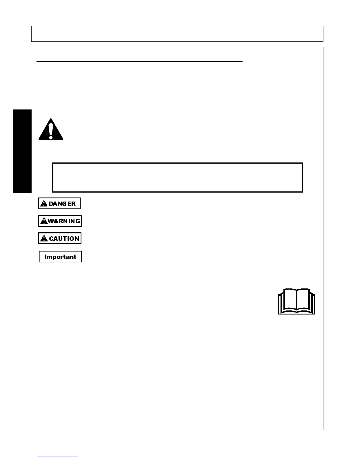
The Safety Alert Symbol combined with a Signal Word, as seen below, is used throughout this
manual and on decals which are attached to the equipment. The Safety Alert Symbol means:
“ATTENTION! BECOME ALERT! YOUR SAFETY IS INVOLVED!” The Symbol and Signal Word
are intended to warn the owner/operator of impending hazards and the degree of possible injury
faced when operating this equipment.
Indicates an imminently hazardous situation that, if not avoided, WILL result in DEATH OR
VERY SERIOUS INJURY.
Indicates an imminently hazardo us situation that, if not avoided, COULD result in DEATH
OR SERIOUS INJURY.
Indicates an imminently hazardous situation that, if not avoided, MAY result in MINOR
INJURY.
Identifies special instructions or procedures that, if not strictly observed, could result in
damage to, or destruction of the machine, attachments or the environment.
NOTE: Identifies points of particular interest for more efficient and convenient opera tio n or repair.
READ, UNDERSTAND, and FOLLOW the following Safety Messages. Serious injury or
death may occur unless care is taken to follow the warnings and instructions stated in this
Manual and in the Safety Messages on the implement. Always follow the instruction in this
manual and use good common sense to avoid hazards.
NOTE: If you want a translation of this safety section in one of the following Languages, please contact:
Translations at 1502 E. Walnut Street Seguin, TX 78155; Fax: (830) 372-9529; Safety Section Translations
are available in Spanish, Portuguese, French, German, Russian.
PN GS01
Practice all usual and customary safe working precautions and above all--remember safety is up to YOU
. Only YOU can prevent serious injury or death
from unsafe practices.
GENERAL SAFETY INSTRUCTIONS AND PRACTICES
SAFETY
RD5-RD6 05/12 Safety Section 1-2
© 2012 Alamo Group Inc.
Page 11
OPERATOR SAFETY
TO AVOID SERIOUS INJURY OR DEATH DO THE FOLLOWING:
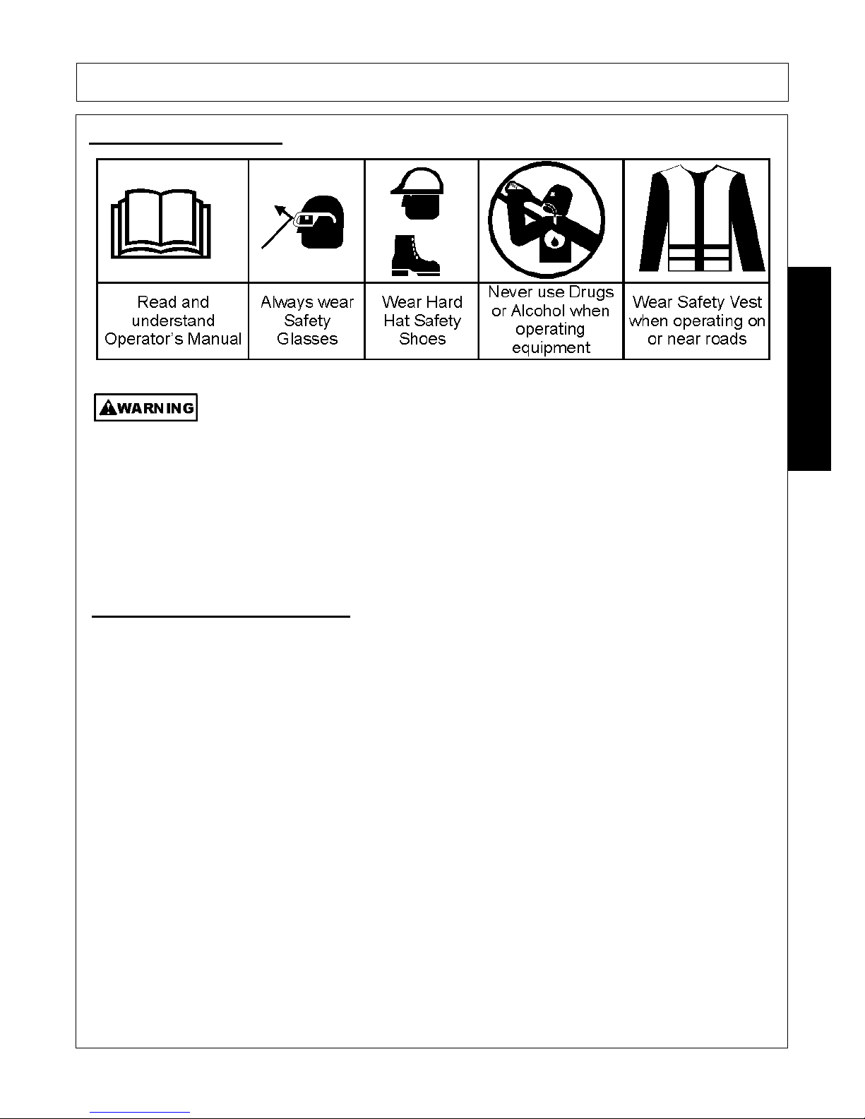
• READ, UNDERSTAND and FOLLOW Operator's Manual instructions, Warnings and Safety Messages.
• WEAR SAFETY GLASSES, safety shoes, hard hat, hearing protection and gloves when operating or
repairing equipment
• WEAR appropriate breathing respira tor whe n oper ating in dusty co ndition s to av oid r espirator y diseases.
• DO NOT WEAR loose clothing or jewelry to avoid rotating parts entanglement injury.
• DO NOT USE DRUGS or ALCOHOL before or while oper ating equipment.
• DO NOT ALLOW anyone to operate equipment under the influence of drug or alcohol.
• CONSULT medical professional for medication impairment side effects.
• STAY ALERT, prolonged operation can cause fatigue, STOP and REST.
GENERAL OPERATING SAFETY
VISIBILITY CONDITIONS WHEN MOWING:
• OPERATE IN DAYLIGHT or with lights that gives at least 100 yards clear visibility.
• BE ABLE TO SEE and identify passersby, steep slopes, ditches, drop-offs, overhead obstructions, power
lines, debris and foreign objects.
GROUND SPEED WHEN MOWING:
• NORMAL SPEED range is between 2 to 5mph.
• ADJUST MOWING SPEED for terrain conditions and grass type, density and cut height.
• REDUCE MOWING SPEED when near steep slopes, ditches, drop-offs, overhead obstructions, power
lines and to avoid debris and foreign objects.
INSECT INFESTATION
• Do Not operate in areas where bees or insects may attack unless you WEAR PROTECTIVE CLOTHING
or use enclosed tractor cab.
PTO SPEED:
• DO NOT EXCEED IMPLEMENT RATED PTO SPEED
• AVOID exceeding rated PTO speeds that may result in broken drivelines or blade failures.
SAFETY SIGNS:
• REPLACE missing, damaged or unreadable safety signs immediately.
PN OS01
SAFETY
SAFETY
RD5-RD6 05/12 Safety Section 1-3
© 2012 Alamo Group Inc.
Page 12

SAFETY
TO AVOID SERIOUS INJURY OR DEATH FROM BEING CRUSHED BY TRACTOR OR
IMPLEMENT:
WHEN BACKING
tractor to implement hitch:
• DO NOT ALLOW BYSTANDERS between tractor and implement
BEFORE connecting and disconnecting implement hitch:
• STOP TRACTOR ENGINE, place transmission into park, engage parking brake and remove key.
WHEN
connecting and disconnecting implement hitch:
• DO NOT crawl or walk under raised mower or wing.
• USE tongue JACK to lift heavy implement tongues to control implement tongue movement.
• AVOID overloading jack to prevent jack failure and injury.
WHEN CONNECTING IMPLEMENT DRIVELINE:
TO AVOID
implement driveline coming loose during operation:
• LUBRICATE yoke spring locking collar to ensure it freely slides on PTO shaft
• SECURELY seat yoke locking balls in PTO shaft groove.
• PUSH and PULL DRIVELINE on both the tractor and implement PTO SHAFTS to ensure it is SECURELY
ATTACHED
TO AVOID
broken driveline during operations:
• CHECK driveline for proper length between PTO shaft and implement gearbox shaft.
• Drivelines too short can pull apart or disengage.
• Drivelines too long can bottom out.
• Bottoming driveline telescoping assembly will stop sliding and become solid.
• Driveline bottoming can push through support bearings and break off PTO shaft.
CONTACT DEALER
if implement driveline does not match Tractor PTO shaft:
• DO NOT USE PTO ADAPTER.
Using a PTO adapter can cause:
• Excessive vibration, thrown objects, blade and implement failures by doubling operating speed.
• Increased working length exposing unshiel ded driveline areas and entanglement hazards.
DO NOT connect the Mower to a tractor with the PTO directly connected to the Tractor transmission. PN CD02
CONNECTION OR DISCONNECTING IMPLEMENT SAFETY
SAFETY
RD5-RD6 05/12 Safety Section 1-4
© 2012 Alamo Group Inc.
Page 13
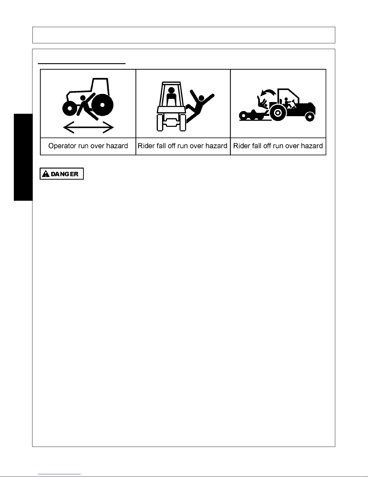
CRUSHING HAZARDS
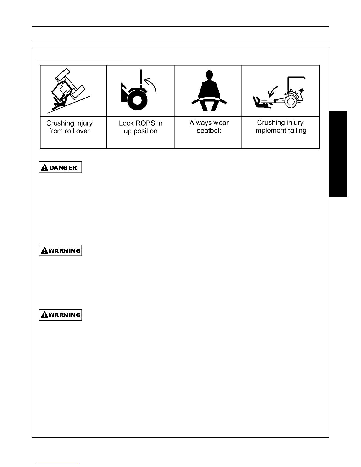
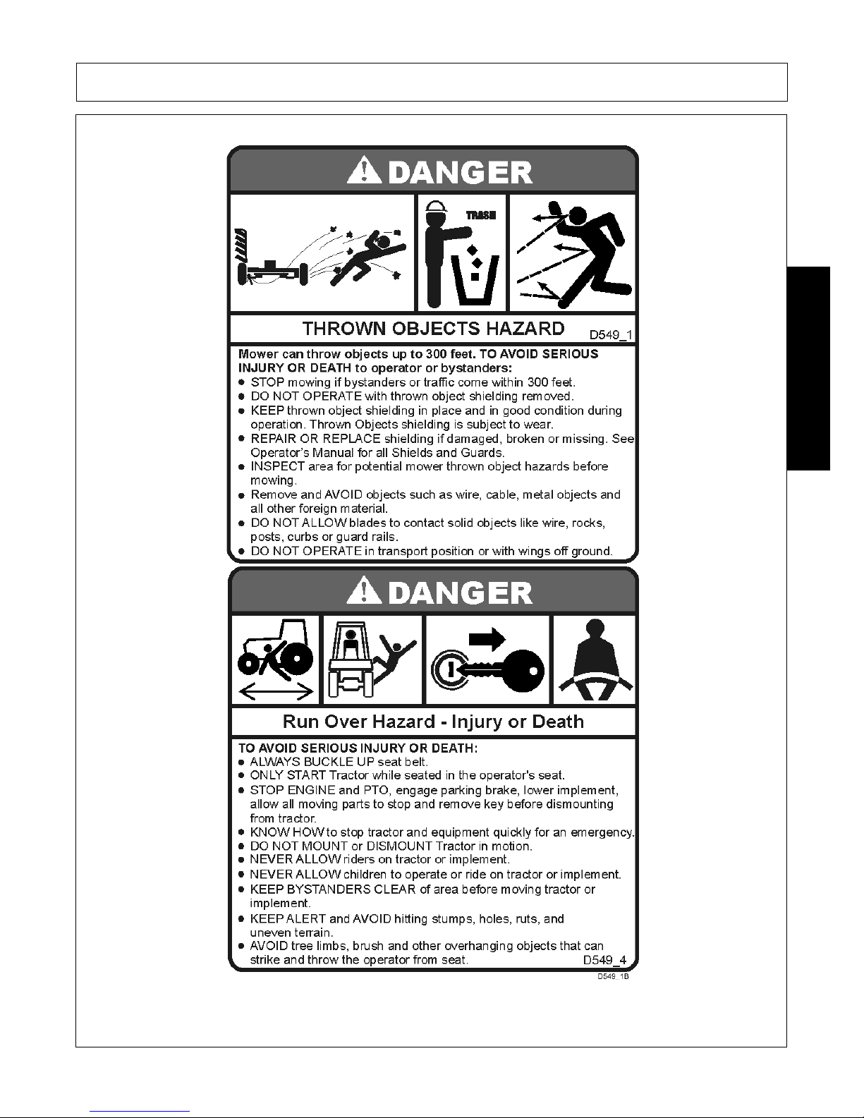
TO AVOID SERIOUS INJURY OR DEATH FROM FALLING OFF TRACTOR, EQUIPMENT RUN OVER,
ROLLOVER AND CRUSHING BY FALLING WING OR IMPLEMENT:
• USE ROPS and SEAT BELT equipped tractors for mowing operations.
• KEEP ROPS lock in up position.
• ALWAYS BUCKLE UP seat belt when operating tractor and equipment.
• ONLY OPERATE tractor and equipment while seated in tractor seat.
WHEN RAISING OR LOWERING IMPLEMENT:
•Raise or lower ONLY WHILE SEATED in tractor seat with seat belt buckled.
•Raise or lower ONLY when implement tongue is securely attached to tractor drawbar TO AVOID implement tip over.
• KEEP BYSTANDERS CLEAR of area TO AVOID crushing.
LIFTED Equipment can fall from mechanical or hydraulic failure or inadvertent Control Lever movement.
TO AVOID EQUIPMENT FALLING while working near or under lifted wings, components and
implements raised by 3-Pointed tractor hitch:
• SECURELY SUPPORT or block up raised equipment and components.
• BLOCK UP and securely support equipment before putting hands, feet or body under raised equipment or lifted components.
WHEN PARKING Implement and Tractor:
• LOWER implement, LOCK or BLOCK lifted parts before leaving equipment.
• NEVER leave implement unattended in a raised position.
TO AVOID CHILDREN FALLING OFF OR BEING CRUSHED BY EQUIPMENT:
• NEVER ALLOW children to play on or around Tractor or Implement.
WHEN UNHITCHING IMPLEMENT:
• LOWER implement, LOCK or BLOCK lifted parts before leaving equipment.
• USE tongue jack to control implement tongue movement.
• USE tongue JACK to lift heavy implement tongues.
• AVOID overloading jack to prevent jack failure and injury.
PN CH02
SAFETY
SAFETY
RD5-RD6 05/12 Safety Section 1-5
© 2012 Alamo Group Inc.
Page 14

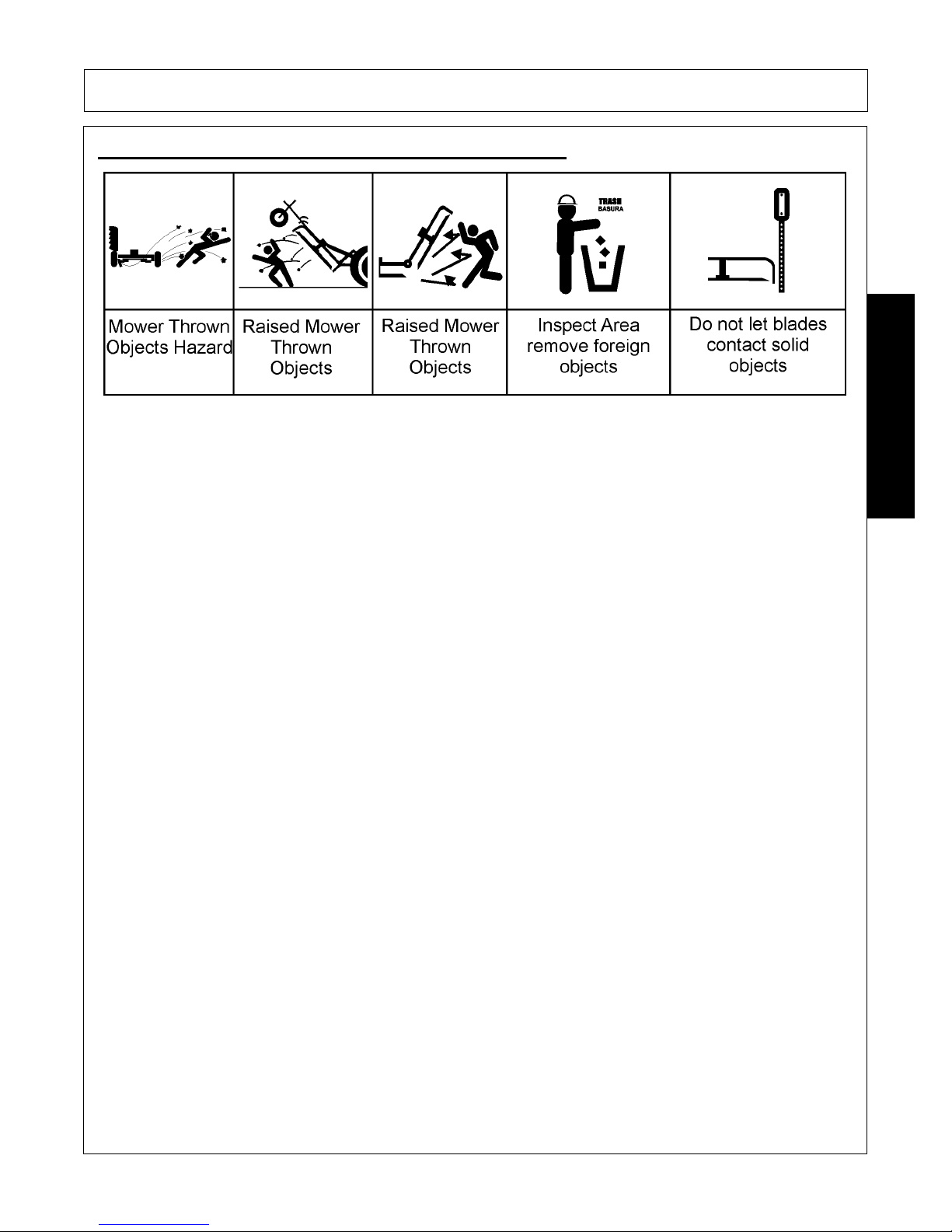
THROWN OBJECT HAZARDS
ROTARY MOWERS CAN THROW OBJECTS 300 FEET OR MORE UNDER ADVERSE
CONDITIONS.
TO AVOID SERIOUS INJURY OR DEATH TO OPERATOR OR BYSTANDERS FROM THROWN OBJECTS:
• KEEP bystanders 300 feet away
STOP MOWING IF PASSERSBY ARE WITHIN 300 FEET UNLESS:
• All THROWN OBJECT SHIELDING including, Front and Rear Deflectors, Chains Guards, Steel Guards, Bands,
Side Skirts and Skid Shoes in place and in good condition when mowing.
• Mower sections or wing are adjusted to be close and parallel to ground without exposing blades.
• MOWING AREA has been inspected and foreign materials an d debris have been removed.
• PASSERSBY are inside enclosed vehicle.
INSPECT AREA FOR POTENTIAL THROWN OBJECTS BEFORE MOWING:
• REMOVE debris, rocks, wire, cable, metal objects and other foreign material from area.
Wire, cable, rope, chains and metal objects can be thrown or swing outside deck with great velocity:
1. MARK objects that cannot removed.
2. AVOID these objects when mowing.
HIGH GRASS and WEED AREA INSPECTION:
• INSPECT for and REMOVE any hidden large debris.
• MOW at Intermediate height
• INSPECT and remove remaining debris
• MOW at final height.
MOWER THROWN OBJECT SHIELDING:
• KEEP all thrown object shielding including, Front an d Rear Deflectors, Chains Guards, Steel Guards, Bands, Side
Skirts and Skid Shoes in place and in good condition when mowing.
• DO NOT OPERATE with any thrown object shielding missing, damaged or removed.
RIGHT OF WAY (Highway) MOWING
• USE DOUBLE CHAIN GUARDS for highway, right-of-way, parks or greenbelt mowing or all other mowing where
human dwellings, vehicles, or livestock could be within 300 feet of the mower.
• No shielding is 100% effective in preventing thrown objects. To Reduce Possibility of Injury:
1. MAINT A IN MOW ER SHIELDING, side skirts, skid shoes, and blades in good operational condition,
2. RAISE CUTTING HEIGHT to 6 INCHES minimum,
3. INSPECT AREA thoroughly before mowing to REMOVE potential THROWN OBJECT HAZARDS,
4. NEVER ALLOW BLADES to CONTACT SOLID OBJECTS like wire, rocks, post, curbs, guardrails, or ground
while mowing.
PN TO02
SAFETY
SAFETY
RD5-RD6 05/12 Safety Section 1-6
© 2012 Alamo Group Inc.
Page 15
SAFETY
MOWER OPERATION:
• DO NOT exceed mower's rated Cutting Capacity or cut non-vegetative material.
• USE ENCLOSED TRACTOR CABS when two or more mowers are operating in mowing area.
• Do Not mow in areas where bees or insect s may att a ck unles s yo u WEAR PROTECTIVE CLOTHING or
use enclosed tractor cab.
• ADJUST mower sections or wing close and parallel to ground without exposing blades.
• ADJUST cutting HEIGHT to AVOID BLADE CONTACT with solid objects like wire, rocks, posts, curbs,
guard rails and fixed obstructions.
• DO NOT operate mower when mower wing(s) is raised or in transport position.
• STOP MOWING immediately if blades strike heavy objects, fixed structures, metal guard rails and con-
crete structures:
1. BLADES CAN FAIL from impact and objects can be thrown with great velocity.
2. INSPECT and REPLACE any damaged blades.
3. CHECK blade carrier and REPLACE if damaged.
• DO NOT mow in standing water TO AVOID possible BLADE FAILURE.
• AVOID MOWING in reverse:
1. STOP PTO and back up mower.
2. LOWER mower, engage PTO and mow forward.
• STOP PTO and BLADES when raising wings or the mower to transport position.
• DO NOT ENGAGE PTO with mower in transport position.
• STOP mowing when EXCESSIVE VIBRATION occurs:
1. STOP PTO and tractor ENGINE.
2. INSPECT mower for vibration source.
3. REPLACE any damage parts and bent or damaged BLADES.
PN TO01-X
THROWN OBJECTS HAZARDS (CONTINUED)
SAFETY
RD5-RD6 05/12 Safety Section 1-7
© 2012 Alamo Group Inc.
Page 16
RUN OVER HAZARDS
TO AVOID SERIOUS INJURY OR DEATH FROM FALLING OFF TRACTOR OR
EQUIPMENT RUN OVER:
• USE ROPS and SEAT BELT equipped tractors for mowing operations.
• KEEP ROPS locked in UP position.
• ONLY start tractor while seated in tractor seat.
• ALWAYS BUCKLE UP seat belt when operating tractor and equipment.
• ONLY OPERATE tractor and equipment while seated in tractor seat.
• NEVER ALLOW RIDERS on tractor or implement.
WHEN MOUNTING AND DISMOUNTING TRACTOR:
• ONLY mount or dismount when tractor and moving parts are stopped.
• STOP ENGINE AND PTO, engage parking brake, lower implement, allow all moving parts to stop
and remove key before dismounting from tractor.
PN RO01
SAFETY
SAFETY
RD5-RD6 05/12 Safety Section 1-8
© 2012 Alamo Group Inc.
Page 17

SAFETY
KEEP AWAY FROM ROTATING DRIVELINES AND ELEMENTS TO AVOID SERIOUS INJURY OR
DEATH:
STAY AWAY
and KEEP hands, feet and body AWAY from rotating blades, drivelines and parts until all moving
elements have stopped.
• STOP, LOOK and LISTEN before approaching the mower to make sure all rotating motion has stopped.
• ROTATING COMPONENTS CONTINUE to ROTATE after the PTO is shut off.
PTO SHIELDING:
TO AVOID SERIOUS INJURY OR DEATH FROM ENTANGLEMENT WHEN OPERATING IMPLEMENT:
• KEEP PTO shields, integral driveline shields and input shields installed
• DO NOT OPERATE mower without shields and guards in place or missing
• REPAIR OR REPLACE if damage, broken or missing
• ALWAYS REPLACE GUARDS that have been removed for service or maintenance.
• Do Not use PTO or PTO guard as a step.
TO AVOID
broken driveline during operations:
• CHECK driveline for proper length between PTO shaft and implement gearbox shaft.(Refer to Instructions in
Operation Section)
• Drivelines too short can pull apart or disengage.
• Drivelines too long can bottom out.
Bottoming driveline telescoping assembly will stop sliding and become solid.
• Driveline bottoming can push through support bearings and break off PTO shaft
• AVOID sharp turns or lift mower to heights to cause driveline "knocking".
• Lubricate driveshaft-telescoping components weekly.
CONTACT DEALER
if implement driveline does not match Tractor PTO shaft:
• DO NOT USE PTO ADAPTER.
Using a PTO adapter can cause excessive vibration, thrown objects, blade and implement failures by
doubling operating speed. Increased working length exposing unshielded driveline areas.
PN PE01
PTO ENTANGLEMENT HAZARDS
SAFETY
RD5-RD6 05/12 Safety Section 1-9
© 2012 Alamo Group Inc.
Page 18
SAFETY
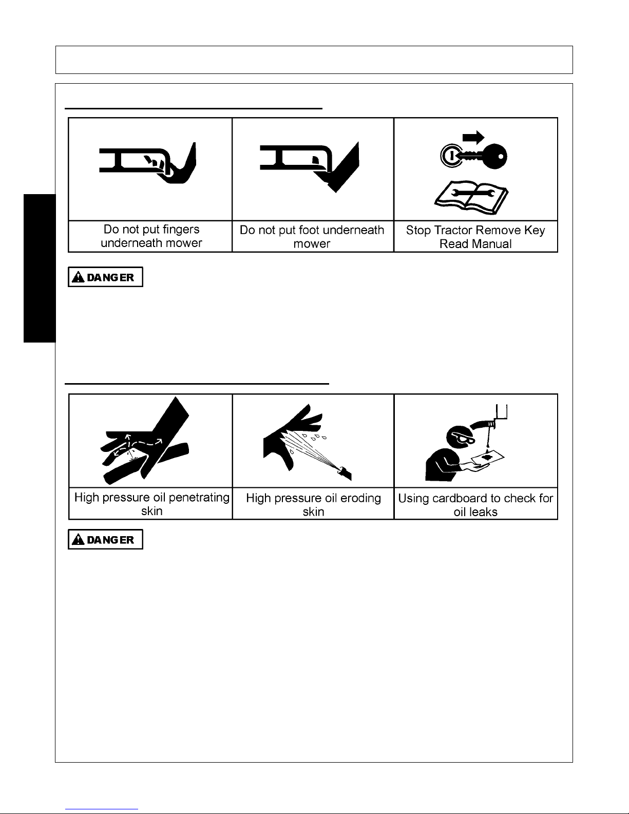
KEEP AWAY FROM ROTATING BLADES TO AVOID SERIOUS INJURY OR DEATH FROM
BLADE CONTACT:
• STAY AWAY and KEEP HANDS, FEET and BODY AWAY from rotating blades, drivelines and parts until all moving
elements have stopped.
• DO NOT put hands or feet under mower decks
• STOP rotating BLADES disengage PTO and wait for blade to stop rotating before raising mower deck or wings
• STOP LOOK and LISTEN before approaching the mower to make sure all rotating motion has stopped.
PN MB01
TO AVOID SERIOUS INJURY OR DEATH FROM HIGH PRESSURE HYDRAULIC OIL LEAKS
PENERA T ING SKIN:
• DO NOT OPERATE equipment with oil or fuel leaks.
• KEEP all hydraulic hoses, lines and connections in GOOD CONDITION and TIGHT before applying system
pressure.
• RELIEVE HYDRAULIC PRESSURE before disconnecting lines or working on the system.
• REMOVE and replace hose if you suspect it leaks. Have dealer test it for leaks.
HIGH PRESSURE FLUID LEAKS CAN BE INVISIBLE.
WHEN CHECKING FOR HYDRAULIC LEAKS AND WORKING AROUND HYDRAULIC SYSTEMS:
• ALWAYS WEAR safety glasses and impenetrable gloves.
• USE paper or cardboard to search for leaks.
• DO NOT USE hands or body parts to search for leak.
• KEEP hands and body AWAY from pin holes and nozzles ejecting hydrau lic fluid.
• Hydraulic fluid may cause gangrene if not surgically removed immediately by a doctor familiar with this form of injury.
PN HP01
MOWER BLADE CONTACT HAZARDS
SAFETY
HIGH PRESSURE OIL LEAK HAZARDS
RD5-RD6 05/12 Safety Section 1-10
© 2012 Alamo Group Inc.
Page 19
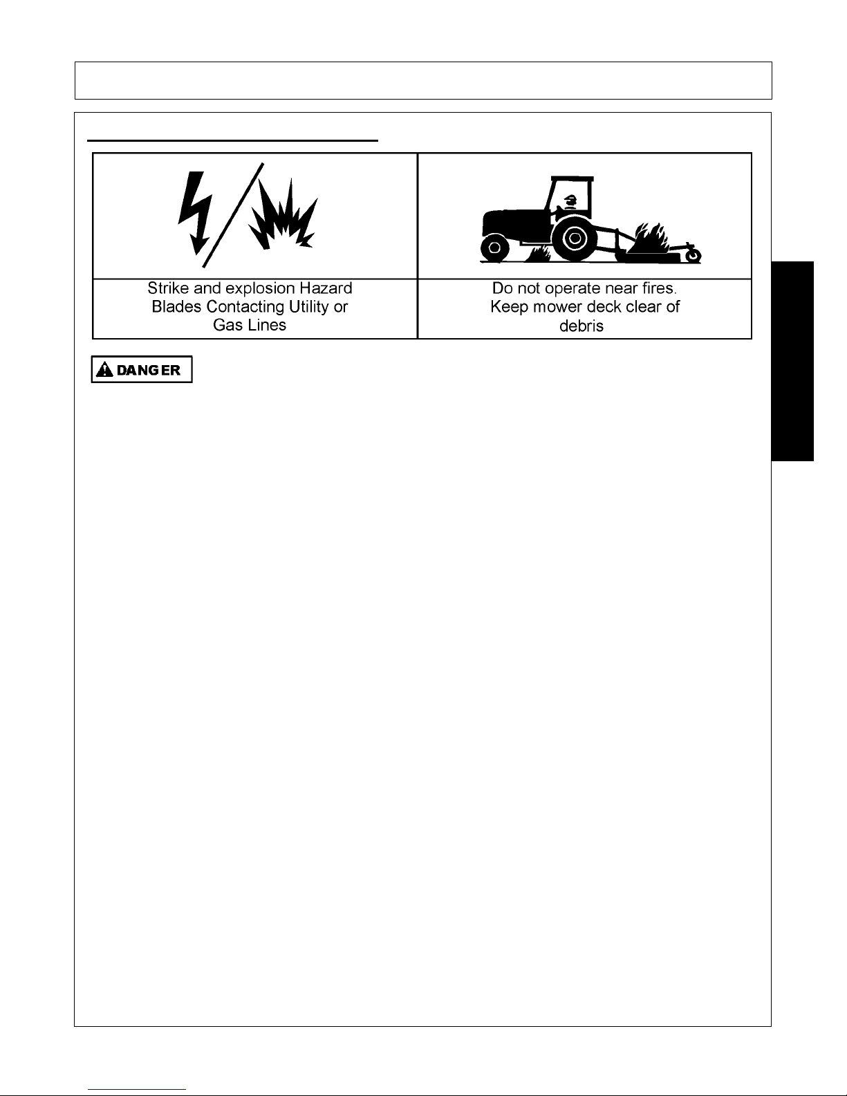
SAFETY
TO AVOID SERIOUS INJURY OR DEATH FROM ELECTRICAL CONTACT WHEN
WORKING AROUND ELECTRICAL POWER LINES, GAS LINES AND UTILITY LINES:
• INSPECT mowing area for overhead or underground electrical power lines, obstructions, gas lines,
cables and Utility , Municipal, or other type structure.
• DO NOT allow mower to contact with any Utility, Municipal, or type of structures and obstructions.
• CALL 811 and 1-800-258-0808 for identify buried utility lines.
FIRE PREVENTION GUIDELINES while Operating, Servicing, and Repairing Mower and Tractor to
reduce equipment and grass fire Risk:
• EQUIP Tractor with a FIRE EXTINGUISHER
• DO NOT OPERATE mower on a tractor equipped with under frame exhaust
• DO NOT SMOKE or have open flame near Mower or Tractor
• DO NOT DRIVE into burning debris or freshly burnt area
• AVOID FIRE IGNITION by not allowing mower blade to contact solid objects like metal or rock.
• ADJUST SLIP CLUTCHES to avoid excessive slippage and clutch plate heating.
• CLEAR any grass clippings or debris buildup around mower drivelines, slip clutches, and gearboxes.
• SHUT OFF ENGINE while refueling.
PN EF02
ELECTRICAL & FIRE HAZARDS
SAFETY
RD5-RD6 05/12 Safety Section 1-11
© 2012 Alamo Group Inc.
Page 20

TRANSPORTING HAZARDS
TO AVOID SERIOUS INJURY AND DEATH WHEN TOWING OR TRANSPORTING EQUIPMENT:
• KEEP transport speed BELOW 20 mph to maintain control of equipment.
• REDUCE SPEED on inclines, on turns and in poor towing conditions .
• DO NOT TOW with trucks or other vehicles
• USE only properly sized and equipped tractor for towing equipment.
• FOLLOW all local traffic regulations.
TRACTOR REQUIREMENTS FOR TOWING OR TRANSPORTING IMPLEMENTS:
• ONLY TRANSPORT with tractor with ROPS in the raised position.
• USE properly sized and equipped tractor that exceeds implement weight by at least 20%
• KEEP 20% of tractor weight on front wheels to maintain safe steering.
BEFORE TRANSPORTING OR TOWING IMPLEMENT:
TRACTOR INSPECTION:
• CHECK steering and braking for proper operation and in good condition.
• CHECK SMV sign, reflectors and warning lights for proper operation and visibility behind unit.
• CHECK that your driving vision is not impaired by tractor, cab, or implement while seated in tractor seat.
• ADJUST your operating position, mirrors, and implement transport for clear vision for traveling and traffic conditions.
PREPARE IMPLEMENT FOR TRANSPORTING OR TOWING:
• DISENGAGE PTO
• RAISE MOWER
• REMOVE any cut material collected on mower deck.
TOWED MOWERS - ENGAGE TRANSPORT LOCKS AND SAFETY CHAINS:
• INSTALL center axle cylinder transport stops or pins
• ATTACH implement SAFETY CHAIN to tractor
DETERMINE STOPPING CHARACTERISTICS OF TRACTOR AND IMPLEMENT FOR TRANSPORTING OR
TOWING:
BRAKING TESTS:
• APPLY brakes at increasing speeds
• Observe STOPPING distances increases with increased speeds.
• DETERMINE the maximum safe transport speed that does not exceed 20 mph
DETERMINE MAXIMUM TURNING SPEED BEFORE OPERA T ING ON ROADS OR UNEVEN GROUND:
• TEST equipment in slowly increasing speed in turns to determine it can be operated at higher speeds.
• USE REDUCED turning speeds in sharp turns to avoid equipment turn ing over.
WHEN TOWING OR TRANSPORTING EQUIPMENT:
• Always WEAR SEAT BELT when operating or transporting mower.
• USE low speeds to avoid overturn with raised wings.
• USE low speeds and gradual steering on curves, hills, rough or uneven surfaces and on wet roads
• TURN ON tractor FLASHING WARNING LIGHTS.
• ALLOW cle
a
rance for implement swing while turning. PN TH02
SAFETY
SAFETY
RD5-RD6 05/12 Safety Section 1-12
© 2012 Alamo Group Inc.
Page 21
SAFETY
AVOID SERIOUS INJURY OR DEATH FROM COMPONENT FAILURE BY KEEPING IMPLEMENT IN
GOOD OPERATING CONDITION IN PERFORMING PROPER SERVICE, REPAIRS AND
MAINTENANCE.
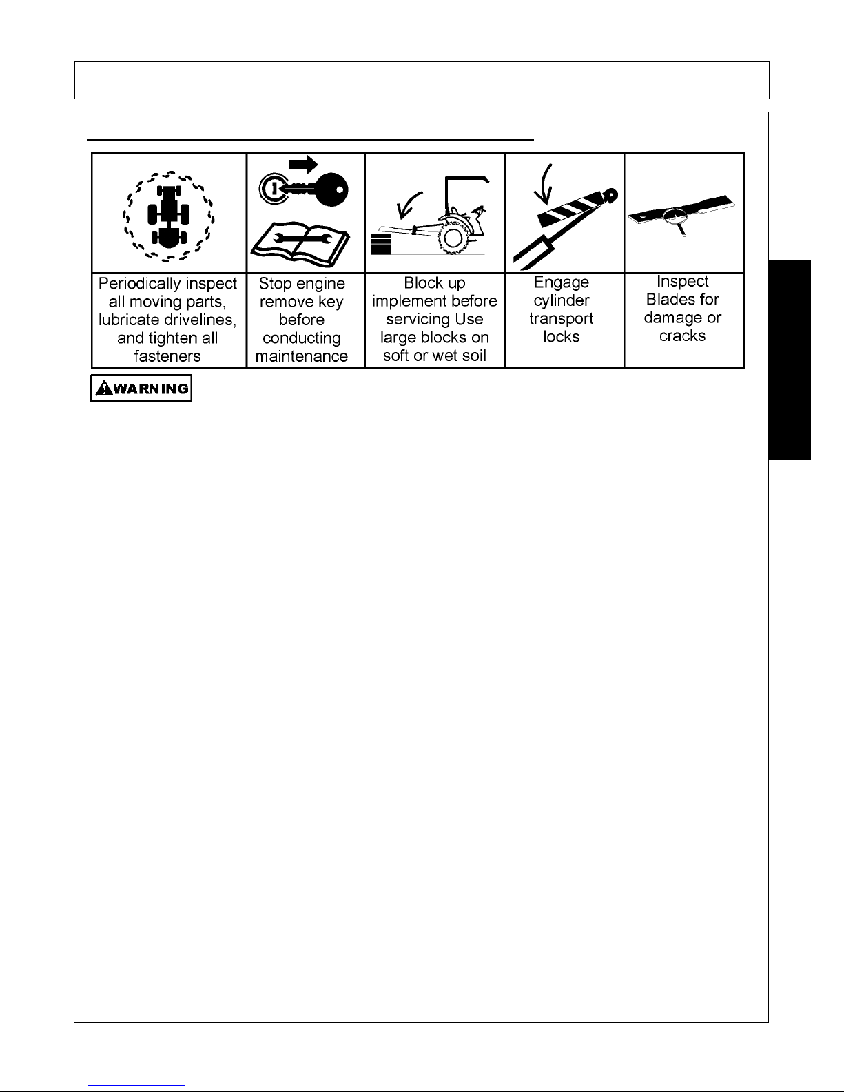
BEFORE PERFORMING SERVICE, REPAIRS AND MAINTENANCE ON THE IMPLEMENT:
• STOP ENGINE AND PTO, engage parking brake, lower implement, allow all moving parts to stop and remove key before
dismounting from tractor.
• PLACE implement on ground or securely block up raised equipment. Use large blocks on soft or wet soil.
• PUSH and PULL Remote Hydraulic Cylinder lever to relieve hydraulic pressure.
• DISCONNECT IMPLEMENT driveline from tractor PTO SHAFT.
WEAR SAFETY GLASSES, P ROTECTIVE GLOVES and follow SAFETY PROCEDURES when performing service, repairs
and maintenance on the implement:
• Always WEAR protective GLOVES when handling blades, knives, cutting edges or worn component with sharp edges.
• Always WEAR GLOVES and SAFETY GLASSES when servicing hot components
• AVOID CONTACT with hot hydraulic oil tanks, pumps, motors, valves and hose connection surfaces.
• SECURE LY support or BLOCK UP raised implement, framework and lifted components before working underneath
equipment.
• STOP any implement movements and SHUT-OFF TRACTOR engine before doing any work procedures.
• USE ladder or raised stands to reach high equipment areas inaccessible from ground.
• ENSURE good footing by standing on solid flat surfaces when getting on implement to perform work.
• FOLLOW manufacturer's instructions in handling oils, solvents, cleansers, and other chemical agents.
• DO NOT change any factory-set hydraulic calibrations to avoid component or equipment failures.
• DO NOT modify or alter implement, functions or components.
• DO NO T WELD or repair rotating mower components. These may cause vibrations and component failures being thrown
from mower.
PERFORM SERVICE, REPAIRS, LUBRICATION AND MAINTENANCE OUTLINED IN IMPLEMENT MAINTENANCE
SECTION:
• INSPECT for loose fasteners, worn or broken parts, leaky or loose fittings, missing or broken cotter keys and washers on
pins, and all moving parts for wear.
• REPLACE any worn or broken parts with authorized service parts.
• LUBRICATE unit as specified by lubrication schedule
• NEVER lubricate, adjust or remove material while it is running or in motion.
• TORQUE all bolts and nuts as specified.
BLADE INSPECTION:
• REPLACE bent, damage, cracked or broken blades immediately with new blades.
• AVOID blade failures and thrown broken blades. DO NOT straighten, weld, or weld hard-facing blades.
SAFETY SHIELDS, GUARDS AND SAFETY DEVICES INSPECTION:
• KEEP
all Deflectors, Chain Guards, Steel Guards, Gearbox Shields, an
d PT
O integral shields, Bands, Side Skirts and Skid
Shoes in place and in good condition.
• REPLACE any missing, broken or worn safety shields, guards and safety devices.
• Engine Exhaust, some of its constituents, and certain vehicle components contain or emit chemicals known to the state of
California to cause cancer, birth defects or other reproductive harm.
• Battery posts, terminals and related accessories contain lead and lead compounds, chemicals known to the state of
California to cause cancer, birth defects or other reproductive harm.
PN HM01
HAZARDS WITH MAINTENANCE OF IMPLEMENT
SAFETY
RD5-RD6 05/12 Safety Section 1-13
© 2012 Alamo Group Inc.
Page 22

PARTS INFORMATION
PARTS INFORMATION
Bush Hog mowers use balanced and matched system components for blade carriers, blades, cuttershafts,
knives, knife hangers, rollers, drivetrain components, and be arings. These pa rt s a re made an d tested to Bush
Hog specifications. Non-genuine "will fit" parts do not consistently meet these specifications. The use of “will
fit” parts may reduce mower performance , void warranties, and present a safety ha zard. Use genuine Bus h
Hog mower parts for economy and safety.
(SPBH-1)
SEE YOUR BUSH HOG DEALER
SAFETY
SAFETY
RD5-RD6 05/12 Safety Section 1-14
© 2012 Alamo Group Inc.
Page 23

SAFETY
Decal Location
NOTE: Bush Hog supplies safety decals on this product to promote safe operation. Damage to the decals may
occur while in shipping, use, or recondition ing. Bush Hog cares about the safety of its customers, operators,
and bystanders, and will replace the safety decals on this product in the field, free of charge (Some shipping
and handling charges may apply). Contact your Bush Hog dealer to order replacement decals.
SAFETY
RD5-RD6 05/12 Safety Section 1-15
© 2012 Alamo Group Inc.
Page 24

SAFETY
ITEM PART NO. QTY TYPE DESCRIPTION
1. D395 1 WARNING Blade Attachment
2. D572 1 DANGER Shear Bolt Length
3. D590 1 INSTRUCT Lubrication Chart
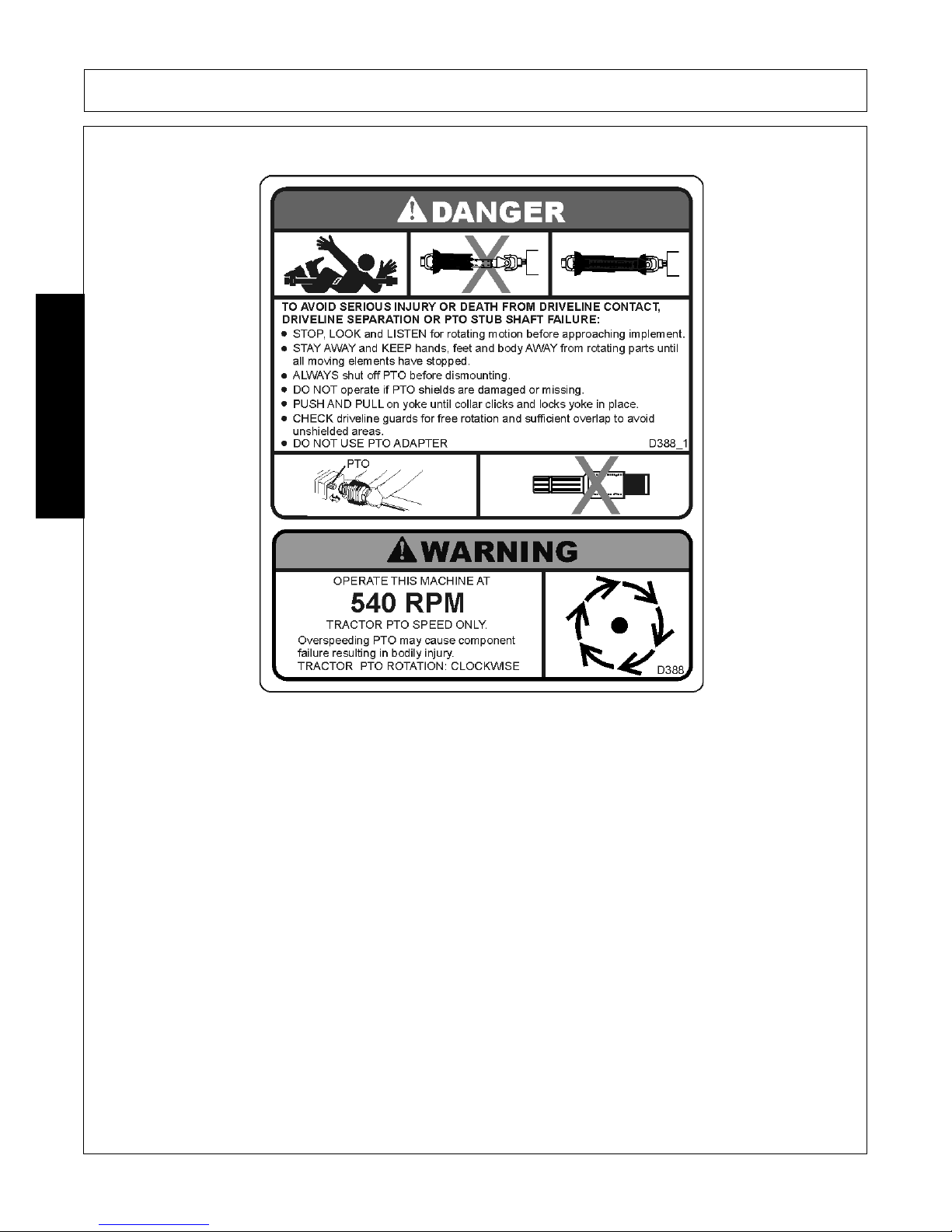
4. D388 1 DANGER Driveline Hazard
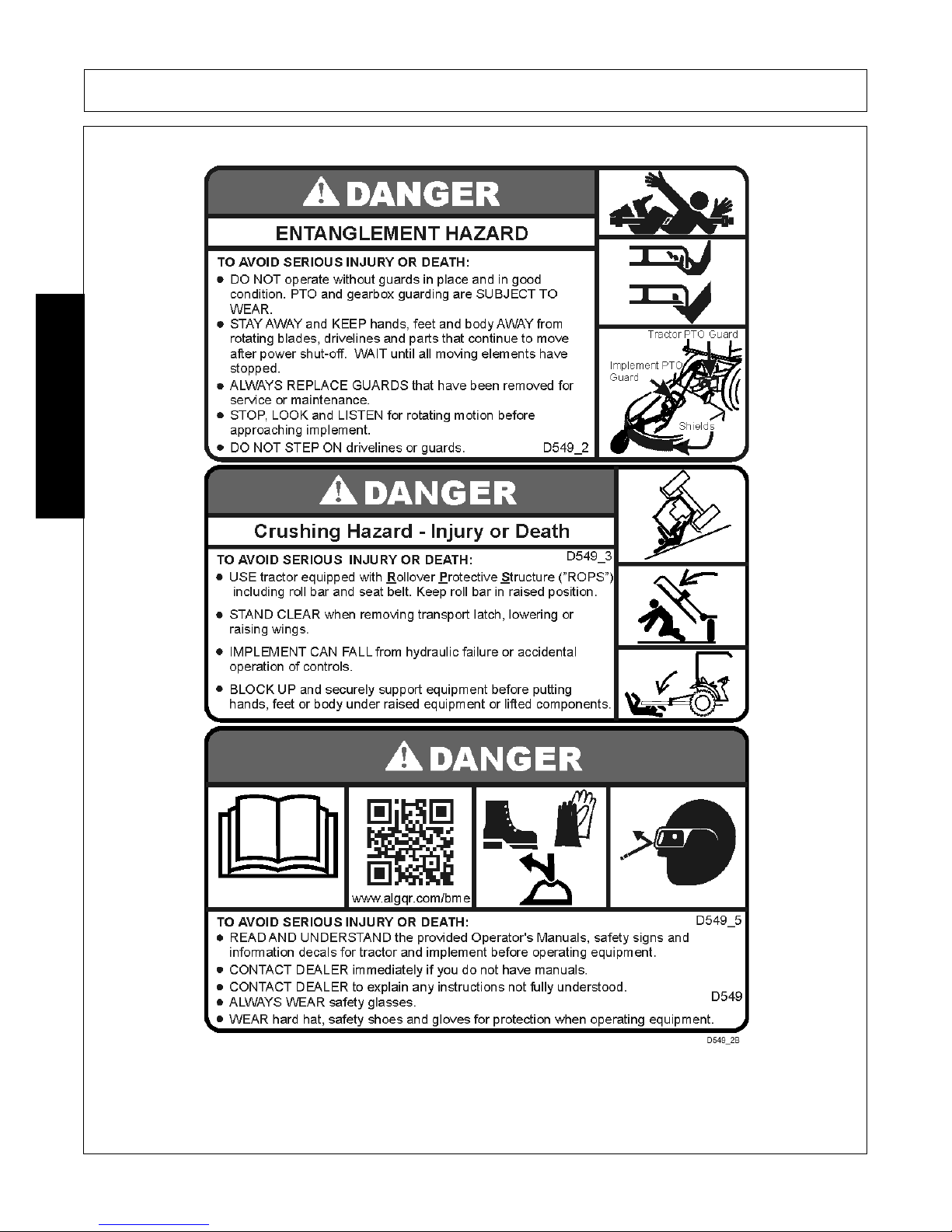
5. D549 1 DANGER General Multi-Hazard
6. D559 1 WARNING Genuine Parts
7. 50054672 2 LOGO Bush Hog Logo
8. 50068911 1 LOGO RD5 Model
50068912 1 LOGO RD6 Model
9. 2738332 2 REFLECT Red Reflectors
10. NFS 1 SER PLT Serial Number Plate
SAFETY
11. 00756004 1 DANGER Shield Missing
12. 03200347 1 REFLECT SMV
13. 50035829 1 ________ Canister, Operator’s Manual Inside
14. 50068908C 1 ________ Operator’s Manual
15. D137 1 IMPORTANT CCW Rotation
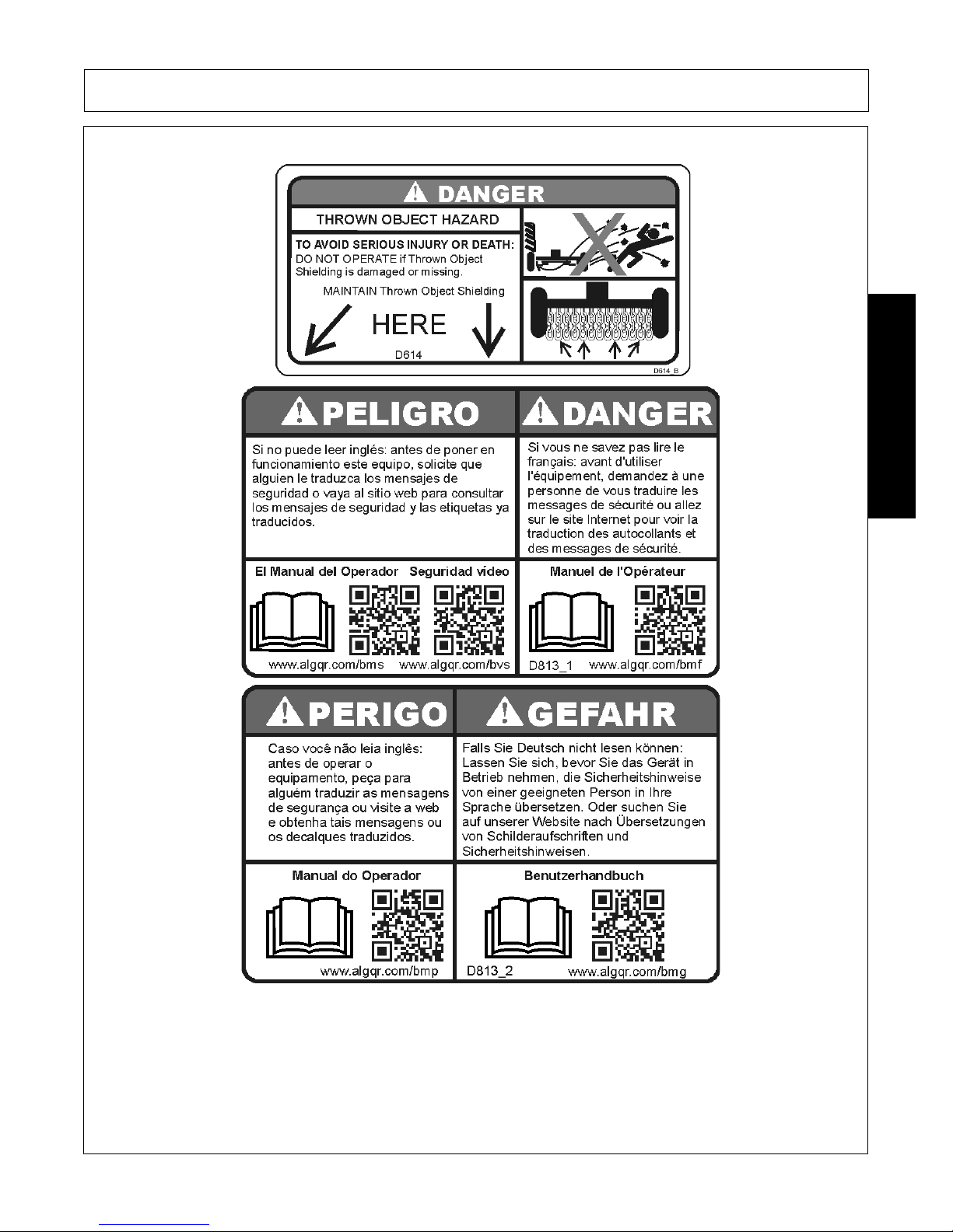
16. D614 2 DANGER Thrown Object Shield Missing
17. D813 1 DANGER Multi-Language
18. D454 1 WARNING Crushing Hazard (Decal Under Deck)
19. 00756005 1* DANGER Rotating Driveline (Not Shown)
** Furnished by Driveline Manufacturer
Decal Sheets
Liability Sheet - 00781352
Logo Sheet RD5 - 00787356
Logo Sheet RD6 - 00787357
RD5-RD6 05/12 Safety Section 1-16
© 2012 Alamo Group Inc.
Page 25
Decal Description
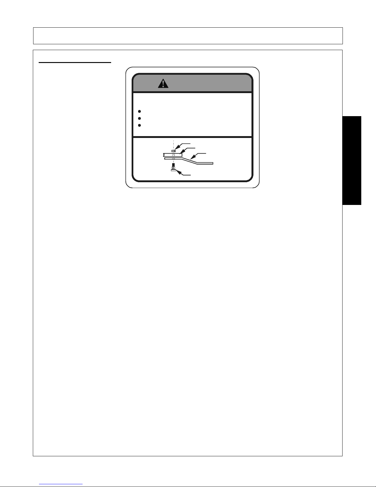
WARNING
FROM BLADE A TTACHMENT FAILURE:
ALWAYS replace blades in pa irs.
A
and nuts.
SAFETY
TO AVOID SERIOUS INJURY OR DEATH
Torque blade bolt to 300 ft lbs.
LWAYS replace blades with new bolts
SAFETY
Blade N ut
Blade P an
Blade
Blade B olt
D395
RD5-RD6 05/12 Safety Section 1-17
© 2012 Alamo Group Inc.
Page 26
SAFETY
SAFETY
RD5-RD6 05/12 Safety Section 1-18
© 2012 Alamo Group Inc.
Page 27
SAFETY
SAFETY
RD5-RD6 05/12 Safety Section 1-19
© 2012 Alamo Group Inc.
Page 28
SAFETY
SAFETY
RD5-RD6 05/12 Safety Section 1-20
© 2012 Alamo Group Inc.
Page 29
SAFETY
SAFETY
RD5-RD6 05/12 Safety Section 1-21
© 2012 Alamo Group Inc.
Page 30

SAFETY
SAFETY
RD5-RD6 05/12 Safety Section 1-22
© 2012 Alamo Group Inc.
Page 31

SAFETY
Federal Laws and Regulations
This section is intended to explain in broad terms the concept and effect of federal laws and regulations concerning
employer and employee equipment operators. This section is not intended as a legal interpretation of the law and
should not be considered as such.
Employer-Employee Operator Regulations
U.S. Public Law 91-596 (The Williams-Steiger Occupational and Health Act of 1970) OSHA
This Act Seeks:
“...to assure so far as possible every working man and woman in the nation safe and healthful working
conditions and to preserve our human resources...”
DUTIES
Sec. 5 (a) Each employer(1) shall furnish to each of his employees employment and a place of employment which are free from
recognized hazards that are causing or are likely to cause death or serious physical harm to his employees;
(2) shall comply with occupational safety and health standards promulgated under this Act.
(b) Each employee shall comply with occupational safety and health standards and all rules, regulations and
orders issued pursuant to this Act which are applicable to his own actions and conduct.
OSHA Training Requirements
Title 29, Code of Federal Regulations Part 1928.57(a)(6). www.osha.gov
Operator instructions. At the time of initial assignment and at least annually thereafter, the employer shall
instruct every employee who operates an agricultural tractor and implements in the safe operating practices
and servicing of equipment with which they are or will be involved, and of any othe r practices dictated by the
work environment.
Keep all guards in place when the machine is in operation;
Permit no riders on equipment
Stop engine, disconnect the power source, and wait for all machine movement to stop before servicing,
adjusting, cleaning or unclogging the equip ment, except where the machine must be running to be properly
serviced or maintained, in which case the employer shall instruct employees as to all steps and procedures
which are necessary to safely service or maintain the equipment.
Make sure everyone is clear of machinery before starting the engine, engaging power, or operating the
machine.
Employer Responsibilities:
To ensure employee safety during Tractor and Implement operation, it is the employer’s responsibility to:
1. Train the employee in the proper and safe operation of the Tractor and Implement.
2. Require that the employee read and fully understand the Tractor and Implement Operator’s manual.
3. Permit only qualified and properly trained employees to operate the Tractor and Implement.
4. Maintain the Tractor and Implement in a safe operational condition and maintain all shields and guards on the
equipment.
5. Ensure the Tractor is equipped with a functional ROPS and seat belt and require that the employee ope rator
securely fasten the safety belt and operate with the ROPS in the raised position at all times.
6. Forbid the employee operator to carry additional riders on the Tractor or Implement.
7. Provide the required tools to maintain the Tractor and Implement in a good safe working condition and provide the
necessary support devices to secure the equipment safely while performing repairs and service.
8. Require that the employee operator stop operation if bystanders or passersby come within 300 feet.
Child Labor Under 16 Y ear s of Age
Some regulations specify that no one under the age of 16 may ope rate power machinery. It is your responsibility to
know what these regulations are in your own area or situation. (Refer to U.S. Dept. of Labor, Employment Standard
Administration, Wage & Home Division, Child Labor Bulletin #102.)
RD5-RD6 05/12 Safety Section 1-23
© 2012 Alamo Group Inc.
SAFETY
Page 32

Page 33

INTRODUCTION SECTION
© 2012 Alamo Group Inc.
Introduction Section 2-1
Page 34

INTRODUCTION
We are pleased to have you as a Bush Hog customer. Your Rotary Cutter has been carefully designed with
care and built with quality materials by skilled workers to give maximum service with minimum down time. This
manual is provided to give you the necessary operating and maintenance instructions for keeping your rotary
cutter in top operating condition. Careful use and timely service saves extensive repairs and costly downtime
losses. Please read this manual thoroughly. Understand what each control is for and how to use it.
Bush Hog typically offers three types of shielding to pr otect the ope rator, passerby, livestock, and property from
thrown objects... deflectors, single chain guards, and double chain guar ds. Shielding should be selected based
on the intended use of the mower. Double chain guards or deflectors should be used for highway, right-of-way,
parks or greenbelt mowing or all other mowing where human dwellings, vehicles, or livestock could be within
300 feet of the mower. Chain guards are more durable, provide a longer service life and require less
maintenance and replacement than deflectors. Single chain guards may be sufficient for agriculture and other
mower use only where passersby or property are not within 300 feet of the mower during operation.
No shielding is 100% effective in preventing thrown objects. The possibility of injury and property damage from
this hazard can be substantially reduce by selecting proper shielding, maintaining the mower and shielding in
good operational condition, inspecting the area for foreign debris before mowing, operating the mower at a
minimum cutting height of 4", and keep unprotected persons at a minimum distance of 300 feet from the
INTRODUCTION
mower at all times during operation.
Safety is of primary importance to the owner/operator and to the manufacturer. Observe all safety precaution
decals on the machine and noted throughout the manual for safe operation of implement. If any assistance or
additional information is needed, contact your authorized Bush Hog dealer. The owner/operator/dealer should
know and understand the Safety Messages before assembly and be aware of the hazards of operating this
cutter during assembly, use, and maintenance. The Safety Al ert Symbol combined with a Signal Word, as seen
below, is intended to warn the owner/operator of impe nding hazards and the deg ree of possible injury faced
when operating this machine.
Indicates an imminently hazardous situation that, if not avoided, WILL result in DEATH OR
VERY SERIOUS INJURY.
Indicates an imminently hazardous situation that, if not avoided, COULD result in DEATH
OR SERIOUS INJURY.
Indicates an imminently hazardous situation that, if not avoided, MAY result in MINOR
INJURY.
Identifies special instructions or procedures that, if not strictly observed, could result in
damage to, or destruction of the machine, atta ch me nts or the en vir on m en t.
RD5-RD6 05/12 Introduction Section 2-2
© 2012 Alamo Group Inc.
Page 35

INTRODUCTION
INTRODUCTION
The Bush Hog RD5-RD6 Rotary Mower is designed for medium duty applications such as weed, grass, corn
stalks and light brush to 1” diameter. These mowers are single spindle with two free-swinging blades. Free
swinging blades reduce the shock of impact when a stationary object is hit. Additional protection is provided by
a shear bolt on the gearbox input shaft. These Mowers are attached to the tractor using 3-Point Cat I standard
hitch. Standard equipment includes driveline shields, clutch shields and front and rear discharge shields.
Equipment Specifications
RD5 RD6 RD5 RD6
Cutting Width 60” 72” Blade Tip Speed
Transport Width 66” 78” 12469 FPM 14963 FPM
Overall Width 66” 78”
Overall Length 88” 107”
Cutting Height (Min) 1-1/2” 1-1/2” 540 RPM 50 HP 50 HP
HP Required 20 HP 25 HP Limited Warranty 1 Year 1 Year
Cutting Capacity 1” 1”
Weight 522 bs. 638 lbs.
Gearbox Rating
Driveline Size CAT 3 CAT 3
Limited Warranty 1 Year 1 Year
RD5-RD6 05/12 Introduction Section 2-3
© 2012 Alamo Group Inc.
Page 36

INTRODUCTION
KEY OPERATION POINTS
• Cutting performance and distribution are best when cutter is level from side to side and front to rear.
• In extra heavy material, rear chains will allow better discharge and better distribution than solid rear bands.
• Never operate the Mower below full PTO speed of 540 rpm.
• Corn should be cut at 5 to 6 mph. If full PTO rpm cannot be maintained, use one lower gear.
Operating Noise Level/Sound Pressure
The sound levels at the operator's ear from the attached machine (rotary cutter) are at least 10 dB(A) below the
levels from typical Agricultural tractors used to power and transport this machine. Therefore, the Noise
emission values given by the OEM of the Agricultural tractor used to power and transport this machine would
be valid when this machine is attached to and operated by that Agr icultural tractor in all OEM re commended
applications.
INTRODUCTION
RD5-RD6 05/12 Introduction Section 2-4
© 2012 Alamo Group Inc.
Page 37

INTRODUCTION
LIMITED WARRANTY
Bush Hog warrants to the original purchaser of any new Bush Hog equipment, purchased from an authorized
Bush Hog dealer, that the equipment be free from defects in material and workmanship for a period of one (1)
year for non-commercial, state and municipalities’ use and ninety (90) days for commercial use from date of
retail sale. The obligation of Bush Hog to the purchaser under this warranty is limited to the repair or
replacement of defective parts.
Replacement or repair parts installed in the equipment covered by this limited warranty are warranted for
ninety (90) days from the date of purchas e of such part or to the expiration of the applicable new equipment
warranty period, whichever occurs later. Warranted parts shall be provided at no cost to the user at an
authorized Bush Hog dealer during regular working hours. Bush Hog reserves the right to inspect any
equipment or parts which are clai med to have been defective in material or workmanship.
DISCLAIMER OF IMPLIED WARRANTIES & CONSEQUENTIAL DAMAGES
Bush Hog’s obligation under this limited warranty, to the extent allowed by law, is in lieu of all warranties,
implied or expressed, INCLUDING IMPLIED WARRANTIES OF MERCHANTABILITY AND FITNESS FOR A
PARTICULAR PURPOSE and any liability for incidental and consequential damages with respect to the sale
or use of the items warranted. Such incidental and consequential damages shall include but not be limited to:
transportation charges other than normal freight charges; cost of installation other than cost approved by Bush
Hog; duty; taxes; charges for normal service or adjus tmen t; loss o f crops or any othe r loss of inco me; rental of
substitute equipment, expenses due to loss, damage, detention or delay in the delivery of equipment or parts
resulting from acts beyond the control of Bush Hog.
THIS LIMITED WARRANTY SHALL NOT APPLY:
INTRODUCTION
1. To vendor items which carry their own warranties, such as engines, tires, and tubes.
2. If the unit has been subjected to misapplication, abuse, misuse, negligence, fire or other accident.
3. If parts not made or supplied by Bush Hog have been used in connection with the unit, if, in the sole judgement of Bush Hog such use affects its performance, stability or reliability.
4. If the unit has been altered or repaire d outside of an authorized Bush Hog deale rship in a manner which, in
the sole judgement of Bush Hog, affects its performance, stability or reliability.
5. To normal maintenance service and normal replacement items such as gearbox lubricant, hydraulic fluid,
worn blades, or to normal deterioration of such things as belts and exterior finish due to use or exposure.
6. To expendable or wear items such as teeth, chains, sprockets, belts, springs and any other items that in
the company’s sole judgement is a wear item.
NO EMPLOYEE OR REPRESENTATIVE OF BUSH HOG IS AUTHORIZED TO CHANGE THIS LIMITED
WARRANTY IN ANY WAY OR GRANT ANY OTHER WARRANTY UNLESS SUCH CHANGE IS MADE IN
WRITING AND SIGNED BY BUSH HOG’S SERVICE MANAGER, 2501 GRIFFIN AVE., SELMA, ALABAMA
36703.
Record the model number, serial number and date
purchased. This information will be helpful to your
dealer if parts or service are required.
MAKE CERTAIN THE WARRANTY
HAS BEEN FILED WITH BUSH HOG
SELMA, ALABAMA
MODEL NUMBER _________________________
SERIAL NUMBER _________________________
DATE OF RETAIL SALE ____________________
RD5-RD6 05/12 Introduction Section 2-5
© 2012 Alamo Group Inc.
Page 38

Page 39

ASSEMBLY SECTION
© 2012 Alamo Group Inc.
Assembly Section 3-1
Page 40

ASSEMBLY
DEALER SETUP INSTRUCTIONS
The mower as received from the factory is partially assembled and requires minimum time to complete
assembly and is ready for sale.
The mower is shipped vertically with shipping brackets. These shipping brackets are intended for use in
transporting the mower from the factory to dealer.
DO NOT use these brackets to store the unit. DO NOT store mower vertically, the mower
can fall over resulting in serious injury or death. To avoid injury, always store mower lying
down on flat ground.
ASSEMBLY
SHIELD ASSEMBLY
Before installing gearbox shields, check lubricant level in gearbox. Refer to Maintenance Section - Gearbox.
Attach the safety shield assembly (1) to the front of the g earbox (2) making sure the inspection cover (3) is to
the top. Place the shield over the gearbox shaft. Place the inner support ring (4) inside the shield. Place the
four 5/16” x 3/4” capscrews (5) and four 5/16” flatwashers (6) through the slotted holes in the sup port ring with
the flatwashers between the slot and the capscrew head. Center the sh ield on the gearbox shaft and tighten.
RD5-RD6 05/12 Assembly Section 3-2
© 2012 Alamo Group Inc.
Page 41

ASSEMBLY
A-FRAME INSTALLATION
1. Attach the A-Frame Bars (1) to the right and left Hitch Lugs (2) with two Cat. 1 Hitch Pins (3), 5/8”
Flatwashers (4), and Nuts (5).
2. Attach the Lift Strap Bars (6) to the Mainframe with two M12 x 40 Bolts (7), Flatwashers (8) and Nuts (9).
3. Attach the Lift Strap Bars (6) to the A-Frame Bars (1) with one Bolt (10), Top Link (11), Bushing, (12), and
Nut (13).
4. Tighten all bolts to the proper torque.
ASSEMBLY
RD5-RD6 05/12 Assembly Section 3-3
© 2012 Alamo Group Inc.
Page 42

ASSEMBLY
TAILWHEEL INSTALLATION
1. Align Tail Wheel Beam Weldment (1) between pivot brackets located behind gearbox mount on the
Mainframe Weldment.
Note: Long side of caster fork pivot tube is positioned up.
2. Attach the Tail Wheel Beam Weldment (1) to the Mainframe Weldment with one Bolt (2), and Nut (3). Slide
Tail Wheel Beam Weldment (1) into Gauge Wheel Mount and retain with two Bolts, (4) Flatwasher (5), and
Nuts (6).
3. Insert the Tail Wheel Assembly into the Tail Wheel Beam (1) and retain with Flatwasher (8), and Cotter Pin
(8).
4. Tighten all Bolts to the proper torque.
ASSEMBLY
RD5-RD6 05/12 Assembly Section 3-4
© 2012 Alamo Group Inc.
Page 43

ASSEMBLY
Front rubber-fabric Deflectors are Standard Equipment. Guard must be installed (and
maintained in good repair) except for agricultural purposes only in areas where persons,
vehicles, livestock, or other property will not be endangered by thrown objects and where
such safety equipment would prevent the mower's reasonable performance of its assigned
agricultural task. Assy02-Shielding
SHEAR BOLT or SLIP CLUTCH DRIVELINE INSTALLATION
Attach rear driveline of U-Joint to input shaft on gearbox, install snap ring in groove on input shaft.
NOTE: Check that Snap Ring is properly seated in groove.
This snap ring retains driveline when shear bolt shears. Install Grade 2 (Only) shear bolt 1/2” x 3”. Use of a
stronger shear bolt other than Grade 2, will result in driveline failure and will void warranty.Asm-R-0605 and
Asm-R-0606.
ASSEMBLY
FRONT DEFLECTORS AND REAR METAL BAND (Standard Equipment)
Deflectors: Front Deflectors (Standard Equipment) are recommended for the average user and will provide
protection from thrown objects with proper operation under normal conditions. Deflectors must be maintained
in good repair or replaced after no more than two inches of wear off lower edge.
RD5-RD6 05/12 Assembly Section 3-5
© 2012 Alamo Group Inc.
Page 44

Front Deflector
Units are shipped with Front Deflector attached.
If replacing Front Deflector on Mower use Bolts,
Flatwashers, and Locknuts.
ASSEMBLY
Rear Metal Band
Units are shipped with Rear Metal Band
attached. If replacing Band, install to deck using
1/2” x 1-1/4” Bolts and Locknuts.
ASSEMBLY
Gearbox Lubrication
The gearbox is shipped without fluid and MUST be
filled with (18 ounces) 0.54 liters of lubricant. .
Recommended lubricant is EP80W-90 Gear Oil.
NOTE: Make sure mower is level when checking oil
in the gearbox. Gearbox capacity is 18 oz.
NOTE: Overfilling of Gearbox will cause pressure to
build up and cause Grease Seals to leak.
RD5-RD6 05/12 Assembly Section 3-6
© 2012 Alamo Group Inc.
Page 45

OPERAT ION SECTION
© 2012 Alamo Group Inc.
Operation Section 4-1
Page 46

OPERATION
READ AND UNDERSTAND THE ENTIRE OPERATING INSTRUCTIONS AND SAFETY SECTION OF THIS
MANUAL AND THE TRACTOR MANUAL BEFORE ATTEMPTING TO USE THE TRACTOR AND
IMPLEMENT. If you do not understand any of the instructions, contact your nearest authorized dealer for a
full explanation. Pay close attention to all safety signs and safety messages contained in this manual and
those affixed to the implement and tractor. OPS-U- 0001
READ, UNDERSTAND, and FOLLOW the following Safety Messages. Serious injury or
death may occur unless care is taken to follow the warnings and instructions stated in the
Safety Messages. Always use good common sense to avoid hazards.
(SG-2)
BUSH HOG RD5-RD6 ROTARY MOWER
OPERATION INSTRUCTIONS
Bush Hog RD5-RD6 rotary mowers are manufactured with quality material by skilled workers. These mowers
are designed to cut grass, weeds, small brush and other vegetative material up to 1” diameter in areas such as
pastures, industrial areas, and roadsides. The mower is equipped with protective deflectors and/or chain
guards to prevent objects being thrown from the mower by the blades, however, no shielding is 100% effective.
All shields, guards, deflectors, and chains equipped on the unit must be maintained on the mower in good
operational condition.
It is the operator’s responsibility to be knowledgeable of all potential operating hazards and to take every
reasonable precaution to ensure oneself, others, animals, and property are not injured or damaged by the
mower, tractor, or a thrown object. Do not operate the mower if passersby, pets, livestock, or property are
within 300 feet of the unit unless:
• All THROWN OBJECT SHIELDING including, Front and Rear Deflectors, Chains Guards, Steel Guards,
Bands, Side Skirts and Skid Shoes in place and in good condition when mowing.
• Mower sections or wing are adjusted to be clos e an d parallel to grou n d withou t exposing blades.
OPERATION
• MOWING AREA has been inspected and foreign materials and debris have been removed.
• PASSERSBY are inside enclosed vehicle.
This section of the Operator’s Manual is designed to familiarize, instruct, and educate safe and proper mower
use to the operator. Pictures contained in this section are intended to be used as a visual aid to assist in
explaining the operation of a rotary mower. Some pictures may show shields removed for purposes of clarity.
NEVER OPERA TE this implement without all shields in place and in good o perational co ndition. Th e ope rator
must be familiar with the mower and tractor operation and all associated safety practices before operating the
mower and tractor. Proper operation of the mower, as detailed in this manual, will help ensure years of safe
and satisfactory use of the mower
IMPORTANT: To avoid mower damage, retorque all bolts after the first 10 hours of operation. Retighten blade
carrier retaining nut on gearbox lower shaft to 450 ft./lbs.
RD5-RD6 05/12 Operation Section 4-2
© 2012 Alamo Group Inc.
Page 47

OPERATION
1. OPERATOR REQUIREMENTS
Safe operation of the unit is the responsibility of a qualified operator. A qualified operator has read and
understands the implement and tractor Operator’s Manuals and is experienced in implement and tractor
operation and all associated safety practices. In addition to the safety messages contained in this manual,
safety signs are affixed to the implement and tractor. If any part of the operation and safe use of this
equipment is not completely understood, consult an authorized dealer for a complete explanation.
If the operator cannot read the manuals for themselves or does not completely und erst and the opera tion of the
equipment, it is the responsibility of the supervisor to read and explain the manuals, safety practices, and
operating instructions to the operator.
Safe operation of equipment requires that the operator wear approved Personal Protective Equipment (PPE)
for the job conditions when attaching, operating, servicing, and repairing the equipment. PPE is designed to
provide operator protection and includes the following safety wear:
PERSONAL PROTECTIVE EQUIPMENT (PPE)
• Always Wear Safety Glasses
•Hard Hat
• Steel Toe Safety Footwear
• Gloves
• Hearing Protection
• Close Fitting Clothing
• Respirator or Filter Mask (depends on
operating conditions) OPS-U- 0002
DO NOT use drugs or alcohol immediately before or while operating the
Tractor and Implement. Drugs and alcohol will affect an operator’s
alertness and coordination and therefore affect the operator’s ability to
operate the equipment safely. Before operating the Tractor or Implement,
an operator on prescription or over-the-counter medication must consult
a medical professional regard ing any side effects of the medication that
would hinder their ability to operate the Equipment safely. NEVER
knowingly allow anyone to operate this equipment when their alertne ss or
coordination is impaired. Serious injury or death to the operator or others
could result if the operator is under the influen ce of drugs or a lcohol.
(SG-27)
OPERATION
RD5-RD6 05/12 Operation Section 4-3
© 2012 Alamo Group Inc.
Page 48

OPERATION
2.1 ROPS and Seat Belt
The tractor must be equipped with a Roll-Over-Protective-Structure (ROPS) (tractor cab or roll-bar) and seat
belt to protect the operator from falling off the tractor, especially during a roll over where the driver could be
crushed and killed. Only operate the tractor with the ROPS in the raised position and seat belt fastened.
Tractor models not equipped with a ROPS and seat belt should have these life saving features installed by an
authorized dealer. OPS-U- 0003
Operate this Equipment only with a Tractor equipped with an approved rollover-protective system (ROPS). Always wear seat belts. Serious injury or
even death could result from falling off the tractor--particularly during a turnover
when the operator could be pinned under the ROPS.
(SG-7)
2.2 Tractor Safety Devices
If transporting or operating the tractor and implement near a pub lic roadway, the tractor must be equipped with
proper warning lighting and a Slow Moving Vehicle (SMV) emblem which are clearly visible from the rear of
the unit. Lights and a SMV emblem must be equipped directly on implements if the visibility of the tractor
warning signals are obscured.
Maintain all manufacturer equipped safety shields and guards. Always replace shields and guards that were
removed for access to connect, service, or repair the tractor or implement. Never operate the tractor PTO
with the PTO master shield missing or in the raised position. OPS-U- 0004
2. TRACTOR REQUIREMENTS
The tractor used to operate the mower must have the power capacity to lift, pull, and operate the Power Take
Off (PTO) at the mower’s rated speed while traveling at a ground speed between 2 and 5 MPH. Operating the
mower with a tractor that does not meet the following requirements may cause tractor or mower damage and
be a potential danger to the operator and passersby .
T ractor Requirements and Capabilities
• ASABE approved Roll-Over Protective Structure (ROPS) or ROPS cab and seat belt.
• Tractor Safety Devices.....................Slow Moving Vehicle (SMV) emblem, lighting, PTO master shield
• Tractor Horsepower:
-Minimum ..................RD5 - 20 HP , RB6 - 25 HP
-Maximum..................50 HP
• Hitch -Lift Type Mower:
- Lifting Capacity........RD5 - 522 lbs., RD6 - 638 lbs.
- 3-Point Hitch............CAT I
• Front End Weight ............................. As needed to maintain 20% weight on front axle
• Power Take Off.................................540 RPM 6-spline, 1-3/6” diameter output shaft
OPERATION
RD5-RD6 05/12 Operation Section 4-4
© 2012 Alamo Group Inc.
Page 49

OPERATION
Standard Hitch
2.5 Front End Weight
A minimum of 20% total tractor weight must be maintained on the tractor front end at all times. Front end
weight is critical to maintain steering control and to prevent the tractor from rearing up while driving. If the
front end is too light, add weight until a minimum of 20% total weight is reached on the front tires. Front
weights and weight carriers can be purchased throug h an authorized tractor dealership. OPS-U- 0005
2.6 Power Take Off (PTO)
This mower is designed to operate at a PTO speed of 540. Most tractors operate at either 540, or a
combination of 540 and 1000 RPM PTO speeds. The operating speed of the mower and tractor can be
determined by the number of splines on the driveline yoke and PTO output shaft. Those operating at 540
RPM will have a 6-spline shaft and those operating at 1000 RPM will have a 20 or 21-spline shaft. Note: The
mower will not operate on tractors equipped with a 1000 RPM 21-spline or 1000 RPM 20-spline, 1-3/4” shaft.
Refer to the tractor owner’s manual for instructions to change PTO speeds on models that operate at more
than one speed.
If operating an older model tractor where the tractor’s transmission and PTO utilize one master clutch, an
over-running clutch must be used between the PTO output shaft and the driveline of the mower. An
authorized tractor dealer can provide the over-running clutch and its installation if needed. OPS-R- 0066_D
2.3 T ractor Horsepower
The power required to operate a mower is determined by the tractor PTO horsepower. For most mowing
conditions, the RD5-RD6 mower requires a tractor with at least 20 HP for the RD5 and 25 HP for the RD6.
Operating the mower with a tractor that does not have adequate power may damage the tractor engine.
Exceeding 75 HP may cause mower damage by overpowering the unit in heavy cutting conditions.
2.4 3-Point Hitch
The tractor 3-point hitch must be rated to lift at least
522 lbs. for RD5 and 638 lbs. for RD6.
The RD5-RD6 mower is designed to be mounted on
a tractor with a CAT I 3-point hitch. Refer to the
tractor operator’s manual for the category of the
tractor being used. If the hitch does not conform to
ASABE CAT I dimensions, the mower may not fit or
raise properly. Consult an authorized dealer for
possible modification procedures to mount nonconforming hitches.
Depending on the hitch category, certain size pins
are used to attach the mower to the tractor. CAT I
hitches require 7/8” lower and 3/4” upper d iameter
hitch pins.
OPERATION
RD5-RD6 05/12 Operation Section 4-5
© 2012 Alamo Group Inc.
Page 50

OPERATION
DO NOT use a PTO adapter to attach a non-matching Implement driveline to a Tractor
PTO. Use of an adapter can double the operating speed of the Implement resulting in
excessive vibration, thrown objects, and blade and implement failure. Adapter use will also
change the working length of the driveline exposing unshielded driveline areas. Serious
bodily injury and/or equipment failure can result from using a PTO adapter. Consult an
authorized dealer for assistance if the Implement driveline does not match the Tractor PTO.
(S3PT-14)
Never operate the Tractor and Mower if the Im plement input driveline is directly connected
to the Tractor transmission. Tractor braking distances can be substantially increased by
the momentum of the rotating Mower blades driving the Tractor transmission even though
the Tractor clutch has been d ise ngage d. Install an over running clutch between the Tractor
PTO and the Mower driveline to prevent this potentially dangerous situation.
(S3PT-16)
2.7 Tire Spacing
Tractor tires should be set a minimum of 60”(1.5
mm) apart measured from inside of tir e to ins ide of
tire. Refer to the tractor Operator’s Manual or
consult an authorized dealer for instructions to
change tractor tire spacing. OPS-R- 0062
3. GETTING ON AND OFF THE TRACTOR
Before getting onto the tractor, the operator must read and completely understand the implement and tractor
operator manuals. If any part of either manual is not completely understood, consult an authorized dealer for
a complete explanation. OPS-U- 0007
Do not mount or dismount the Tractor while the t ractor is moving . Mount
the Tractor only when the Tractor and all moving parts are completely
stopped.
(SG-12)
OPERATION
Do not connect the PTO driveline to the tractor or operate the implement unless the
implement is securely connected to the tractor.
RD5-RD6 05/12 Operation Section 4-6
© 2012 Alamo Group Inc.
Page 51

OPERATION
3.1 Boarding the Tractor
Use both hands and equipped handrails and steps for support when boarding the tractor. Never use control
levers for support when mounting the tractor. Seat yourself in the operator’s seat and secure the seat belt
around you.
Never allow passengers to ride on the tractor or attached equipment. Riders can easily fall off and be
seriously injured or killed from falling off and being ran over. It is the operator’s responsibility to forbid all extra
riders at all times. OPS-U- 0008
Never allow children to operate, ride on, or come close to the Tractor or
Implement. Usually, 16-17 year-old children who are mature and
responsible can operate the implement with adult supervision, if they
have read and understand the Operator’s Manuals, been trained in
proper operation of the tractor and Implement, and are physically large
enough to reach and operate the controls easily.
(SG-11)
Never allow children or other persons to ride on the Tracto r or Implement.
Falling off can result in serious injury or death.
(SG-10)
3.2 Dismounting the Tractor
Before dismounting, park the tractor and implement on a reasonably level surface, apply the parking brake,
idle the engine down, disengage the PTO, and lower the implement to the ground. Shut down the tractor
engine according to the operator’s manual, remove the key, and wait for all motion to completely stop. Never
leave the seat until the tractor , its engine and all moving parts have come to a complete stop.
Use hand rails and steps when exiting the tractor. Be careful of your step and use extra caution when mud,
ice, snow or other matter has accu mu la te d o n t he st eps or han d r ails . Us e a ll ha n dr ails an d s te ps for su ppor t
and never rush or jump off the tractor. OPS-U- 0009
OPERATION
RD5-RD6 05/12 Operation Section 4-7
© 2012 Alamo Group Inc.
Page 52

OPERATION
4. STARTING THE TRACTOR
The operator must have a complete understanding of the placement, function, and operational use of all
tractor controls before starting the trac tor. Review the tractor operator’s manual and consult an authorized
dealer for tractor operation instructions if needed.
Essential Tractor Controls:
• Locate the light control switch.
• Locate the engine shut off control.
• Locate the brake pedals and the clutch.
• Locate the PTO control.
• Locate the 3-point hitch control lever.
• Locate the hydraulic remote control levers.
Before starting the tractor ensure the following:
• Conduct all pre-start operation inspection and service according to the tractor operator’s manual.
• Make sure all guards, shields, and other safety devices are securely in place.
• The parking brake is on.
• The PTO control lever is disengaged.
• The 3-point hitch control lever is in the lowered position.
• The hydraulic remote control levers are in the neutral position.
• The tractor transmission levers are in park or neu tral.
Refer to the tractor owner’s manual for tractor starting procedures. Only start the tractor while seated and
belted in the tractor operator’s seat. Never bypass the ignition switch by short circuiting the starter solenoid.
After the tractor engine is running, avoid accidental contact with the tractor transmission to prevent sudden
and unexpected tractor movement. OPS-U-0028
Never run the Tractor engine in a closed building or without adequate ventilation. The
exhaust fumes can be hazardous to your health.
(SG-23)
Start tractor only when properly seated in the Tractor seat. Starting a
tractor in gear can result in injury or death. Read the Tractor operators
manual for proper starting instructions.
(SG-13)
5. CONNECTING THE MOWER TO THE TRACTOR
Use extreme caution when connecting the mower to the tractor. The mower should be securely resting at
ground level or setting on blocks. Keep hands and feet from under the mower deck and clear of pinch points
between the tractor hitch arms and mower pins. OPS-R-0001
Always shut the Tractor completely down, place the transmission in park, and set the
parking brake before you or anyone else attempts to connect or disconnect the Implement
and Tractor hitches.
(S3PT-15)
OPERATION
RD5-RD6 05/12 Operation Section 4-8
© 2012 Alamo Group Inc.
Page 53

OPERATION
5.2 Safety Tow Chain
If the mower is towed on a public roadway, a safety chain with tensile strength equal to or greater than the
gross weight of the mower must be connected between the tractor and mower. This will help control the
implement in the event the tongue becomes disconnected from the drawbar. Make sure the chain is attached
to a secure location on the tractor and not to an intermediate support.
After connecting both ends of the safety chain, drive the tractor to the right and left to check for proper chain
length. Adjust length as necessary and allow only enough slack in the chain to make a maximum turn in both
directions. When not in use, store the safety cha in to protect it from mud or standing water by wrapping the
chain around the tongue. Replace the safety chain if one or more links or end fittings are broken, stretched or
otherwise damaged or deformed. OPS-U-0039
5.1 Connecting Mower
1. Make sure the tractor is equipped with the
correct PTO shaft. Change shafts if needed.
2. Shorten or remove the tractor drawbar to avoid
interference when raising and lowering the
mower.
3. Board the tractor and start the engine. Position
the tractor to the mower with the 3-point lift
arms positioned at the same height and to the
outside of the mower hitch pins.
Note: Set the 3-point lift control to “Position Control”
so that the lift arms maintain a constant height when
attaching the mower. See the tractor Operator’s
Manual for correct settings when attaching 3-point
equipment.
4. Turn off the tractor engine and dismount.
5. One lift arm at a time, align arm end hole
between the set of A-frame lift lugs. Insert hitch
pin through the lug and arm holes and insert
retaining pin into hitch pin.
6. Walk around to opposite side and repeat
procedure for remaining lift arm and hitch pin.
7. Extend or retract 3-point top link to align its end
hole with the holes of the mower’s top link.
Insert the top link hitch pin and insert retaining
pin into hitch pin.
8. Adjust any lower link check chains, guide
blocks, or sway blocks to prevent the mower
from swaying side to side and possible contact
with tractor rear tires.
OPERATION
RD5-RD6 05/12 Operation Section 4-9
© 2012 Alamo Group Inc.
Page 54

OPERATION
IMPORTANT: Scan this QR Code with your smart phone to link to the PAMI Safe
Implement Hitching Manual for more information on correctly connecting
agricultural tractors to implements. Or type in your internet browser the following
web address: www.algqr.com/hme
Ops-0008-MISC
6. SETTING THE MOWER
Properly setting the cutting height is essential for efficient and safe operation. A properly set mower will make
a more uniform cut, distribute clippings more evenly, require minimal tractor work, and follow the contour of
uneven terrain. NOTE: Avoid very low cutting heights, striking the ground with the blades gives the most
damaging shock loads and will cause damage to the mower and drive. Blades contacting the ground may
cause objects to be thrown out from und er the mower deck. Always avoid operating the mower at a height
which causes the blades to contact the ground. OPS-U- 0010
Never work under the Implement, the framework, or any lifted
component unless the Implement is securely supported or blocked up
to prevent sudden or inadvertent falling which could cause serious
injury or even death.
(SG-14)
OPERATION
RD5-RD6 05/12 Operation Section 4-10
© 2012 Alamo Group Inc.
Page 55

OPERATION
6.1 Setting Mower Height- Lift Type - (Standard or Quick Hitch)
1. Park the tractor and mower on level ground.
2. Using the 3-point hitch control lever, position
the front of the mower with the side skids 1”
less off the ground than desired cut height. For
example, for a 3” cut, position the skids 2” from
the ground. Set the 3-point control lever stop at
this position to maintain this height when raising
and lowering the mower.
3. Shut down the tractor and remove the key.
4. Adjust the mower deck front to rear by
extending or retracting the 3-point top link.
Always set front of deck 3/4” lower than rear for
best performance.
5. Level the mower side to side by manipulating
one lower lift arm length. On most tractors, at
least one of the lift arms is designed to allow for
manipulation of its length. Shortening or
extending will allow for deck leveling from side
to side.
OPERATION
6. Securely block up the mower at this height.
7. Remove the bolts securing the tailwheel beam
in position and allow the tailwheel to rest at
ground level. Align tailwheel beam between
nearest sets of holes in beam support brackets
and reinstall support bolts on each side of
beam. Tighten all bolts and nuts.
8. Extend the tractor’s top 3-point link so that
when lifting the mower, the front of the deck will
raise 2 to 2½” before the tail wheel leaves the
ground. This will allow the mower to follow the
contour of uneven terrain.
RD5-RD6 05/12 Operation Section 4-11
© 2012 Alamo Group Inc.
Page 56

OPERATION
6.2 Setting Deck Pitch
Lower Horse Power - Better Fuel Efficiency
To increase fuel efficiency and lower horsepower
requirements for mower operation, the mower
should be operated with the deck approximately 3/4"
LOWER IN THE FRONT THAN THE REAR.
Operating the mower at this pitch will allow the
mower to cut the grass only once and requires less
work from the tractor.
Increase Mulching
To increase mulching of the grass or crop material
during mower operation, the mower should be
operated with the deck approximately 3/4" HIGHER
IN THE FRONT THAN THE REAR.
Operating the mower at this pitch will allow the
mower to cut the grass twice and can result in a
more even cut and improved distribution of the cut
material.
OPS-U-0041_B
7. DRIVELINE ATTACHMENT
The driveline yoke and tractor PTO shaft must be
dirt free and greased for atta chment.
To connect the mower driveline to the tractor PTO
output shaft, pull the driveline yoke collar back and
align the grooves and splines of the yoke with those
of the PTO shaft. Push the driveline yoke onto the
PTO shaft, release the locking collar, and position
the yoke until the locking collar balls are seated
onto the PTO shaft. Push and pull the driveline
back and forth several times to ensure a secure
attachment. OPS-R-0003_A
OPERATION
RD5-RD6 05/12 Operation Section 4-12
© 2012 Alamo Group Inc.
Page 57

OPERATION
When attaching the Implement input driveline to the Tractor PTO, it is important that the
connecting yoke spring activated locking collar slides freely and the locking balls are seated
securely in the groove on the Tractor PTO shaft. Push and pull the driveline back and forth
several times to ensure it is securely attached. A driveline not attached correctly to the
Tractor PTO shaft could come loose and result in personal injury and damage to the
Implement.
(S3PT-17)
Before operating the Implement, check to make sure the Implement input driveline will not
bottom out or become disengaged. Bottoming out occurs when the inner shaft penetrates
the outer housing until the assembly be comes solid -it can shorte n no more. Bott oming out
can cause serious damage to the Tractor PTO by pushing the PTO into the Tractor and
through the support bearings or downward onto the PTO shaft, breaking it off. A broken
driveline can cause personal injury.
(S3PT-18)
“Bottoming Out” Check Procedure
• Disconnect driveline from the tractor and slide
the profiles together until fully compressed.
• Place a mark on the inner shield 1/8” from the
end of the outer shield.
• Reattach the driveline to the PTO Shaft.
• Raise the mower. Drive through a typical ditch
which the unit may encounter and w atch marks
on the driveline. If the distance between the
mark and the outer shield becomes less than 2”
at any point there is a potential problem
bottoming out the driveline and the driveline
should be shortened. OPS-R-0004_F
7.1 Driveline Length Check
When fitting the mower to the tractor, the telescoping driveline must be inspected to ensure that at its most
compressed position, the profiles do not “bottom out”, and when at its farthest extended position, there is
sufficient engagement between the profiles to operate safely. At its shortest length, there must be at least a 1”
clearance between each profile end and opposite profile universal joint. At its farthest operating extension, a
minimum profile engagement of 9” must be maintained.
OPERATION
RD5-RD6 05/12 Operation Section 4-13
© 2012 Alamo Group Inc.
Page 58

OPERATION
Shorten the driveline profiles as follows:
• Remove the driveline from the tractor.
• Raise and lower the mower to find the position
with the shortest distance between the tractor
PTO shaft and cutter gearbox. Shut down the
tractor and securely block the mower in this
position.
• Pull driveline apart and reattach yoke to PTO
shaft.
• Hold driveline sections parallel to one another
and measure back 1” from yoke of each shaft
and place mark on opposite section. Cut this
length off with a saw.
• Round off all sharp edges and debur.
• Thoroughly grease then reinstall the driveline.
• Recheck for proper operation.
Engagement Check Procedure
• With the driveline attached, raise and lower the mower within its operating range. Position the mower to
the point where the telescoping driveline is at its maximum extension. Completely shut down the tractor
and secure in position.
• Mark the inner driveline shield 1/8” from the end of the outer shield.
• Disconnect the driveline from the tractor and separate the two driveline halves.
• Measure the distance from the mark to the end of the inner profile. This length is the amount the driveline
profiles were engaged.
• If the engaged length is less than 9”, the shaft is considered too short an d should be replaced with a longe r
shaft. Consult an authorized dealer to purchase the required driveline length.
NOTE: When raising the mower, at least 1” clearance must be maintained between the driveline and the
mower deck. If necessary, place an upper lift stop on the 3-point hitch control lever to limit the height the
mower can be raised. OPS-R-0005_E
8. PRE-OPERATION INSPECTION AND SERVICE
Before each use, a pre-operation inspection and service of the implement and tractor must be performed.
This includes routine maintenance and scheduled lubrication, inspecting that all safety devices are equipped
and functional, and performing needed repairs. DO NOT operate the unit if the pre-operation inspection
reveals any condition affecting safe operation. Perform repairs and replacement of damaged and missing
parts as soon as noticed. By performing a thorough pre-operation inspection and service, valuable down time
and repair cost can be avoided. OPS-U-0029
Always disconnect the main PTO Driveline from the Tractor before performing service on
the Implement. Never work on the Implement with the tractor PT O dr iveline conn ected and
running. Rotating Parts, Blades or Drivelines could turn without warning and cause
immediate entanglement, injury or death.
(S3PT-11)
OPERATION
RD5-RD6 05/12 Operation Section 4-14
© 2012 Alamo Group Inc.
Page 59

OPERATION
Periodically inspect all moving parts for wear and replace when
necessary with authorized service parts. Look for loose fasteners, worn
or broken parts, and leaky or loose fittings. Make sure all pins have
cotter pins and washers. Serious injury may occur from not maintaining
this machine in good working order.
(SG-21)
OPERATION
RD5-RD6 05/12 Operation Section 4-15
© 2012 Alamo Group Inc.
Page 60

OPERATION
8.1 Tractor Pre-Operation Inspection/Service
Refer to the tractor operator’s manual to ensure a
complete pre-operation inspection and scheduled
service is performed according to the
manufacturers recommendations. The following
are some of the items that require daily service and
inspection:
• Tire condition/air pressure
• Wheel lug bolts
• Steering linkage
• PTO shield
• SMV sign is clean and visible
• Tractor’s lights are clean and functional
• Tractor Seat belt is in good condition
• Tractor ROPS is in good condition
• ROPS is in the raised position
• No tractor oil leaks
• Radiator free of debris
• Engine oil level and condition
• Engine coolant level and condition
• Power brake fluid level
• Power steering fluid level
• Fuel condition and level
• Sufficient lubrication at all lube points
• Air filter condition OPS-U-0030
8.2 Mower Pre-Operation Inspection/Service
Before each mower use, a complete inspection and service is required to ensure the mower is in a good and
safe working condition. Damaged and/or broken parts should be repaired and/or replaced immediately. To
ensure the mower is ready for operation, conduct the following. OPS-R-0007
The operator’s manual and safety signs affixed on
the unit contain important instructions on the safe
and proper use of the equipment. Maintain these
important safety features on the implement in good
condition to ensure the information is available to
the operator at all times.
• Ensure the manual canister is secured to the
equipment with the operator’s manual inside.
• Ensure all safety signs are in plac e an d leg ible.
Replace missing, damaged, and illegible
decals. OPS-U- 0011
OPERATION
RD5-RD6 05/12 Operation Section 4-16
© 2012 Alamo Group Inc.
Page 61

OPERATION
• Perform scheduled lubrication as detailed in
the maintenance section.
• Ensure all decals are in place and legible.
• Ensure the driveline is securely attached to
tractor. Make sure the driveline yoke locking
collar is securely seated in the grooves of the
PTO shaft by pushing and pulling the yoke
several times.
• Lift Type-Inspect that the 3-point hitch pins are
the proper size, correctly installed, and secured
to the tractor lift arms with retaining pins
inserted.
• Pull Type-Inspect that the hitch pin is the
correct size. OPS-R-0008_E
• Ensure deflectors are in position and not
damaged. Replace worn, broken, and missing
pieces. OPS-R-0068_A
All Safety Shields, Guards and Safety devices including (but not
limited to) - the Deflectors, Chain Guards, Steel Guards, Gearbox
Shields, PTO integral shields, and Retractable Door Shields should
be used and maintained in good working condition. All safety
devices should be inspected carefully at least daily for missing or
broken components. Missing, broken, or worn items must be
replaced at once to reduce the possibility of injury or death from
thrown objects, entanglement, or blade cont act.
(SGM-3)
OPERATION
RD5-RD6 05/12 Operation Section 4-17
© 2012 Alamo Group Inc.
Page 62

OPERATION
• Lift Type-Ensure the tailwheel beam position
support bolts are properly installed and
tightened.
• Inspect all bolts and screws and tighten to the
recommended torque. OPS-R-0039_E
• Ensure the tractor PTO master shield and the
mower slip clutch shield are in place, lowered,
and in good condition.
• Ensure the driveline integral shield is in good
condition and rotates freely.
• Ensure the driveline slip clutch (if equipped) is
properly adjusted. OPS-R-0039
• Inspect the gearbox oil level. A low oil level is a
warning sign that the gearbox may be cracked
or its seal is damaged and needs replacement.
• Ensure the gearbox vent is in place and free
from clogs. OPS-R-0040
OPERATION
RD5-RD6 05/12 Operation Section 4-18
© 2012 Alamo Group Inc.
Page 63

OPERATION
• Inspect blades and blade bolts for looseness
and excessive wear. Make sure the mower is
securely blocked up before crawling beneath.
Replace damaged, worn and missing blades as
complete sets to maintain rotary balance during
operation.
• Ensure blade pan nut is tightened with the
cotter pin inserted and spread. OPS-R-0041
8.3 Cutting Component Inspection
Inspect blade pan and blade assembly for the following:
OPS-U-0031
OPERATION
RD5-RD6 05/12 Operation Section 4-19
© 2012 Alamo Group Inc.
Page 64

OPERATION
OPERATION
Operating the mower with loose blade hardware will damage the blade holder or blades and
can result in blade breakage or blade fastener fa ilure. Bro ken blad es o r bolts can be thrown
out from under the mower for distances up to 300 feet. When the blades are replaced, the
fastening hardware must be replaced. Check and retighten the blade hardware after the
first eight hours of operation. In severe cutting conditions, recheck the blade carrier and
blade bolt torque every 50 hours.
To help prevent structural damage caused by loose hardware, tighten gearbox mounting
hardware as specified. Check the fastener torque after first 8 hours of use and every 50
hours thereafter.
RD5-RD6 05/12 Operation Section 4-20
© 2012 Alamo Group Inc.
Page 65

OPERATION
Inspect the Blades daily for abnormal wear. REPLACE BOTH BLADES on that carrier
IMMEDIATEL Y if either blade has:
• Become bent or deformed from it’s original sh ape or
• Any cracks are visible, or
• Deep gouges in the blade’s surface are present, or
• Gouges or chipped areas in the cutting edge are larger than 1/2”(12.7mm), or
• The material on the leading edge has been worn away by more than 1/2 (12.7mm)”
Failure to replace abnormally worn blades may lead to catastrophic failure of the blades and ejection of the
broken part with tremendous force which may cause serious bodily injury or death. OPS-U-0032
OPERATION
RD5-RD6 05/12 Operation Section 4-21
© 2012 Alamo Group Inc.
Page 66

OPERATION
8.4 Blade Bolt Inspection
Inspect Blade Bolt Head daily for wear as followed:
Inspect the Blade Bolt Heads daily for abnormal wear. REPLACE BOTH BLADE BOLTS on
the Blades IMMEDIATELY if either blade bolts has:
• Visible cracks or
• If the recessed area on blade bolt is worn off or
• If Blade Bolt has gouges or chipped areas.
Failure to replace abnormally worn blade bolts may lead to catastrophic failure of the blades and ejection of
the broken part which may cause serious bodily injury or death.
Always replace Blade Bolts with new bolts whenever replacing the Blades. OPS-U-0037
OPERATION
RD5-RD6 05/12 Operation Section 4-22
© 2012 Alamo Group Inc.
Page 67

OPERATION
Rotary Mower PRE-OPERATION Inspection
Mower ID#________________
Date: ________________
Before conducting the inspection, make sure the tractor engine is off, all
rotation has stopped and the tractor is in park with the parking brake
engaged. Make sure the mower is resting on the ground or securely blocked
up and all hydraulic pressure has been relieved.
Make____________________ Shift ____________________
Operator’s Signature:
Item
Condition at
Start of Shift
Specific Comments if
not O.K.
The Operator’s Manual is in the canister on the mower
All safety decals are in place and legible
The tongue/hitch connection bolts & pins are tight
There are no cracks in tongue or hitch
The tow chain is secured to the tractor & mower
The hydraulic cylinders pins are tight
There are no leaking or damaged hoses
The mower deck is clear of cut grass and debris
Chain guards/deflectors are in place & in good condition
Driveline/gearbox shields are in good condition
Driveline clutches are in good condition; not frozen
Driveline telescoping members & U-joints are lubricated
Driveline yokes are securely attached to PTO & mower
Gearbox mounting bolts are tight
Gearbox oil is at the proper level
Blade carrier retaining nut is tight
Blades are not chipped, cracked or bent
Blade bolts are tight
Wheel lug nuts are tight
Transport locks are in good condition
DO NOT OPERATE an UNSAFE TRACTOR or MOWER
IMPORTANT: Scan
this QR Code for an
electronic copy of this
inspection sheet.
www.algqr.com/rmi
OPERATION
RD5-RD6 05/12 Operation Section 4-23
© 2012 Alamo Group Inc.
Page 68

OPERATION
Tractor PRE-OPERATION Inspection
Tractor ID#:________________________Make:________________________
Date:______________________________Shift:________________________
Before conducting the inspection, make sure the tractor engine is off, all
rotation has stopped and the tractor is in park with the parking brake
engaged. Make sure the implement is resting on the ground or securely
blocked up and all hydraulic pressure has been relieved.
Operator’s Signature:___________________________________________________
Item
Condition at
Start of Shift
Specific Comments if
not O.K.
The flashing lights function properly
The SMV Sign is clean and visible
The tires are in good condition with proper pressure
The wheel lug bolts are tight
The tractor brakes are in good condition
The steering linkage is in good condition
There are no visible oil leaks
The hydraulic controls function properly
The ROPS or ROBS Cab is in good condition
The seatbelt is in place and in good condition
The 3-point hitch is in good condition
The drawbar pins are securely in place
The PTO master shield is in place
The engine oil level is full
The brake fluid level is full
The power steering fluid level is full
The fuel level is adequate
The engine coolant fluid level is full
The radiator is free of debris
The air filter is in good condition
DO NOT OPERATE an UNSAFE TRACTOR or IMPLEMENT
OPERATION
RD5-RD6 05/12 Operation Section 4-24
© 2012 Alamo Group Inc.
Page 69

OPERATION
Never run the Tractor engine in a closed building or without adequate ventilation. The
exhaust fumes can be hazardous to your health.
(SG-23)
Transport only at speeds where you can maintain control of the
equipment. Serious accidents and injuries can result from operating this
equipment at high speeds. Understand the Tractor and Implement and
how it handles before transporting on streets and highways. Make sure the Tractor steering
and brakes are in good condition and operate properly.
Before transporting the Tractor and Implement, determine the proper transport speeds for
you and the equipment. Make sure you abide by the following rules:
Test the tractor at a slow speed and increase the speed slowly. Apply the Brakes smoothly
to determine the stopping characteristics of the Tractor and Implement. As you increase
the speed of the Tractor the stopping distance increases. Determine the maximum
transport speed not to exceed 20 mph (30 kph) for transporting this equipment.
Test the equipment at a slow speed in turns. Increase the speed through the turn only after
you determine that the equipment can be operated at a higher speed. Use extreme care
and reduce your speed when turning sharply to prevent the tractor and implement from
turning over. Determine the maximum turning speed for you and this equipment before
operating on roads or uneven ground.
Only transport the Tractor and Implement at the speeds which allow you to properly control
the equipment.
Be aware of the operating conditions. Do not operate the Tractor with weak or faulty brakes
or worn tires. When operating down a hill or on wet or rain slick roads, the braking distance
increases: use extreme care and reduce you r speed. When operating in traffic always use
the Tractor’s flashing warning lights and red uce your speed. Be a ware of traf fic around yo u
and watch out for the other guy.
(SG-19)
9. DRIVING THE TRACTOR AND IMPLEMENT
Safe tractor transport requires the operator possess a thorough knowledge of the model being operated and
precautions to take while driving with an attached implement. Ensure the tractor has the capacity to handle the
weight of the implement and the tractor operating controls are set for safe transport. To ensure safety while
driving the tractor with an attached implement, review the following. OPS-U- 0012
OPERATION
RD5-RD6 05/12 Operation Section 4-25
© 2012 Alamo Group Inc.
Page 70

OPERATION
9.1 Starting the Tractor
The procedure to start the tractor is model specific.
Refer to the tractor operator’s manual for starting
procedures for your particular tractor. Consult an
authorized dealer if the starting procedure is
unclear. Ensure the 3-point control lever is in the
lowered position and the PTO is disengaged before
starting the tractor. OPS-U-0033
9.2 Brake and Differential Lock Setting
Make sure the tractor brakes are in good operating
condition. Tractor brakes can be set to operate
independently allowing single rear wheel braking
action or locked together to provide simultaneous
rear wheel braking. FOR MOST DRIVING AND
OPERATING CONDITIONS, THE BRAKE PEDALS
SHOULD BE LOCKED TOGETHER TO PROVIDE
THE MOST EFFECTIVE BRAKING ACTION.
Always disengage the tractor differential lock when
turning. When engaged the differential lock will
prevent or limit the tractor from turning. During
normal cutting conditions, locking the differential
provides no benefit and should n ot be used. OPS-
U- 0013
Be aware of the operating conditions. Do not operate the Tractor with weak or faulty brakes.
When operating down a hill or on wet or rain slick roads, the braking distance increases; use
extreme care and reduce your speed in these conditions. When operating in traffic, always
use the Tractor’s flashing warning lights and red uce your speed. Be aware of tr affic around
you and watch out for the other guy.
OPERATION
RD5-RD6 05/12 Operation Section 4-26
© 2012 Alamo Group Inc.
Page 71

OPERATION
9.3 Raising the Mower
Using the tractor 3-point hitch control lever, raise
the mower off the ground about 6”, or just high
enough to clear any ground obstacles. When
raising the mower, make sure all connection points
are securely attached and at leas t 1” clearance is
maintained between the driveline and the de ck. If
necessary, place an upper lift stop on the 3-point
hitch control lever to limit the height the mower can
be raised to avoid driveline damage
. OPS-R-0042
9.4 Driving the T ractor and Mower
Start off driving at a slow speed and gradually increase your speed while maintaining complete control of the
tractor and mower. Moving slowly at first will also prevent the tractor from rearing up and loss of steering
control. The tractor should never be operated at speeds that cannot be safely handled or which will prevent
the operator from stopping quickly during an emergency. If the power steering or engine ceases operating,
stop the tractor immediately as the tractor will be difficult to control.
Perform turns with the tractor and mower at slow
speeds to determine how the tractor with an
attached mower handles a turn. Determine the
safe speed to maintain proper control of the tractor
when making turns. When turning with a towed
implement, the overall working length of the unit is
increased. Allow additional clearance for the
mower when turning.
To avoid overturns, drive the tractor with care and
at safe speeds, especially when operating over
rough ground, crossing ditches or slopes, and
turning corners. Tractor wheel tread spacing
should be increased when working on inclines or
rough ground to reduce the possibility of tipping.
Use extreme caution when operating on steep
slopes. Keep the tractor in a low gear when going
downhill. DO NOT coast or free-wheel downhill.
OPS-R-0019
OPERATION
RD5-RD6 05/12 Operation Section 4-27
© 2012 Alamo Group Inc.
Page 72

OPERATION
When confronted with an incline or ditch, do not
approach from an angle which is perpendicular or
straight on as damage to or over-collapse of the
driveline may occur. OPS-R-0021_A
9.5 Crossing Ditches and Steep Inclines
When crossing ditches with steep banks or going up
sharp inclines, it is possible that the main driveline
inner profile will penetrate into the outer housing to its
maximum depth until the assembly becomes solid
(driveline is at its extreme shortest length). This type
of abusive operation can cause serious damage to
the tractor and mower drive by pushing the PTO into
the tractor and through the support bearings or
downward onto the PTO shaft, breaking it off.
Damage resulting from over-collapse of the driveline’s inner profile and its outer housing
may allow the driveline to come loose from the Tractor which could ca use bodily injury to the
OPERATION
operator or bystanders and/or extensive damage to the Tractor or Implement. OPS-R-0020
RD5-RD6 05/12 Operation Section 4-28
© 2012 Alamo Group Inc.
Page 73

OPERATION
Inclines and ditches should be approached along a
line which is at an angle as shown. This type of
path will reduce the possibility of over-collapse of
the driveline and resulting damage. If the gradie nt
is so steep that such an approach increases the
possibility of a tractor roll-over, select an alternate
crossing path.
When operating the tractor and mower across
slopes and inclines, through ditches, and other
uneven terrain conditions, it is important to maint ain
sufficient deck to ground clearance. Blade contact
with the ground may cause soil, rocks and other
debris to be thrown out from under the mower
resulting in possible injury and/or property damage.
Ground contact also produces a severe shock load
on the mower drive and to the mower blades
resulting in possible damage and premature wear.
OPS-R-0022
10. OPERATING THE TRACTOR AND IMPLEMENT
THE OPERATOR MUST COMPLETELY UNDERSTAND HOW TO OPERATE THE TRACTOR AND
IMPLEMENT AND ALL CONTROLS BEFORE ATTEMPTING TO OPERATE. The operator must read and
understand the Safety and Operation Sections of the implement and tractor operator’s manuals. These
manuals must be read and explained to any operator who cannot read. Never allow someone to operate the
implement and tractor without complete operating instructions.
Before starting any operation, the operator must become familiar with the area to be worked in and any
obstacles and hazards contained within to ensure safety to the operator, bystanders, and equipment. Special
attention should be paid to foreign debris, ro ugh terr ain, steep slopes, and p assersby and an imals in the area.
OPS-U- 0015
Extreme care should be taken when operating near loose objects such
as gravel, rocks, wire, and other debris. Inspect the area before
mowing. Foreign objects should be removed from the site to prevent
machine damage and/or bodily injury or even death. Any objects that
cannot be removed must be clearly mark ed and car efully avo ide d b y th e
operator. Stop mowing immediately if blades strike a foreign object.
Repair all damage and make certain rotor or blade carrier is balanced
before resuming mowing.
(SGM-05)
OPERATION
RD5-RD6 05/12 Operation Section 4-29
© 2012 Alamo Group Inc.
Page 74

OPERATION
Many varied objects, such as wire, cable, rope, or chains, can become entangled in the
operating parts of the mower head. These items could then swing outside the housing at
greater velocities than the blades. Such a situation is extremely hazardous and could result
in serious injury or even death. Inspect the cutting area for such objects before mowing.
Remove any like object from the site. Never allow the cutting blades to contact such items.
(SGM-06)
10.1 Foreign Debris Hazards
Before mowing, inspect the area to make sure
there are no foreign objects that the mower blades
could hit or become entangled with. Remove all
foreign objects and debris. If objects are too big to
remove, mark them clearly and be sure to prevent
the mower blades from contacting them.
If you hit a solid object or foreign debris, stop the
mower and tractor at once. Immediately idle the
engine speed and disengage the PTO. Wait for all
mower rotating motion to stop, then raise the
mower and move the tractor and implement off the
object. Inspect the area and remove, or mark the
location of the debris. Inspect the condition of the
mower and make any needed repairs immediately.
Make sure the blades are not damaged and the
carrier is balanced before resuming operat ion .
Always wear your seat belt securely fastened and
only operate the tractor and mower with the ROPS
in the raised position. If the tractor or mower hits a
tree stump, rock, or bump, a sudden movement
could throw you off of the seat and under the
tractor and/or mower. The seat belt is your best
protection from falling off the tracto r an d th e R OPS
provides protection from being crushed during a
tractor roll-over. OPS-R-0023
Remove Foreign Material
Raise Mower over solid objects
OPERATION
RD5-RD6 05/12 Operation Section 4-30
© 2012 Alamo Group Inc.
Page 75

OPERATION
10.2 Bystanders/Passersby Precautions
If a bystander comes within 300 feet of the tractor while th e mower i s b eing op er ated, stop the tra ctor at on ce,
idle the engine and disengage the PTO. Do not engage the PTO again until all bystanders are well past the
300 foot distance. OPS-R-0024
Rotary Mowers are capable under adverse conditions of throwing
objects for great distances (300 ft (100 m) or more) and causing serious
injury or death. Follow safety messages carefully.
STOP MOWING IF PASSERSBY ARE WITHIN 300 Feet (100 m) UNLESS:
-Front and Rear Deflectors, Chain Guards, or Bands are installed and in good, workable
condition;
-Mower sections or Wings are running close to and parallel to the ground without exposed
Blades;
-Passersby are outside the existing thrown-object zone;
-All areas have been thoroughly inspected and all foreign material such as rocks, cans,
glass, and general debris has been removed.
NOTE: Where there are grass and weeds high enough to hide debris that could be struck
by the blades, the area should be: inspected and large debris removed, mowed at an
intermediate height, inspected, closely with any remaining debris being removed, and
mowed again at desired final height. (This will also reduce power required to mow, reduce
wear and tear on the Mower drivetrain, spread cut material better, reduce streaking, and
make the final cut more uniform).
(SRM-01)
10.3 Engaging the Power Take Off (PTO)
Before engaging the PTO, make certain that the area is clear of bystanders and passersby. The implement
must be completely lowered and the deck positioned at a safe operating heig ht. NEVER engage the PT O with
the implement in the raised position.
Set the tractor engine speed at approximately 1,000 RPM before engaging the PTO. Shift the PTO control to
the on position, and slowly increase the engine speed until the PTO is operating at the rated speed. If you
hear unusual noises or see or feel abnormal vibrations, disengage the PTO immediately. Inspect the
implement to determine the cause of the noise or vibration and repair the abno rmality. OPS-U- 0027
Do not let the Blades turn when the Mower Deck is raised for any
reason, including clearance or for turning. Raising the Mower deck
exposes the Cutting Blades which creates a potentially serious hazard
and could cause serious injury or even death from objects thrown from
the Blades.
(SRM-07)
OPERATION
RD5-RD6 05/12 Operation Section 4-31
© 2012 Alamo Group Inc.
Page 76

OPERATION
Do not put hands or feet under mower decks. Blade Contact can result
in serious injury or even death. Stay away until all motion has stopped
and the decks are securely blocked up.
(SGM-09)
10.4 PTO RPM and Ground Speed
Ground speed for mowing will depend upon the height, type, and density of vegetation to be cut.
Recommended speed for efficient mowe r perfor mance is between 2 and 5 mph(3-8 kp h). Oper ate the mower
at its full rated PTO speed to maintain blade speed for a clean cut. Refer to the tractor operator’s manual or
the tractor instrument panel for the engine speed and gear to provide the required PTO and desired ground
speed. Make sure that the mower is operating at its full rated speed before entering the vegetation to be cut.
If it becomes necessary to temporarily regulate engine speed, increase or decrease the throttle gradually.
Ground speed is achieved by transmission gear selection and not by the engine operating speed. The
operator may be required to experiment with several gear range combinations to determine the best gear and
range which provides the most ideal performa nce fr om the mo we r and mo st e fficient tractor operation. As the
severity of cutting conditions increase, the ground speed should be decreased by selecting a lower gear to
maintain the proper operating PT O speed. OPS-R-0025
Do not exceed the rated PTO speed for the Implement. Excessive PTO speeds can cause
Implement driveline or blade failures resulting in serious injury or death.
(SG-26)
Mow at the speed that you can safely operate and control the tractor and mower. The
correct mowing speed depends on terrain condition and grass type, density, and height of
cut. Normal ground speed range is from 2 to 5 mph(3-8 kph). Use slow mowing speeds
when operating on or near steep slopes, ditches, drop-offs, overhead obstructions, power
lines, or when debris and foreign objects are to be avoided.
(SGM-07)
OPERATION
RD5-RD6 05/12 Operation Section 4-32
© 2012 Alamo Group Inc.
Page 77

OPERATION
10.5 Operating the Mower
Only operate the mower from the tractor operator’s seat with the seatbelt securely fastened. The tractor must
be equipped with a ROPS in the raised position or a ROPS cab.
The mower is designed to cut vegetation up to 1” in diameter. Sharp blades will produce a cleaner cut and
require less power. Travel at a speed that allows the mower sufficient time to cut through the vegetation and
maintain the PTO operating speed to prevent overloading the mower and tractor. Choose a driving pattern
that provides the maximum pass length and minimizes turning.
Under certain conditions, tractor tires may roll some grasses down preventing them from being cut at the
same height as the surrounding area. When this occurs, reduce the tractor ground speed while maintaining
the operating speed of the mower. A slower ground speed will permit grasses to at least p artially rebound and
be cut. Taking a partial cut and/or reversing the direction of travel may also help produce a cleaner cut.
Avoid mowing in the reverse direction when possible. In situations where the mower must be backed to
access areas to be cut, make sure there are no persons or other foreign debris behind the mower before
mowing in reverse. When mowing in reverse, operate the tractor and mower at a reduced ground speed to
ensure tractor and mower control is maintained. OPS-R-0026_G
Do not mow with two machines in the same area except with Cab tractors with the windows
closed.
(SGM-11)
Mow only in conditions where you have clear visibility in daylight or with adequate artificial
lighting. Never mow in darkness or foggy conditions where you cannot clearly see at least
300 feet (90 m) in front and to the sides of the tractor and mower. Make sure that you can
clearly see and identify passersby, steep slopes, ditches, drop-offs, overhead obstructions,
power lines, debris and foreign objec ts. If you are unab le to clear ly see thes e type of ite ms
discontinue mowing.
(SGM-1)
Avoid mowing in reverse direction when possible. Check to make sure there are no
persons behind the mower and use extreme care when maneu vering in reve rse. Mow only
at a slow ground speed where you can safely operate and control the tractor and mower.
Never mow an area that you have not inspected and removed debris or foreign material.
(SGM-08)
OPERATION
RD5-RD6 05/12 Operation Section 4-33
© 2012 Alamo Group Inc.
Page 78

OPERATION
Follow these guidelines to reduce the risk of equipment and grass fires
while operating, servicing, and repairing the Mower and Tractor:
-Equip the Tractor with a fire extinguisher in an accesible location.
-Do Not operate the Mower on a Tractor with an underframe exhaust.
-Do Not smoke or have an open flame near the Mower and Tractor.
-Do Not drive into burning debris or freshly burnt area s.
-Ensure slip clutches are properly adjusted to prevent excessive slippage and plate heating.
-Never allow clippings or debris to collect near drivelines, slip clutches, and gearboxes.
Periodically shut down the T ractor an d Mo we r and cl ean clip pin gs and collected deb ris from
the mower deck.
(SGM-12)
When you get to the end of a pass, slightly raise the
mower (2-4”) before turning. Never raise the
mower entirely while the blades are turning. If the
mower must be raised higher than 12” from ground
level, disengage the tractor PTO and wait for all
mower rotation to come to a complete stop before
proceeding to raise the mower. OPS-R-0027_B
Do not let the Blades turn when the Mower Deck is raised for any
reason, including clearance or for turning. Raising the Mower deck
exposes the Cutting Blades which creates a potentially serious hazard
and could cause serious injury or even death from objects thrown from
the Blades.
(SRM-07)
OPERATION
RD5-RD6 05/12 Operation Section 4-34
© 2012 Alamo Group Inc.
Page 79

OPERATION
Large, dense, or wet vegetation may need to be
mowed in two or more passes to achieve a uniform
cut. In such conditions, raise the cutting height to
12” or more on the first pass
. OPS-R-0043
Then lower the mower to the desired height and
mow the vegetation a second time. If possible,
select a mowing pattern that is at a 90 degree ang le
to the first pass to reduce streaking for a more
uniform cut. OPS-R-0044
Stay alert and watch for trees, low hanging limbs,
power lines, and other overhead obstacles and solid
ground objects while you are operating. Use care
to avoid hitting these items
. OPS-R-0028_A
OPERATION
Do not mow, or drive the tractor into material that is burning, or areas that recently burnt and may contain hot
spots. Burning material, sparks, and coals could be thrown from the mower to areas of vege tation that migh t
ignite. Tire damage can occur when driving over hot material. Oil and grease on the tractor and mower could
ignite resulting in equipment destruction. Carry a fire extinguisher on the tractor at all times to extinguish
possible fires encountered
RD5-RD6 05/12 Operation Section 4-35
© 2012 Alamo Group Inc.
.
Page 80

OPERATION
• USE DOUBLE CHAIN GUARDS for highway, right-of-way, parks, greenbelt mowing, or all other mowing
where human dwellings, vehicles, or livestock could be within 300 feet of the mower.
• No shielding is 100% effective in preventing thrown objects. To Reduce Possibility of Injury:
1. MAINTAIN MOWER SHIELDING in good operat ion al co nd itio n,
2. DAILY INSPECT the condition of the Thrown Object Guards, mower Side Skirts, and skid shoes:
Replace or repair worn or damaged guards.
3. DAILY INSPECT the condition of the Blades and Blade Bolts. Replace any cracked, worn, bent or
damage blades. Always replace blade bolts an d nuts when replacing blades. Make sure the blade
bolts are properly tightened.
4. RAISE CUTTING HEIGHT to 6 INCHES minimum.
5. INSPECT AREA thoroughly before mowing to REMOVE potential THROWN OBJECT HAZARDS.
6. NEVER ALLOW BLADES to CONTACT SOLID OBJECTS like wire, rocks, posts, curbs, guardrails,
or ground while mowing.
ROTARY MOWERS CAN THROW OBJECTS 300 FEET OR MORE UNDER ADVERSE
CONDITIONS.
TO AVOID SERIOUS INJURY OR DEATH TO OPERATOR OR BYSTANDERS FROM THROWN
OBJECTS:
INSPECT AREA FOR POTENTIAL THROWN OBJECTS BEFORE MOWING:
• REMOVE debris, rocks, wire, cable, metal objects and other foreign material from area.
Wire, cable, rope, chains and metal objects can be thrown or swung outside deck with great velocity:
1. MARK objects that cannot be removed.
2. AVOID these objects when mowing.
STOP MOWING IF P ASSERSBY IS WITHIN 300 FEET UNLESS:
• All THROWN OBJECT SHIELDING including Front and Rear Deflectors, Chain Guards, Steel Guards,
Bands, Side Skirts and Skid Shoes are in place and in good condition when mowing.
• Mower sections or wings are adjusted to be close and parallel to ground without exposing blades.
• MOWING AREA has been inspected and foreign materials and debris have been removed.
• PASSERSBY are inside enclosed vehicle. OPS-U-0040
10.6 Right of Way (Highway) Mowing
OPERATION
RD5-RD6 05/12 Operation Section 4-36
© 2012 Alamo Group Inc.
Page 81

OPERATION
10.7 Shutting Down the Implement
To shut down attached mower head, first bring the
tractor to a complete stop. Decrease engine RPM
to idle then disengage cutterhead. Th e mower hea d
will come to a complete stop within a suitable
amount of time. Do not engage or disengage the
cutterheads at a high RPM unless there is an
emergency situation.
Park the tractor on a level surface, place the
transmission in park or neutral and apply the
parking brake, lower the attached implement to the
ground, shut down the engine, remove the key, and
wait for all motion to come to a complete stop
before exiting the tractor. OPS-U- 0016
11. DISCONNECTING THE MOWER FROM THE TRACTOR
Before disconnecting the mower, the PTO must be
disengaged and blade rotation at a complete stop.
Move the mower to a level storage location and
lower it to the ground. If the mower is not resting
securely on the ground, block the mower up
securely before attempting to disconnect it from
the tractor.
Use extreme care to keep feet and hands from
under the mower and clear of any pinch points
caused by the tractor hitch arms and mower pins.
OPS-R-0030_A
OPERATION
RD5-RD6 05/12 Operation Section 4-37
© 2012 Alamo Group Inc.
Never stand or allow another person to stand between a running Tractor and the Mower
when disconnecting the Implement from the Tractor 3-point hitch.
Page 82

OPERATION
Always shut the Tractor completely down, place the transmission in park, and set the
parking brake before you or anyone else attempts to connect or disconnect the Implement
and Tractor hitches.
(S3PT-15)
To disconnect the mower, first extend the tractor 3point hitch top link to remove tension on the top link
hitch pin. When the pin is loose and easy to rotate ,
remove the pin from the mower. Next remove both
lower hitch pins.
After disconnecting the 3 lift points, remove the
mower driveline from the tractor PTO shaft. Lay
the driveline down carefully on support flat to avoid
damaging the driveline or its shield. Do not let the
driveline fall into mud or dirt, which can
contaminate the bearing and shorten the lif e of the
driveline. OPS-R-0031_B
OPERATION
RD5-RD6 05/12 Operation Section 4-38
© 2012 Alamo Group Inc.
Page 83

OPERATION
12. MOWER STORAGE
Properly preparing and storing the mower at the end of the season is critical to maintaining its appearance
and to help ensure years of dependable service. The following are suggeste d storage procedures:
• Thoroughly clean all debris off the mower to
prevent damage from rotting grass and
standing water.
• Lubricate all mower grease points and fill
gearbox oil levels as detailed in the
maintenance section.
• Tighten all bolts and pins to the recommend ed
torque.
• Check the mower for worn and damaged
parts. Perform repairs and make
replacements immediately so that the mower
will be ready for use at the start of the next
season.
• Store the mower in a clean, dry place with the
mower housing resting securely on blocks or
at ground level.
• Keep the driveline yoke from sitting in water, dirt and other contaminants.
• Use spray touch-up enamel where necessary to prevent rust and maintain the appea rance of the mower.
It is critical that driveline clutches slip when an obstacle or heavy load is encountered to avoid mower and/or
tractor damage. If the mower sits outside for an extended period of time or is exposed to rain and/or humid
air, the clutch lining plates must be inspected to ensure they are not frozen together from rust or corrosion. If
the mower has been exposed to such conditions, at the start of each mowing season, and any time it is
suspected that the slip clutch plates may be frozen together, readjust the slip clutch as detailed in Seasonal
Clutch Maintenance of the maintena nc e se ctio n in this ma nu al. OPS-R-0032_A
Never allow children or other persons to ride on the Tracto r or Implement.
Falling off can result in serious injury or death.
(SG-10)
13. TRANSPORTING THE TRACTOR AND IMPLEMENT
Inherent hazards of operating the tractor and implement and the possibility of accidents are not left behind
when you finish working in an area. Therefore, the operator mu st emp loy g ood judge men t and sa fe op eration
practices when transporting the tractor and implement between locations. By using good judgement and
following safe transport procedures, the possibility of accidents while moving between locations can be
substantially minimized. OPS-U- 0017
OPERATION
RD5-RD6 05/12 Operation Section 4-39
© 2012 Alamo Group Inc.
Page 84

OPERATION
Before transporting the tractor and mower, idle the
tractor engine, disengage the PTO and wait for all
mower moving parts to come to a complete stop.
Once all mower parts are completely stopped, raise
the mower to transport height. NOTE: When
raising the mower, maintain 1” clearance between
the driveline and mower deck. If additional mower
deck height is needed for safe transport, disconnect
the driveline from the tractor and secure its end to
the mower deck. The mower can then be raised to
the maximum lift height. OPS-R-0033_A
If the tractor’s hydraulic pump is not independent of
the tractor PTO, or if the tractor PTO has to be run
to have hydraulic power, disconnect the mower
driveline from the tractor PTO output shaft. Secure
the driveline to the mower deck to preven t driveline
damage or loss during transport. OPS-R-0034
13.1 Tire and Wheels
Laminated Sectional Tires are designed for conditions where puncture proof performance is required and
the mower will not be transported for long distances on roadways. Transport speed for laminated tires should
not exceed 15 MPH. Excessive speed can cause damage to the machine and tire sections. Sectional tires
must be installed such that the rubber segments lay with the ground.
OPS-R-0035_A
OPERATION
RD5-RD6 05/12 Operation Section 4-40
© 2012 Alamo Group Inc.
Page 85

OPERATION
13.2 Transporting on Public Roadways
Extreme caution should be used when transporting the tractor and impl ement on public roadways. The tractor
must be equipped with all req uired safety warning features including a SMV emble m and flashing warning
lights to alert drivers of the tractor’s presence. Remember that roadways are primarily designed for
automotive drivers and most drivers will not be looking out for you, therefore, you must look out for them.
Check your side view mirrors frequently and remember that vehicles will approach quickly because of the
tractor’s slower speed. Be extremely cautious when the piece of equipment that you are towing is wider than
the tractor tire width and/or extends beyond your lane of the road.
Make sure that a proper size safety tow chain is secured between the tractor and implement before entering a
public road. OPS-U- 0019
Make certain that the “Slow Moving Vehicle” (SMV) sign is installed in
such a way as to be cl early visible and legible. When transport ing the
Equipment use the Tractor flashing warning lights and follow all local
traffic regulations.
(SG-6)
The SMV (Slow-Moving Vehicle) emblem is
universal symbol used to alert drivers of the
presence of equipment traveling on roadways at a
slow speed. SMV signs are a triangular bright
orange with reflective red trim for both easy day
and night visibility. Make sure the SMV sign is
clean and visible from the rear of the unit before
transporting the tractor and implement on a public
roadway. Replace the SMV emblem if faded,
damaged, or no longer reflective. OPS-U- 0020
Make sure that all tractor flashing warning lights,
headlights, and brake/tail lights are functioning
properly before proceeding onto public roads. While
newer model tractors have plenty of lighting to
provide warning signals and operating lighting, most
older models are only equipped with operating lights.
Consult an authorized tractor dealer for lighting kits
and modifications available to upgrade the lighting on
older tractor models. OPS-U- 0021
OPERATION
RD5-RD6 05/12 Operation Section 4-41
© 2012 Alamo Group Inc.
Page 86

OPERATION
When operating on public roads, have
consideration for other road users. Pull to the side
of the road occasionally to allow all following traffic
to pass. Do not exceed the legal speed limit set in
your country for agricultural tractors. Always stay
alert when transporting the tractor and implement
on public roads. Use caution and reduce speed if
other vehicles or pedestrians are in the area. OPS-
U- 0022_A
Reduce speed before turning or applying the brakes.
Ensure that both brake pedals are locked together
when operating on public roads. OPS-U- 0023
OPERATION
13.3 Hauling the Tractor and Implement
Before transporting a loaded tractor and implement, measure the height and width dimensions and gross
weight of the complete loaded unit. Ensure that the load will be in compliance with the legal limits set for the
areas that will be traveled through.
Use adequately sized and rated trailers and equipment to transport the tractor and implement. Consult an
authorized dealer to determine the proper equipment required. Using adequately sized chains, heavy duty
straps, cables and/or binders, securely tie down both the front and rear of the tractor utilizing the proper tie
down locations as specified by the tractor manufacturer.
Arrange the chains so that when tightened the chains are pulling downward and against themselves. Carefully
tighten the securing chains or other fasteners using boomers or binders to apply maximum tension. Use
extreme care when attaching and removing the securing devices as the extreme tension involved when
released has the potential to inflict serious injury.
While hauling the tractor and implement, make occasional stops to check that the tractor and implement have
not moved or shifted and that the securing chains have maintained tension. If during transport a hard braking,
sharp turning or swerving action was performed, stop at the next safe location to inspect the security of the
load.
RD5-RD6 05/12 Operation Section 4-42
© 2012 Alamo Group Inc.
Page 87

OPERATION
14. TROUBLESHOOTING GUIDE
Problem Possible Cause Remedy
Uneven Cut Excessive ground speed. Reduce ground speed.
Blades worn, dull, or bent. Replace blades.
(Refer to “Maintenance” section).
Mower not level side to side. Adjust. (Refer to “Assembly” section)
Improper height adjustment. Adjust Mower height.
(Refer to “Assembly” section)
Low tractor tire pressure on Adjust tire pressure.
one side. (Refer to your tractor operator's
manual)
Turning too fast. Reduce ground speed when turning.
Tractor tires push grass down. Adjust your tractor wheel spacing.
(Refer to “Operation” section)
Damaged Mower pan. Repair or replace as necessary.
Uncut Material Excessive ground speed Reduce ground speed.
RPM too low Use full PTO speed.
(Refer to your tractor operator's
manual)
Improper blade for direction of cut. Install blades so rotation is correct.
OPERATION
Poor Shredding Excessive ground speed. Raise the front of Mower relative to the
rear to hold and circulate material
longer. (Refer to Op eration Section-
Setting the Mower-Setting Deck
Height) Reduce ground speed.
Cutting too high. Lower cutting height. (Refer to
Operation Section-Setting the Mower-
Setting Deck Pitch)
Windrowing Material heavy and lush. Raise the front of Mower relative to the
or Uneven rear. (Refer to Operation SectionDistribution Setting the Mower-Setting Deck
Height)
Excessive ground speed Reduce ground speed.
Conditions too wet. Wait for conditions to dry. Reduce
ground speed.
Blade Bolts Working Loose Bolts not tightened. Tighten Bolts to 300 ft./lbs.
Bolt hole elongated or oversized. Replace Blade Carrier.
Locknut worn out. Replace Locknut.
RD5-RD6 05/12 Operation Section 4-43
© 2012 Alamo Group Inc.
Page 88

OPERATION
Gearbox Noisy Low Lubricant. Check lubricant level.
Rough gears. Run in or change Gears.
Worn Bearing. Replace Bearing.
Gearbox Leaking Damaged Oil Seal. Replace Seal.
Bent Shaft. Replace Oil Seal and Shaft.
Oil Seal Race rough. Replace Shaft or repair Race.
Oil Seal installed wrong. Replace Seal.
Oil Seal not sealing in the housing. Replace Seal or use a sealant on O.D.
of Seal.
Oil level too high. Drain oil to proper level.
Gasket damaged. Replace Gasket.
Bolts loose. Tighten Bolts.
Sand hole in casting. Replace castings or gearbox.
Streaking Conditions Conditions too wet for cutting. Allow grass to dry before cutting. Slow
OPERATION
Blades unable to cut that part of ground speed of tractor but keep
grass pressed down by path of engine running at full PTO RPM.
tractor tires. Lowering the cutting height may help.
Dull blades. Sharpen or replace blades.
Height of cutter lower at rear or See Cutting Height Instructions.
front.
Gearbox Overheating Low on lubricant. Fill to level plug.
Improper type lubricant. Replace with proper lubricant.
Excessive trash build-up around Remove trash.
gearbox.
Bearing or gears set up improperly. Consult your Dealer.
Shear Pin Shears Tractor PTO not being run at Run at 540 RPM.
Excessively 540 RPM.
Heavy Material. Reduce ground speed. Raise cutting
height.
Not using proper pin. Replace only with recommended
shear pin.
PTO engaged at high engine RPM Idle engine to engage PTO
Cutting in rocky conditions Increase cutting height.
Blade carrier RPM too high. Check gearbox ratios.
Blades not properly heat treated. Consult your Dealer.
RD5-RD6 05/12 Operation Section 4-44
© 2012 Alamo Group Inc.
Page 89

MAINTENANCE SECTION
© 2012 Alamo Group Inc.
Maintenance Section 5-1
Page 90

MAINTENANCE
AVOID SERIOUS INJURY OR DEATH FROM COMPONENT FAILURE BY KEEPING IMPLEMENT IN
GOOD OPERATING CONDITION IN PERFORMING PROPER SERVICE, REPAIRS AND
MAINTENANCE.
BEFORE PERFORMING SERVICE, REPAIRS AND MAINTENANCE ON THE IMPLEMENT:
• STOP ENGINE AND PTO, engage parking brake, lower implement, allow all moving parts to stop and remove key before
dismounting from tractor.
•PLACE implement on ground or securely block up raised equipment. Use large blocks on soft or wet soil.
•PUSH and PULL Remote Hydraulic Cylinder lever to relieve hydraulic pressure.
• DISCONNECT IMPLEMENT driveline from tractor PTO SHAFT.
WEAR SAFETY GLASSES, P ROTECTIVE GLOVES and follow SAFETY PROCEDURES when performing service, repairs
and maintenance on the implement:
• Always WEAR protective GLOVES when handling blades, knives, cutting edges or worn component with sharp edges.
• Always WEAR GLOVES and SAFETY GLASSES when servicing hot components
• AVOID CONTACT with hot hydraulic oil tanks, pumps, motors, valves and hose connection surfaces.
• SECURELY support or BLOCK UP raised implement, framework and lifted components before working underneath
equipment.
•STOP any implement movements and SHUT-OFF TRACTOR engine before doing any work procedures.
•USE ladder or raised stands to reach high equipment areas inaccessible from ground.
• ENSURE good footing by standing on solid flat surfaces when getting on implement to perform work.
•FOLLOW manufacturer's instructions in handling oils, solvents, cleansers, and other chemical agents.
•DO NOT change any factory-set hydraulic calibrations to avoid component or equipment failures.
•DO NOT modify or alter implement, functions or components.
• DO NOT WELD or repair rotating mower components. These may cause vibrations and component failures being thrown
from mower.
PERFORM SERVICE, REPAIRS, LUBRICATION AND MAINTENANCE OUTLINED IN IMPLEMENT MAINTENANCE
SECTION:
•INSPECT for loose fasteners, worn or broken parts, leaky or loose fittings, missing or broken cotter keys and washers on
pins, and all moving parts for wear.
•REPLACE any worn or broken parts with authorized service parts.
• LUBRICATE unit as specified by lubrication schedule
• NEVER lubricate, adjust or remove material while it is running or in motion.
• TORQUE all bolts and nuts as specified.
BLADE INSPECTION:
•REPLACE bent, damage, cracked or broken blades immediately with new blades.
•AVOID blade failures and thrown broken blades. DO NOT straighten, weld, or weld hard-facing blades.
SAFETY SHIELDS, GUARDS AND SAFETY DEVICES INSPECTION:
•KEEP all Deflectors, Chain Guards, Steel Guards, Gearbox Shields, and PTO integral shields, Bands, Side Skirts and Skid
Shoes in place and in good condition.
•REPLACE any missing, broken or worn safety shields, guards and safety devices.
• Engine Exhaust, some of its constituents, and certain vehicle components contain or emit chemicals known to the state of
California to cause cancer, birth defects or other reproductive harm.
• Battery posts, terminals and related accessories contain lead and lead compounds, chemicals known to the state of
California to cause cancer, birth defects or other reproductive harm.
PN HM01
HAZARDS WITH MAINTENANCE OF IMPLEMENT
MAINTENANCE
RD5-RD6 05/12 Maintenance Section 5-2
© 2012 Alamo Group Inc.
Page 91

MAINTENANCE
PARTS INFORMATION
Bush Hog mowers use balanced and matched system components for blade carriers, blades, cuttershafts,
knives, knife hangers, rollers, drivetrain components, and be arings. These pa rt s a re made an d tested to Bush
Hog specifications. Non-genuine "will fit" parts do not consistently meet these specifications. The use of “will
fit” parts may reduce mower performance , void warranties, and present a safety ha zard. Use genuine Bus h
Hog mower parts for economy and safety.
(SPBH-1)
SEE YOUR BUSH HOG DEALER
PARTS INFORMATION
Before operating your Rotary Cutter, make sure it is properly lubricated and thoroughly inspected. Only a
minimum of time and effort is required to regularly lubricate and maintain this machine to provide long life and
trouble free operation.
Always disengage the PTO before raising the Rotary Cutter for transporting or making
adjustments.
Lubrication
Do not let excess grease collect on or around parts, particularly when operating in sandy areas. The
illustrations show lubrication points. The chart gives the frequency of lubrication in hours, based on normal
operating conditions. Severe or unusual conditions may require more frequent lubrication.
MAINTENANCE
Use Multi-Purpose Gear Oil, EP80W-90 when required in Gearbox. Use N.L.G.I #2 grease for all loc ations
designated with grease gun. Be sure to clean the fitting thoroughly before using grease gun. Failure to
maintain proper lubrication will result in damage to U-joints, gearbox, and/or driveshaft. Figure Mnt-R-0333
RD5-RD6 05/12 Maintenance Section 5-3
© 2012 Alamo Group Inc.
Page 92

MAINTENANCE
MAINTENANCE
RD5-RD6 05/12 Maintenance Section 5-4
© 2012 Alamo Group Inc.
Page 93

MAINTENANCE
Gearbox Lubrication
The gearbox should be full (18 ounces) 0.54 liters
and not require additional lubricant unless the box
is cracked or a seal is leaking. It is recommended
that the hex oil level check plug (Figure MntP-R-
0020) be removed to check oil level after every 8
hours of operation. If required, oil should be added
until it runs out hole.
Recommended lubricant is EP80W-90 Gear Oil.
NOTE: Make sure mower is level when checking oil
in the gearbox. Gearbox capacity is 18 oz..
NOTE: Overfilling of Gearbox will cause pressure to build up and cause Grease Seals to leak.
DRIVELINE LUBRICATION
MAINTENANCE
Grease Fittings are located on the Cross Assembly
of each U-Joint and on the telescoping tubes.
Grease the U-Joint after each 8 hours of use.
Figure MntP-R-0021. Do not force grease through
the Needle Cup Assemblies. Grease the
telescoping tubes after every 8 hours use. To
grease profile tube, disconnect drive from PTO and
pull halves apart. Pump grease into outer profile
tube and reinstall together. Lube Slide Collar weekly
with WD40 or equivalent weight oil. Figure Mnt-R-
0037.
The Driveline Integral Shields should not become dented or otherwise damaged. The Integral Shield Asse mbly
has a Nylon Bearing at each end and should turn freely. This nylon bearing should require lubrication every 40
hours. To remove the Integral Shields for replacement or repair , turn the three Nylo n Nut s 1/4 turn in the Shiel d
Slots of the Cone and Tube and remove them. Slip the Shield Cone Assembly of f inner se ction of the Driveline.
Install the new or repaired Shield on the Driveline. Place the split Nylon Bearing over the Driveline Housing of
Shaft against the Yoke and in the Bearing groove. Install shield over the Housing so the Nylo n Be a rin g fits into
the Shield Bearing Retainer. Align a slot in the Shield Cone with one of the slots in the Shield. Put one of the
Nylon Nuts back in through the aligned slots and turn until it is perpendicular to the slots. Add the other two
Nylon Nuts.
Make certain that the Driveline Integral Shields are free to telescope and rotate around the
driveline without binding.
RD5-RD6 05/12 Maintenance Section 5-5
© 2012 Alamo Group Inc.
Page 94

MAINTENANCE
IMPORTANT: Scan this QR Code with your smart phone to link to the ADMA
Driveline Safety Manual for more information on the safe use of a driveline during
normal operation and maintenance. Or type in your internet browser the following
web address: www.algqr. com/dme
Ops-0009-MISC
MAINTENANCE
SHEAR PIN YOKE LUBRICATION
Yoke is supplied with a grease fitting to lube
between gearbox shaft and yoke. This allows yoke
to spin freely on gearbox shaft when pin shears.
Failure to lube may cause yoke to gall and spin
weld to shaft. Adding even small amount s o f gre ase
will greatly prolong life of yoke. The shear bolt (1/2”
x 3”) MUST BE a Grade 2 to ensure that it shears
when high torque load is encountered.
RD5-RD6 05/12 Maintenance Section 5-6
© 2012 Alamo Group Inc.
Page 95

MAINTENANCE
BLADE SERVICING
Inspect blades before each use to determine that they are properly installed and in good condition. Replace
any blade that is bent, excessively nicked, worn, or has any other damage. Small nicks can be ground out
when sharpening.
Use only original equipment blades on this cutter. They are made of special heat-treated
alloy steel. Substitute blades may not meet specifications and may fail in a hazardous
manner that could cause injury.
Replace bent or broken blade with new blades. NEVER ATTEMPT TO STRAIGHTEN OR
WELD ON BLADES SINCE THIS WILL LIKELY CRACK OR OTHERWISE DAMAGE THE
BLADE WITH SUBSEQUENT FAILURE AND POSSIBLE SERIOUS INJURY FROM
THROWN BLADES.
• Manually wiggle the blade carriers to check for any looseness.
• Retighten any loose parts.
• Recheck torque every 50 hours.
Operating with loose blade hardware will damage the blade holder and blades. Whenever
the blades have been removed or replaced, the hardware must be retightened after the first
eight hours of operation. On new units check blade hardware and the blade nut torque after
first 8 hours.
(SGM-10)
MAINTENANCE
Operating with loose blade holder will damage the blade holder and output shaft, two initial
tightenings are required. Retighten after one hour and again after the day of operation. In
severe cutting conditions or commercial use, a daily inspection is required.
To help prevent structural damage caused by loose hardware, tighten gear case hardware
as specified. Check torque after first 8 hours of use and every 50 hours thereafter.
NOTE: Correct Blade Rotation is counter-clockwise viewed from the top.
Inspect Blades daily for normal wear. If Blades have a notch worn into the leading worn into
the leading edge at the lower bend more than 1/2” DEEP (due to running in gravel and/or
the ground), REPLACE BOTH BLADES ON THAT CARRIER IMMEDIATELY. Failure to
replace such abnormally worn blades may lead to catastrophic failure of the blade and
ejection of the broken part with tremendous force which may cause bodily injury or death.
NOTE: Replace Blades in pairs after no more than 1/2” notch wear.
RD5-RD6 05/12 Maintenance Section 5-7
© 2012 Alamo Group Inc.
Page 96

BLADE SHARPENING
When sharpening blades, grind each blade the same amount to maintain balance. Follow
original sharpening pattern as shown in Figure Mnt-R-0008. Always sharpen blades by
grinding. Always sharpen both blades at same time to maintain balance. The difference in
blade weights should not exceed 1 ounce. Unbalanced blades will cause excessive
vibration which can damage gear box bearings. Vibration may also cause structural cracks
in cutter housing. DO NOT heat and pound out edge. Do not sharpen blade to a razor edge,
but leave a 1/16” blunt edge. Do not sharpen back side of blade.
Avoid personal injury. Always block the cutter up to prevent if from falling when the blades
and/ or carrier are being serviced.
MAINTENANCE
MAINTENANCE
BLADE CARRIER REMOVAL
Remove cotter pin and loosen slotted nut on gearbox shaft. Loosen but do not remove the nut until the blade
carrier is loosened. Use a suitable 2 jaw gear puller to pull carr ier off tapered gearbox shaft. If gear puller is not
available use long bar inserted through blade bolt access hole with end against rotor b ar. St rike opposite end of
bar with sledge hammer. Rotate blade carrier 180 degrees and repeat process.
RD5-RD6 05/12 Maintenance Section 5-8
© 2012 Alamo Group Inc.
Page 97

MAINTENANCE
BLADE CARRIER INSPECTION
Blade bolt fit into carrier bushings should be checked every time blades are changed. The blade bolt should fit
into carrier bushings as a snug slip fit. If the blade bolt fit appears to be loose or sloppy, measure the square
hole in bushing. If the bottom of the sq uare hole is 1/1 6” or gr eater than t he squar e shou lder of th e new blade
bolt the bushings should be replaced. Bushings can be removed by cutting bushing head where it is welded to
carrier bar . On ce head is removed bushing ca n be pressed out of bar. Clean and grind top of blade bar so new
bushing can be installed and welded. Bushing should be p ressed into bar as far as possible. Use low hydrogen
rod to weld bushing in place.
Failure to replace a worn blade carrier bushing as described above may lead to cat astr ophic
failure of the blade, blade bolt, and/or blade bolt nut resulting in the ejection of the broken
parts out from under th e mower at tremen dous speed and force which cou ld result in se rious
bodily injury or death.
MAINTENANCE
RD5-RD6 05/12 Maintenance Section 5-9
© 2012 Alamo Group Inc.
Page 98

MAINTENANCE
BLADE CARRIER INSTALLATION
Clean the splines on both the blade carrier and output shaft. Position carrier on the gearbox output shaft and
install special washer nut.
Tighten nut hold ing blade ca rrier to minimum 450 f t. pounds , strike the carrier near the hub several times with a
heavy hammer to seat the hub. Use a suitable spacer over the nut to prevent damage to the nut and threads.
Retighten the nut to 450 ft. pounds. Install cotter pin and spread.
Operating the mower with a loos e bla de pan or ho lder can d ama ge the taper con nect ion on
the gearbox output shaft. To ensure proper seating between the blade holder and output
shaft, check and tighten the retaining nut after the first day of operation. Recheck the blade
carrier attachment each morning before operating. Grasp the carrier firmly with both hands
and try to push and pull the carrier with one hand while pulling and pushing with the other
hand to try to rock or oscillate the blade carrier. If the carrier is loose, retighten the retaining
nut before operating the mower.
Always recheck gearbox output shaft slotted blade carrier retaining nut torque after a few
hours operation.
Avoid personal injury. Do not work under cutter without support blocks to keep frame from
MAINTENANCE
falling.
BLADE REMOVAL
Remove locknut from blade bolt through inspection hole in deck of mower near the gearbox to remove blades
for sharpening or replacement. See Figure MntP-R-0057. Always replace nut when replacing blade bolt.
When installing blades be sure and check blade bolt pivot diameter for wear. Replace bolt if worn more than 1/
4 inch at any point. Tighten lock nut to 300 ft. lbs.
RD5-RD6 05/12 Maintenance Section 5-10
© 2012 Alamo Group Inc.
Page 99

Blade Bolt Inspection
Inspect Blade Bolt Head daily for wear as followed:
Inspect the Blade Bolt Heads daily for abnormal wear. REPLACE BOTH BLADE BOLTS on
the Blades IMMEDIATELY if either blade bolts has:
• Visible cracks or
• If the recessed area on blade bolt is worn off or
• If Blade Bolt has gouges or chipped areas.
Failure to replace abnormally worn blade bolts may lead to catastrophic failure of the blades and ejection of
the broken part which may cause serious bodily injury or death.
Always replace Blade Bolts with new bolts whenever replacing the Blades. OPS-U-0037
MAINTENANCE
MAINTENANCE
RD5-RD6 05/12 Maintenance Section 5-11
© 2012 Alamo Group Inc.
Page 100

MAINTENANCE
STORAGE
Your rotary cutter represents an investmen t from which you should get th e greatest possib le benefit. Ther efore,
when the season is over , the cu tter should be thor ou ghly checked and pr epared for storage so that a minimum
amount of work will be required to put it back into operation for the next season. The following are suggested
storage procedures:
1. Thoroughly clean the cutter.
2. Lubricate the cutter as covered in Maintenance
Section.
3. Tighten all bolts and pins to the recommended
torque.
4. Check the cutter for worn or damaged parts.
Make replacements immediately.
5. Place driveline in storage position resting on
bracket.
6. Store the cutter in a clean, dry place with the
cutter housing resting on blocks.
7. Use spray touch-up enamel where necessary to
MAINTENANCE
prevent rust and maintain the appearance of
the cutter.
PROPER TORQUE FOR FASTENERS
The chart lists the correct tightening torque for fasteners. When bolts are to be tightened or replaced, refer to
this chart to determine the grade of bolts and the proper torque except when specific torque values are
assigned in manual text.
RECOMMENDED TORQUE IN FOOT POUNDS UNLESS OTHERWISE STATED IN THE MANUAL*
NOTE: These values apply to fasteners as received from supplier, dry or when lubricated with normal engine
oil. They do not apply if special g raphited or moly disulphide grea ses or other ex treme pressur e lubricants are
used. This applies to both UNF fine and UNC coarse threads.
RD5-RD6 05/12 Maintenance Section 5-12
© 2012 Alamo Group Inc.
 Loading...