

Page 1

MODEL HDTH7
REAR DISCHARGE
FINISH MOWER
PART NO. 50078487
PUBLISHED September, 2017
Revised October, 2018
This Operator's Manual is an
integral part of the safe operation
of this machine and must be
maintained with the unit at all
times. READ,
FOLLOW the Safety and
Operation Instructions contained
in this manual before operating
the equipment. C01-Cover_A
UNDERSTAND, and
Important Operating
and Safety Instructions
are found in the Mower
Safety Video that can
be instantly accessed
on the internet at:
www.algqr.com/bve
© 2015 Alamo Group Inc.
Page 2

Page 3
1
Page 4

2
Page 5

SERIAL NUMBER
LOCATION
3
Page 6

4
Page 7

TABLE OF CONTENTS
SAFETY SECTION 1
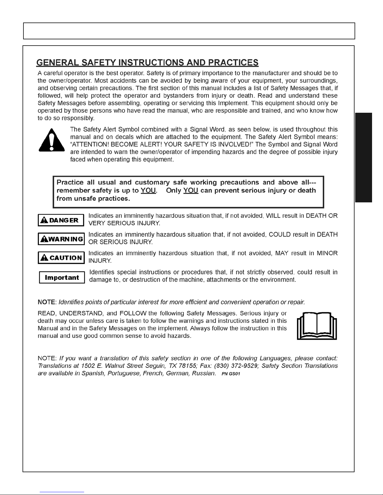
General Safety Instructions and Practices ..........................................................................................................1-1
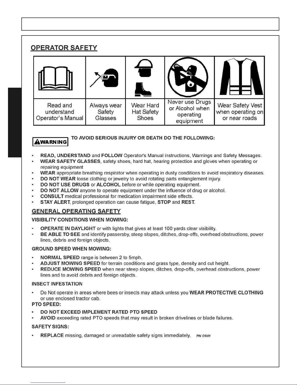
Operator Safety Instructions and Practices.........................................................................................................1-2
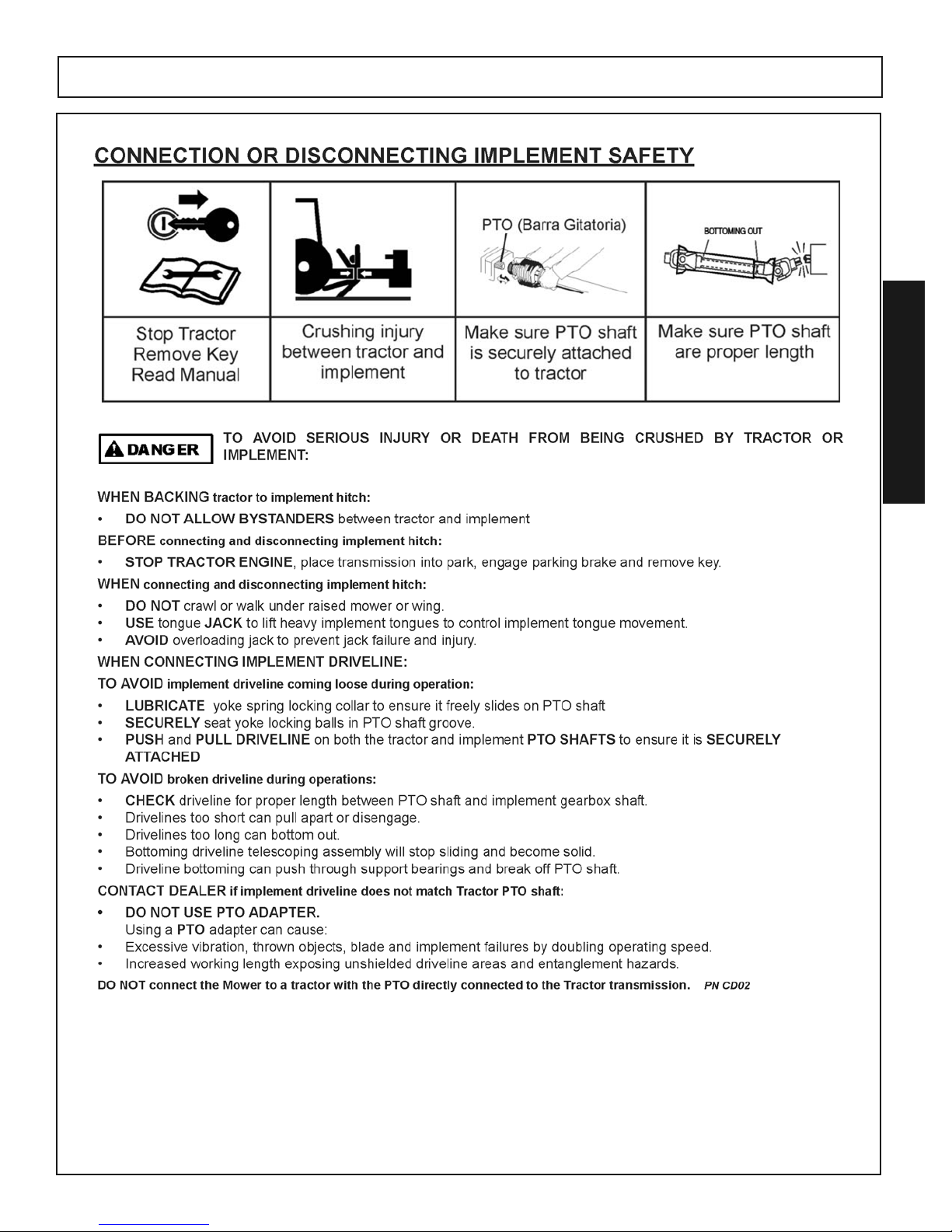
Connecting or Disconnecting Implement Safety Instructions and Practices .......................................................1-3
Crushing Hazards................................................................................................................................................1-4
Thrown Objects Hazards ............................................................................................................................1-5 &1-6
Run Over Hazards...............................................................................................................................................1-7
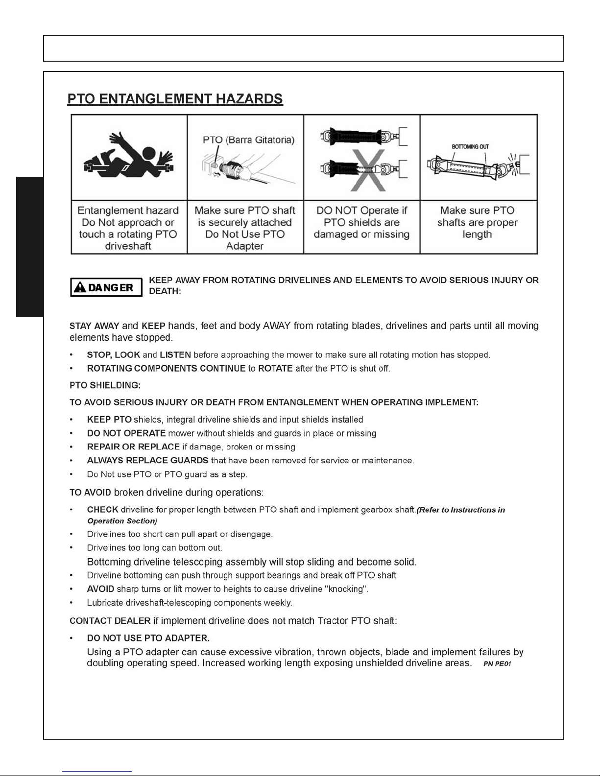
PTO EntanglementHazards.................................................................................................................................1-8
Mower Blade Contact Hazards............................................................................................................................1-9
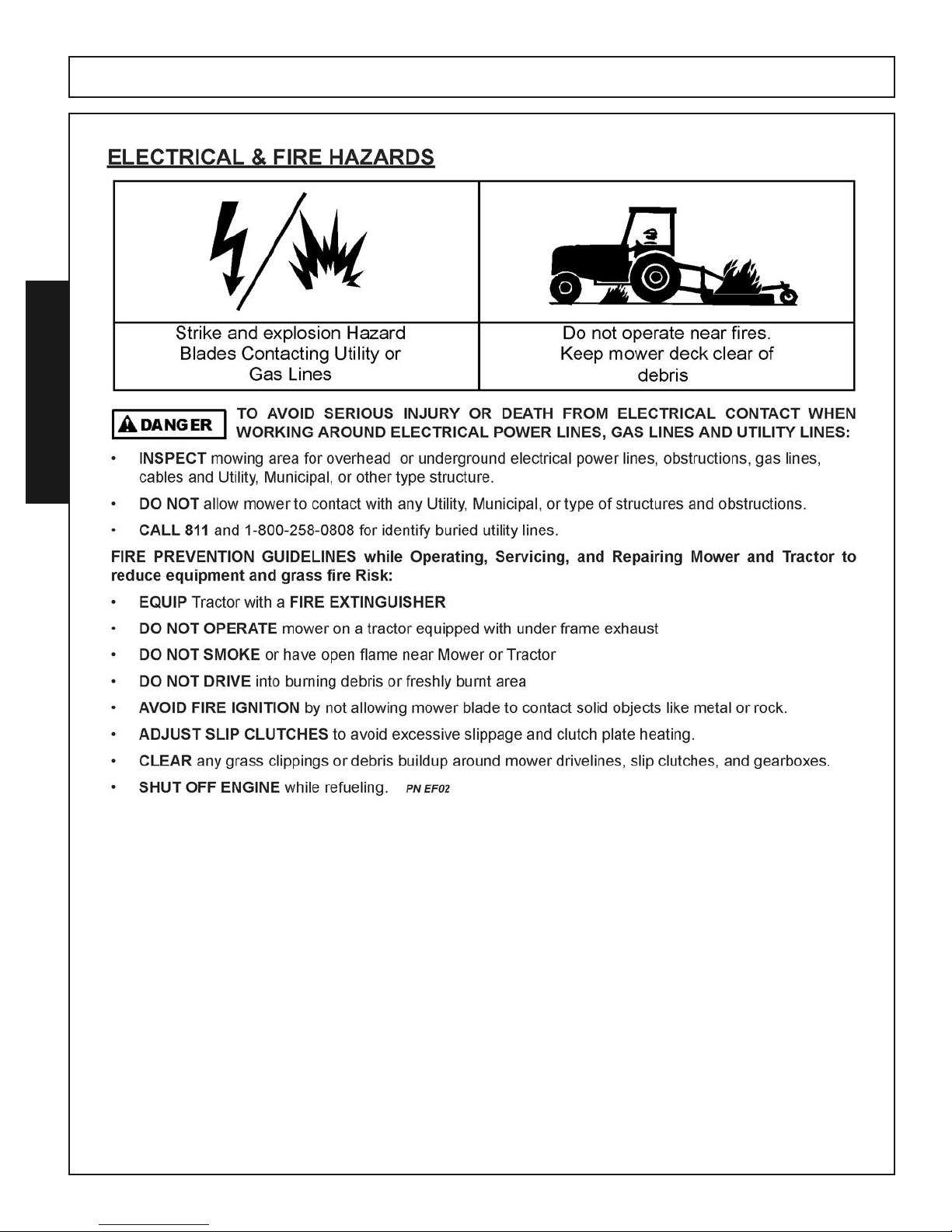
Electrical & Fire Hazards...................................................................................................................................1-10
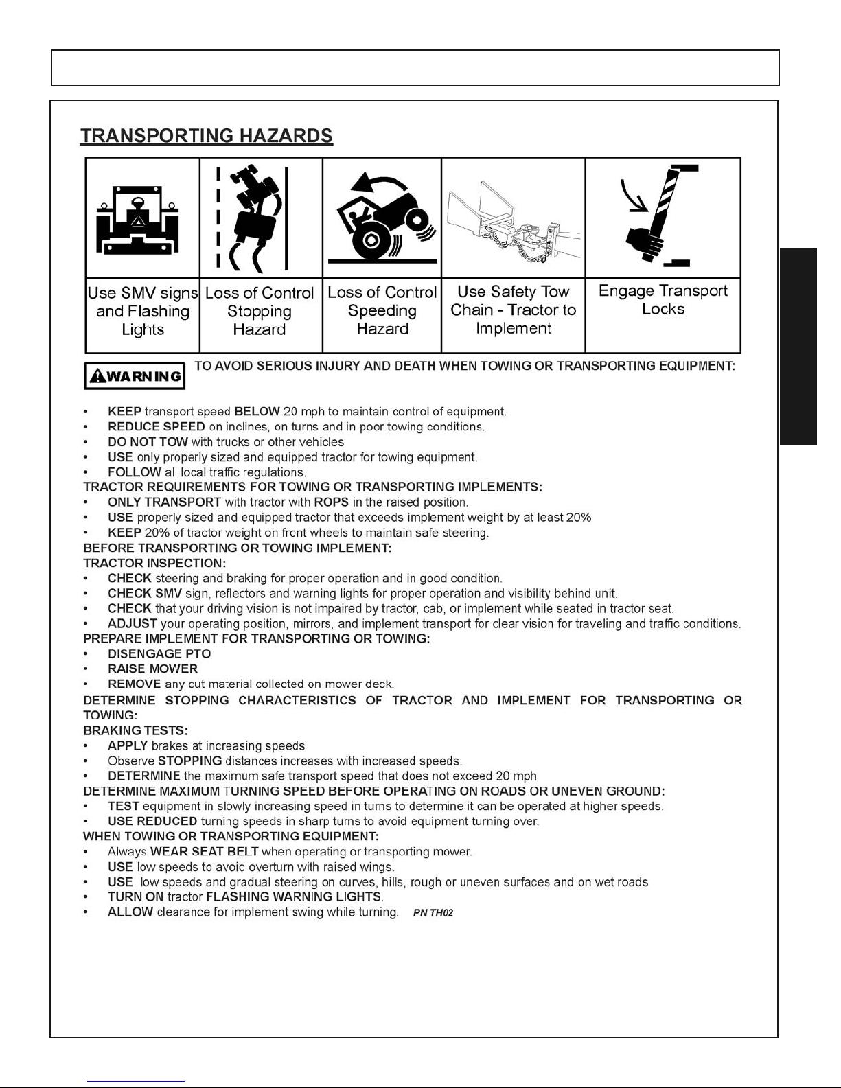
Transporting Hazards ........................................................................................................................................1-11
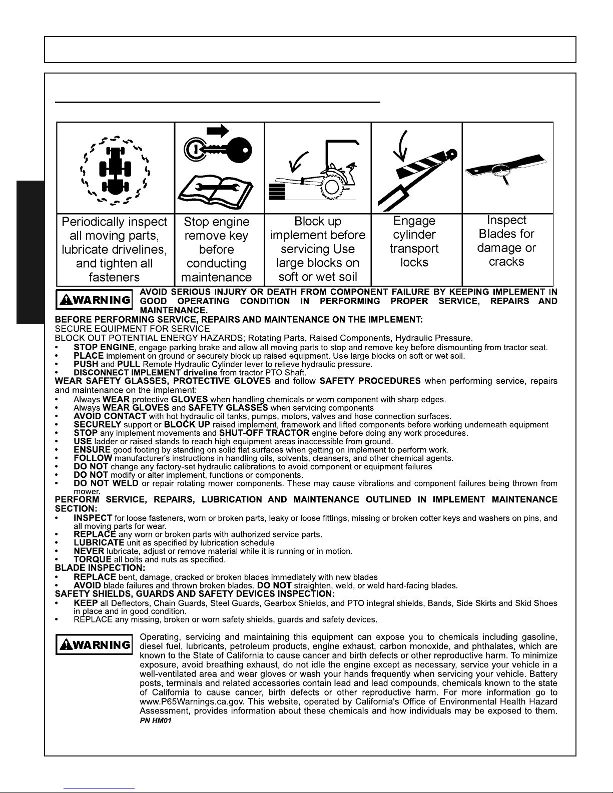
Maintenance Hazards .......................................................................................................................................1-12
Parts Information ...............................................................................................................................................1-13
Decal Location & Description..................................................................................................................1-14 - 1-17
Federal Laws and Regulations..........................................................................................................................1-19
INTRODUCTION SECTION 2
Introduction..........................................................................................................................................................2-1
Description & Equipment Specifications..............................................................................................................2-2
Limited Warranty .................................................................................................................................................2-3
Key Operation Points ..........................................................................................................................................2-4
ASSEMBLY SECTION 3
Dealer Setup Instructions ....................................................................................................................................3-1
Notice (GEARBOX OIL) ......................................................................................................................................3-2
Preparing To Assemble........................................................................................................................................3-3
Assembling the HDTH.........................................................................................................................................3-4
Flex Link Setup (Standard)..................................................................................................................................3-5
Flex Link Setup (Quick Hitch)..............................................................................................................................3-6
Lift Pins................................................................................................................................................................3-7
Caster Wheels.....................................................................................................................................................3-8
Driveline Attachment ...........................................................................................................................................3-9
Front Roller Attachment (OPTIONAL)...............................................................................................................3-10
OPERATION SECTION 4
Operation Instructions .........................................................................................................................................4-1
Operator Requirements.......................................................................................................................................4-2
Tractor Requirements..........................................................................................................................................4-3
Tractor Safety Devices ........................................................................................................................................4-4
Tractor Horsepower.............................................................................................................................................4-4
Tractor 3 Pt. Lift...................................................................................................................................................4-4
Front End Weights...............................................................................................................................................4-4
Power Take Off....................................................................................................................................................4-5
Tire Spacing ........................................................................................................................................................4-5
Getting On and Off The Tractor...........................................................................................................................4-6
Starting the Tractor..............................................................................................................................................4-7
Connecting the Mower to the Tractor .................................................................................................................4-7
Drieline Attachment .............................................................................................................................................4-8
Driveline Length Modification ..............................................................................................................................4-9
Setting the Mower .............................................................................................................................................4-10
Pre-Operation Inspection and Service...............................................................................................................4-11
Mower Pre-Operation Inspection /Service .............................................................................................4-12 & 4-13
Continued On Next Page
5
Page 8

TABLE OF CONTENTS - CONTINUED
OPERATION SECTION 4 (Continued)
Driving the Tractor and Implement..........................................................................................................4-14 - 4-22
Disconnecting the Mower From the Tractor ......................................................................................................4-22
Mower Storage ..................................................................................................................................................4-23
Transporting the Tractor and Implement ...........................................................................................................4-23
Transporting on Public Roadways ..........................................................................................................4-24 - 4-25
Hauling Tractor and Implement .........................................................................................................................4-26
Trouble Shooting.....................................................................................................................................4-27 - 4-28
MAINTENANCE SECTION 5
Lubrication (LUBRICATION POINTS LOCATIONS)............................................................................................5-1
Gearbox Maintenance .........................................................................................................................................5-2
Driveline Maintenance.........................................................................................................................................5-3
Blade Spindle and Belt Tension Idler Arm Lubrication and Maintenance ............................................................5-4
Blade Servicing ...................................................................................................................................................5-5
Blade Sharpening................................................................................................................................................5-5
Blade Removal ....................................................................................................................................................5-6
Blade Installation .................................................................................................................................................5-6
Belt Removal, Belt Replacement.........................................................................................................................5-7
Belt adjustment....................................................................................................................................................5-7
End of Season Storage .......................................................................................................................................5-8
Proper Torque for Fasteners................................................................................................................................5-9
6
Page 9

SAFETY
SECTION
1
Page 10

Page 11
HDTH 7 Finish Mower 10/17
Safety Section 1-1
© 2017 Alamo Group
SAFETY
SAFETY
Page 12
HDTH 7 Finish Mower 10/17
Safety Section 1-2
© 2017 Alamo Group
SAFETY
SAFETY
Page 13
HDTH 7 Finish Mower 10/17
Safety Section 1-3
© 2017 Alamo Group
SAFETY
SAFETY
Page 14
HDTH 7 Finish Mower 10/17
Safety Section 1-4
© 2017 Alamo Group
SAFETY
SAFETY
Page 15
HDTH 7 Finish Mower 10/17
Safety Section 1-5
© 2017 Alamo Group
SAFETY
SAFETY
Page 16
HDTH 7 Finish Mower 10/17
Safety Section 1-6
© 2017 Alamo Group
SAFETY
SAFETY
Page 17
HDTH 7 Finish Mower 10/17
Safety Section 1-7
© 2017 Alamo Group
SAFETY
SAFETY
Page 18
HDTH 7 Finish Mower 10/17
Safety Section 1-8
© 2017 Alamo Group
SAFETY
SAFETY
Page 19

HDTH 7 Finish Mower 10/17
Safety Section 1-9
© 2017 Alamo Group
SAFETY
SAFETY
Page 20
HDTH 7 Finish Mower 10/17
Safety Section 1-10
© 2017 Alamo Group
SAFETY
SAFETY
Page 21
HDTH 7 Finish Mower 10/17
Safety Section 1-11
© 2017 Alamo Group
SAFETY
SAFETY
Page 22
HDTH 7 Finish Mower 10/17
Safety Section 1-12
© 2017 Alamo Group
SAFETY
SAFETY
HAZARDS WITH MAINTENANCE OF IMPLEMENT
Page 23

HDTH 7 Finish Mower 10/17
Safety Section 1-13
© 2017 Alamo Group
SAFETY
SAFETY
Page 24
HDTH 7 Finish Mower 10/17
Safety Section 1-14
© 2017 Alamo Group
SAFETY
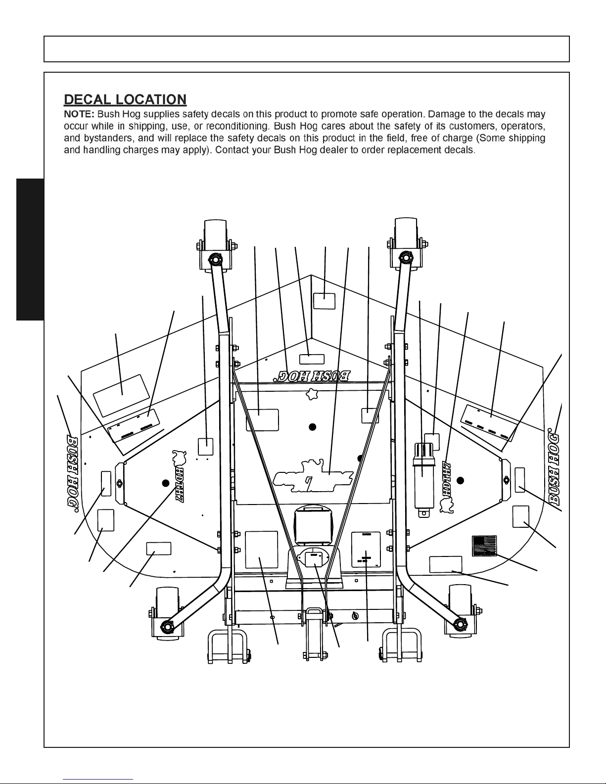
SAFETY
q
w
e
r
t
t
t
y
y
y
u
i
o
1)
1!
1@
1#
1^
1
o
1&
1
1*
1$
1$
1%
Page 25

HDTH 7 Finish Mower 10/17
Safety Section 1-15
© 2017 Alamo Group
SAFETY
SAFETY
ITEM PART QUANITY DESCRIPTION
NO. NO.
1 D855 1 Danger Decal, Multilingual
2 D546 1 Danger Decal, Guard Missing
3 D559 1 Genuine Parts Decal
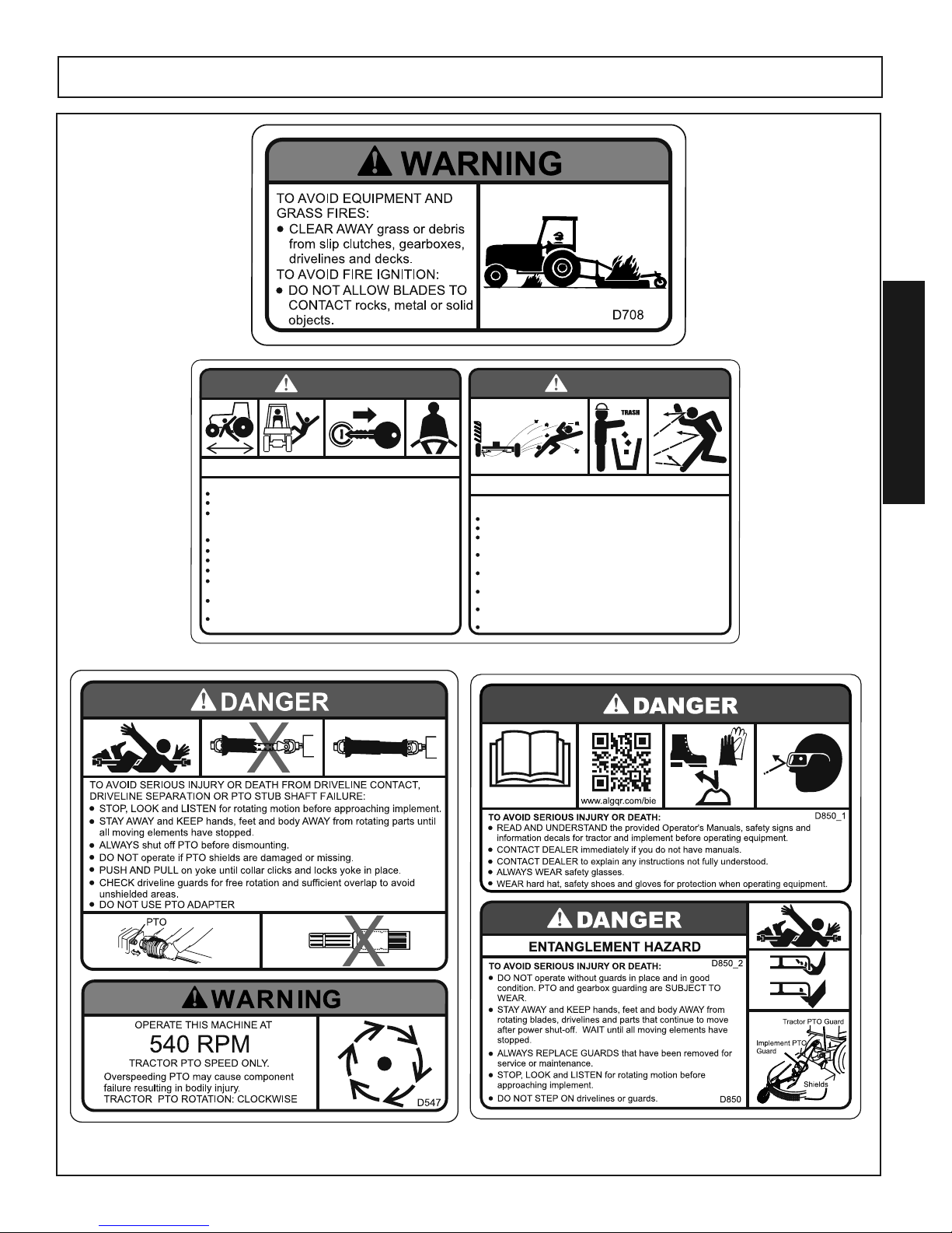
4 D547 1 Danger / Warning Decal, Driveshaft / PTO
5 D646 3 Danger, Guard Missing
6 D418 3 Danger Decal, Blade Contact
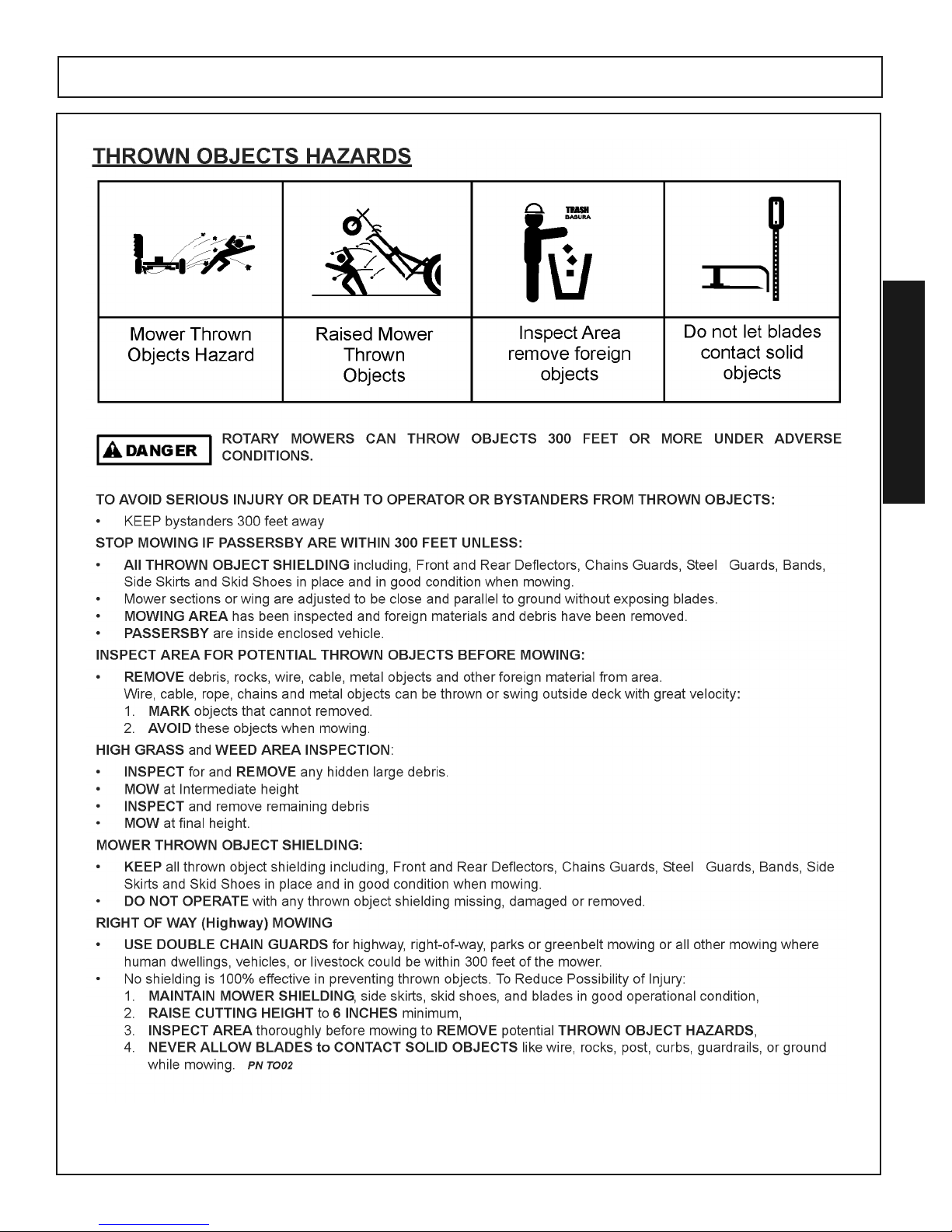
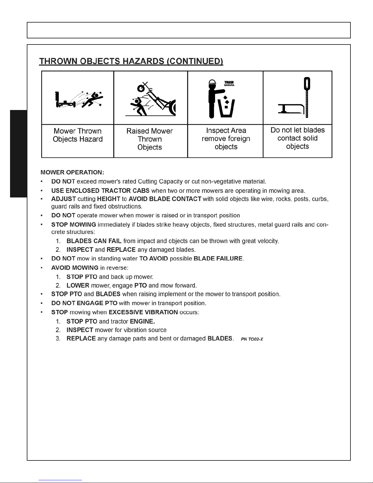
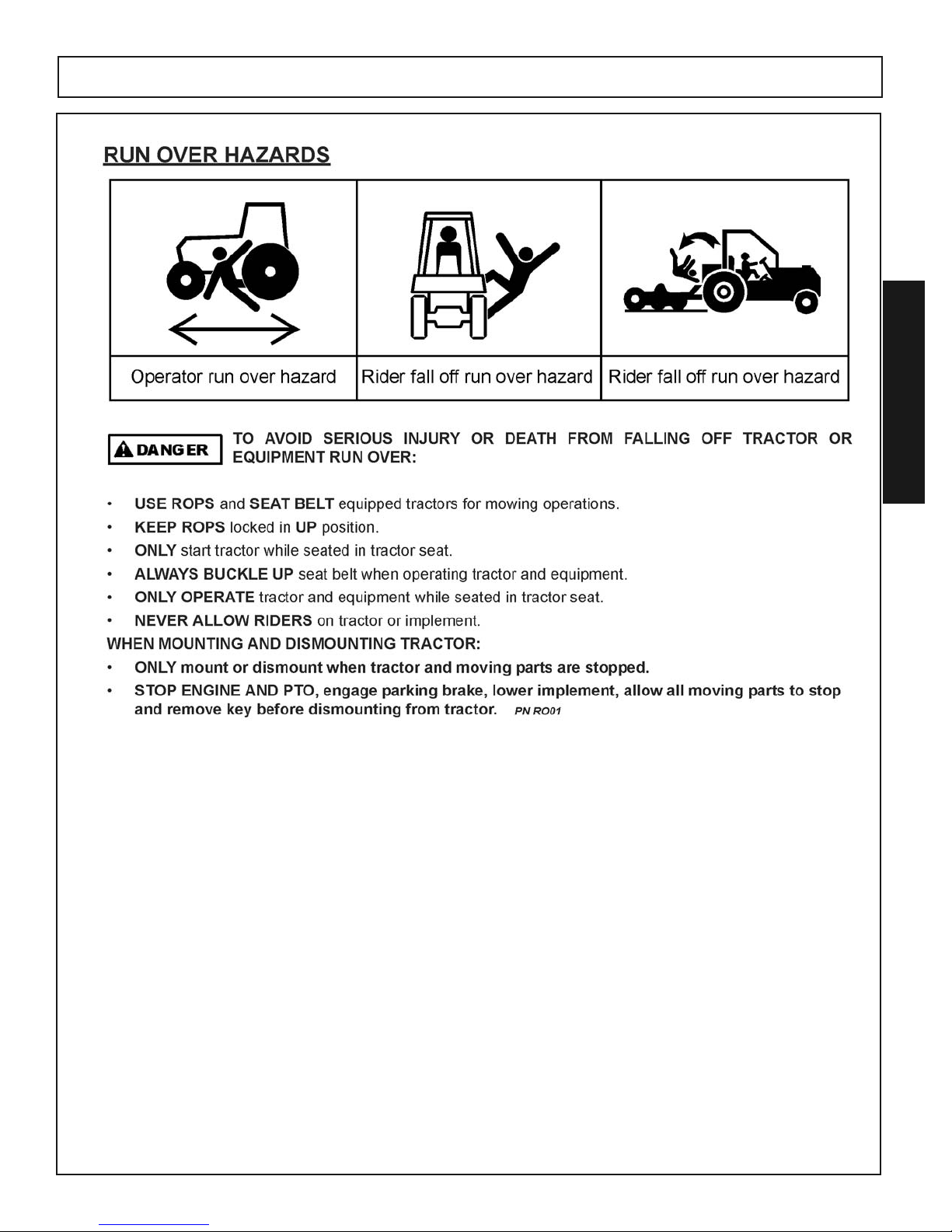
7 D851 1 Danger Decal, Run Over and Thrown Object Hazard
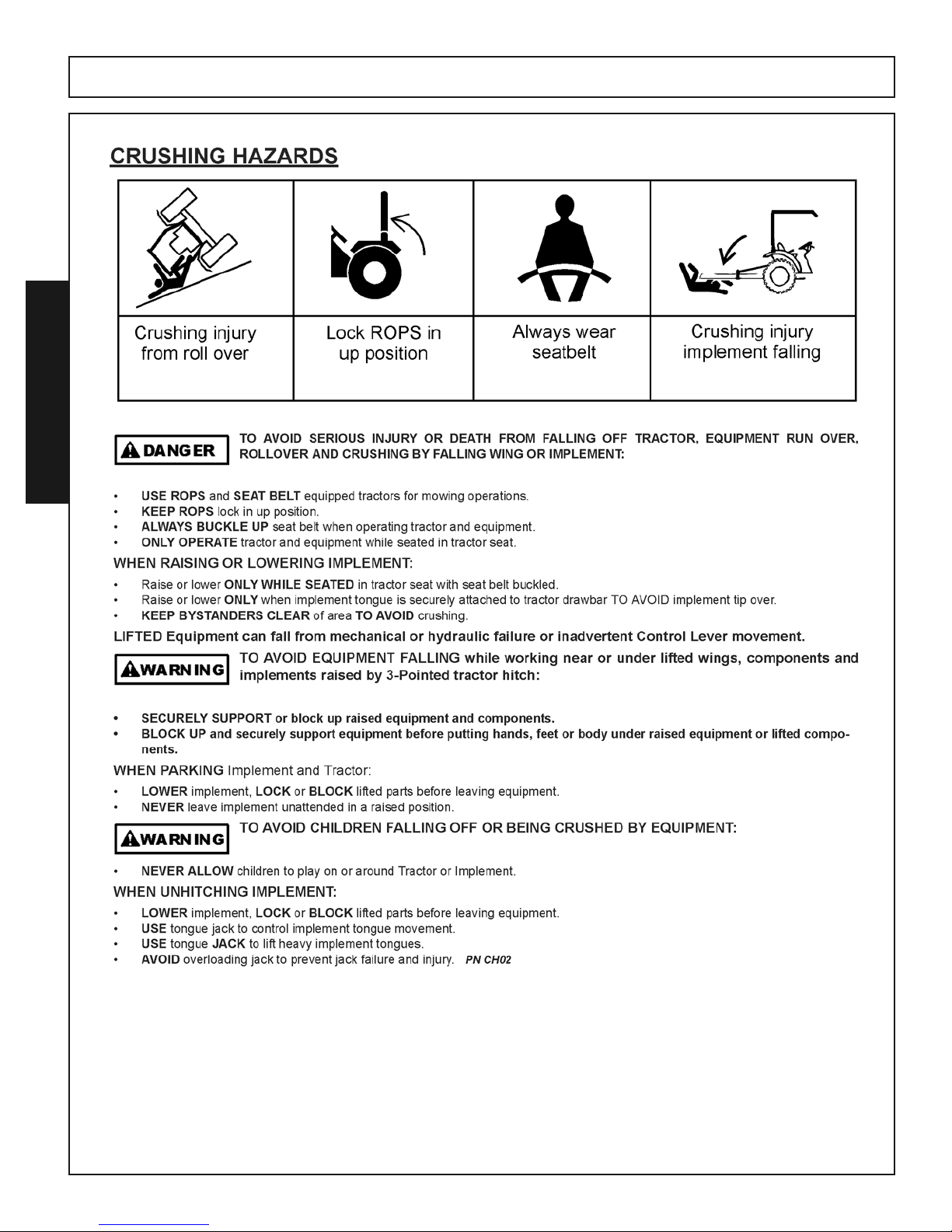
8 D852 1 Danger Decal, Crushing Hazard
9 D641 3 Warning Decal, Pinch Point Hazard
10 D850 1 Danger Decal, Entanglement Hazard
11 50038320 1 Belt Installation Decal
12 50074259 1 Made in America Decal
13 50078567 3 Bush Hog Logo Decal
14 50078485 2 Model Decal HDTH7
15 50078568 2 Bush Hog Logo Turf Decal
16 50035829 1 Owners Manual Tube
* 50078297 1 Owners Manual
17 D708 1 Warning Decal, Avoid Equipment and Grass Fires
18 50031214 2 Red Reflector
*Not Shown
Page 26

HDTH 7 Finish Mower 10/17
Safety Section 1-16
© 2017 Alamo Group
SAFETY
SAFETY
D646
D559
D418
D546
D641
Page 27
HDTH 7 Finish Mower 10/17
Safety Section 1-17
© 2017 Alamo Group
SAFETY
SAFETY
D850
D547
D851
D708
DANGER
Run Over Hazard - Injury or Death
TO AVOID SERIOUS INJURY OR DEAT H:
ALWAYS BUCKLE UP seat belt.
ONLY START Tractor while seated in the operator's seat.
STOP ENGINE and PTO, engage parking brake, lower implement,
allow all moving parts to stop and remove key before dismounting
from tractor.
KNOW HOW to stop tractor and equipment quickly for an emergency.
DO NOT MOUNT or DISMOUNT Tractor in motion.
NEVER ALLOW riders on tractor or implement.
NEVER ALLOW children to operate or ride on tractor or implement.
KEEP BYSTANDERS CLEAR of area before moving tractor or
implement.
KEEP ALERT and AVOID hitting stumps, holes, ruts, and
uneven terrain.
AVOID tree limbs, brush and other overhanging objects that can
strike and throw the operator from seat.
D851_1
DANGER
D851_2
THROWN OBJECTS HAZARD
Mower can throw objects up to 300 feet. TO AVOID SERIOUS
INJURY OR DEATH to operator or bystanders:
STOP mowing if bystanders or traffic come within 300 feet.
DO NOT OPERATE with thrown object shielding removed.
KEEP thrown object shielding in place and in good condition during
operation. Thrown Objects shielding is subject to wear.
REPAIR OR REPLACE shielding if damaged, broken or missing. See
Operator’s Manual for all Shields and Guards.
INSPECT area for potential mower thrown object hazards before
mowing.
Remove and AVOID objects such as wire, cable, metal objects and
all other foreign material.
DO NOT ALLOW blades to contact solid objects like wire, rocks,
posts, curbs or guard rails.
DO NOT OPERATE in transport position or with wings off ground.
D851
Page 28
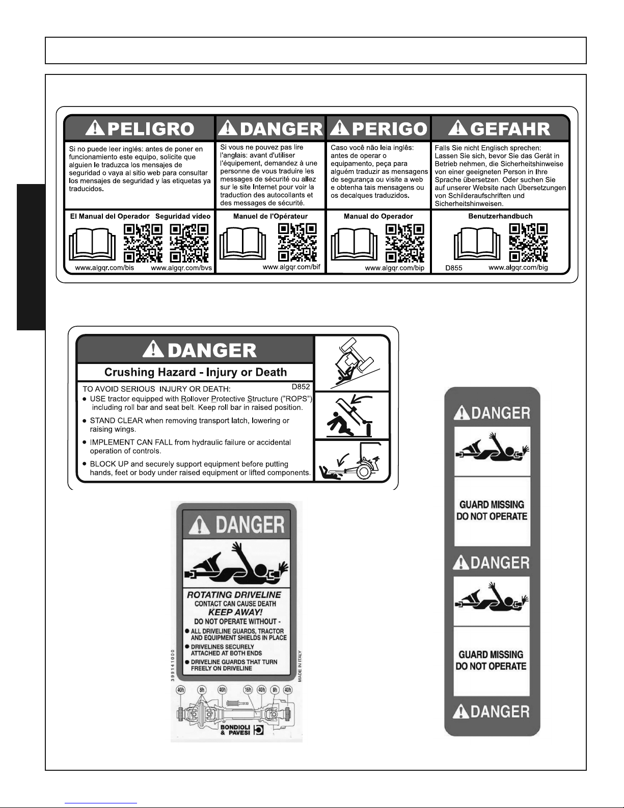
D855
HDTH 7 Finish Mower 10/17
Safety Section 1-18
© 2017 Alamo Group
SAFETY
SAFETY
D852
Page 29

HDTH 7 Finish Mower 10/17
Safety Section 1-19
© 2017 Alamo Group
SAFETY
SAFETY
Federal Laws and Regulations
This section is intended to explain in broad terms the concept and effect of federal laws and regulations concerning
employer and employee equipment operators. This section is not intended as a legal interpretation of the law and
should not be considered as such.
Employer-Employee Operator Regulations
U.S. Public Law 91-596 (The Williams-Steiger Occupational and Health Act of 1970) OSHA
This Act Seeks:
“...to assure so far as possible every working man and woman in the nation safe and healthful working
conditions and to preserve our human resources...”
DUTIES
Sec. 5 (a) Each employer(1) shall furnish to each of his employees employment and a place of employment which are free from
recognized hazards that are causing or are likely to cause death or serious physical harm to his employees;
(2) shall comply with occupational safety and health standards promulgated under this Act.
(b)
Each employee shall comply with occupational safety and health standards and all rules, regulations
and
orders issued pursuant to this Act which are applicable to his own actions and conduct.
OSHA Training Requirements
Title 29, Code of Federal Regulations Part 1928.57(a)(6). www.osha.gov
Operator instructions. At the time of initial assignment and at least annually thereafter, the employer shall
instruct every employee who operates an agricultural tractor and implements in the safe operating practices
and servicing of equipment with which they are or will be involved, and of any other practices dictated by the
work environment.
Keep all guards in place when the machine is in operation;
Permit no riders on equipment
Stop engine, disconnect the power source, and wait for all machine movement to stop before servicing,
adjusting, cleaning or unclogging the equipment, except where the machine must be running to be properly
serviced or maintained, in which case the employer shall instruct employees as to all steps
and procedures
which are necessary to safely service or maintain the equipment.
Make sure everyone is clear of machinery before starting the engine, engaging power, or operating the
machine.
Employer Responsibilities:
To ensure employee safety during Tractor and Implement operation, it is the employer’s responsibility to:
1. Train the employee in the proper and safe operation of the Tractor and Implement.
2. Require that the employee read and fully understand the Tractor and Implement Operator’s manual.
3. Permit only qualified and properly trained employees to operate the Tractor and Implement.
4. Maintain the Tractor and Implement in a safe operational condition and maintain all shields and guards on the
equipment.
5. Ensure the Tractor is equipped with a functional ROPS and seat belt and require that the employee operator
securely fasten the safety belt and operate with the ROPS in the raised position at all times.
6. Forbid the employee operator to carry additional riders on the Tractor or Implement.
7. Provide the required tools to maintain the Tractor and Implement in a good safe working condition and provide
the necessary support devices to secure the equipment safely while performing repairs and service.
8. Require that the employee operator stop operation if bystanders or passersby come within 300 feet.
Child Labor Under 16 Years of Age
Some regulations specify that no one under the age of 16 may operate power machinery. It is your responsibility
to know what these regulations are in your own area or situation. (Refer to U.S. Dept. of Labor, Employment Standard
Administration, Wage & Home Division, Child Labor Bulletin #102.)
Page 30

Page 31

INTRODUCTION
SECTION
2
Page 32

Page 33

HDTH 7 Finish Mower 10/17
Introduction Section 2-1
© 2017 Alamo Group
INTRODUCTION
INTRODUCTION
We are pleased to have you as a Bush Hog customer. Your HDTH Series Rotary Cutter has
been carefully designed to give maximum service with minimum down time.This manual is provided to give you the necessary operating and maintenance instructions for keeping your rotary
cutter in top operating condition. Please read this manual thoroughly. Understand what each
control is for and how to use it. Observe all safety precautions decaled on the machine and
noted throughout the manual for safe operation of implement. If any assistance or additional information is needed, contact your authorized Bush Hog dealer.
Bush Hog provides shielding on all mower products manufactured by Bush Hog to protect the
operator, passersby, livestock and property from thrown objects. NO shielding is 100% effective
in preventing thrown objects. This possibility can be substantially reduced by maintaining the
mower and shielding in good operational condition, inspecting the area for foreign debris before
mowing, keeping persons a minimum distance of 300 feet from the mower at all times of operation.
Safety is of primary importance to the owner/operator and the manufacturer. Observe all Safety
Precautions decaled on the machin and noted throughout this manual for safe operation of this
implement. For additional assistance or information contact your authorized Bush Hog dealer.
The owner/ operator should know and understand the Safety Messages before assembly and
be aware of the hazards of operating this cutter during assembl, use and maintenance.
The Safety Alert Symbols along with a Signal Word, as seen below, is intended to Warn the
owner/operator of impending hazards and the degree of possible injury faced when operating
this machine.
Page 34

HDTH 7 Finish Mower 10/17
Introduction Section 2-2
© 2017 Alamo Group
INTRODUCTION
INTRODUCTION
2-1 DESCRIPTION
The HDTH cutters (Figure 2-1) are grooming mowers intended for cutting lawns, golf courses, athletic fields, or any
maintained area where a clean, uniform finish is desired. Uplift blades form a suction during operation to lift the grass
before cutting it. The caster wheel arrangement along with the floating lift linkage and optional front roller, all work
together to give an even cut and minimize scalping.
Power from the tractor is transmitted through a telescoping driveline to the gearbox. It is then passed to the spindle
housings by a single, B-section, Aramid Cord reinforced belt. Drivetrain protection is provided by belt slippage.
Fig. 2-1
Description Model HDTH7
Cutting Width..................................................60”
Cutting Height (1/2" incr.) ...............................1 1/2" - 6 1/2"
Tractor HP Range .........................................30-55 PTO
Hitch Type ......................................................Cat I & II Std. & QH
Blade Size ......................................................5/16" x 2 1/2 x 29"
Number of Blades ..........................................3
Blade Tip Speed.............................................18,266 FPM
Blade Overlap ................................................1 1/2"
Blade Uplift.....................................................Parallel
Driveline Size .................................................ASAE Cat 3
Front Roller (optional) ....................................3" x 13"
Discharge .......................................................Rear
Deck Thickness..............................................7ga
Tires ...............................................................4 X 10 Solid
Belts ...............................................................(1) "B" Aramid Cord
Belt Adjustment ..............................................Spring-Loaded Idler
EQUIPMENT SPECIFICATIONS
HDTH7
Page 35

HDTH 7 Finish Mower 10/17
Introduction Section 2-3
© 2017 Alamo Group
INTRODUCTION
INTRODUCTION
Page 36

HDTH 7 Finish Mower 10/17
Introduction Section 2-4
© 2017 Alamo Group
INTRODUCTION
INTRODUCTION
Page 37

ASSEMBLY
SECTION
3
Page 38

Page 39

HDTH 7 Finish Mower 10/17
Assembly Section 3-1
© 2017 Alamo Group
ASSEMBLY
ASSEMBLY
DEALER SETUP INSTRUCTIONS
The mower as received from the factory is partially assembled and requires minimum time to complete assembly
and is ready for sale.
This mower is shipped vertically with shipping brackets. These shipping brackets are intended for use in transporting the mower from the factory to dealer.
DO NOT use these brackets to store the unit. DO NOT store mower vertically, the mower
can fall over resulting in serious injury or death. To avoid injury always store mower lying
down on flat ground.
Assembly will be easier if components are aligned and loosely assembled before tightening hardware. Refer to
bolt torque chart in Maintenance Section. All bolts are grade 5 unless otherwise specified.
DO NOT attempt any assembly while the machine is still attached to theshipping brackets and standing in the vertical position.
Serious injury or death could occur fromthe machinefalling over.
Assembly must be performed with the machine placed on a hard levelsurface
with the shipping brackets revoved.
Page 40

HDTH 7 Finish Mower 10/17
Assembly Section 3-2
© 2017 Alamo Group
ASSEMBLY
ASSEMBLY
NOTICE!
The HDTH7 Gearboxes are shipped
WITHOUT OIL in the Gearboxes and must
be filled before connecting to the tractor
and placing in operation!
USE 85W / 90 GEAR OIL
OIL FILL PROCEDURE
DO NOT OVER FILL GEARBOXES.
1. Remove the Oil Filler/Vent Plug on top the Gearbox.
2. Remove Fill Check Plug on the side of the Gearbox.
3. Add 85W/90 Gear Oil until it starts to run out of the Check Plug hole.
4. Allow enough time for the oil to seep into the lower housing and add additional oil if necessary.
5. Reinstall the vent plug and the check plug.
Oil Filler/Vent Plug
Fill Check Plug
Page 41

The HDTH models are shipped from the factory partially assembled on shipping stands allowing
the machine to be shipped in a vertical position. The shipping stands attached to the front of
the machines must be removed prior to the assembly process.
Do not attempt to remove the shipping stands with the machine in the vertical
position.
PREPARING TO ASSEMBLE
1. With the aid of a overhead winch or a fork lift, lower the cutter to the ground so that it is resting securely on a firm flat surface
2. Remove Shipping Stands
3. Remove the Driveshaft, Mast Halves and Mast Supports from the machine.
4. Remove the Bag of Parts from under the shielding.
5. Leave the Caster Wheels in the shipping position at this time.
HDTH 7 Finish Mower 10/17
Assembly Section 3-3
© 2017 Alamo Group
ASSEMBLY
ASSEMBLY
Figure 3-1
HDTH
as shipped in
vertical position.
Mast Supports
Driveshaft Assembly
Mast Halves
Shipping Stand
Bag of parts Located
under shield
Caster Wheels
Page 42

HDTH 7 Finish Mower 10/17
Assembly Section 3-4
© 2017 Alamo Group
ASSEMBLY
ASSEMBLY
q
q
o
i
i
1!
1!
1)
1)
1@
1#
1^
1^
1&1*1(
1%
1%
1$
1$
w
w
e
e
u
y
t
t
r
r
Figure 3-2
HDTH
Assembly
Diagram
ASSEMBLING THE HDTH (Figure 3-2)
1. Install the Lift Arms q into the pockets at the front of the machine. Install the category I/II lift pin w in the front
hole in the lift arms and secure with the Lynch Pin.
2. Insert a 1 ” x 2-3/4” Clevis Pin
e into the front hole of the pocket and the middle hole of the Lift Arm q. Fasten
with the Presto Pins
r from the Bag of Parts.
3. Install the Mast Halves
t with the slot at the bottom and over the Clevis Pin e. Align the hole above the slot
with the hole in the mount and install a 5/8” x 1-3/4” bolt y through each and fasten with the 5/8” Flanged Locknuts
u from the Bag of Parts.
4. Attach the Mast Supports
i to the outside of the top holes in the Mast Halves t. Place a 1” Slot Bushing 1) to
each of the slots in the Mast Supports
i. Place a 5/8” Flatwasher 1! on the 5/8” x 6” bolt o and install through
the Slot Bushing 1) and Mast Support
i Mast t. Place the 1-1/8” x 3-3/16” Spacer 1@ between the Mast Up-
rights and slide the 6” bolt through the Mast, Mast Support, Slot Bushing and 5/8” Flatwasher. Install a 5/8”
Locknut
1# to the bolt and tighten.
5. Attach the Mast Supports
i to the rear of the machine by removing the 5/8” lock nuts 1$ and 5/8” flatwashers
1%. Leave the 1” Bushing 1^ on the bolt shank and place the hole in the Mast Supports i over the Bushings
1^. Re-install the 5/8” flatwasher 1% and 5/8” lock nut 1$ and tighten.
6. Install the Driveline Holder
1& in the hole of the Mast Half from the under side. With the Mounting Rod of the
Driveline Holder through the hole in the Mast Half, place a 1/2” Flatwasher
1* over the Mounting Rod and install
the 5/32”” x 1” Cotter Pin
1( through the hole in the rod. (See Detail “A”)
Detail “A”
Cotter Pin
5
⁄32 ” x 1”
1(
Flatwasher
5
⁄8
” 1*
Mast t
Driveline Holder 1&
See Detail “A”
See CASTER WHEELS
Figure 3-6
See LIFT PINS
Figure 3-5
See FLEX LINK
Setup Instructions.
Figure 3-3 or Figure 3-4
Page 43

HDTH 7 Finish Mower 10/17
Assembly Section 3-5
© 2017 Alamo Group
ASSEMBLY
ASSEMBLY
FLEX LINK SETUP
Standard 3 Pt Lift (Figure 3-3)
For standard 3 pt. lift attachment to tractor the Flex Link is attached to the mast in the upper holes just under the
Mast Struts. Refer to Figure 3-3.
1. Place a Pivot Bushing through the rear holes of the Flex Link and install between the Mast uprights aligning
the Bushing in the Flex Link with the holes in the Mast.
2. Insert a 5/8” x 5-1/2” bolt through the assembly and fasten with 5/8” lockwasher and 5/8” hex nut from bag of
parts.
3. Place a Pivot Bushing between the Mast uprights in the lower holes aligning the Bushing with the holes in the
Mast and fasten with a 5/8” x 5-1/2” bolt, 5/8” lockwasher and 5/8” hex nut from bag of parts.
Alternate 3 Pt Lift (Figure 3-3A) - Provides Additional Transport Height
For Alternate 3 pt. lift attachment to tractor the Flex Link is attached to the mast in the upper holes above the Mast
Struts. Refer to Figure 3-3A.
1. Place a Pivot Bushing through the rear holes of the Flex Link and install between the Mast uprights aligning
the Bushing in the Flex Link with the holes in the Mast.
2. Insert a 5/8” x 5-1/2” bolt through the assembly and fasten with 5/8” lockwasher and 5/8” hex nut from bag of
parts.
3. Place a Pivot Bushing between the Mast uprights in the lower holes aligning the Bushing with the holes in the
Mast and fasten with a 5/8” x 5-1/2” bolt, 5/8” lockwasher and 5/8” hex nut from bag of parts.
Pivot Bushing
3-3/16” x 1-1/8”
Pivot Bushing
3-3/16” x 1-1/8”
5/8” x 5-1/2” Bolt
5/8” Lockwasher
5/8” Hex Nut
5/8” x 5-1/2” Bolt
5/8” Lockwasher
5/8” Hex Nut
5/8” x 5-1/2” Bolt
5/8” Lockwasher
5/8” Hex Nut
5/8” x 5-1/2” Bolt
5/8” Lockwasher
5/8” Hex Nut
Figure 3-3
Flex Link
Flex Link
Pivot Bushing
3-3/16” x 1-1/8”
Pivot Bushing
3-3/16” x 1-1/8”
Figure 3-3A
Page 44

FLEX LINK SETUP (continued)
Quick Hitch 3 Pt Lift (Figure 3-4)
For Quick Hitch pt. lift attachment to tractor the Flex Link is attached to the Mast in the lower
holes of the Mast Struts. Refer to Figure 3-4.
1. Before assembling the Flex Link to the Mast the Extension Spring should be installed to the
Pivot Bushing. It will be necessary to slightly pry the Spring open to allow the bushing to be
inserted into the loop. Move the spring so that it centered on the Pivot Bushing.
2. Place the Pivot Bushing between the Mast uprights and align Pivot Bushing with upper hole.
Install a 5/8” x 5-1/2” bolt through the Mast and Bushing and fasten using a 5/8” lockwasher
and 5/8” hex nut.
3. Place a Pivot Bushing through the rear holes of the Flex Link and install between the Mast
uprights. Tilt the Flex Link to allow the loop of the Spring to be inserted through the hole located on the rear of the Flex Link. align the Bushing in the Flex Link with the holes in the
Mast and fasten using a 5/8” x 5-1/2” bolt , 5/8” lockwasher and 5/8” hex nut.
4. In the front hole in the Flex Link install a 3/4” x 4” bolt with the Top Link Bushing between the
Flex Link ears and fasten with a 3/4” lock nut.
HDTH 7 Finish Mower 10/17
Assembly Section 3-6
© 2017 Alamo Group
ASSEMBLY
ASSEMBLY
Pivot Bushing
3-3/16” x 1-1/8”
Pivot Bushing
3-3/16” x 1-1/8”
Top Link Bushing
1-1/4” x 2”
5/8” x 5-1/2” Bolt
5/8” Lockwasher
5/8” Hex Nut
5/8” x 5-1/2” Bolt
5/8” Lockwasher
5/8” Hex Nut
3/4” x 4” Bolt
3/4” Lock Nut
Flex Link
Figure 3-4
Spring
Page 45

HDTH 7 Finish Mower 10/17
Assembly Section 3-7
© 2017 Alamo Group
ASSEMBLY
ASSEMBLY
LIFT PINS
Lift Pins 3 Pt Lift (Figure 3-5)
1. Install the Lift Arms into the pockets at the front of the machine. Install the category I & II lift pin in the front hole
in the lift arms and secure with the Lynch Pin.
2. Insert a 1” x 2-3/4” Clevis Pin into the front hole of the pocket and the middle hole of the Lift Arm. Fasten with
the Presto Pins from the Bag of Parts
Lynch Pin
Category I & II
Lift Pin
Category I & II
Lift Arm
Figure 3-5
1” x 2-3/4”
Clevis Pin
Presto Pin
Page 46

CASTER WHEELS (Figure 3-6)
The Caster Wheels are shipped in the inverted position from the factory and must be placed in the correct operating
position for final assembly.
1. Raise and support the front of the mower enough so the Casters may be placed through the pivot tubes on the
wheel mounts from the underside.
2. Remove the retaining pin and slide the height adjusting spacers off the Caster and remove the Caster Assembly
from Pivot Tube.
3. Determine the cutting height desired and place the required spacers on the Caster pivot Shaft and slide the
caster pivot shaft back through the Pivot Tube. Install the unused spacers on the Pivot Shaft and install the re-
taining pin.
NOTE: There are (4) 1” and (1) 1/2” Height Adjusting Spacers per Caster Wheel Assembly.
Cutting Height can be achieved by placing a combination of Spacers either above or beneath the Pivot Tube.
4. Repeat the process on all the Caster Wheel assemblies. Be sure the Spacers are set up the same on all four
Casters.
5. Lower mower to ground, resting on the Caster Wheels.
HDTH 7 Finish Mower 10/17
Assembly Section 3-8
© 2017 Alamo Group
ASSEMBLY
ASSEMBLY
Retaining
Pin
1/2” Spacer
Pivot
Tube
Figure 3-6
1” Spacers
1” Spacers
Page 47

HDTH 7 Finish Mower 10/17
Assembly Section 3-9
© 2017 Alamo Group
ASSEMBLY
ASSEMBLY
DRIVELINE ATTACHMENT (Figure 3-7)
The Driveline Supplied with the HDTH Series Finish Mowers are ASAE size 3 with 1-3/8”- 6 spline yokes.The implement yoke may have a locking push pin or a locking collar for the driveline to lock to the implement gearbox
shaft. The tactor yoke of the driveline is a locking collar style
.
Place the yoke with the locking push pin or locking collar locking ring on the implement gearbox shaft depress the
locking pin or slide the collar back and slide the yoke on the gearbox shaft until the locking pin or locking balls engage the locking groove of the gearbox shaft. Release pin or collar and give a firm tug on the driveline to be sure
the driveline is locked in the groove.
Figure 3-7
Lock Collar
Locking Ring
Locking Push Pin
or
Lock Collar Locking
Ring
IMPORTANT: Scan this QR Code with your smart phone to link to the ADMA
Driveline Safety Manual for more information on the safe use of a driveline during
normal operation and maintenance. Or type in your internet browser the following
web address: www.algqr.com/dme
Ops-0009-MISC
Page 48

HDTH 7 Finish Mower 10/17
Assembly Section 3-10
© 2017 Alamo Group
ASSEMBLY
ASSEMBLY
FRONT ROLLER KIT ASSEMBLY (OPTIONAL) (Figure 3-8)
1. Attach the Roller Mounting Brackets to the front of the deck using two 3/8” x 1” carriage bolts, , 3/8” lockwashers
and 3/8” hex nuts in the front mounting holes and two 3/8” x 1-1/4” carriage bolts, 3/8” lockwashers and 3/8”
hex nuts in the rear mounting holes as shown in figure (Figure 3-8) below.
2. Place the sleeve in the roller and a 3/4” flatwasher on each end.
3, Place the roller and sleeve assembly between the mounting brackets. Align the holes and insert the stud
through the mounting brackets and the roller assembly.
4. Attach a 1/2” locknut to each end of the stud and tighten.
3/4” Flatwasher
3/4” Flatwasher
Sleeve
Roller
R.H. Roller
Bracket
L.H. Roller
Bracket
Rear Holes
3/8” x 1-1/4” Bolts
3/8” Lockwashers
3/8” Hex Nuts
Front Holes
3/8” x 1” Bolts
3/8” Lockwashers
3/8” Hex Nuts
Figure 3-8
1/2” Locknut
each end
Stud
Page 49

OPERATION
SECTION
4
Page 50

Page 51

HDTH 7 Finish Mower 10/17
Operation Section 4-1
© 2017 Alamo Group
OPERATION
OPERATION
BUSH HOG HDTH SERIES FINISH MOWER
OPERATION INSTRUCTIONS
Bush Hog HDTH Finish Mowers are manufactured with quality materials by skilled workers. These mowers are
grooming mowers intended for cutting lawns, golf courses, athletic fields or any other maintained areas where a
clean, uniform finish is desired. The mower is equipped with protective deflectors to prevent objects from being
thrown from the mower by the blades. All deflectors and shielding equipped on this unit must be maintained in
good working operational condition.
It is the operator’s responsibility to be knowledgeable of all potential operating hazards and to take every reasonable precaution to ensure oneself, others, animals and property are not injured or damaged by the mower, tractor
or a thrown object. Do not operate the mower if passersby, pets, livestock or property are within 300 feet of the
unit unless:
• ALL THROWN OBJECT SHIELDING, Including deflectors, Chain Guards (If equipped), Steel Guards and
Side Skirts are in place and in good condition while mowing.
• Mower is adjusted to be parallel to ground without exposing blades.
• MOWING AREA has been inspected and foreign materials and debris have been removed.
• PASSERSBY are inside an enclosed vehicle.
This section of this manual is designed to familiarize, instruct and educate safe and proper mower use to the operator. Pictures contained in this section are intended a visual aid to assist in explaining the operation of the
mower. Some pictures may show shields removed for clarity purposes. NEVER OPERATE this implement without
all shields in place and in good operational condition. The operator must be familiar with the mower and tractor
operation and all associated safety practices before operating the mower and tractor. Proper operation of the
mower, as detailed in the manual will help ensure years of safe and satisfactory use of the mower.
To avoid mower damage, re-torture all bolts after the first 10 hours of operation.
READ AND UNDERSTAND THE ENTIRE OPERATING INSTRUCTIONS AND SAFETY SECTION OF THIS MANUAL AND THE TRACTOR MANUAL BEFORE ATTEMPTING TO USE THE TRACTOR AND IMPLEMENT. If you
do not understand any of the instructions, contact your nearest authorized Bush Hog Dealer for a full explanation.
Pay close attention to all safety signs and safety messages contained in this manual and those affixed to the implement and tractor. OPS-U-0001
READ, UNDERSTAND and FOLLOW the following Safety Messages. Serious injury or death may
occur unless care is taken to follow the warnings and instructions stated in the Safety Messages.
Always use good common sense to avoid hazards.
Page 52

HDTH 7 Finish Mower 10/17
Operation Section 4-2
© 2017 Alamo Group
OPERATION
OPERATION
OPERATOR REQUIREMENTS
Page 53

HDTH 7 Finish Mower 10/17
Operation Section 4-3
© 2017 Alamo Group
OPERATION
OPERATION
Tractor Requirements and Capabilities
• ASAE approved Roll-Over Protective Structure (ROPS) or ROPS cab and seat belt.
• Tractor Safety Devices......................... Slow Moving Vehicle (SMV) emblem, lighting, PTO master shield
• Tractor Horsepower:
-Minimum ...................................30HP
-Maximum.......... ........................55HP
• Hitch -Lift Type Mower:
-Lifting Capacity .........................Lift - 954 lbs.
• Front End Weight................................. As needed to maintain 20% weight on front axle
• Power Take Off.................................... 540 RPM, 6-spline 1-3/8” diameter output shaft
TRACTOR REQUIREMENTS
ROPS & Seat Belt
Page 54

HDTH 7 Finish Mower 10/17
Operation Section 4-4
© 2017 Alamo Group
OPERATION
OPERATION
Tractor Safety Devices
If transporting or operating the tractor and implement near a public roadway, the tractor must be equipped with
proper warning lighting and a Slow Moving Vehicle (SMV) emblem which are clearly visible from the rear of the
unit. Lights and a SMV emblem must be equipped directly on implements if the visibility of the tractor warning
signals are obscured.
Maintain all manufacturer equipped safety shields and guards. Always replace shields and guards that were removed for access to connect, service, or repair the tractor or implement. Never operate the tractor PTO with the
PTO master shield missing or in the raised position. OPS-U- 0004
Tractor Horsepower
The power required to operate a mower is determined by the tractor PTO horsepower. Operating the mower with
a tractor that does not have adequate power may damage the tractor engine. Exceeding recommended maximum
horsepower may cause mower damage by overpowering the unit in heavy cutting conditions.
Tractor 3-Point Lift
The tractor 3-point hitch must be rated to lift at least 954 lbs when attaching a HDTH7.
The mower is designed to be mounted on tractors with a CAT I or Cat II Standard and Quick Attach Hitch. Refer
to the tractor operator’s manual for the category of the tractor being used.
If the hitch does not conform to ASAE CAT I or CAT II dimensions or CAT lor CAT II Quick Attach Dimensions the
mower may not fit or raise properly. Consult an authorized dealer for possible modification procedures to mount
non-conforming hitches.
Use the correct hitch pins for the hitch category being used.
CAT I Standard Hitch, 7/8” lower and 3/4” upper diameter hitch pins. (Refer to Figures 3-3 & 3-5).
CAT l Quick Attach Hitch, 1-7/16” Lower and 1-1/4” upper hitch pins diameter. (Refer to Figures 3-4 &
3-5).
Front End Weight
A minimum of 20% total tractor weight must be maintained on the tractor front end at all times. Front end
weight is critical to maintain steering control and to prevent the tractor from rearing up while driving. If the
front end is too light, add weight until a minimum of 20% total weight is reached on the front tires. Front weights and weight
carriers can be purchased through an authorized tractor dealership.
CAT I Implement / Hitch Specifications
Width from outside to outside A-frame................................26-7/8”
Quick Hitch width inside lug to lug .......................................27-1/8”
Height from bottom hitch pin to top pin ......................................18"
Lower pin diameter......................................................................7/8”
Upper pin diameter......................................................................3/4”
Lynch Pin diameter.................................................................15/32”
Page 55

HDTH 7 Finish Mower 10/17
Operation Section 4-5
© 2017 Alamo Group
OPERATION
OPERATION
Power Take Off (PTO)
NOTE: These mowers are designed for 540 RPM (PTO) speeds only.
Depending on the unit, the mower is designed to operate at a PTO speed of 540 or 1000 RPM. Most tractors
operate at either 540, or a combination of 540 and 1000 RPM PTO speeds. The operating speed of the mower
and tractor can be determined by the number of splines on the driveline yoke and PTO output shaft.
Those operating at 540 RPM will have a 6-spline 1-3/8” diameter shaft and those operating at 1000 RPM will
have a 20-spline 1-3/4” diameter or 21-spline 1-3/8” diameter shaft. Note: Refer to the tractor owner’s manual
for instructions to change PTO speeds on models that operate at more than one speed.
If operating an older model tractor where the tractor’s transmission and PTO utilize one master clutch, an overrunning clutch must be used between the PTO output shaft and the driveline of the mower. An authorized tractor
dealer can provide the over-running clutch and its installation if needed. OPS-U- 0006_ARPM.
DO NOT use a PTO adapter to attach a non-matching Implement driveline to a Tractor
PTO. Use of an adapter can double the operating speed of the Implement resulting in excessive vibration, thrown objects, and blade and implement failure. Adapter use will also
change the working length of the driveline exposing unshielded driveline areas. Serious
bodily injury and/or equipment failure can result from using a PTO adapter. Consult an
authorized dealer for assistance if the Implement driveline does not match the Tractor
PTO. (S3PT-14)
Never operate the Tractor and Mower if the Implement input driveline is directly connected
to the Tractor transmission. Tractor braking distances can be substantially increased by
the momentum of the rotating Mower blades driving the Tractor transmission even though
the Tractor clutch has been disengaged. Install an over running clutch between the Tractor
PTO and the Mower driveline to prevent this potentially dangerous situation. (S3PT-16)
Tire Spacing (Figure 4-1)
Tractor tires should be set a minimum of 60”
(1.524 Centimeters) apart. Measured from inside
of the tire to inside of the tire.
Refer to the tractor Operator’s Manual or consult
an authorized dealer for instructions to change
tractor tire spacing.
(Figure 4-1)
Page 56

HDTH 7 Finish Mower 10/17
Operation Section 4-6
© 2017 Alamo Group
OPERATION
OPERATION
GETTING ON AND OFF THE TRACTOR
Before getting onto the tractor, the operator must read and completely understand the implement and tractor
operator manuals. If any part of either manual is not completely understood, consult an authorized dealer for a
complete explanation. OPS-U- 0007
Do not mount or dismount the Tractor while the tractor is moving. Mount
the Tractor only when the Tractor and all moving parts are completely
stopped. (SG-12)
Boarding the Tractor
Use both hands and equipped handrails and steps for support when boarding the tractor. Never
use control levers for support when mounting the tractor. Seat yourself in the operator’s seat and secure the
seat belt around you.
Never allow passengers to ride on the tractor or attached equipment. Riders can easily fall off and be seriously
injured or killed from falling off and being ran over. It is the operator’s responsibility to forbid all extra riders at
all times. OPS-U- 0008
Never allow children to operate, ride on, or come close to the Tractor or
Implement. Usually, 16-17 year-old children who are mature and responsible can operate the implement with adult supervision, if they have read
and understand the Operator’s Manuals, been trained in proper operation
of the tractor and Implement, and are physically large enough to reach
and operate the controls easily. (SG-11)
Never allow children or other persons to ride on the Tractor or Implement.
Falling off can result in serious injury or death. (SG-10)
Page 57

HDTH 7 Finish Mower 10/17
Operation Section 4-7
© 2017 Alamo Group
OPERATION
OPERATION
STARTING THE TRACTOR
The operator must have a complete understanding of the placement, function, and operational use of all tractor
controls before starting the tractor. Review the tractor operator’s manual and consult an authorized dealer for
tractor operation instructions if needed.
Essential Tractor Controls:
• Locate the light control switch.
• Locate the engine shut off control.
• Locate the brake pedals and the clutch.
• Locate the PTO control.
• Locate the 3-point hitch control lever.
• Locate the hydraulic remote control levers.
Before starting the tractor ensure the following:
• Conduct all pre-start operation inspection and service according to the tractor operator’s manual.
• Make sure all guards, shields, and other safety devices are securely in place.
• The parking brake is on.
• The PTO control lever is disengaged.
• The 3-point hitch control lever is in the lowered position.
• The hydraulic remote control levers are in the neutral position.
• The tractor transmission levers are in park or neutral.
Refer to the tractor owner’s manual for tractor starting procedures. Only start the tractor while seated and belted
in the tractor operator’s seat. Never bypass the ignition switch by short circuiting the starter solenoid.
After the tractor engine is running, avoid accidental contact with the tractor transmission to prevent sudden and
unexpected tractor movement. OPS-U-0028
Never run the Tractor engine in a closed building or without adequate ventilation. The
exhaust fumes can be hazardous to your health. (SG-23)
Start tractor only when properly seated in the Tractor seat. Starting a tractor
in gear can result in injury or death. Read the Tractor operators manual for
proper starting instructions. (SG-13)
CONNECTING THE MOWER TO THE TRACTOR
Use extreme caution when connecting the mower to the tractor. The mower should be securely resting at ground
level or setting on blocks. Keep hands and feet from under the mower deck and clear of pinch points between
the tractor hitch arms and mower pins. OPS-R-0001
Always shut the Tractor completely down, place the transmission in park, and set the parking brake before you or anyone else attempts to connect or disconnect the Implement and
Tractor hitches. (S3PT-15)
IMPORTANT: Scan this QR Code with your smart phone to link to the PAMI Safe
Implement Hitching Manual for more information on correctly connecting
agricultural tractors to implements. Or type in your internet browser the following
web address: www.algqr.com/hme
Ops-0008-MISC
Page 58

HDTH 7 Finish Mower 10/17
Operation Section 4-8
© 2017 Alamo Group
OPERATION
OPERATION
Connecting the Mower (Figure 4-2)
1. Make sure the tractor is equipped with the correct
PTO shaft. Change shafts if needed.
2. Shorten or remove the tractor drawbar to avoid interference when raising and lowering the mower.
3. Board the tractor and start the engine. Position the
tractor to the mower with the 3-point lift arms positioned at the same height and to the outside of the
mower hitch pins. Note: Set the 3-point lift control to
“Position Control” so that the lift arms maintain a
constant height when attaching the mower. See the
tractor Operator’s Manual for correct settings when
attaching 3-point equipment.
4. Turn off the tractor engine, set the parking brake,
place the tractor in park, and dismount.
5. One lift arm at a time, position the tractor lift arms
over the A-frame hitch pins. Insert lynch pins to retain lift arms to the mower. Walk around to opposite
side and repeat procedure for remaining lift arm and
hitch pin.
6. Extend or retract the 3-point top link to align its end
hole with the holes of the mower’s top link. Insert the
top link hitch pin and insert retaining pin into hitch
pin.
7. Adjust any lower link check chains, guide blocks, or
sway blocks to prevent the mower from swaying
side to side and possible contact with tractor rear
tires.
Hitch
Pin
Lift
Arm
Lift
Arm
Tractor
To p
Link
Mower
To p
Link
DRAW BAR
DRIVELINE ATTACHMENT (Figure4-4)
The driveline yoke and tractor PTO shaft must be dirt free
and greased for attachment. Connect the driveline yoke
with the Push Pin to the gearbox input shaft of the mower.
To connect the mower driveline to the tractor PTO output
shaft, pull the driveline yoke collar back and align the
grooves and splines of the yoke with those of the PTO
shaft. Push the driveline yoke onto the PTO shaft, release the locking collar, and position the yoke until the
locking collar balls are seated onto the PTO shaft. Push
and pull the driveline back and forth several times to ensure a secure attachment.
OPS-R-0003_A
When attaching the Implement input driveline to the Tractor PTO, it is important that the connecting yoke spring activated locking collar slides freely and the locking balls are seated securely in
the groove on the Tractor PTO shaft. Push and pull the driveline back and forth several times to
ensure it is securely attached. A driveline not attached correctly to the Tractor PTO shaft could
come loose and result in personal injury and damage to the Implement.
(S3PT-17)
(Figure 4-2)
(Figure 4-4)
(Figure 4-3)
Page 59

HDTH 7 Finish Mower 10/17
Operation Section 4-9
© 2017 Alamo Group
OPERATION
OPERATION
Driveline Length Modification
Before operating the Implement, check to make sure the Implement input driveline will not bottom
out or become disengaged. Bottoming out occurs when the inner shaft penetrates the outer housing until the assembly becomes solid-it can shorten no more. Bottoming out can cause serious
damage to the Tractor PTO by pushing the PTO into the Tractor and through the support bearings
or downward onto the PTO shaft, breaking it off. A broken driveline can cause personal injury.
When fitting the mower to the tractor, the telescoping driveline must be inspected to ensure that at its most compressed
position, the profiles do not “bottom out”, and when at its farthest extended position, there is sufficient engagement
between the profiles to operate safely. At its shortest length, there must be at least a 1” clearance between each profile
end and opposite profile universal joint. At its farthest operating extension, a minimum profile engagement of 8-1/2”
must be maintained.
Bottoming Out Check Procedure (Figure 4-5)
● Disconnect Driveline from the tractor and slide the profiles together untill fully compressed.
●Place mark on the inner shield 1/8” from the end of the
outer shield.
●Reattach the driveline to the tractor PTO shaft.
●Raise the mower from the lowest to the highest position and watch the driveline as it approaches the mark.
If the distance between the mark and the end of the
outer shield tube becomes less than 2” at any point,
the driveline must be shortened.
NOTE: When raising the mower, clearence must be
maintained between driveline and mower deck. If necessary set stop on 3Pt. lift control lever to limit the lift
height of the mower.
Shorten the Driveline Profiles as follows
(Figure 4-6)
●Remove Driveline from tractor PTO shaft.
●Position the mower to the point with the shortest distance between the tractor PTO shaft and the cutter
gearbox. Shut down the tractor and securely block the
mower in this position.
●Pull driveline apart and reattach yoke to the PTO Shaft.
●Hold the driveline sections parallel to one another and
measure 1” back from the yoke of each shaft and place
a mark on the opposite section. Cut this length with a
saw,
●Round off all sharp edges and debur.
●Throughly grease the reinstall the driveline.
● Recheck for propern operation.
(Figure 4-6)
(Figure 4-5)
Page 60

HDTH 7 Finish Mower 10/17
Operation Section 4-10
© 2017 Alamo Group
OPERATION
OPERATION
SETTING THE MOWER
Properly setting the cutting height is essential for efficient and safe operation. A properly set mower will make a
more uniform cut, distribute clippings more evenly, require minimal tractor work, and follow the contour of uneven
terrain. NOTE: Avoid very low cutting heights, striking the ground with the blades gives the most damaging shock
loads and will cause damage to the mower and drive. Blades contacting the ground may cause objects to be
thrown out from under the mower deck. Always avoid operating the mower at a height which causes the blades to
contact the ground. OPS-U- 0010
Never work under the Implement, the framework, or any lifted component
unless the Implement is securely supported or blocked up to prevent sudden
or inadvertent falling which could cause serious injury or even death. (SG-14)
Cutting Height Adjustment (Figure 4-7 & Table 4-1)
The mower comes with four 1” spacers and one 1/2” spacer attached to each caster assembly. The height adjustment is from
1-1/2” to 6” cutting height in 1/2” increments.
1. Raise the mower off the ground using the tractor 3-point lift allowing the Caster Wheels to clear the ground enough for removal.
SECURELY BLOCK THE MOWER IN THIS POSITION.
The mower can fall from hydraulic system failure. To avoid serious injury or death, securely
support the mower before working close to or underneath.
2. Remove the retaining pin securing caster wheel in pivot tube and remove he caster wheel and spacers.
3. Place spacers on the pivot shaft of the caster wheel that will allow you to achieve the desired cutting height, See (Table 4-1).
4. Reinstall caster wheel in pivot tube with height adjusting spacers on the bottom. Place the un used spacers on the pivot shaft
on top and reinstall the retaining pin.
5. Repeat these step for all caster wheels making sure all are adjusted to the same height.
Retaining
Pin
Pivot
Tube
1/2” Spacer
1” Spacers
Pivot Shaft
(Figure 4-7)
CUT SPACERS REQUIRED
HEIGHT 1” 1/2”
1-1/2” 0 0
2” 0 1
2-1/2” 1 0
3” 1 1
3-1/2” 2 0
4” 2 1
4-1/2” 3 0
5” 3 1
5-1/2” 4 0
6” 4 1
(Table 4-1)
Page 61

HDTH 7 Finish Mower 10/17
Operation Section 4-11
© 2017 Alamo Group
OPERATION
OPERATION
PRE-OPERATION INSPECTION AND SERVICE
Before each use, a pre-operation inspection and service of the implement and tractor must be performed. This includes
routine maintenance and scheduled lubrication, inspecting that all safety devices are equipped and functional, and
performing needed repairs. DO NOT operate the unit if the pre-operation inspection reveals any condition affecting
safe operation. Perform repairs and replacement of damaged and missing parts as soon as noticed. By performing a
thorough pre-operation inspection and service, valuable down time and repair cost can be avoided. OPS-U-0029
Always disconnect the main PTO Driveline from the Tractor before performing service on the Implement. Never work on the Implement with the tractor PTO driveline connected and running.
Rotating Parts, Blades or Drivelines could turn without warning and cause immediate entanglement, injury or death. (S3PT-11)
Periodically inspect all moving parts for wear and replace when necessary with authorized service
parts. Look for loose fasteners, worn or broken parts, and leaky or loose fittings. Make sure all
pins have cotter pins and washers. Serious injury may occur from not maintaining this machine
in good working order. (SG-21)
Page 62

HDTH 7 Finish Mower 10/17
Operation Section 4-12
© 2017 Alamo Group
OPERATION
OPERATION
Mower Pre-Operation Inspection/Service
Before each mower use, a complete inspection and service is required to ensure the mower is in a good and safe
working condition. Damaged and/or broken parts should be repaired and/or replaced immediately. To ensure the
mower is ready for operation, conduct the following. OPS-R-0007
The operator’s manual and safety signs affixed on the
unit contain important instructions on the safe and proper
use of the equipment. Maintain these important safety
features on the implement in good condition to ensure
the information is available to the operator at all times.
• Ensure the manual canister is secured to the equipment with the operator’s manual inside.
• Ensure all safety signs are in place and legible. Replace missing, damaged, and illegible decals.
OPS-U-
0011
• Perform scheduled lubrication as detailed in the maintenance section.
Driveline Connection
• Ensure the driveline is securely attached to tractor.
Make sure the driveline yoke locking collar is securely
seated in the grooves of the PTO shaft by pushing and
pulling the yoke several times.
Hitch, Driveline Shielding,Tailwheel Frame
• Inspect that the 3-point hitch pins are the proper size,
correctly installed, and secured to the tractor lift arms
with retaining pins inserted.
OPS-R-0008_I
• Ensure deflectors are in position and not damaged. Replace worn, broken and missing pieces.
• Lift Type - Ensure the tailwheel frame position supports
bolts are properly installed and tightened.
• Inspect all bolts and screws and tighten to the recommended torque.
• Ensure the tractor PTO master shield and the mower
Input shield are in place, lowered, and in good condition.
• Ensure the driveline integral shield is in good condition
and rotates freely.
.
Hitch
Pins
Tailwheel
Frame
Driveline
Integral
Shield
Page 63

HDTH 7 Finish Mower 10/17
Operation Section 4-13
© 2017 Alamo Group
OPERATION
OPERATION
.
Gearbox
• Inspect the gearbox oil level. A low oil level is a warning
sign that the gearbox may be cracked or its seal is
damaged and needs replacement.
• Ensure the gearbox vent is in place and free from
clogs.
To help prevent structural damage
caused by loose hardware, tighten
gearbox mounting bolts as specified. Check the fasteners torque after the first 8 hours of operation and every
50 hours thereafter.
Blades
• Inspect blades and blade bolts for looseness and excessive wear. Make sure the mower is securely blocked
up before crawling beneath. Replace damaged, worn
and missing blades as complete sets.
Operating the mower with loose
blade hardware will damage the
blade spindle and could result in blade breakage or
blade fastener failure. Broken blades and fasteners can
be thrown out from under the mower a distance of 300
feet. When replacing blades the fastening hardware
must be replaced. Check and retighten the blade hardware after the first 8 hours of operation. In severe cutting conditions, check the blades and fasteners every
50 hours thereafter.
Drive Belt
• Inspect the condition of the drive belts.
• Ensure the driveline shield and drive belt shields are in
place and in good repair.
• Ensure the tractor PTO master shield is inplace, lowered and in good condition. OPS-R-0064_C
Vent
Plug
Oil Level
Check Plug
Page 64

HDTH 7 Finish Mower 10/17
Operation Section 4-14
© 2017 Alamo Group
OPERATION
OPERATION
DRIVING THE TRACTOR AND IMPLEMENT
Safe tractor transport requires the operator possess a thorough knowledge of the model being operated and precautions to take while driving with an attached implement. Ensure the tractor has the capacity to handle the weight of the
implement and the tractor operating controls are set for safe transport. To ensure safety while driving the tractor with
an attached implement, review the following. OPS-U- 0012
This Implement may be wider than the Tractor. Be careful when operating or transporting this
equipment to prevent the Implement from running into or striking sign posts, guard rails, concrete
abutments or other solid objects. Such an impact could cause the Implement and Tractor to pivot
violently resulting in loss of steering control, serious injury, or even death. Never allow the Implement to contact obstacles. (S3PT-12)
Transport only at speeds where you can maintain control of the equipment.
Serious accidents and injuries can result from operating this equipment at high
speeds. Understand the Tractor and Implement and how it handles before transporting on streets
and highways. Make sure the Tractor steering and brakes are in good condition and operate properly.
Before transporting the Tractor and Implement, determine the proper transport speeds for you and
the equipment. Make sure you abide by the following rules:
Test the tractor at a slow speed and increase the speed slowly. Apply the Brakes smoothly to determine the stopping characteristics of the Tractor and Implement. As you increase the speed of
the Tractor the stopping distance increases. Determine the maximum transport speed not to exceed
20 mph (30 kph) for transporting this equipment.
Test the equipment at a slow speed in turns. Increase the speed through the turn only after you determine that the equipment can be operated at a higher speed. Use extreme care and reduce your
speed when turning sharply to prevent the tractor and implement from turning over. Determine the
maximum turning speed for you and this equipment before operating on roads or uneven ground.
Only transport the Tractor and Implement at the speeds which allow you to properly control the
equipment.
Be aware of the operating conditions. Do not operate the Tractor with weak or faulty brakes or worn
tires. When operating down a hill or on wet or rain slick roads, the braking distance increases: use
extreme care and reduce your speed. When operating in traffic always use the Tractor’s flashing
warning lights and reduce your speed. Be aware of traffic around you and watch out for the other
guy. (SG-19)
Page 65

HDTH 7 Finish Mower 10/17
Operation Section 4-15
© 2017 Alamo Group
OPERATION
OPERATION
Starting the Tractor
The procedure to start the tractor is model specific. Refer
to the tractor operator’s manual for starting procedures
for your particular tractor. Consult an authorized dealer if
the starting procedure is unclear. Ensure the 3-point control lever is in the lowered position and the PTO is disengaged before starting the tractor. OPS-U-0033
Brake and Differential Lock Setting
Make sure the tractor brakes are in good operating condition. Tractor brakes can be set to operate independently
allowing single rear wheel braking action or locked together to provide simultaneous rear wheel braking. FOR
MOST DRIVING AND OPERATING CONDITIONS, THE
BRAKE PEDALS SHOULD BE LOCKED TOGETHER TO
PROVIDE THE MOST EFFECTIVE BRAKING ACTION.
Always disengage the tractor differential lock when turning. When engaged the differential lock will prevent or limit
the tractor from turning. During normal cutting conditions,
locking the differential provides no benefit and should not
be used. OPSU- 0013
Be aware of the operating conditions. Do not operate the Tractor with weak or faulty brakes. When
operating down a hill or on wet or rain slick roads, the braking distance increases; use extreme
care and reduce your speed in these conditions. When operating in traffic, always use the Tractor’s
flashing warning lights and reduce your speed. Be aware of traffic around you and watch out for
the other guy.
Page 66

HDTH 7 Finish Mower 10/17
Operation Section 4-16
© 2017 Alamo Group
OPERATION
OPERATION
Raising the Mower
Using the tractor 3-point hitch control lever, raise the
mower off the ground about 6”, or just high enough to
clear any ground obstacles. When raising the mower,
make sure all connection points are securely attached
and at least 1” clearance is maintained between the driveline and the deck. If necessary, place an upper lift stop
on the 3-point hitch control lever to limit the height the
mower can be raised to avoid driveline damage
. OPS-R-
0042_C
Operating the Tractor and Mower
Start off operating at a slow speed and gradually increase your speed while maintaining complete control of the tractor
and mower. Moving slowly at first will also prevent the tractor from rearing up and loss of steering control. The tractor
should never be operated at speeds that cannot be safely handled or which will prevent the operator from stopping
quickly during an emergency. If the power steering or engine ceases operating, stop the tractor immediately as the
tractor will be difficult to control.
Perform turns with the tractor and mower at slow speeds to determine how the tractor with an attached mower handles
a turn. Determine the safe speed to maintain proper control of the tractor when making turns. When turning with a
towed implement, the overall working length of the unit is increased. Allow additional clearance for the mower when
turning.
To avoid overturns, drive the tractor with care and at safe speeds, especially when operating over rough ground, crossing ditches or slopes, and turning corners. Tractor wheel tread spacing should be increased when working on inclines
or rough ground to reduce the possibility of tipping.
Use extreme caution when operating on steep slopes. Keep the tractor in a low gear when going downhill. DO NOT
coast or free-wheel downhill.
Crossing Ditches and Steep Inclines
When crossing ditches with steep banks or going up
sharp inclines, it is possible that the main driveline inner
profile will penetrate into the outer housing to its maximum depth until the assembly becomes solid (driveline
is at its extreme shortest length). This type of abusive operation can cause serious damage to the tractor and
mower drive by pushing the PTO into the tractor and
through the support bearings or downward onto the PTO
shaft, breaking it off.
Page 67

HDTH 7 Finish Mower 10/17
Operation Section 4-17
© 2017 Alamo Group
OPERATION
OPERATION
Damage resulting from over-collapse of the driveline’s inner profile and its outer housing may
allow the driveline to come loose from the Tractor which could cause bodily injury to the operator
or bystanders and/or extensive damage to the Tractor or Implement. OPS-R-0020
When confronted with an incline or ditch, do not approach
from an angle which is perpendicular or straight on as
damaged to over collapse of the driveline may occur.
When crossing such terrain, the implement should be fully
lowered for a lower center of gravity and added stability.
OPS-R-0021
Inclines and ditches should be approached along a line
which is at an angle as shown. This type of path will reduce the possibility of over-collapse of the driveline and
resulting damage. If the gradient is so steep that such an
approach increases the possibility of a tractor roll-over, select an alternate crossing path.
When operating the tractor and mower across slopes and
inclines, through ditches, and other uneven terrain conditions, it is important to maintain sufficient deck to ground
clearance. Blade contact with the ground may cause soil,
rocks and other debris to be thrown out from under the
mower resulting in possible injury and/or property damage.
Ground contact also produces a severe shock load on the
mower drive and to the mower blades resulting in possible
damage and premature wear.
Page 68

HDTH 7 Finish Mower 10/17
Operation Section 4-18
© 2017 Alamo Group
OPERATION
OPERATION
OPERATING THE TRACTOR AND IMPLEMENT
THE OPERATOR MUST COMPLETELY UNDERSTAND HOW TO OPERATE THE TRACTOR AND IMPLEMENT
AND ALL CONTROLS BEFORE ATTEMPTING TO OPERATE. The operator must read and understand the Safety
and Operation Sections of the implement and tractor operator’s manuals. These manuals must be read and explained
to any operator who cannot read. Never allow someone to operate the implement and tractor without complete operating instructions.
Before starting any operation, the operator must become familiar with the area to be worked in and any obstacles and
hazards contained within to ensure safety to the operator, bystanders, and equipment. Special attention should be
paid to foreign debris, rough terrain, steep slopes, and passersby and animals in the area. OPS-U- 0015
Extreme care should be taken when operating near loose objects such as
gravel, rocks, wire, and other debris. Inspect the area before mowing. Foreign
objects should be removed from the site to prevent machine damage and/or
bodily injury or even death. Any objects that cannot be removed must be clearly
marked and carefully avoided by the operator. Stop mowing immediately if
blades strike a foreign object. Repair all damage and make certain rotor or
blade carrier is balanced before resuming mowing.
(SGM-05)
Many varied objects, such as wire, cable, rope, or chains, can become entangled in the operating
parts of the mower head. These items could then swing outside the housing at greater velocities
than the blades. Such a situation is extremely hazardous and could result in serious injury or even
death. Inspect the cutting area for such objects before mowing. Remove any like object from the
site. Never allow the cutting blades to contact such items. (SGM-06)
Foreign Debris Hazards
Before mowing, inspect the area to make sure there are no foreign objects that
the mower blades could hit or become entangled with. Remove all foreign objects and debris. If objects are too big to remove, mark them clearly and be
sure to prevent the mower blades from contacting them.
If you hit a solid object or foreign debris, stop the mower and tractor at once.
Immediately idle the engine speed and disengage the PTO. Wait for all mower
rotating motion to stop, then raise the mower and move the tractor and implement off the object. Inspect the area and remove, or mark the location of the
debris. Inspect the condition of the mower and make any needed repairs immediately. Make sure the blades are not damaged and the carrier is balanced
before resuming operation.
Always wear your seat belt securely fastened and only operate the tractor and
mower with the ROPS in the raised position. If the tractor or mower hits a tree
stump, rock, or bump, a sudden movement could throw you off of the seat and
under the tractor and/or mower. The seat belt is your best protection from
falling off the tractor and the ROPS provides protection from being crushed
during a tractor roll-over. OPS-R-0023
Page 69

HDTH 7 Finish Mower 10/17
Operation Section 4-19
© 2017 Alamo Group
OPERATION
OPERATION
Bystanders/Passersby Precautions
Rotary Mowers are capable under adverse conditions of throwing objects for
great distances (300 feet or more) and causing serious injury or death. Follow
safety messages carefully.
If a bystander comes within 300 feet of the tractor while the mower is being operated, stop the tractor at once,
idle the engine and disengage the PTO. Do not engage the PTO again until all bystanders are well past the
300 foot distance.
OPS-R-0024
NOTE: Where there are grass and weeds high enough to hide debris that could be struck by the blades, the area
should be: inspected and large debris removed, mowed at an intermediate height, inspected, closely with any remaining
debris being removed, and mowed again at desired final height. (This will also reduce power required to mow, reduce
wear and tear on the Mower drivetrain, spread cut material better, reduce streaking, and make the final cut more uniform).
(SRM-01)
Engaging the Power Take Off (PTO)
Before engaging the PTO, make certain that the area is clear of bystanders and passersby. The implement must be
completely lowered and the deck positioned at a safe operating height. NEVER engage the PTO with the implement
in the raised position.
Set the tractor engine speed at approximately 1,000 RPM before engaging the PTO. Shift the PTO control to the on
position, and slowly increase the engine speed until the PTO is operating at the rated speed. If you hear unusual
noises or see or feel abnormal vibrations, disengage the PTO immediately. Inspect the implement to determine the
cause of the noise or vibration and repair the abnormality. OPS-U- 0027
Do not let the Blades turn when the Mower Deck is raised for any reason, including clearance or for turning. Raising the Mower deck exposes the Cutting
Blades which creates a potentially serious hazard and could cause serious injury or even death from objects thrown from the Blades. (SRM-07)
Do not put hands or feet under mower decks. Blade Contact can result in serious injury or even death. Stay away until all motion has stopped and the decks
are securely blocked up. (SGM-09)
Page 70

HDTH 7 Finish Mower 10/17
Operation Section 4-20
© 2017 Alamo Group
OPERATION
OPERATION
PTO RPM and Ground Speed
Ground speed for mowing will depend upon the height, type, and density of vegetation to be cut. Recommended speed
for efficient mower performance is between 2 and 5 mph(3-8 kph). Operate the mower at its full rated PTO speed to
maintain blade speed for a clean cut. Refer to the tractor operator’s manual or the tractor instrument panel for the engine speed and gear to provide the required PTO and desired ground speed. Make sure that the mower is operating
at its full rated speed before entering the vegetation to be cut. If it becomes necessary to temporarily regulate engine
speed, increase or decrease the throttle gradually.
Ground speed is achieved by transmission gear selection and not by the engine operating speed. The operator may
be required to experiment with several gear range combinations to determine the best gear and range which provides
the most ideal performance from the mower and most efficient tractor operation. As the severity of cutting conditions
increase, the ground speed should be decreased by selecting a lower gear to maintain the proper operating PTO
speed.
OPS-R-0025
Do not exceed the rated PTO speed for the Implement. Excessive PTO speeds can cause Implement driveline or blade failures resulting in serious injury or death. (SG-26)
Mow at the speed that you can safely operate and control the tractor and mower. The correct
mowing speed depends on terrain condition and grass type, density, and height of cut. Normal
ground speed range is from 2 to 5 mph(3-8 kph). Use slow mowing speeds when operating on
or near steep slopes, ditches, drop-offs, overhead obstructions, power lines, or when debris and
foreign objects are to be avoided.
(SGM-07)
Operating the Mower
The mower is designed to cut grass and light weeds. Travel at a speed that allows the mower sufficient time to cut
through the vegetation and maintain the PTO operating speed to prevent overloading the mower and tractor and to
produce a clean cut. Choose a driving pattern that provides the maximum pass length and minimizes turning. Remember, sharp blades produce cleaner cuts and use less power.
Under certain conditions, tractor tires may roll some grasses down preventing them from being cut at the same height
as the surrounding area. When this occurs, reduce the tractor ground speed while maintaining the operating speed of
the mower. A slower ground speed will permit grasses to at least partially rebound and be cut. Taking a partial cut
and/or reversing the direction of travel may also help produce a cleaner cut.
Avoid mowing in the reverse direction when possible. In situations where the mower must be
backed to access areas to be cut, make sure there are no persons or other foreign debris behind
the mower before mowing in reverse. When mowing in reverse, operate the tractor and mower
at a reduced ground speed to ensure control is maintained of the tractor and mower.
OPS-R-0026_I
Do not mow with two machines in the same area except with Cab tractors with the windows
closed. (SGM-11)
Mow only in conditions where you have clear visibility in daylight or with adequate artificial lighting.
Never mow in darkness or foggy conditions where you cannot clearly see at least 300 feet (90
m) in front and to the sides of the tractor and mower. Make sure that you can clearly see and
identify passersby, steep slopes, ditches, drop-offs, overhead obstructions, power lines, debris
and foreign objects. If you are unable to clearly see these type of items discontinue mowing.
(SGM-1)
Page 71

HDTH 7 Finish Mower 10/17
Operation Section 4-21
© 2017 Alamo Group
OPERATION
OPERATION
Follow these guidelines to reduce the risk of equipment and grass fires while
operating, servicing, and repairing the Mower and Tractor:
● Equip the Tractor with a fire extinguisher in an accessible location.
● Do Not operate the Mower on a Tractor with an underframe exhaust.
● Do Not smoke or have an open flame near the Mower and Tractor.
● Do Not drive into burning debris or freshly burned areas.
● Ensure belts are properly adjusted to prevent excessive slippage and over heating.
● Never allow clippings or debris to collect near drivelines, under shielding around belts and pulleys, and gearboxes.
● Periodically shut down the Tractor and Mower and clean clippings and collected debris from the mower deck.
(SGM-12)
Do not let the Blades turn when the Mower Deck is raised for any reason, including
clearance or for turning. Raising the Mower deck exposes the Cutting Blades
which creates a potentially serious hazard and could cause serious injury or even
death from objects thrown from the Blades. (SRM-07)
Stay alert and watch for trees, low hanging limbs, power lines, and other overhead obstacles and
solid ground objects while you are operating. Use care to avoid hitting these items.
When mowing across uneven areas such as road shoulders, ditch edges, and other uneven ter-
rain, position mower so that one support wheel is near the highest point to prevent blades from
cutting into gravel or dirt which can cause rapid blade wear and extremely severe shock loads on the drivetrain resulting
in rapid wear or damage to these components. Blades contacting the ground may cause objects to be thrown out from
under the mower deck. Always avoid operating the mower at a height or position which may cause the blades to
contact the ground. Cutting into the berm or edge of the ditch will cause abnormal and accelerated blade wear and
possible blade component failure.
OPS-R-0029_A
Page 72

HDTH 7 Finish Mower 10/17
Operation Section 4-22
© 2017 Alamo Group
OPERATION
OPERATION
Shutting Down the Mower
To shut down the mower operation:
1. Bring the tractor to a complete stop on a level surface.
2. Decrease the engine speed (RPM) to idle.
3. Place the transmission in park or neutral and apply the parking brake.
4. Disengage the PTO and wait for the blades to stop turning. (Do Not Disengage the PTO at a High RPM unless it
is an emergency situation).
5. Lower the mower to the ground.
6. Shut down the tractor, remove key and wait for all motion to come to a complete stop before exiting tractor.
DISCONNECTING THE MOWER FROM THE TRACTOR
Always shut the Tractor completely down, place the transmission in park, and set the parking
brake before you or anyone else attempts to connect or disconnect the Implement and Tractor
hitches.
(S3PT-15)
Before disconnecting the mower, the PTO must be disengaged and blade rotation at a complete stop. Move the
mower to a level storage location and lower it to the ground.
If the mower is not resting securely on the ground, block the
mower up securely before attempting to disconnect it from
the tractor. Use extreme care to keep feet and hands from
under the mower and clear of any pinch points caused by
the tractor hitch arms and mower pins.
OPS-R-0030_F
Lift Mower-To disconnect the mower, first extend the tractor 3-point hitch top
link to remove tension on the top link hitch pin. When the pin is loose and
easy to rotate, remove the pin from the mower. Next remove both lower lift
arms.
After disconnecting the hitch points, remove the mower driveline from the
tractor PTO shaft. Lay the driveline down carefully to avoid damaging the driveline or its shield. Do not let the driveline fall into mud or dirt, which can contaminate the bearing and shorten the life of the driveline. OPSR- 0031_E
Hitch
Pin
Lift
Arm
Lift
Arm
Tractor
To p
Link
Mower
To p
Link
(Figure 4-3)
Page 73

HDTH 7 Finish Mower 10/17
Operation Section 4-23
© 2017 Alamo Group
OPERATION
OPERATION
MOWER STORAGE
Properly preparing and storing the mower at the end of the season is critical to maintaining its appearance and to help
ensure years of dependable service.
The following are suggested storage procedures:
• Thoroughly clean all debris off the mower to prevent damage from rotting grass and standing water.
• Lubricate all mower grease points and fill gearbox oil levels as detailed in the maintenance section.
• Tighten all bolts and pins to the recommended torque.
• Check the mower for worn and damaged parts. Perform repairs and make replacements immediately so that the
mower will be ready for use at the start of the next season.
• Store the mower in a clean, dry place with the mower housing resting securely on blocks or at ground level.
• Keep the driveline yoke from sitting in water, dirt and other contaminants.
• Use spray touch-up enamel where necessary to prevent rust and maintain the appearance of the mower
.
OPS-R-0032_D
Never allow children to play on or around Tractor or Implement. Children can slip or fall off the
Equipment and be injured or killed. Inadvertent contact with controls can cause the Implement to
shift or fall crushing themselves or others. (SG-25)
TRANSPORTING THE TRACTOR AND IMPLEMENT
Inherent hazards of operating the tractor and implement and the possibility of accidents are not left behind when you
finish working in an area. Therefore, the operator must employ good judgement and safe operation practices when
transporting the tractor and implement between locations. By using good judgement and following safe transport procedures, the possibility of accidents while moving between locations can be substantially minimized. OPS-U- 0017
Never allow children or other persons to ride on the Tractor or Implement.
Falling off can result in serious injury or death. (SG-10)
Before transporting the tractor and mower, idle the tractor
engine, disengage the PTO and wait for all mower moving
parts to come to a complete stop. Once all mower parts
are completely stopped, raise the mower to transport
height. NOTE: When raising the mower, maintain 1” clear-
ance between the driveline and mower deck. If additional
mower deck height is needed for safe transport, disconnect the driveline from the tractor and secure its end to
the mower deck. The mower can then be raised to the
maximum lift height.
OPS-R-0033_A
Page 74

HDTH 7 Finish Mower 10/17
Operation Section 4-24
© 2017 Alamo Group
OPERATION
OPERATION
If the tractor’s hydraulic pump is not independent of the
tractor PTO, or if the tractor PTO has to be run to have
hydraulic power, disconnect the mower driveline from the
tractor PTO output shaft. Secure the driveline to the
mower deck to prevent driveline damage or loss during
transport
. OPS-R-0034
Before transporting the tractor on a public roadway or
boarding a trailer for transport, the tractor brake pedals
should be locked together. Locking the pedals ensures
that both wheels brake simultaneously while stopping,
especially when making an emergency stop.
Use extreme caution and avoid hard applications of the
tractor brakes when towing heavy loads at road speeds.
Never tow the implement at speeds greater than 20 MPH
(32 kph). OPS-U- 0018
Transporting on Public Roadways
Extreme caution should be used when transporting the tractor and mower on public roadways. The tractor must be
equipped with all required safety warning features including a SMV emblem and flashing warning lights to alert drivers
of the tractor’s presence. Remember that roadways are primarily designed for automotive drivers and most drivers
will not be looking out for you, therefore, you must look out for them.
Check your side view mirrors frequently and remember that vehicles will approach quickly because of the tractor’s
slower speed. Be extremely cautious when the piece of equipment that you are towing is wider than the tractor tire
width and/or extends beyond your lane of the road.
OPS-R-0036_B
Only tow the Implement behind a properly sized and equipped Tractor which exceeds the weight of the Implement by at least 20%. DO NOT tow the Implement
behind a truck or other type of vehicle. Never tow the Implement and another Implement connected in tandem. Never tow the Implement at speeds over 20 MPH.
(STI-06)
Never allow children or other persons to ride on the Tractor or Implement.
Falling off can result in serious injury or death. (SG-10)
Page 75

HDTH 7 Finish Mower 10/17
Operation Section 4-25
© 2017 Alamo Group
OPERATION
OPERATION
Make certain that the “Slow Moving Vehicle” (SMV) sign is installed in such a
way as to be clearly visible and legible. When transporting the Equipment use
the Tractor flashing warning lights and follow all local traffic regulations. (SG-6)
The SMV (Slow Moving Vehicle) emblem is the universal symbol
used to alert drivers of the presence of equipment traveling on roadways at a slow speed. SMV signs are a triangular bright orange with
reflective red trim for both easy day and night visibility. Make sure
the SMV sign is clean and visible from the rear of the unit before
transporting the tractor and implement on a public roadway. Replace
the SMV emblem if faded, damaged, or no longer reflective.
OPS-U-
0020
Make sure that all tractor flashing warning lights,headlights, and
brake/tail lights are functioning properly before proceeding onto public roads. While newer model tractors have plenty of lighting to provide warning signals and operating lighting, most older models are
only equipped with operating lights. Consult an authorized tractor
dealer for lighting kits and modifications available to upgrade the
lighting on older tractor models.
OPS-U- 0021
When operating on public roads, have consideration for other road
users. Pull to the side of the road occasionally to allow all following
traffic to pass. Do not exceed the legal speed limit set in your country
for agricultural tractors. Always stay alert when transporting the tractor and implement on public roads. Use caution and reduce speed if
other vehicles or pedestrians are in the area.
OPSU-0022
Reduce speed before turning or applying the brakes. Ensure that
both brake pedals are locked together when operating on public
roads. OPS-U- 0023
SMV
Emblem
Page 76

HDTH 7 Finish Mower 10/17
Operation Section 4-26
© 2017 Alamo Group
OPERATION
OPERATION
Hauling the Tractor and Implement
Before transporting a loaded tractor and implement, measure the height and width dimensions and gross weight of the
complete loaded unit. Ensure that the load will be in compliance with the legal limits set for the areas that will be traveled through. OPS-U- 0024
Use adequately sized and rated trailers and equipment to
transport the tractor and implement. Consult an authorized
dealer to determine the proper
equipment required. Using adequately sized chains, heavy
duty straps, cables and/or binders, securely tie down both
the front and rear of the tractor utilizing the proper tie down
locations as specified by the tractor manufacturer. OPS-U0025
Arrange the chains so that when tightened, the chains are
pulling downward and against themselves. Carefully tighten
the securing chains or other fasteners using boomers or
binders to apply maximum tension. Use extreme care when
attaching and removing the securing devices as the extreme
tension involved when released has the potential to inflict
serious injury.
While hauling the tractor and implement, make occasional
stops to check that the tractor and implement have not
moved or shifted and that the securing chains have maintained tension. If during transport a hard braking, sharp turning, or swerving action was performed, stop at the next safe
location to inspect the security of the load. OPS-U- 0026
Page 77

TROUBLE SHOOTING GUIDE
Problem Possible Cause Remedy
STREAKING Slow blade speed. Operate PTO at 540 RPM.
Worn blade tips. Replace with Genuine Bush Hog Blades.
See your Bush Hog Dealer.
Dull blades. Sharpen blades uniformly.
Blades unable to cut that part of Slow ground speed of tractor but keep
grass pressed down by path of engine running at full PTO rpm.
tractor tires or casters. Cutting lower will help.
Mowing too fast. Slow down until cured.
Drive belt loose. Tighten per instructions.
Belt Glazed/Slipping Apply belt dressing or replace with
special Bush Hog belt.
Blade loose on spindle. Tighten blade bolt securely.
Conditions too wet for mowing. Allow grass to dry before mowing.
MATERIAL DISCHARGES Material too high and too much Reduce ground speed but maintain
material 540 rpm at tractor PTO, or make
two passes over material. Raise the
mower for the first pass and lower to
desired height for the second and cut
at 90 deg. to first pass. Raise rear of
mower high enough to permit material
to discharge, but not so high that
conditions listed above occur.
Belt Slipping Tighten or replace with special Bush Hog
belt
Grass wet Allow grass to dry before mowing.
Slow ground speed of tractor but keep
engine running at full PTO rpm.
Cutting lower will help.
HEAVY VIBRATION Too high blade speed. Do not exceed 540 PTO rpm.
Broken/Bent Blade. Replace with genuine Bush Hog blades.
See your Bush Hog dealer.
Worn/Unbalanced Blade Grind uniformly or replace.
Bent/Broken sheave. Replace parts.
Trash hung on blade. Clean off blade.
BELT SLIPPING Belt loose. Replace with special Bush Hog belt.
Belt glazed. Use belt dressing or replace.
Oil on belt. Clean or replace.
STREAKING Slow blade speed. Operate PTO at 540 RPM.
Worn blade tips. Replace with Genuine Bush Hog Blades.
Dull blades. Sharpen blades uniformly.
Blades unable to cut that part of Slow ground speed of tractor but keep
grass pressed down by path of engine running at full PTO rpm.
tractor tires or casters. Cutting lower will help.
Mowing too fast. Slow down until cured.
Drive belt loose. Tighten per instructions.
Belt Glazed/Slipping Apply belt dressing or replace with belt.
Blade loose on spindle. Tighten blade bolt securely. (NOTE:
Conditions too wet for mowing. Allow grass to dry before mowing.
HDTH 7 Finish Mower 10/17
Operation Section 4-27
© 2017 Alamo Group
OPERATION
OPERATION
Page 78

TROUBLE SHOOTING GUIDE
Problem Possible Cause Remedy
FRAYED EDGES ON COVER Belt misaligned or belt rubbing Re-align belt or guide. Be sure belt
guide. doesn’t rub any other part while running.
Pulley misalignment. I inspect to ensure belt is running in
center of backside idler. Shim idler as
necessary to align.
BELT ROLLOVER Pulley misalignment. Re-align.
Damaged belt. Replace belt.*
Carrier RPM too low. Inspect all pulley grooves for rust,
paint or weld spots and remove.
Worn pulley groove. Replace pulley.
DAMAGED BELT Rollover, high shock loads or Replace belt.*
installation damage.
BELT BREAKAGE High shock loads. Avoid abusive mowing. Avoid hitting
the ground or large obstructions.
Belt came off drive. Check drive alignment for foreign
material in grooves. Ensure proper
tension. Avoid hitting solid objects or
ground.
* Check broken belt for damage by laying it flat on floor. If belt does not lie flat (has humps or twists), which
indicated broken or stretched cords, it must be replaced.
HDTH 7 Finish Mower 10/17
Operation Section 4-28
© 2017 Alamo Group
OPERATION
OPERATION
Page 79

MAINTENANCE
SECTION
5
Page 80

Page 81

HDTH 7 Finish Mower 10/17
Maintenance Section 5-1
© 2017 Alamo Group
MAINTENANCE
MAINTENANCE
Before operating your Finishing Mower, make sure it is properly lubricated and thoroughly
inspected. Only a minimum of time and effort is required to regularly lubricate and maintain
this machine to provide long life and trouble free operation.
Lubrication
Do not let excess grease collect on or around parts, particularly when operating in sandy areas.
The illustrations below shows lubrication points. The chart gives the frequency of lubrication in
hours, based on normal operating conditions. Severe or unusual conditions may require more frequent lubrication. MntP-R-0381.
Use Multi-Purpose Gear Oil EP80W-90 when required in Gearbox. Use N.L.G.I.#2 Lithium grease
for all locations requiring application using grease gun. Be sure to clean the fitting thoroughly
before using grease gun. Daily lubrication of the wing driveline slip joint is necessary. Failure to
maintain proper lubrication will result in damage to U-joints, gearbox, and/or driveshaft.
LUBRICATION POINT LOCATIONS
LUBE QUANITY DESCRIPTION LUBE FREQUENCY
POINT TYPE
1 3 Blade Spindles Lithium Base EP NLG #2 Grease 8 Hrs
2 2 Cross Bearing (Driveline) General Purpose NLGI #2 Grease 8 Hrs
3 2 Driveline Guard General Purpose NLGI #2 Grease 8 Hrs (1 or 2 Shots)
4 1 Belt Tensioner Arm General Purpose NLGI #2 Grease 40 Hrs
5 4 Caster Wheel Bearings General Purpose NLGI #2 Grease 25 Hrs
6 4 Pivot Tubes (Caster Wheels) General Purpose NLGI #2 Grease 40 Hrs
7 1 Gearbox EP80W-90 Gear Oil Check before each use
Page 82

HDTH 7 Finish Mower 10/17
Maintenance Section 5-2
© 2017 Alamo Group
MAINTENANCE
MAINTENANCE
Gearbox Maintenance
The first oil change must be done after 50 hours of working time and then after 400-500 hours of work. Keep in mind
that intense and continuous working conditions will necessitate more frequent oil changes and periodic checks. It is a
good practice to check the oil level every 50-60 hours of work. When changing the oil, detach the mower and driveline
entirely from the tractor. Remove the driveline from the mower. However, depending on the situation and the operator’s
experience, the tools and equipment available, and the area where the oil change is done (in the shop, in the field,
etc.), other procedures may be used provided that the operator is always fully aware of the hazards connected with
this operation.
Never work under the Implement, the framework, or any lifted component unless the Implement is securely supported or blocked up to prevent sudden or
inadvertent falling which could cause serious injury or even death. (SG-14)
To change the oil, keeping in mind the preceding safety recommendations, place the mower in a vertical position
(Figure 5-1), or inclined enough so that once the Vent Plug and the 3/8” Check Plug (Figure 5-2) are removed the oil
can drain out of the Check Plug opening. Once the used oil has been completely drained, place the mower back in a
level position and add oil in the Vent Plug opening until it starts to come out of the Check Plug opening. Allow enough
time for the new oil to seep down into the lower housing through the bearings and fill as needed. Put the Vent Plug
and the 3/8” Check Plug back in place when properly filled. For a full oil change, approx. 0.5 liters use EP80W-90
Gear Oil.
The Vent Plug on the housing is for filling, and 3/8” Check Plug on the side is for checking the level (Figure 5-2). To
check the level, simply unscrew the 3/8” Check Plug and see if the oil reaches the lower part of the opening. To fill oil,
remove the Vent Plug and add oil until it starts to come out of the opening for the 3/8” Check Plug. Re-install the Vent
Plug and the 3/8” Check Plug.
Figure (5-1)
(Figure 5-2)
VENT
PLUG
3/8”
CHECK
PLUG
Page 83

HDTH 7 Finish Mower 10/17
Maintenance Section 5-3
© 2017 Alamo Group
MAINTENANCE
MAINTENANCE
DRIVELINE MAINTENANCE
The Driveline should be serviced every 8 hours of operation. Refer to (Figure 5-3)
1. Disconnect the driveline from the Tractor PTO and from the Gearbox input shaft.
2. Pull the driveline halves apart.
3. Release the Shield Cones from the shield tubes by pressing down on the retaining tabs located under the access
holes on the back of the shield cones (there are 3 tabs on each cone) and separate the shield tubes from the
cones exposing the driveshaft inner and outer tubes.
4. Thoroughly clean old grease from the tubes and apply a thin coat of multi-purpose grease to the outside of the
inner tube (male) section.
5. Re-assemble the shielding on the two halves and then re-assemble the driveline halves.
6. Put 1 or 2 shots of grease in the lube points for the shield bearing locations.
7. Grease the Cross Bearing in the fittings on both ends of the shaft.
8. Apply a lite coat of oil to the Slide Collar (Tractor End) and the Push Pin (Implement End) to prevent rust from
forming making their functions difficult.
9. Re-attach the Driveline to the Gearbox Input Shaft and then to the Tractor PTO shaft.
10. Pull on each end of the shaft to make sure the shielding is secure to the Driveline and the driveline is securely attached to the PTO Shaft and the Input Shaft of the Gearbox.
(Figure 5-3)
Shield Tab
Release Hole
(3 on each shield)
Shield Bearing
Lube Points
Cross
Bearing
Lube Fitting
Cross
Bearing
Lube Fitting
Cross
Bearing
Lube Fitting
Slide
Collar
Slide
Collar
Push
Pin
Shield Tubes
Shield
Cone
Shield
Cone
Implement End
Implement End
Tractor End
Driveline with Lock Collar Implement Yoke
Driveline with Push Pin Implement Yoke
IMPORTANT: Scan this QR Code with your smart phone to link to the ADMA
Driveline Safety Manual for more information on the safe use of a driveline during
normal operation and maintenance. Or t
web address: www.algqr.com/dme
ype in your internet browser the following
Ops-0009-MISC
Page 84

HDTH 7 Finish Mower 10/17
Maintenance Section 5-4
© 2017 Alamo Group
MAINTENANCE
MAINTENANCE
BLADE SPINDLE and BELT TENSION IDLER ARM
LUBRICATION & MAINTENANCE
The area beneath the shielding must be cleaned of debris such as grass clippings and twigs to prevent buildup, causing
friction on belt and pulleys. Clean any lubricant accumulation occuring during the lubrication procedures.
Check drive pulleys and idler pulleys for excessive wear or damage. Replace if needed.
Check Belt Tensioner Idler Arm for excessive wear / looseness and freedom of movement.
Blade spindles (Figure 5-4) must be greased with 5 shots of grease every 10 hrs. Access lubrication fittings through
holes in top of the shielding above the Spindle Assembly. Occasionally grease the spindle until a small amount of
grease purges from the relief hole (Figure 5-5), located at the base of the spindle housing under the sheave. The
shielding will need to be removed in order to see the relief hole. Clean off any excess grease. The Belt Tension Idler
Arm should be greased each time the blade spindles are greased with 3 shots of grease.
NOTE: Do not over lube as excess grease may get on belt drive and cause belt slippage.
R.H. Spindle
lube fitting
L.H. Spindle
lube fitting
Center Spindle
lube fitting
Belt Tension
Idler Arm
lube fitting
(Figure 5-4)
Shielding not shown for clarity
(Figure 5-5)
Relief
Hole
Page 85

HDTH 7 Finish Mower 10/17
Maintenance Section 5-5
© 2017 Alamo Group
MAINTENANCE
MAINTENANCE
BLADE SERVICING
Inspect blades before each use to determine that they are properly installed and in good condition. Replace any
blade that is bent, excessively nicked, worn, or has any other damage. Small nicks can be removed by sharpening.
Use only original equipment blades on this cutter. They are made of special heat-treated alloy
steel. WILL-FIT BLADES MAY NOT MEET SPECIFICATIONS AND MAY FAIL CATASTROPHICALLY AND CAUSE BODILY INJURY OR DEATH.
Replace bent or broken blades with new blades. NEVER ATTEMPT TO STRAIGHTEN,
WELD, OR WELD HARDFACING ON BLADES SINCE THIS WILL LIKELY CRACK OR OTHERWISE DAMAGE THE BLADE WITH SUBSEQUENT FAILURE AND POSSIBLY CAUSE
SERIOUS INJURY FROM THROWN BLADES. (SGM-10)
Inspect Blades daily for abnormal wear. If Blades have a notch worn into the leading edge at
the lower bend more than a 1/2” DEEP (due to running in gravel and/or contact with the
ground), REPLACE BLADES ON THAT CARRIER IMMEDIATELY. Failure to replace such
abnormally worn blades may lead to catastrophic failure of the blade and ejection of the broken part with tremendous force which may cause bodily injury or death!
NOTE: Replace Blades after no more than 1/2" notch wear!
BLADE SHARPENING
Always sharpen both cutting edges of each blade at the same time, the same amount, to maintain balance. Follow
original sharpening pattern as shown. Do not sharpen blade to a razor edge, but leave a 1/32” blunt edge. Do not
sharpen back side of blade. Figure Mnt-R-0303.
When sharpening blades, grind each blade the same amount to maintain balance. Unbalanced blades will cause
excessive vibration which can damage gear box bearings. Vibration may also cause structural cracks in cutter
housing.
Never work under equipment supported by a hydraulic device because it may drop if the
control is actuated (even with the engine stopped) or in the event of hose failure, etc. Always
use a secure support for equipment which must be serviced while in the raised position.
Mnt-R-0319
Page 86

HDTH 7 Finish Mower 10/17
Maintenance Section 5-6
© 2017 Alamo Group
MAINTENANCE
MAINTENANCE
BLADE REMOVAL
Never work under the implement, or any lifted component unless the implement is securely supported or blocked to prevent sudden or inadvertant falling
which can cause serious injury or death.
1. Raise cutter using tractor hydraulics and SECURELY BLOCK INTO POSITION.
2. Set parking brake, turn off tractor and remove key.
3. Remove center bolt securing blade and blade bar to spindle. Blade and bar will come off as a unit. Blade bar can
then be removed from the blade. Be sure the blade washer remains in place. If it does come off retain for reinstalation before reinstalling the blade bar.
(Figure 5-6)
BLADE INSTALLATION (Figure 5-6)
1 Install new blade(s) on the blade bar as shown in (Figure 5-6). Be sure that blades are installed with offset in proper
direction. Tighten retaining bolts to 65 ft./lbs.
2. Place th cup washer on the center bolt with the curved side to the bolt head see Detail “A” below..
3. Be sure the blade washer is in place and place the blade bar with blades on the shaft. Insure the offset of the blades
are down.
4. Install the center bolt with the cup washer through the blade and blade holder into the spindle shaft and tighten to
65 ft/lbs.
(Figure 5-6)
Bottom View
Blade Bar
Blade
Cup Washer
Center Bolt
Retaining
Bolt
Retaining
Bolt
Blade
Washer
Hex
Nut
Hex
Nut
Cup Washer
Curved
Down
Detail “A”
Page 87

HDTH 7 Finish Mower 10/17
Maintenance Section 5-7
© 2017 Alamo Group
MAINTENANCE
MAINTENANCE
BELT REMOVAL, REPLACEMENT and ADJUSTMENT
The mower drive belt should be checked after every 40 hours of use for unusual wear, cracking, fraying or pieces
missing. Belts that are too loose or too tight will not give good service and will not last as long. Replacing and /or adjusting belt should be performed using maximum cauton. Protective shielding will need to be removed to replace the
belt or adjust the belt tension.
Belt Removal and Replacement (Figure 5-7)
Note: Use only Genuine Bush Hog Belts for replacement. Will Fit (after market belts) may not meet the re-
quirements for usage in belt life and mower performance.
1. Park the mower on a firm level surface. Lower the implement to the ground. Shut the tractor down, set parking
brake and dismount.
2. Disconnect the driveline from the input shaft of the gearbox on the mower.
3. Remove the two outer belt shields and the center shield, retain the fasteners for re-installation.
4. Relieve the tension on the belt by loosening the two 3/8” hex nuts on the tensioner rod.
5. Remove the old belt.
6. Install the new belt referring to (Figure 5-7) for correct belt routing. There is also a decal on the mower deck you
may refer to showing the correct belt routing.
7. Refer to (Figure 5-8) Belt Adjustment for correct setting of belt tension.
Belt Ajustment (Figures 5-7 & 5-8)
Tension on the mower belt is achieved by tightening the
3/8” hex nut against the tensioner bracket until the proper
spring length is reached. This length is measured from
the center of the spring attaching hole of the tensioner
rod to the center of the mounting pin on the idler arm. The
spring length should be set to between 7” to 7½” as
shown in (Figure 5-8).
Loosen the outer 3/8” hex nut on the tensioner rod and
then turn the hex nut aginst the tensioner bracket to
lengthen or shorten the spring length. When the proper
length is set, turn the outer hex nut to contact adjusting
nut to lock the position.
3/8” Hex Nuts
Tensioner
Rod
Tension
Spring
Belt Tension
Idler Arm
Stationary Idler
(Figure 5-7)
FRONT
Belt
Tensioner
Bracket
3/8” Hex
Nuts
(Figure 5-8)
7” to 7
1
⁄
2
”
Page 88

HDTH 7 Finish Mower 10/17
Maintenance Scetion 5-8
© 2017 Alamo Group
MAINTENANCE
MAINTENANCE
END of SEASON STORAGE
Your rotary cutter represents an investment from which you should get the greatest possible benefit. Therefore, when
the season is over, the cutter should be thoroughly checked and prepared for storage so that a minimum amount of
work will be required to put it back into operation for the next season. The following are suggested storage procedures:
The following are suggested storage procedures:
1. Thoroughly clean all debris off the mower to prevent damage from rotting grass and standing water.
2. Lubricate all mower grease points and fill gearbox oil levels as detailed in the maintenance section.
3. Tighten all bolts and pins to the recommended torque.
4. Check the mower for worn and damaged parts. Perform repairs and make replacements immediately so that the
mower will be ready for use at the start of the next season.
5. Store the mower in a clean, dry place with the mower housing resting securely on blocks or at ground level.
6. Use the Driveline Storage hook to Keep the driveline yoke from sitting in water, dirt and other contaminants.
7. Use spray touch-up enamel where necessary to prevent rust and maintain the appearance of the mower
.
Page 89

HDTH 7 Finish Mower 10/17
Maintenance Section 5-9
© 2017 Alamo Group
MAINTENANCE
MAINTENANCE
Page 90

Page 91

SEGURIDAD
Sección de Seguridad 1-26
© 2018Alamo Group Inc.
SEGURIDAD
Page 92

SEGURIDAD
SEGURIDAD
Sección de Seguridad 1-25
© 2018Alamo Group Inc.
Page 93

Sección de Seguridad 1-24
© 2018Alamo Group Inc.
SEGURIDAD
SEGURIDAD
Page 94

Sección de Seguridad 1-23
© 2018 Alamo Group Inc.
SEGURIDAD
SEGURIDAD
Page 95

Sección de Seguridad 1-22
© 2018Alamo Group Inc.
SEGURIDAD
SEGURIDAD
Page 96

Sección de Seguridad 1-21
© 2018 Alamo Group Inc.
SEGURIDAD
SEGURIDAD
Page 97

Sección de Seguridad 1-20
© 2018Alamo Group Inc.
SEGURIDAD
SEGURIDAD
Page 98

Sección de Seguridad 1-19
© 2018 Alamo Group Inc.
SEGURIDAD
SEGURIDAD
Page 99

Sección de Seguridad 1-18
© 2018Alamo Group Inc.
SEGURIDAD
SEGURIDAD
Page 100

Sección de Seguridad 1-17
© 2018 Alamo Group Inc.
SEGURIDAD
Descripción de Calcomanía
SEGURIDAD
 Loading...