

Page 1

HDZ SERIES
ZERO TURN MOWERS
MODELS:
HDZ2661VG, HDZ2761CV, HDZ2773CV,
HDZ2761FX, HDZ3161FX, HDZ3173FX,
HDZ3273VG
Published: 04/28/17
Manual Number 50077940
Page 2

Page 3
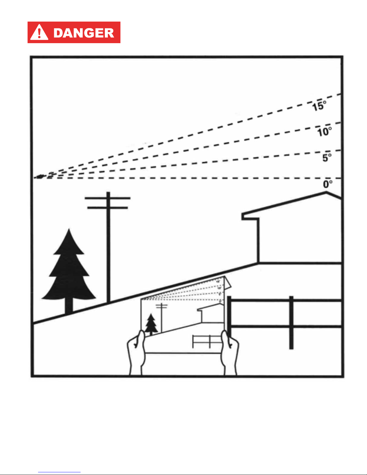
SLOPE INDICATOR
This page may be copied for personal use
outside of this manual.
Operating of this Zero Turn Mower on a Slope Exceeding 15 Degrees is unsafe and can cause upset or loss of traction resulting
in serious injury or death.
q
w
q Fold along the dashed line to measure the slope being checked.
w Align this edge with a vertical reference point, a tree, building, power pole, etc.
e Shows example of how to compare the slope with the folded edge.
Page 4

Page 5
To the Owner/Operator/Dealer
This Operator's Manual is an integral part of the safe operation of this Zero Turn Mower and must be maintained with
the Zero Turn Mower at all times. A Manual holder is provided on the Zero Turn Mower where this manual can be
properly stored. If you lose or damage this manual a free replacement manual can be obtained from an authorized
Bush Hog dealer or by down loading the manual from the Bush Hog website www.bushhog.com
BEFORE YOU START! READ, UNDERSTAND, and FOLLOW the information provided in this manual and the Engine
manual carefully to learn how to operate and service your Zero Turn Mower properly. Failure to do so could result in
personal injury to you and bystanders. All Zero Turn Mowers with moving parts are potentially hazardous. Every effort
has been made to ensure that the Zero Turn Mower is safe but operators must avoid engaging in unsafe practices
and follow the written instructions provided. The manufacturer has designed this Zero Turn Mower to be used with
all its safety equipment properly attached to minimize the chance of accidents.
SAFETY FIRST. Completely read and understand the safety section of this manual before operating this equipment.
Do not allow anyone to operate this equipment who has not fully read and understood this manual. Contact your
Dealer to explain any instructions that you do not fully understand.
The care you give your Bush Hog Zero Turn Mower will greatly determine your satisfaction with its performance and
its service life. Carefully read and follow the instructions in this manual to provide you with a thorough understanding
of your new Zero Turn Mower and its intended use and service requirements.
All references made in this manual to right, left, front, rear, top or bottom are as viewed facing the direction of forward
travel with the Zero Turn Mower.
Replacement Parts information is located in a separate Parts Manual. Bush Hog parts are made and tested to Bush
Hog specifications. Non-genuine “will fit” parts do not consistently meet these specifications. The use of “will fit” parts
may reduce Zero Turn Mower performance, void warranties, and present a safety hazard. Use genuine Bush Hog
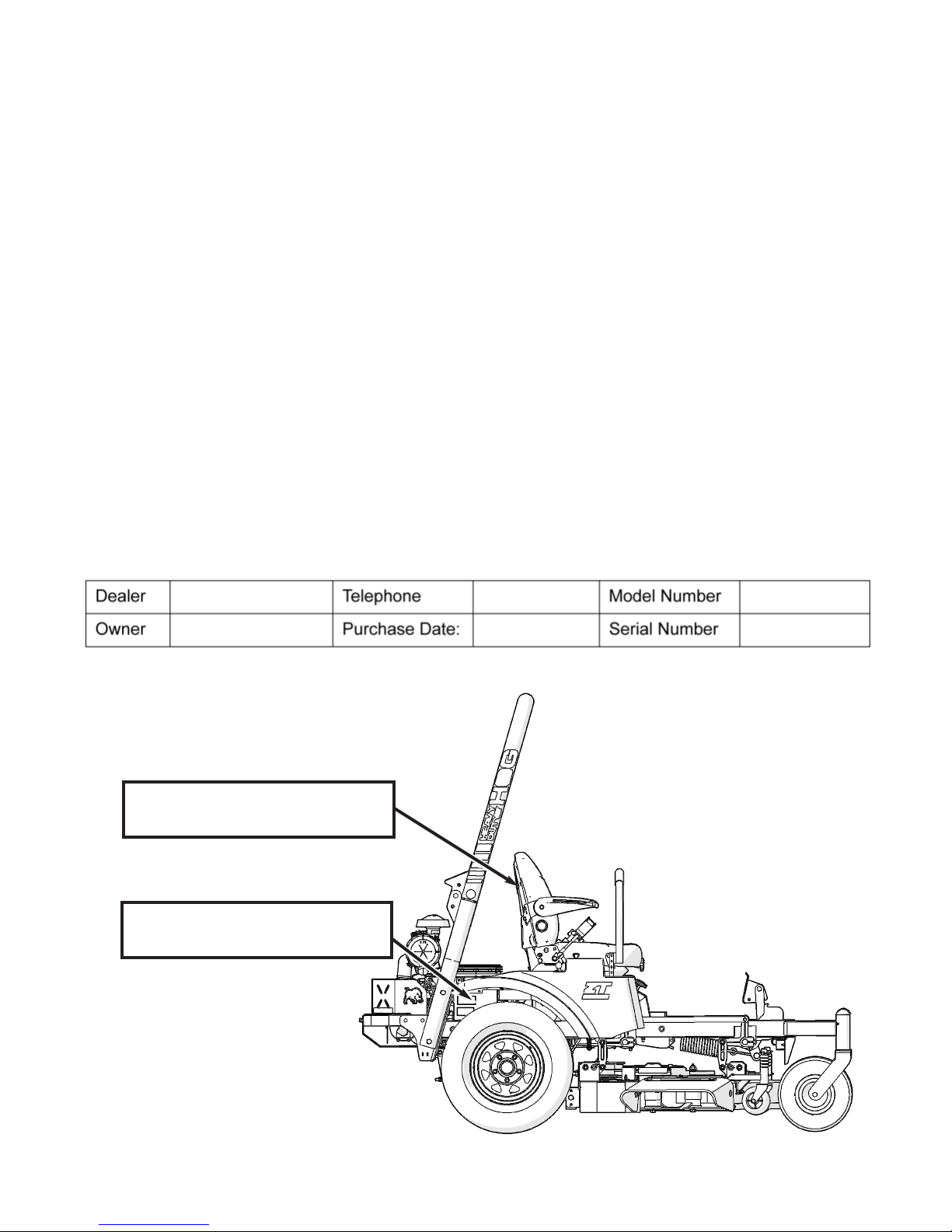
Zero Turn Mower parts for economy and safety. For future reference, record your Bush Hog product model number
and serial number.
Serial Number located on right
hand side on the frame.
Manual Holder located on back
of seat.
Page 6

LIMITED WARRANTY
Bush Hog warrants to the original purchaser of any new Bush Hog HDZ Series Zero Turn Mower purchased from an Authorized Bush Hog Dealer. This shall warranty that the Zero Turn Mower is free from defects in material and workmanship.
Warranty is a Three, (3) year Limited Warranty from the date of retail sale. (Third year parts only.)
Limited Lifetime Deck Weldment Warranty (Original Purchaser).
Engine Warranty is through the engine manufacturer.
The obligation of Bush Hog under these warranties are limited to repair or replacement of defective parts.
Replacement or repair parts installed in the equipment covered by this limited warranty are warranted for ninety (90) days
from the date of purchase of such part or the expiration of the applicable new equipment warranty period, whichever comes
later.
Warranted parts shall be provided at no cost to the user through an Authorized Bush Hog Dealer during regular hours of operation. Bush Hog reserves the right to inspect any equipment or parts which are claimed to have been defective in material
or workmanship.
DISCLAIMER OF IMPLIED WARRANTIES & CONSEQUENTIAL DAMAGES
Bush Hog’s obligation under this limited warranty, to the extent allowed by law, is in lieu of all warranties, implied or expressed,
INCLUDING IMPLIED WARRANTIES OF MERCHANTABILITY AND FITNESS FOR A PARTICULAR PURPOSE and any
liability for incidental and consequential damages with respect to the sale or use of the items warranted. Such incidental and
consequential damages shall include but not be limited to: transportation charges other than normal freight charges; cost of
installation other than cost approved by Bush Hog; duty; taxes; charges for normal service or adjustment; loss of crops or
any other loss of income; rental of substitute equipment, expenses due to loss, damage, detention or delay in the delivery
of equipment or parts resulting from acts beyond the control of Bush Hog.
THIS LIMITED WARRANTY SHALL NOT APPLY:
1. To vendor items which carry their own warranties, such as engines, tires, and tubes.
2. If the unit has been subjected to misapplication, abuse, misuse, negligence, fire or other accident.
3. If parts not made or supplied by Bush Hog have been used in connection with the unit, if, in the sole judgement of Bush
Hog such use affects its performance, stability or reliability.
4. If the unit has been altered or repaired outside of an authorized Bush Hog dealership in a manner which, in the sole
judgement of Bush Hog, affects its performance, stability or reliability.
5. To normal maintenance service and normal replacement items such as hydrostatic oil, worn blades, or to normal deterioration of such things as belts and exterior finish due to use or exposure.
6. To expendable or wear items such as belts, springs and any other items that in the company’s sole judgement is a wear
item.
NO EMPLOYEE OR REPRESENTATIVE OF BUSH HOG IS AUTHORIZED TO CHANGE THIS LIMITED WARRANTY IN
ANY WAY OR GRANT ANY OTHER WARRANTY UNLESS SUCH CHANGE IS MADE IN WRITING AND SIGNED BY
BUSH HOG’S SERVICE MANAGER, 2501 GRIFFIN AVE., SELMA, ALABAMA 36703.
Record the model number, serial number and date
purchased. This information will be helpful to your
dealer if parts or service are required.
MODEL NUMBER
SERIAL NUMBER
DATE OF RETAIL SALE
Make Certain that the retailing dealer has
registered your warranty information with
Bush Hog at time of purchase.
Page 7

DEALER PREPARATION CHECK LIST
For NEW ZERO TURN RIDING MOWER
BEFORE DELIVERING MACHINE - The following check list should be completed.
Use the Operator's Manual as a guide. Engine has been serviced.
Ground Cable connected to Battery Negative Pole.
Zero Turn Mower start code communicated to Owner.
Low oil pressure light checked for operation.
Operator interlock switches checked for operation.
Assembly completed.
All fittings lubricated.
Hydraulic Reservoirs filled to Cold Fill Line with oil.
All shields in place and in good condition.
Roll-over Protective Structure is installed and retractable seat belt functions properly.
All fasteners torqued to specifications given in Torque Chart.
All decals in place and readable. (See decal page.)
Overall condition good (i.e. paint, welds)
Parking brake checked and adjusted, if necessary.
Steering checked and adjusted, if necessary.
Check tire pressure.
Warranty information has been registered on line with Bush Hog.
Operator's manual has been delivered to owner and he has been instructed on the safe and
proper use of the Zero Turn Mower.
Dealer's Signature
Purchaser's Signature
___________________________________
THIS CHECKLIST TO REMAIN IN OWNER'S MANUAL
It is the responsibility of the dealer to complete the procedures listed
above before delivery of this Zero Turn Mower to the customer.
Page 8

Page 9

HDZ SERIES ZERO TURN MOWER
TABLE OF CONTENT
SAFETY (SECTION 1)
General Safety Instructions and Practices............................................................................1-1
Important Safety Considerations and Precautions ..............................................................1-2
Safety Instructions and Recommendations ..........................................................................1-2
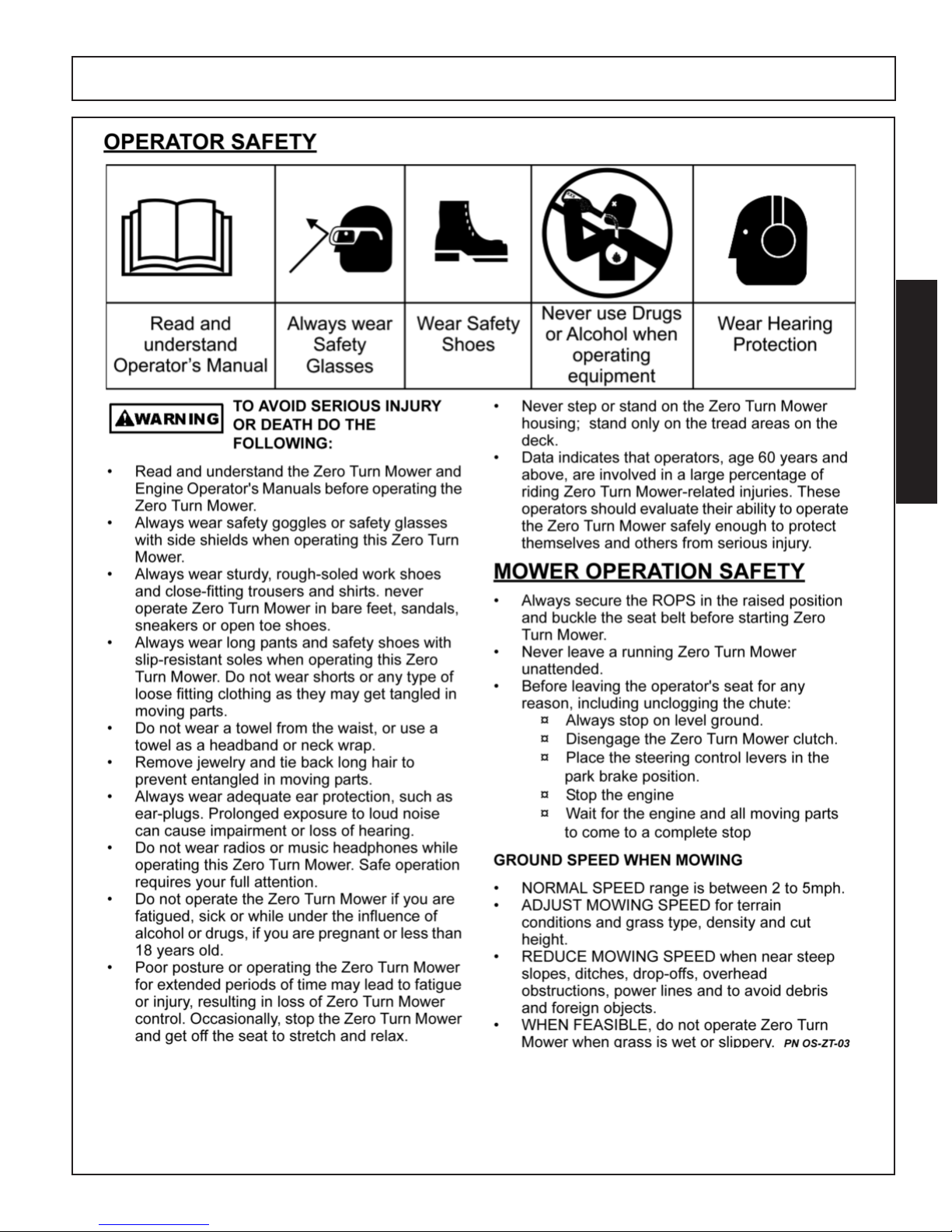
OPERATOR SAFETY................................................................................................................1-3
MOWER OPERATION SAFETY................................................................................................1-3
Ground Speed When Mowing ..................................................................................................................................1-3
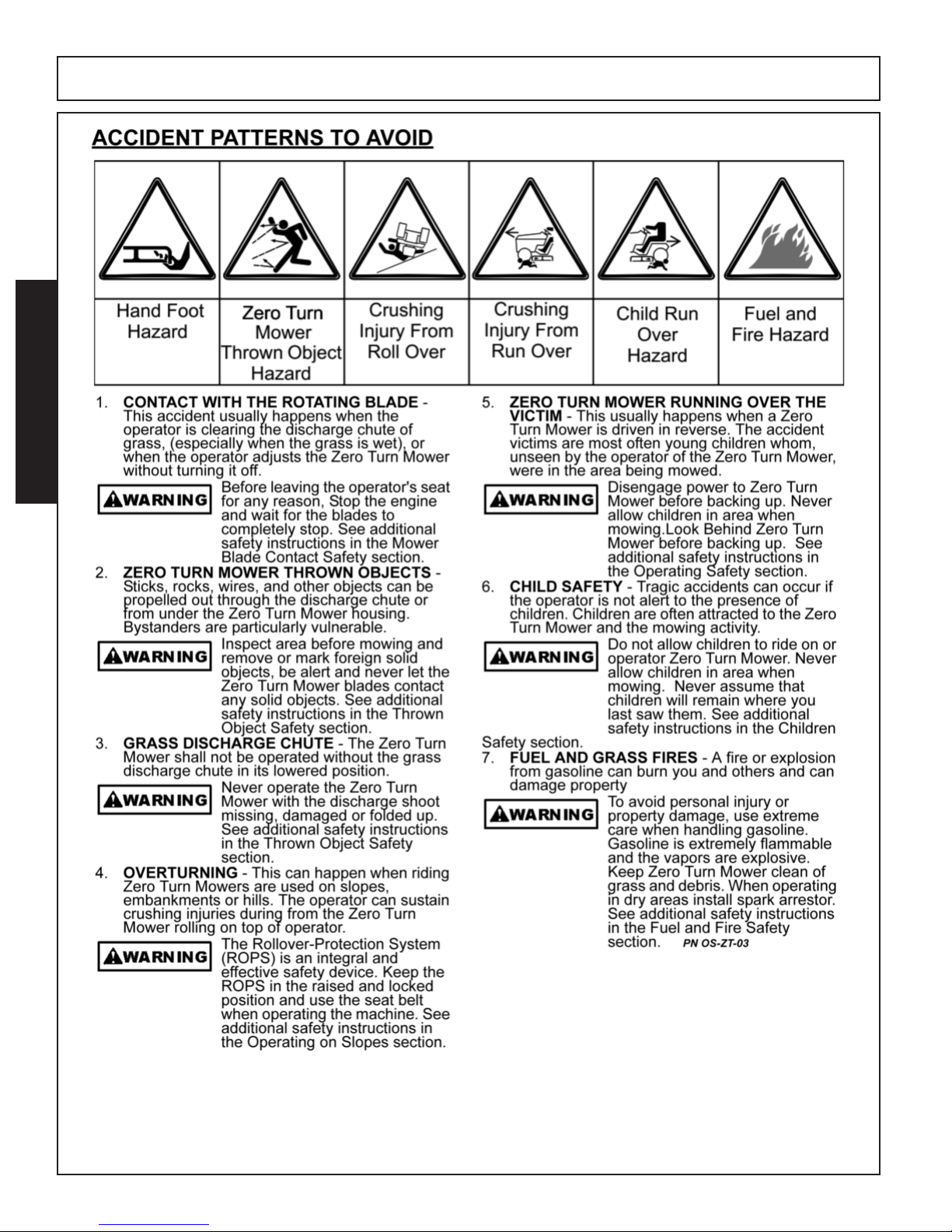
ACCIDENT PATTERNS TO AVOID...........................................................................................1-4
Contact With The Rotating Blades............................................................................................................................1-4
Mower Thrown Objects.............................................................................................................................................1-4
Grass Discharge Chute ............................................................................................................................................1-4
Over Turning.............................................................................................................................................................1-4
Mower Running Over Victim.....................................................................................................................................1-4
Child Safety ..............................................................................................................................................................1-4
Fuel and Grass Fires ................................................................................................................................................1-4
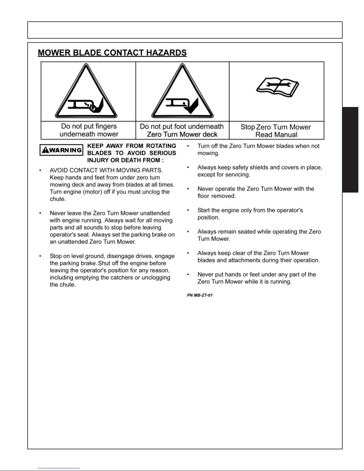
MOWER BLADE CONTACT HAZARDS...................................................................................1-5
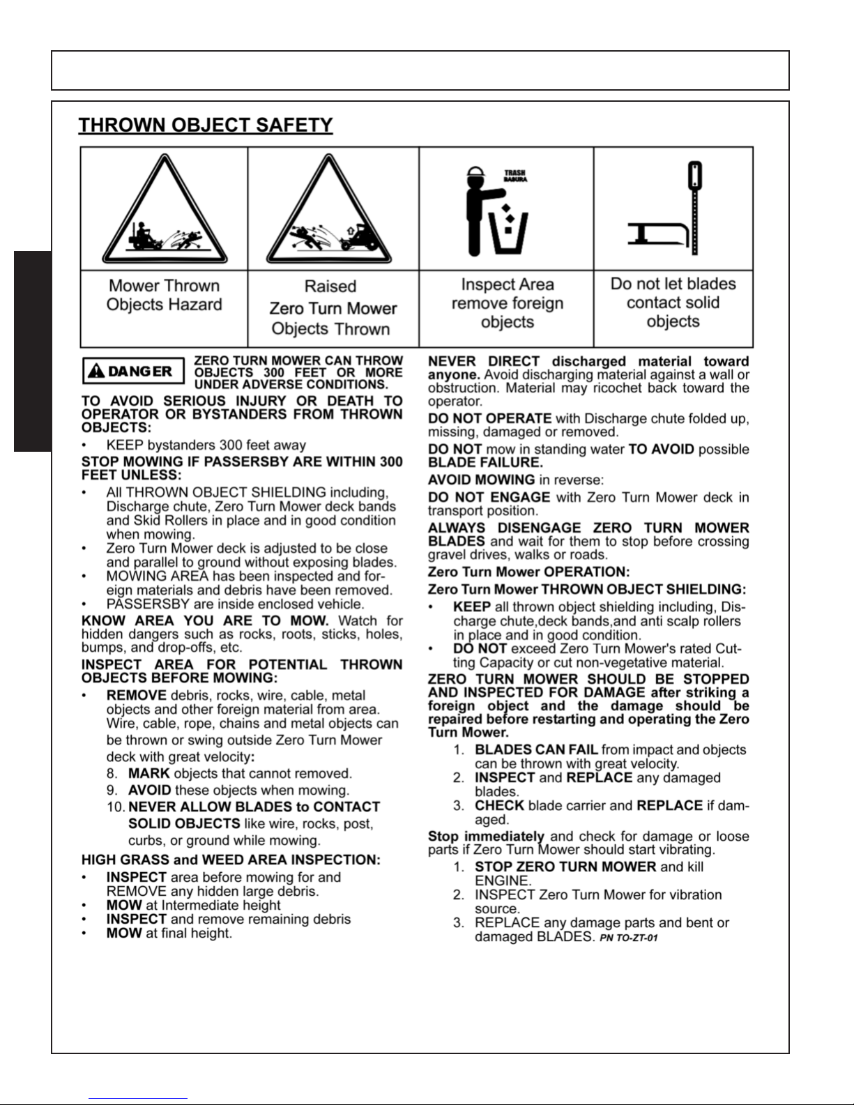
THROWN OBJECT SAFETY ....................................................................................................1-6
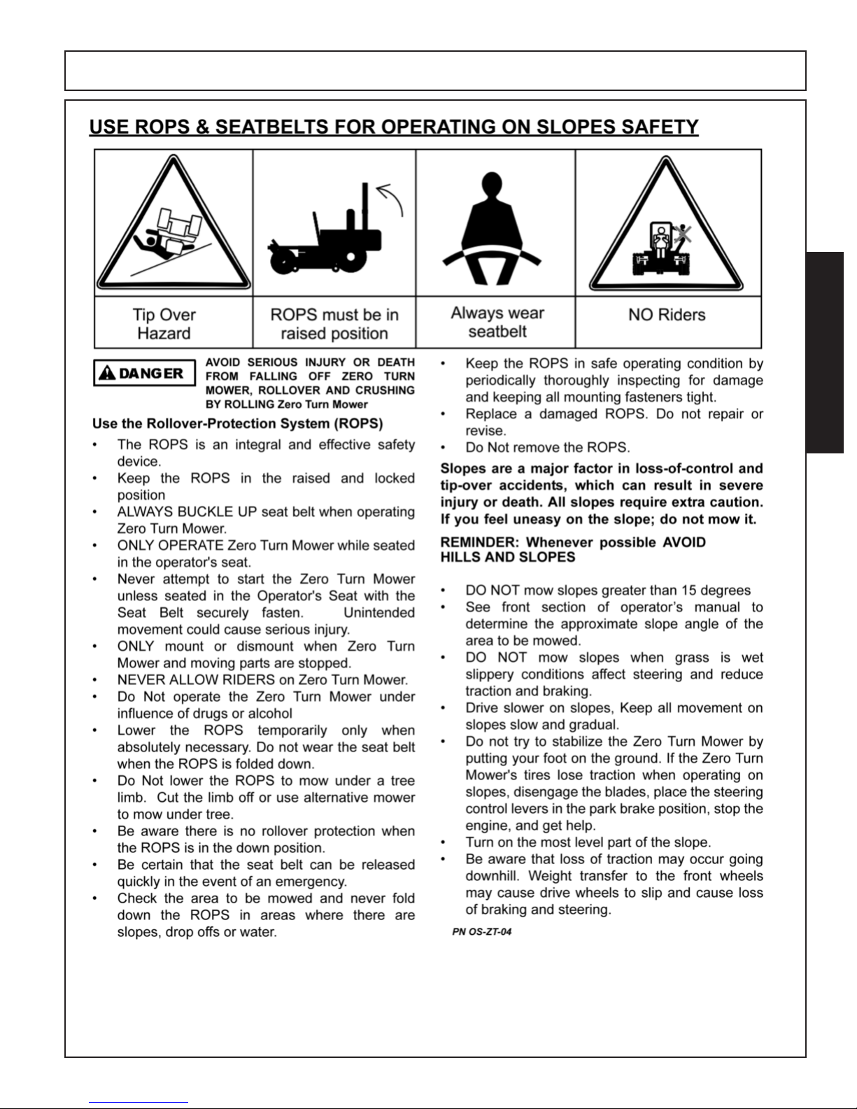
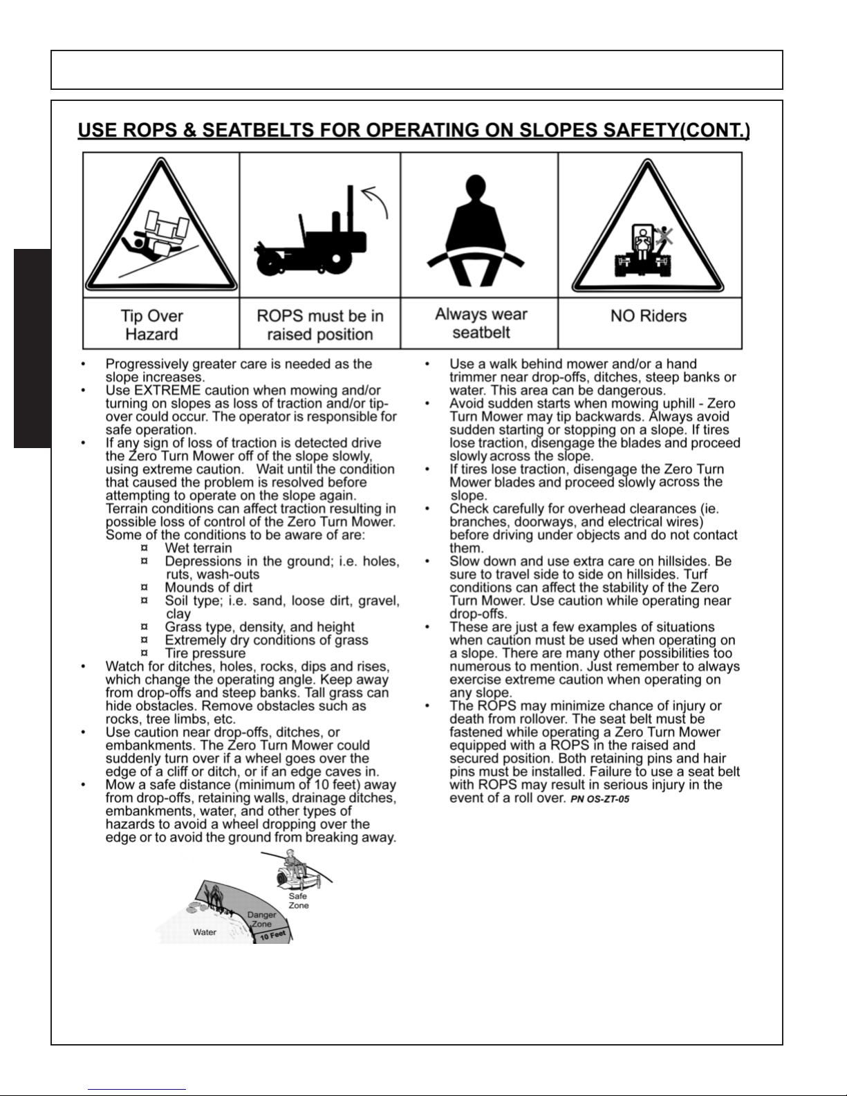
USE ROPS & SEATBELTS FOR OPERATING ON SLOPES SAFETY...........................1-7 / 1-8
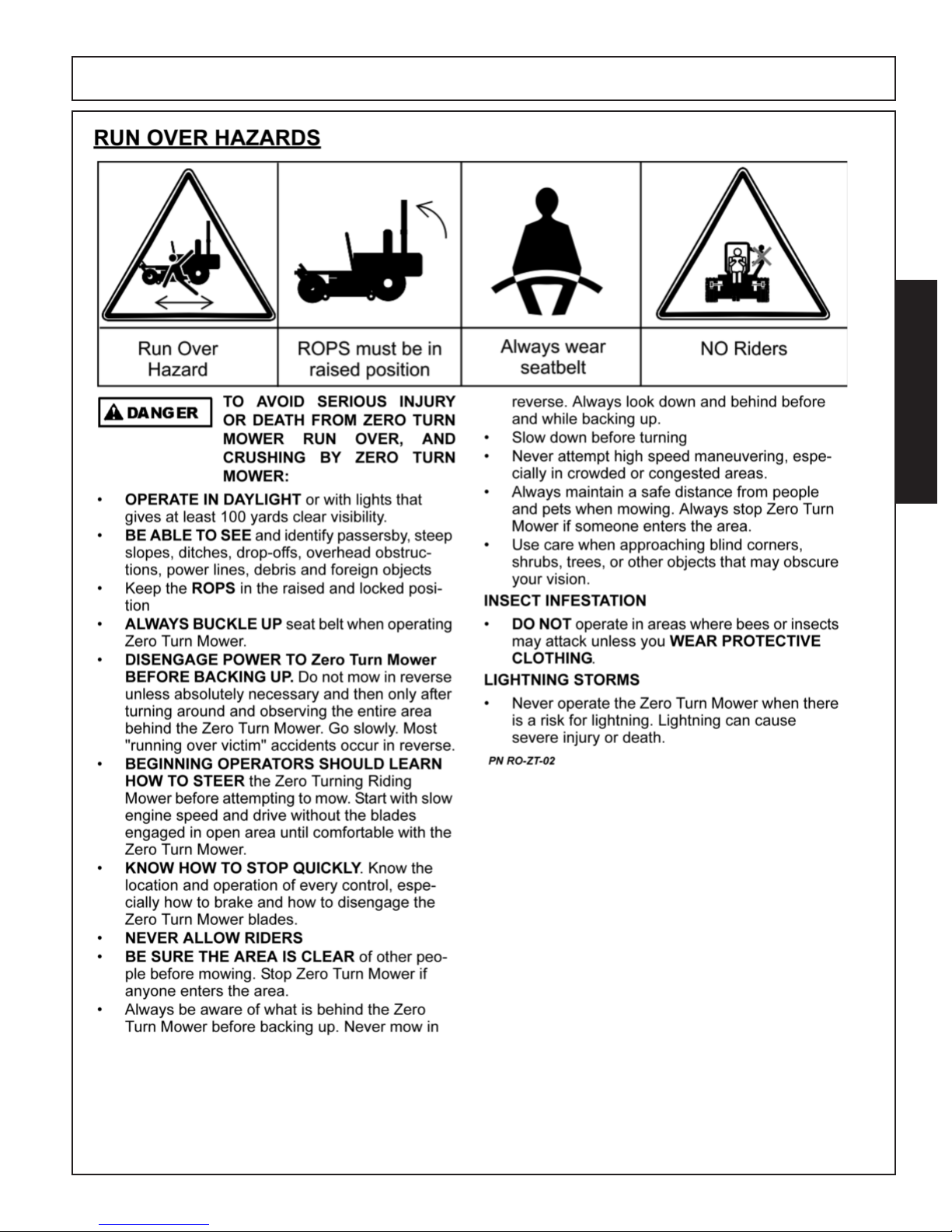
RUN OVER HAZARDS..............................................................................................................1-9
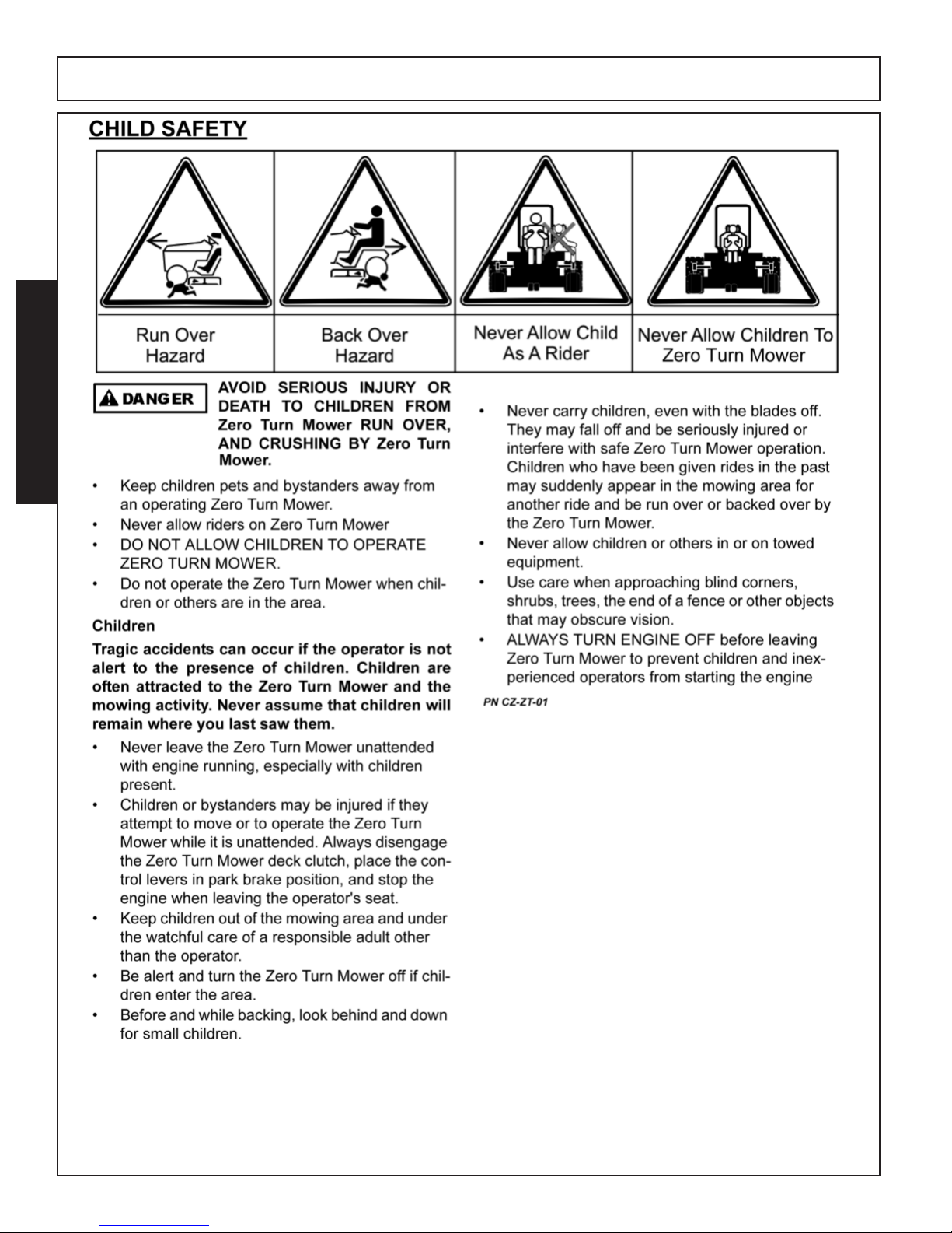
CHILD SAFETY.......................................................................................................................1-10
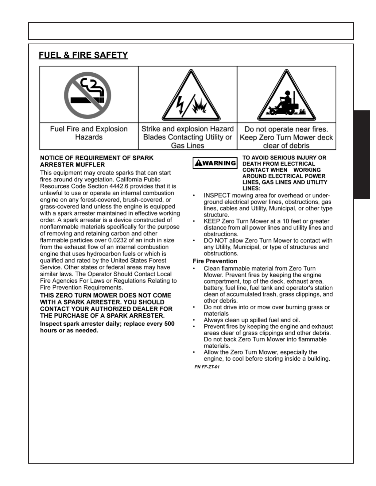
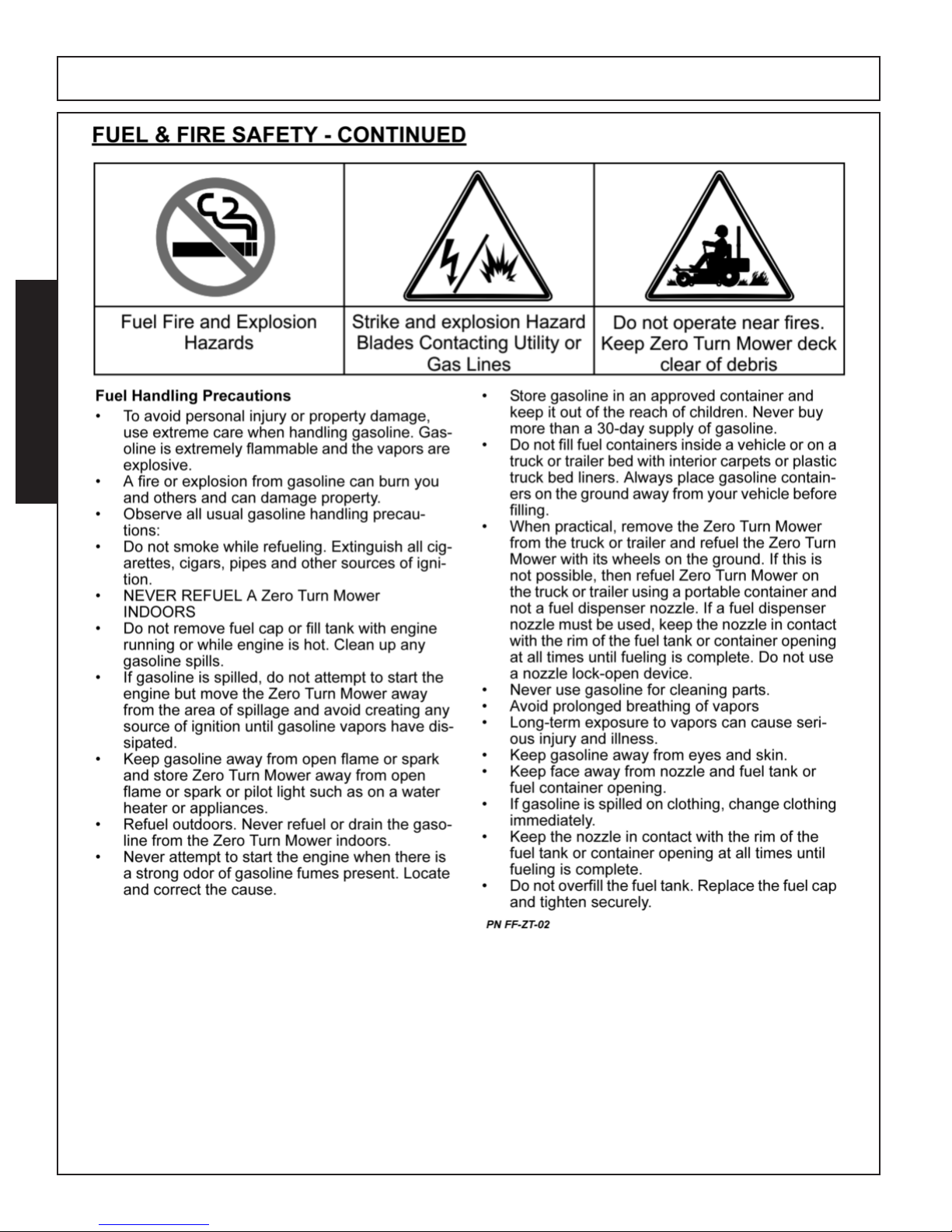
FUEL & FIRE SAFETY..................................................................................................1-11 / 1-12
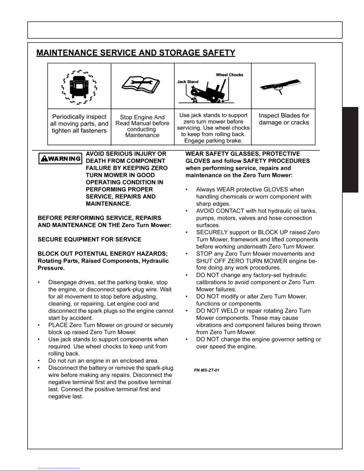
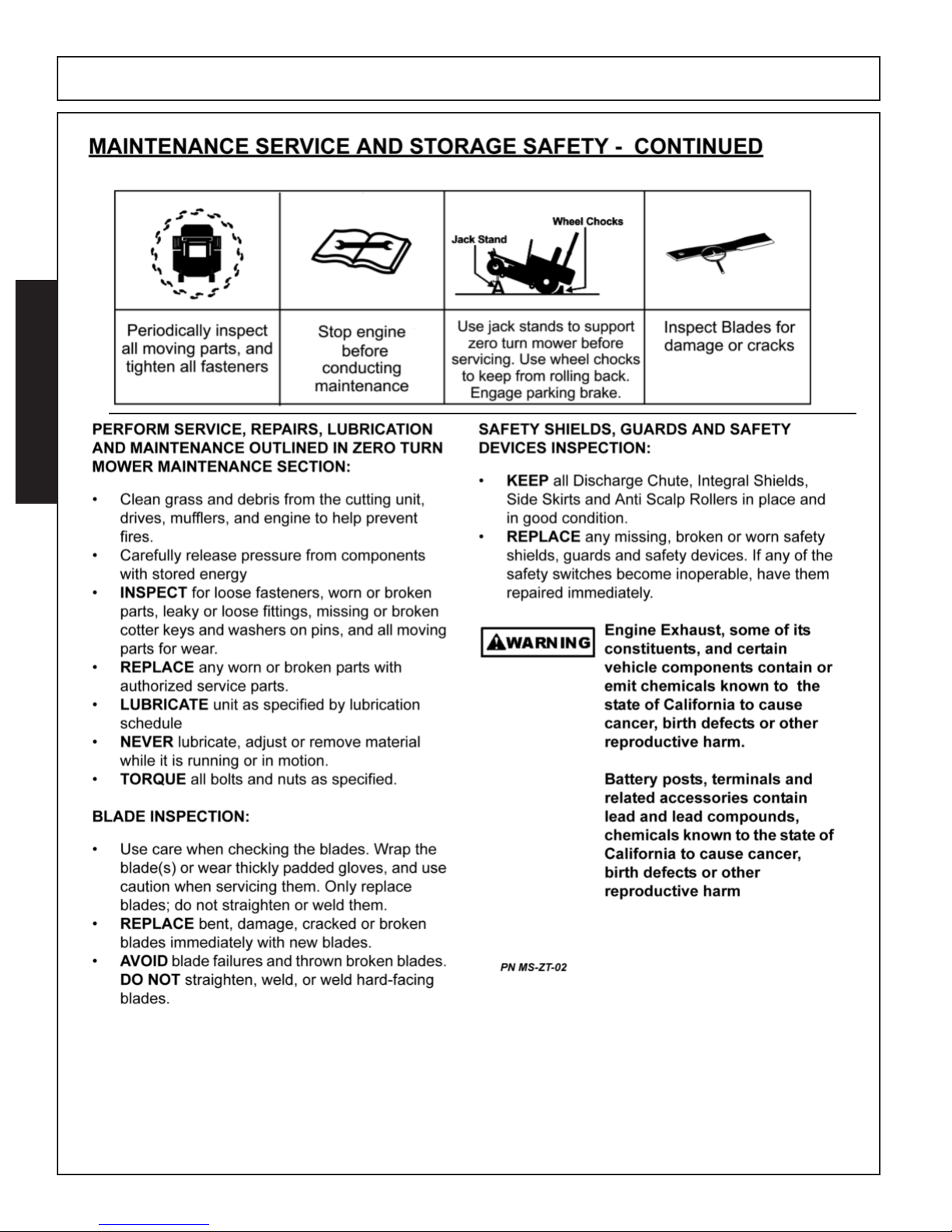
MAINTENANCE SERVICE AND STORAGE SAFETY.................................................1-13 / 1/14
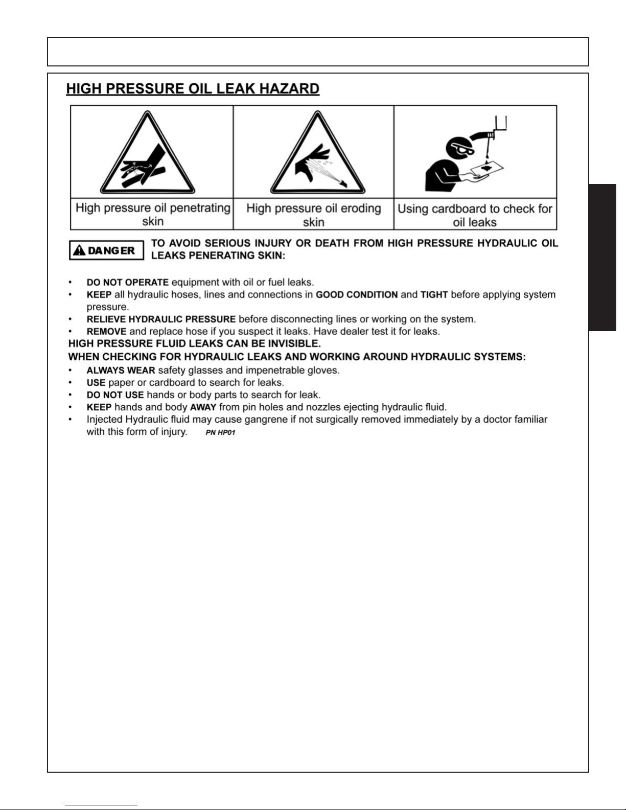
HIGH PRESSURE OIL LEAK HAZARD .................................................................................1-15
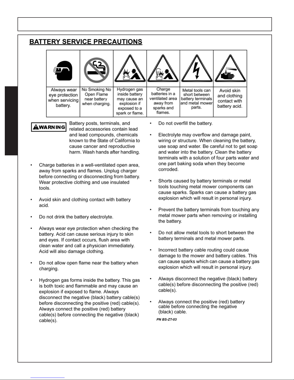
BATTERY SERVICE PRECAUTIONS.....................................................................................1-16
DRIVING AND TRANSPORTING ON PUBLIC ROADS.........................................................1-17
PARTS INFORMATION...........................................................................................................1-18
SAFETY DECAL LOCATIONS (MOWER DECK)...................................................................1-19
SAFETY DECAL LOCATIONS (POWER UNIT) .....................................................................1-20
SAFETY DECAL PICTORIALS.....................................................................................1-21 / 1/23
FEDERAL LAWS and REGULATIONS ..................................................................................1-24
INTRODUCTION (SECTION 2)
INTRODUCTION ...............................................................................................................2-1 / 2-2
SPECIFICATIONS .....................................................................................................................2-3
CONTROLS (SECTION 3)
CONTROL LOCATIONS...........................................................................................................................................3-1
CONTROL PANEL....................................................................................................................................................3-2
IGNITION SWITCH ..................................................................................................................................................3-3
PERSONALIZING YOUR KEY CODE .....................................................................................................................3-3
CHOKE and THROTTLE..........................................................................................................................................3-3
STEERING CONTROL LEVERS .............................................................................................................................3-4
PARKING BRAKE.....................................................................................................................................................3-4
USB CHARGING SOCKET ......................................................................................................................................3-4
PTO SWITCH ...........................................................................................................................................................3-5
CUTTING HEIGHT CONTROLS ..............................................................................................................................3-5
FUEL TANK and FILLER NECK ...............................................................................................................................3-5
SEAT ADJUSTMENT CONTROLS ..........................................................................................................................3-6
TRANSAXLE BYPASS CONTROLS ........................................................................................................................3-6
Page 10

OPERATION (SECTION 4)
TRAINING ...............................................................................................................4-1
BEFORE STARTING ..................................................................................................................4-1
Starting the Engine ....................................................................................................................................................4-1
Shutting Down the Engine .........................................................................................................................................4-1
STEERING..................................................................................................................................4-2
To Move Forward or Backwards ................................................................................................................................4-2
To Turn Left ................................................................................................................................................................4-2
To Turn Right..............................................................................................................................................................4-2
To Perform a Zero Turn..............................................................................................................................................4-2
OPERATING THE MOWER........................................................................................................4-2
ROPS and SEAT BELTS............................................................................................................4-3
MOWING ON SLOPES and HILLS............................................................................................4-3
MOWING NEAR WATER, DITCHES, and EMBANKMENTS ....................................................4-4
MOWING TIPS............................................................................................................................4-4
AFTER MOWING is COMPLETED ............................................................................................4-4
MOVING THE MACHINE MANUALLY.......................................................................................4-5
WEAK or DISCHARGED BATTERY..........................................................................................4-5
Jumper Cable Usage .................................................................................................................................................4-5
Starting Engine ..........................................................................................................................................................4-5
Removing Jumper Cables..........................................................................................................................................4-5
TRANSPORTING (SECTION 5)
TRANSPORTING THE MACHINE .............................................................................................5-1
Preparing to Transport ...............................................................................................................................................5-1
Loading the Machine..................................................................................................................................................5-1
Tie Down Points.........................................................................................................................................................5-1
Unloading the Machine ..............................................................................................................................................5-2
MAINTENANCE (SECTION 6)
RECOMMENDED REGULAR MAINTENANCE SCHEDULE ....................................................6-1
LUBRICATION............................................................................................................................6-2
Lubrication Points on Power Unit...............................................................................................................................6-2
Lubrication Points on Mower Deck ............................................................................................................................6-2
ENGINE MAINTENANCE...................................................................................................6-2 / 6-3
SERVICING the BATTERY.........................................................................................................6-4
Keep Battery Terminal Clean - Cleaning Battery Terminals .......................................................................................6-4
Replacing the Battery.................................................................................................................................................6-4
SAFETY SYSTEM ......................................................................................................................6-5
PARKING BRAKE ......................................................................................................................6-5
Parking Brake Adjustment..........................................................................................................................................6-5
TIRE PRESSURE .......................................................................................................................6-5
CASTER WHEELS .....................................................................................................................6-6
ANTI SCALP ROLLERS.............................................................................................................6-6
MOWER DECK V-BELT .............................................................................................................6-7
Mower Deck Belt Removal.........................................................................................................................................6-7
Mower Deck Belt Installation......................................................................................................................................6-7
Adjusting the Mower Deck Belt ..................................................................................................................................6-7
Page 11

PUMP BELT INSTALLATION.....................................................................................................6-9
CUTTING BLADE MAINTENANCE ...........................................................................................6-9
Blade Removal...........................................................................................................................................................6-9
Inspect Blades ...........................................................................................................................................................6-9
Sharpening Blades...................................................................................................................................................6-10
Installing Blades.......................................................................................................................................................6-10
ADJUSTING the MOWER DECK.............................................................................................6-10
Leveling the Deck ....................................................................................................................................................6-10
TRANSAXLE MAINTENANCE.................................................................................................6-11
Fluid and Filter Change Procedure ..........................................................................................................................6-11
Purging Procedures .................................................................................................................................................6-12
CONSOLE MAINTENANCE ...........................................................................................6-13- 6-15
General Care ...........................................................................................................................................................6-14
Bypass or Failed Safety Interlock Switch Detection.................................................................................................6-14
Service Alerts ...........................................................................................................................................................6-14
Alarms......................................................................................................................................................................6-14
Console Diagnostic Codes.......................................................................................................................................6-15
STORAGE (SECTION 7)
WINTER STORAGE ...................................................................................................................7-1
Preparing the Machine for Storage ............................................................................................................................7-1
New Season Preparation ...........................................................................................................................................7-1
TROUBLE SHOOTING (SECTION 8) .....................................................................8-1
TECHNICAL DATA (SECTION 9)
MAIN WIRING HARNESS with FUSE LOCATIONS..................................................................................................9-1
MAIN WIRING HARNESS SCHEMATIC ...................................................................................................................9-2
ENGINE ADAPTOR HARNESS for BRIGGS & STRATTON ENGINE ......................................................................9-3
ENGINE ADAPTOR HARNESS FOR KAWASAKI ENGINES ...................................................................................9-4
ENGINE ADAPTOR HARNESS FOR KOHLER ENGINES.......................................................................................9-5
TORQUE SPECIFICATIONS .....................................................................................................................................9-6
SERVICE and MAINTENANCE RECORDS ..............................................................................................................9-7
Notes Page ................................................................................................................................................................9-8
Page 12

Page 13

SAFETY
SECTION 1
Page 14

Page 15
SAFETY
SAFETY
HDZ ZT 01/17 Safety Section 1-1
© 2016 Alamo Group Inc.
Page 16
SAFETY
SAFETY
HDZ ZT 01/17 Safety Section 1-2
© 2016 Alamo Group Inc.
Page 17
SAFETY
SAFETY
HDZ ZT 01/17 Safety Section 1-3
© 2016 Alamo Group Inc.
Page 18
SAFETY
SAFETY
HDZ ZT 01/17 Safety Section 1-4
© 2016 Alamo Group Inc.
Page 19
SAFETY
SAFETY
HDZ ZT 01/17 Safety Section 1-5
© 2016 Alamo Group Inc.
Page 20
SAFETY
SAFETY
HDZ ZT 01/17 Safety Section 1-6
© 2016 Alamo Group Inc.
Page 21
SAFETY
SAFETY
HDZ ZT 01/17 Safety Section 1-7
© 2016 Alamo Group Inc.
Page 22
SAFETY
SAFETY
HDZ ZT 01/17 Safety Section 1-8
© 2016 Alamo Group Inc.
Page 23
SAFETY
SAFETY
HDZ ZT 01/17 Safety Section 1-9
© 2016 Alamo Group Inc.
Page 24
SAFETY
SAFETY
HDZ ZT 01/17 Safety Section 1-10
© 2016 Alamo Group Inc.
Page 25
SAFETY
SAFETY
HDZ ZT 01/17 Safety Section 1-11
© 2016 Alamo Group Inc.
Page 26
SAFETY
SAFETY
HDZ ZT 01/17 Safety Section 1-12
© 2016 Alamo Group Inc.
Page 27
SAFETY
SAFETY
HDZ ZT 01/17 Safety Section 1-13
© 2016 Alamo Group Inc.
Page 28
SAFETY
SAFETY
HDZ ZT 01/17 Safety Section 1-14
© 2016 Alamo Group Inc.
Page 29
SAFETY
SAFETY
HDZ ZT 01/17 Safety Section 1-15
© 2016 Alamo Group Inc.
Page 30
SAFETY
SAFETY
HDZ ZT 01/17 Safety Section 1-16
© 2016 Alamo Group Inc.
Page 31

SAFETY
SAFETY
© 2016 Alamo Group Inc.
HDZ ZT 01/17 Safety Section 1-17
Page 32

SAFETY
HDZ ZT 01/17 Safety Section 1-18
SAFETY
© 2016 Alamo Group Inc.
Page 33

SAFETY
SAFETY
© 2016 Alamo Group Inc.
HDZ ZT 01/17 Safety Section 1-19
Safety Decal Location Mower Deck
ITEM PART NO. QTY. DESCRIPTION
1 D914 2 Danger Decal - Rotating Blades
2 D646 1 Warning Decal - Shield Missing Decal
3 D916 1 Danger Decal - Do Not Mow without Discharge Chute in Place
4 D917 1 Danger Decal - Thrown Object Hazard
5 D918 2 Warning Decal - Keep Shields In Place
6 50077946 1 Installation Decal, Mower Belt
7 D943 1 Not a Step Decal
Page 34

SAFETY
SAFETY
© 2016 Alamo Group Inc.
HDZ ZT 01/17 Safety Section 1-20
Safety Decal Location Power Unit
ITEM PART NO. QTY. DESCRIPTION
1 D859 1 Warning - Use Genuine Bush Hog Parts
2 D919 1 Warning - Crushing Hazard
3 D920 1 Instruction - Maintain ROPS (English)
4 D921 1 Warning - Hot Surface
5 D922 1 Instruction - Maintain ROPS (Spanish)
6 D923 1 Warning - Crushing Hazard
7 D924 1 Caution - Hearing Protection
8 D925 1 Caution - Avoid Equipment Fires (Spanish)
9 D926 1 Danger - Avoid Injury to Children
10 D927 1 Caution - Help Avoid Bodily Injury (Spanish)
11 D928 1 Caution - Help Avoid Bodily Injury (English)
12 D929 1 Danger - Avoid Tip-Over
13 D931 1 Caution - Avoid Equipment Fires (English)
e
w
w
t
y
u
1@
1@
i
q
o
1!
1#
1)
Page 35

SAFETY
SAFETY
© 2016 Alamo Group Inc.
HDZ ZT 01/17 Safety Section 1-21
Safety Decal Pictorials
Page 36

HDZ ZT 01/17 Safety Section 1-22
Safety Decal Pictorials
SAFETY
SAFETY
© 2016 Alamo Group Inc.
Page 37

SAFETY
SAFETY
© 2016 Alamo Group Inc.
Safety Decal Pictorials
HDZ ZT 01/17 Safety Section 1-23
Page 38

SAFETY
SAFETY
© 2016 Alamo Group Inc.
HDZ ZT 01/17 Safety Section 1-24
Safety Decal Pictorials
Page 39

SAFETY
SAFETY
HDE ZT 10/16 Safety Section 1-25
© 2016 Alamo Group Inc.
Page 40

Page 41

INTRODUCTION
SECTION 2
Page 42

Page 43

INTRODUCTION
INTRODUCTION
HDZ ZT 01/17 Introduction Section 2-1
© 2016 Alamo Group Inc.
We are pleased to have you as a Bush Hog customer. Your Bush Hog Zero Turn Riding Mower
has been carefully designed with care and built with quality materials by skilled workers to give
maximum service with minimum down time. This manual is provided to give you the necessary
operating and maintenance instructions for keeping your Zero Turn Mower in top operating condition. Careful use and timely service saves extensive repairs and costly down time losses.
Please read this manual thoroughly. Understand what each control is for and how to use it. No
shielding is 100% effective in preventing thrown objects. The possibility of injury and property
damage from this hazard can be substantially reduced by selecting proper shielding, maintaining
the Zero Turn Mower and shielding in good operational condition, inspecting the area for foreign
debris before mowing, and operating the Zero Turn Mower at a minimum cutting height, Keep
unprotected persons at a minimum distance of 300 feet from the Zero Turn Mower at all times
during operation. Safety is of primary importance to the owner/operator and to the manufacturer.
Observe all safety precaution decals on the Zero Turn Mower and noted throughout the manual
for safe operation of Zero Turn Mowers. If any assistance or additional information is needed,
contact your authorized Bush Hog dealer. The owner/operator/dealer should know and understand the Safety Messages before assembly and be aware of the hazards of operating this Zero
Turn Mower during assembly, use, and maintenance. The Safety Alert Symbol combined with
a Signal Word, as seen below, is intended to warn the owner/operator of impending hazards
and the degree of possible injury faced when operating this Zero Turn Mower.
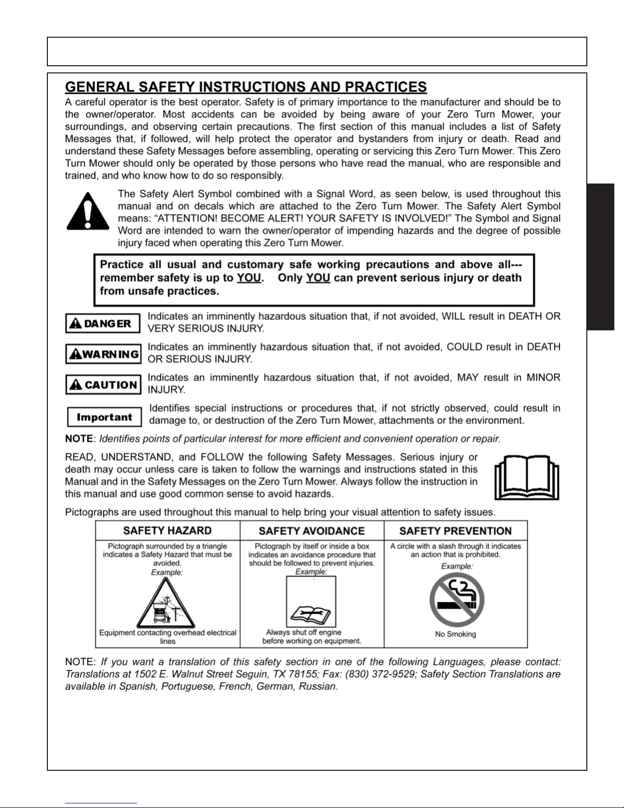
! DANGER
! WARNING
! CAUTION
IMPORTANT!
Indicates an imminently hazardous situation that, if not avoided, WILL result
in DEATH OR VERY SERIOUS INJURY.
Indicates an imminently hazardous situation that, if not avoided, COULD result in DEATH OR SERIOUS INJURY.
Indicates an imminently hazardous situation that, if not avoided, MAY result
in MINOR INJURY.
Identifies special instructions or procedures that, if not strictly observed, could
result in damage to, or destruction of the Zero Turn Mower, attachments or
the environment.
Page 44

INTRODUCTION
INTRODUCTION
HDZ ZT 01/17 Introduction Section 2-2
© 2016 Alamo Group Inc.
The Bush Hog Zero Turn is intended for use on lawns and other frequently
maintained areas where a smooth, even cut is desired and superior maneuverability is needed. The Power Unit consists of a Briggs & Stratton,
Kawasaki, or Kohler twin cylinder engine. The engine has a pressurized oil
lubrication system with spin-on type filter, fused electronic ignition, electric
start and the Zero Turn has a 9 gallon fuel system.
Two hydrostatic transaxles are used for propelling and steering. The
Transaxles are belt driven by the engine output shaft. One lever for each drive controls both speed
and direction. This independent control of each drive wheel coupled with continuously variable
speed selection gives the Zero Turn mower exceptional maneuverability.
The Zero Turn Mower Deck is available in 61” or 73” cutting widths. The Zero Turn Mower has
three cutting blades, driven by an electromagnetic clutch through a single v-belt.
Front, rear, left and right are determined by the normal direction of travel, the same as driving an
automobile.
Page 45

INTRODUCTION
INTRODUCTION
HDZ ZT 01/17 Introduction Section 2-3
© 2016 Alamo Group Inc.
SPECIFICATIONS
HDZ Series Zero Turn Mower
MODEL ENGINE CUTTING WIDTH
HDZ2661VG ........................................26 HP Briggs and Stratton VanGuard ........................................ 61” Deck
HDZ2761CV.........................................27 HP Kohler Command Pro ..................................................... 61” Deck
HDZ2761FX .........................................27 HP Kawasaki FX850 ..............................................................61” Deck
HDZ2773CV.........................................27 HP Kohler Command Pro ......................................................73” Deck
HDZ3161FX .........................................31 HP Kawasaki FX921 ..............................................................61” Deck
HDZ3173FX .........................................31 HP Kawasaki FX921 ..............................................................73” Deck
HDZ3273VG ........................................32 HP Briggs and Stratton VanGuard ........................................ 73” Deck
CONTROLS.........................................Electronic Control Module with Keyless Start, System Monitoring and
Soft Start PTO Engage
PTO......................................................Electromagnetic Clutch rated at 200 FT/LBS
FUEL CAPACITY.................................9 Gallons (87 Octane Unleaded Gasoline)
TRANSAXLES.....................................(2) Hydro-Gear ZT5400 Hydrostats
TIRES ..................................................Front - 13 x 6.5 - 6
Rear - 24 x 12 - 12 (Selection of Turf Tire or Bar Tire)
TREAD WIDTH....................................50”
HEIGHT to TOP OF SEAT BACK .......47” Non Suspension Seat / 51” Full Suspension Seat
STEERING...........................................Dampened Twin Lever, Adjustable Fore, Aft and Vertical
SPEED.................................................Infinitely Variable 0-8 mph Forward, 0-4 mph Reverse
DECK SPECIFICATIONS
CUTTING WIDTHS...........................................................61” .......................73”
OVERALL WIDTH (CHUTE DOWN)................................75” .......................89”
BLADES (Standard) ........................................................(3) 21” Uplift .........(3) 25” Uplift
CUTTING HEIGHTS ............................1-1/2” to 5-1/2” Adjustable in 1/4” Increments
DECK CONSTRUCTION.....................7 Gauge reinforced steel
SAFETY
Integrated Operator Presence Controls
2-7/8” Round Tube ROPS
Seat Belts
Page 46

Page 47

CONTROLS
SECTION 3
Page 48

Page 49

CONTROLS
CONTROLS
HDZ ZT 01/17 Controls Section 3-1
© 2016 Alamo Group Inc.
CONTROL LOCATIONS
1. Transaxle Bypass Linkage
2. Fuel Cap
3. Steering Control Levers
4. Parking Brake Lever
5. Seat Adjusting Lever
6. Deck Lift Pedal
7. Deck Height Adjusting Knob
8. Start / Stop Button
9. Mower PTO Switch
10. USB Charging Socket
11. Choke
12. Engine Throttle Control
Page 50

CONTROLS
CONTROLS
HDZ ZT 01/17 Controls Section 3-2
© 2016 Alamo Group Inc.
CONSOLE
q
w
e
r
t
y
u
i
o
1)
1!
1@
1#
1$
1%
ITEM DESCRIPTION FUNCTION
q
Engine Start/Stop Button Powers Engine ON / Powers Engine OFF.
w Key Code Buttons Powers up Console by entering Key Code and enables specific functions
as starting /stopping engine, engaging PTO.
e OK to Start Indicator Light Glows Green when safe to start engine, Red when unsafe.
r PTO Indicator LED Glows Red to indicate PTO is engaged.
t Steering Lever Indicator LED Glows Reds when Steering Levers are not in Neutral position during startup
y Parking Brake LED Glows Red if Parking Brake not set during startup.
u Operator Position Indicator Glows Red if Operator is not in seat.
i Low Oil Indicator LED Alerts Operator when Engine oil is low.
o Fuel Level Indicator LED Alerts Operator when Fuel is low.
1) PTO Switch Engages / Disengages Mower Blades.
1! LCD Display Indicates Hours, Service Alerts, Engine RPM, and Voltage.
1@ Head Light ON/OFF Switch Turns Head Lights On and Off.
1# Hour Meter Switch Total Accumulated Engine Hours.
1$ Tachometer / Voltage Switch Switch between Engine RPM or System Voltage.
1% Service Engine Indicator Indicates engine Oil Change is needed. Press down and hold for 6-9 sec-
onds to reset after Oil Change.
NOT
USED
Page 51

CONTROLS
CONTROLS
HDZ ZT 01/17 Controls Section 3-3
© 2016 Alamo Group Inc.
Ignition Switch
Choke and Throttle
The Ignition Switch is keyless and is the Red Button on
the Console located on the right hand side of the Zero
Turn Mower. This controls starting and stopping the engine.
A 4 digit code must be entered before the engine can be started.
This code will be supplied by the dealer at the time
the purchaser takes ownership of the Zero Turn
Mower. A code is programmed at the factory for use until
the owner changes it to his personal code.
It is recommended that the owner personalize the
code as soon as possible after taking ownership of
the Zero Turn Mower.
See Personalizing Your Key Code.
PERSONALIZING YOUR KEY CODE
1. Record your new Key Code (1-12 digits) for safe keeping. NOTE: Only a dealer service call can reset a for
-
gotten code.
2. Engine must be stopped and console unlocked (using
the original code that comes with the Zero Turn
Mower) and the PTO Switch down (OFF).
3. Hold KEY CODE BUTTONS 1 & 2 simultaneously for
three seconds until the display shows “CHNGE”
“CODE” followed by a blank screen.
4. Enter the new key code into the console. If more than
12 digits are used the display shows “FULL”
NOTE: The display always shows the 5 most recently
entered digits.
5. After entering the new code, pull the PTO Switch up.
If the new code is unusable, the display will show
“BAD” “CODE”. If this occurs push the PTO switch
down and return to step 1 and try a different code.
NOTE: If user does not enter a code and pulls the PTO
switch up the display shows “EMPTY” “CODE”.
IGNITION
SWITCH
CHOKE
The Choke provides a richer fuel mixture to the engine
to assist on cold starts. Pull the choke up to engage and
once the engine starts push down to disengage.
THROTTLE
The Throttle controls the engine speed and blade speed
when blades are engaged. To increase the engine and
blade speeds push the Throttle forward and to decrease
the speeds push the throttle toward the back. For best
mowing performance run the engine at full throttle and
control your ground speed with the Steering levers.
THROTTLE
LEVER
CHOKE
6. If the new code is usable, the console prompts the
user to re-enter the code again by displaying: ENTER”
“CODE” “AGAIN”. Re-enter the code used in step 4,
then push the PTO switch down
.
7. The console confirms that the two key codes entered
in step 4 and 6 match. If they do match, the console
saves the new unlock code and displays “SAVED”
“CODE” before returning to the previous display
mode. If they do not match the console displays “NO”
“MATCH” and the user must return to step 1.
NOTE: If no input is received for 10 seconds the console displays”TIME” “OUT” before returning to the
previous display mode, retaining the previous unlock
code.
RECORD YOUR PERSONALIZED KEY CODE HERE
IMPORTANT!
Page 52

CONTROLS
CONTROLS
HDZ ZT 01/17 Controls Section 3-4
©
2016 Alamo Group Inc.
Steering Control Levers
Steering Control Levers control the direction and speed
of the Zero Turn Mower in both forward and reverse
travel. Turning is controlled by pushing one lever forward
and pulling the opposite lever backward or to the neutral
position.
Moving the levers forward equally will cause the Zero
Turn Mower to travel forward in a straight line. Moving
the levers backward equally causes the Zero Turn
Mower to travel in reverse. The further the levers are
moved forward or backward increases the speed of
travel in that direction.
THE ZERO TURN MOWER WILL
TURN VERY RAPIDLY IF ONE
STEERING LEVER IS MOVED MUCH FURTHER
FORWARD THAN THE OTHER.
Moving the right hand lever forward and the left hand
lever to the neutral position turns the Zero Turn Mower
left. Moving the left hand lever forward and the right hand
lever to the neutral position turns the Zero Turn Mower
to the right.
Moving the right hand lever forward and the left hand
lever backward the Zero Turn Mower will achieve a zero
turn to the left. Moving the left hand lever forward and
the right hand lever backward achieves a zero turn to the
right. These maneuvers should be done with extra
care at a slow speed when turning.
The Parking Brake is located on the left side of the Zero
Turn Mower. To set the brake pull the lever up and push
down to release. When engaging the brake the Zero Turn
Mower must be completely motionless. Always set the
Parking Brake before dismounting the Zero Turn Mower
and always release the brake before putting the Zero
Turn Mower into operation.
NOTE: If the Parking Brake is not set in the Park position when starting, the engine will not start and the
Parking Brake LED will be lit on the console. Release
the brake after the engine has started.
NOTE: Applying the parking brake while in forward
or reverse travel and the Steering Levers in the operating position will stop the engine and could do
possible damage to the Hydrostat Drives.
USB Charging Socket
During Zero Turn Operation, the USB Charging Socket
provides USB charging from 2 ports. The ports are 2.1
AMP - 5 Volt and a 1 AMP - 5 Volt.
Parking Brake
! WARNING
Parking Brake
Parking Brake
Lever
Lever
Page 53

CONTROLS
CONTROLS
HDZ ZT 01/17 Controls Section 3-5
© 2016 Alamo Group Inc.
PTO Switch
The PTO Switch is located on the Console and is Yellow
in color.
To engage the Zero Turn mower blades pull the PTO
Switch switch up and to disengage push the switch down.
NOTE: The PTO Switch should only be engaged when
the engine is running and the steering levers are in
the Neutral position. The Zero Turn Mower will not
start if the PTO Switch is pulled up prior to starting
the Zero Turn Mower. It must always be in the OFF
(Down) position to start.
The Fuel Tank is located under the operators seat and
the Filler Neck is located on the left hand side toward the
rear of the seat. The Fuel Cap is tettered to the tank to
avoid dropping when refueling the Zero Turn Mower.
Gasoline is highly flammable. The engine and exhaust system become
very hot during operation.
Allow engine and exhaust system to cool down before refueling the Zero Turn Mower.
Use CAUTION and only fill outdoors.
Fill to the bottom of the filler neck (DO NOT OVER FILL).
Do not fuel the Zero Turn Mower near an open flame.
Clean away any spilled fuel after re-fueling and before
re-starting the Zero Turn Mower.
Check the gas fill cap often for damage to gasket. If damaged replace the fill cap.
The engine is designed to operate on 87 Octane unleaded gasoline.
Damage to the engine may occur if E85 Alcohol based
fuel or Methanol fuel is used.
The Cutting Height is controlled by pushing the Foot Control Pedal all the way forward and turning the Height Adjusting knob to the desired cutting height and aligning
with the indicator point on panel. Release the pressure
on the Foot Control Pedal until it stops at the set cutting
height.
PTO
Switch
Cutting Height Controls
Fuel Tank and Filler Neck
IMPORTANT: To maintain an even cutting
height, all tires must have equal air pressure
of 15 psi /103kPa / 1bar.
Filler
Neck
&
Fuel
Cap
! WARNING!
IMPORTANT: Always raise the Zero Turn
Mower Deck to the highest position and disengage blades when transporting.
Foot Control Pedal
Height Control Knob
Page 54

CONTROLS
CONTROLS
HDZ ZT 01/17 Controls Section 3-6
© 2016 Alamo Group Inc.
Seat Adjustment Controls
Transaxle Bypass Control
1
2
3
4
5
FULL SUSPENSION SEAT
1. The Weight Adjustment Knob lets you set a personalized suspension setting.
2. The Backrest Angle Adjustment Knob.
3. Arm Rest Height adjustment (raise arm rest to access
adjustment knobs).
4. Seat Slide allows 6” of fore and aft adjustment.
5. Lumbar Support Adjustment Knob.
The seat is shaped to increase air flow so that you stay
more comfortable on hot days
NOTE: Do not push, pull, or tow this Zero Turn Mower
without first releasing the hydraulic pressure in the Integrated Transaxles.
The Transaxle hydraulic fluid Bypass Control Valves are
located on the front / inside of the transaxle on the underside of the Zero Turn Mower as shown above.
Bypass Control Valves are close to
the muffler and other HOT parts.
NEVER
attempt to manipulate the Bypass Control
Valves while the engine is running.
To prevent burn injury or physical injury turn the Zero
Turn Mower off and allow for a cool down period before
changing the Bypass Control Valves.
To move the zero turn mower without
engine power (engine off) the Bypass Control Valve must be placed in the
BYPASS position and parking brake off.
To relieve the hydraulic pressure on the transaxles, locate the Bypass Control Valve on the transaxle. Insert a
large flat blade screw driver into the slot and turn the control 90 degrees to the BYPASS position. This allows the
zero turn mower to be moved around without engine
power.
NOTE:
The Transaxle Bypass Control Valves must be
placed back to the RUN Position to enable the Zero Turn
Mower to move forward or backward under its engine
power.
! CAUTION
BYPASS
CONTROL
VA LVE
Page 55

OPERATION
SECTION 4
Page 56

Page 57

OPERATION
OPERATION
HDZ ZT 01/17 Operation Section 4-1
© 2016 Alamo Group Inc.
If you are unfamiliar with the oper-
ation of a Zero Turn Mower, READ
the Safety Section and the Controls Section before
Operating.
IMPORTANT!
Training
Zero Turn Mowers are more maneuverable than conventional riding mowers because of the unique steering capabilities.
Before attempting to operate this Zero Turn Mower under
it’s own power, the Operation Section should be reviewed
entirely.
After reviewing the Operation Section, board the Zero
Turn Mower (Always from the left side or front only,
never from the right hand side). Begin slowly by practicing on a smooth, hard, level surface such as concrete
or asphalt before moving to turf.
Choose an area where no people, vehicles or other obstacles are present.
Do not move the Steering Levers too aggressively to the
most forward or rearward positions during your initial operation. Moving to turf before being completely comfortable with the maneuverability of this Zero Turn Mower
could cause turf damage.
Before Starting
1.Read the Safety and Controls sections before starting
the Zero Turn Mower.
2.Do a maintenance check before starting. See Maintenance Schedule in the Maintenance Section.
3.Check Fuel for a sufficient amount to perform the task
at hand.
4.Adjust the Operators Seat to desired position (See Seat
Adjustment Controls).
5. Raise the Zero Turn mower deck to the transport position (highest cutting setting). (See Cutting Height
Controls).
6.The following Control settings must be applied before
the engine will start.
• PTO Control Switch must be down (Off position).
• Parking Brake must be set (Up position).
• Both Steering control Levers must be in the Neutral
Lock position.
• Operator must be in the seat.
Starting the Engine
1. Operator sitting in seat. NOTE; The Seat is
equipped with an operator presence switch and the
unit will not start if operator is not sitting in the seat!
2. Raise the Zero Turn mower deck to the transport position (highest cutting setting).
3. The PTO Switch must be disengage.
4. Engage the Parking Brake.
5. Steering Levers in the Neutral Lock position.
6. Move Throttle Control to middle position.
7. Pull Choke Up. (On cold starts)
8. Enter Console Un-Lock Code.
9. Press Start/Stop Button after the Green light is on.
If the engine fails to start after 5 seconds release the
Starter Button wait 10 seconds and retry.
10. When engine starts release Starter Button and push
the Choke Knob down.
NOTE: When engine is running, engine RPM shows
in the LED Display. When engine is shut down total
usage Hours displayed.
11. Allow the engine to run at a moderate speed for a
short time before beginning to mow.
Shutting Down the Engine
The Engine can be shut down at any
time by simply pushing the
Start/Stop Button, however this should not be done with
Zero Turn mower deck engaged and forward or reverse
travel in progress. This should be done only in as emergency procedures.
NOTE: The engine will shut down during operation
if the operator leaves the seat.
Proper Shutdown is achieved as follows:
1. Disengage the Zero Turn Mower deck by pushing the
PTO Switch down.
2. Bring the engine down to idle speed.
2. Place the Steering Levers in the Neutral Lock position.
3. Set the Parking Brake.
4. Depress the Start/Stop switch.
IMPORTANT!
Page 58

OPERATION
OPERATION
HDZ ZT 01/17 Operation Section 4-2
© 2016 Alamo Group Inc.
Steering
Direction of travel and speed are controlled by the Steering Control Levers. The right hand lever controls the right
wheel and the left hand lever controls the left wheel.
All procedures listed below should be
performed slowly and with caution
until the operator is confident in their ability to operate
this Zero Turn Mower SAFELY.
Begin with the operator sitting in the seat and adjust the
seat so the operator feels comfortable with the steering
controls and can easily raise and lower the deck with the
Foot Control Pedal.
Begin by bringing the engine to idle speed. Release the
Parking Brake. Move the Steering Levers inward from
the Neutral Lock position to the Neutral position.
To Move Forward or Backwards
Pushing the Steering Lever forward equally causes the
Zero Turn Mower to travel forward in a straight line. The
further forward the Levers are pushed the travel speed
will increase.
Pulling the levers backward equally causes the Zero
Turn Mower to travel in reverse and speed increases the
further back they are pulled.
To Turn Left
To negotiate a left hand turn while moving forward pull
the left hand lever backward toward the neutral position
slowing the left wheel causing the Zero Turn Mower to
turn left.
To Turn Right
To negotiate a right hand turn while moving forward pull
the right hand lever backward toward the neutral position
slowing the right wheel causing the Zero Turn Mower to
turn right.
To Perform a Zero Turn
Bring both Steering Levers to the neutral position until
the Zero Turn Mower slows or stops.
Pushing the Left Lever slightly forward and pulling the
Right Lever slightly backward negotiates a Right Hand
Zero Turn.
Pushing the Right Lever slightly forward and pulling the
Left Lever slightly backward negotiates a Left Hand Zero
Turn.
Operating the Mower
The Mowing Height is controlled by the Foot Control
Pedal and a Height Adjusting Knob.
Mowing Height is adjustable from 1-1/2” to 5-1/2” in 1/4”
increments.
NOTE: Mowing Height Adjustment should only be made
with the Zero Turn Mower deck blades disengaged.
To adjust the Mowing Height, place the right foot on the
Foot Control Pedal and push forward. Turn the Knob to
the desired cutting height to align with the indicator on
the panel. Release the Foot control Pedal.
When the mowing height has been established, start the
Zero Turn Mower, pull the PTO Switch up to engage the
blades. Engine should be at full throttle when engaging
the blades.
When engaging the blades make sure
no one is near to the Zero Turn
Mower.
Be sure the area to be mowed has been cleared of all
debris that could be thrown by the rotating blades causing injury to bystanders and damage to the Zero Turn
Mower.
Best mowing results are achieved when the engine
is at full throttle and ground speed is controlled by
the Steering Levers.
When mowing is completed, disengage the Zero Turn
Mower deck blades by pushing the PTO Switch down.
Raise the Zero Turn Mower by pushing the Foot Control
Pedal and place the Height Adjusting Pin in the 5” hole
for transporting to the next location.
! CAUTION
!WARNING
Foot Control Pedal
Height Control Knob
Page 59

OPERATION
OPERATION
HDZ ZT 01/17 Operation Section 4-3
© 2016 Alamo Group Inc.
ROPS and Seat Belts
This Zero Turn Mower is equipped with a ROPS (Roll
Over Protective System) and Seat Belts for the Operator’s safety.
The ROPS should always be raised and locked and Seat
Belt used when the Zero Turn Mower is in use.
Ensure the seat is secured to the Zero Turn Mower.
If the ROPS must be lowered for
clearance, do not wear the seat
belt. There is no protection from a rollover when the
ROPS is lowered. Raise the ROPS and lock in the up
position as soon as clearance allows.
Seat
Belt
ROPS
Mowing on Slope and Hills
Operating this Zero Turn Mower
on a Slope Exceeding 15 Degrees
is unsafe and can cause upset or loss of traction resulting in serious injury or death.
Refer to the Slope Indicator page in the front of this
manual to determine if a Slope or Hill is too DANGEROUS to operate this Zero Turn Mower on!
Refer to SAFETY SECTION: Using ROPS & Seat Belts
For Operating on Slopes Safety.
To avoid tipover, drive across
slopes, not up an down. If machine stops going uphill, stop blades and back down
slowly..
Mowing on wet grass can cause sliding and result in
loss of control!
1. Reduce speed to slowest speed possible before starting up or down hills.
2. Avoid stopping or changing speed on hills.
3. If you must stop, place the steering levers in the neutral lock position and engage parking brake.
4. To Restart movement release the parking brake. Move
the Steering Levers out of Neutral Lock position and
push forward equally to regain forward motion.
5. Make turns slowly if operator must turn on a slope or
hill.
! DANGER
! CAUTION
! DANGER
Page 60

OPERATION
OPERATION
HDZ ZT 01/17 Operation Section 4-4
© 2016 Alamo Group Inc.
Mowing Tips
Before mowing check the area to
be mowed for debris that can be
removed. Objects that are fixed and cannot be removed, flag the object so a collision does not occur.
●Start by setting the Zero Turn Mower at the desired cut-
ting height so desired result is attained. The
average
lawn should be cut to a height of 2-1/2’’
during cool seasons and 3” during hot months. For healthier, better looking lawns mow often after moderate growth
has occurred.
●Grass over 6” in height should be mowed twice. Make
the first cut relatively high and then mow a second time
at desired height.
●Mowing results are best when the engine is a full throt-
tle (blades spin faster) and the travel speed is
low. If
grass is low, travel speed can increase without affecting
mowing results.
●Avoid mowing when grass is damp or wet. The mowing
results can be poor and cause the wet grass to clump
under the deck and stick to the underside of the mow-
ing deck, resulting in an uneven cut.
After Mowing is Completed
●After the Zero Turn Mower is shut down and the engine
has cooled, use compressed air to clean the top surfaces of the Zero Turn Mower deck and frame. If compressed air is not available a leaf blower can be used.
●Avoid using water on top surfaces around engine and
electrical components.
●Raise the Zero Turn Mower deck to its highest position
and hose the underside of the Zero Turn Mower deck
to remove any build up of grass clippings.
Mowing Near Water, Ditches, and
Embankments
Operating this Zero Turn Mower
near water where drop offs are
present is unsafe. Wheels dropping over the edge
can cause rollover or loss of traction resulting in serious injury or death by drowning.
Refer to SAFETY SECTION: Using ROPS & Seat Belts
For Operating on Slopes Safety.
●Watch for ditches, holes, rocks, dips and rises that can
change the operating angle. Keep away from drop offs
and steep banks. Tall grass can hide these obstacles.
●Use caution near drop offs, ditches, or embankments.
The Zero Turn Mower can suddenly turn over if a wheel
goes over an edge of a ditch, drop off, embankment, or
an edge caves in.
●Mow a safe distance from water’s edge (Ponds or
Lakes). A Danger Zone of 10 feet should be observed.
! DANGER
! CAUTION
! CAUTION
Page 61

OPERATION
OPERATION
HDZ ZT 01/17 Operation Section 4-5
© 2016 Alamo Group Inc.
NOTE: Do not push, pull, or tow this Zero Turn Mower
without first releasing the hydraulic pressure in the Integrated Transaxles.
Weak or Discharged Battery
If the battery is weak and will not start the engine, it
should be recharged using a battery charger.
Replace the battery if it will not hold a charge after
recharging.
The minimum capacity battery for this Zero Turn Mower
is a 12 Volt / 230 cranking amp Lawn and Garden.
Lead-acid Batteries generate explosive gases. Keep sparks, flames and
smoking materials away from batteries. Always wear eye
protection when Jump Starting batteries.
Jumper Cable Usage
1. Attach each end of the RED cable ends to the POSITIVE (+) terminals on each battery. Care should be
taken not to short against the Zero Turn Mowers
frame.
2. Connect one end of the BLACK (-) to the Fully
charged battery.
3. Connect the other end of the BLACK (-) cable to a
good CHASSIS GROUND on the Zero Turn Mowers
frame.
Starting the Engine
4. Operator sitting in seat. NOTE; The Seat is equipped
with an operator presence switch and will not start if
operator is not sitting in the seat!
5. Raise the Zero Turn Mower deck to the transport po-
sition (highest cutting setting).
6. Disengage the PTO Switch.
7. Engage the Parking Brake.
8. Steering Levers in the Neutral Lock position.
9. Move Throttle Control to middle position.
10. Pull Choke Up. (On cold starts)
11. Enter Console Un-Lock Code.
12. Press Start/Stop Button.
Removing Jumper Cables
13. Disconnect the BLACK cable from the chassis
ground first then from the Zero Turn Mowers battery.
14. Remove the RED cable from the Zero Turn Mowers
battery and then the jumper battery.
! CAUTION
The Transaxle hydraulic fluid Bypass Control Valves are
located on the front / inside of the transaxle on the underside of the Zero Turn Mower as shown above.
Bypass Control Valves are close to
the muffler and other HOT parts.
NEVER
attempt to manipulate the Bypass Control
Valves while the engine is running.
To prevent burn injury or physical injury turn the Zero
Turn Mower off and allow for a cool down period before
changing the Bypass Control Valves.
To move the zero turn mower without
engine power (engine off) the Bypass Control Valve must be placed in the
BYPASS position and parking brake off.
To relieve the hydraulic pressure on the transaxles, locate the Bypass Control Valve on the transaxle. Insert a
large flat blade screw driver into the slot and turn the control 90 degrees to the BYPASS position. This allows the
zero turn mower to be moved around without engine
power.
NOTE:
The Transaxle Bypass Control Valves must be
placed back to the RUN Position to enable the Zero Turn
Mower to move forward or backward under its engine
power.
Moving Machine Manually
! CAUTION
BYPASS
CONTROL
VA LVE
Page 62

Page 63

TRANSPORTING
SECTION 5
Page 64

Page 65

TRANSPORTING
TRANSPORTING
HDZ ZT 01/17 Transporting Section 5-1
© 2016 Alamo Group Inc.
Transporting the Zero Turn Mower
Transport Zero Turn Mower on a heavy duty trailer that
is adequate to handle the size and weight of the Zero
Turn Mower. Be sure the trailer has all the necessary
brakes, lighting and reflective markings required by law.
Never drive this Zero Turn Mower
on public streets or roadways.
Driving this Zero Turn Mower on streets or roadways
without proper lighting, turn signals, reflective markings or a Slow Moving Vehicle Placard can lead to se-
rious injury or death by collision with other vehicles.
Preparing to Transport
1. Connect the trailer to the towing vehicle. Connect all
trailer safety chains and lighting harness to tow vehicle.
2. Connect trailer brakes if applicable.
Loading the Zero Turn Mower
Extreme CAUTION should be
used when loading and unloading the Zero Turn Mower. Avoid sudden acceleration
and deceleration while driving on the ramp and
trailer bed. This could cause loss of control and tip-
over.
Do not
use narrow individual
ramps on each side to load this
Zero Turn Mower.
Only use a full width ramp that is wider than the Zero
Turn Mowers width.
The ramp should be 4 times longer than the
height of the trailer to prevent angles above
15 degrees.
! WARNING
! CAUTION
Trailer Height
4 Times
Trailer
Height
Loading the Zero Turn Mower at a steeper angle than
15 degrees can cause possible tip over or loss of
traction resulting in injury or death. Mower components may hang up on the transition from the ramp
to the trailer bed.
When loading the Zero Turn Mower on a trailer, back the
Zero Turn Mower up the ramp and center the weight of
the Zero Turn Mower over the trailer axles.
After the Zero Turn Mower is loaded on the trailer shut
the engine off and apply the parking brake
.
Tie Down Points
Do not rely strictly on the parking brake to transport on a
trailer! Use of the tie down
Straps or Chains are required for safe transport.
Sudden stops or acceleration
can cause the Zero Turn Mower
to skid in the bed of the trailer possibly over turning
the Zero Turn Mower or ejecting the Zero Turn Mower
from the trailer causing injury or death to by standers
and damage to surrounding vehicles.
BACK ZERO TURN MOWER UP
RAMP ONTO TRAILER
! DANGER
IMPORTANT!
! CAUTION
Page 66

TRANSPORTING
TRANSPORTING
HDZ ZT 01/17 Transporting Section 5-2
© 2016 Alamo Group Inc.
Unloading the Zero Turn Mower
Extreme CAUTION should be
used when loading and unloading the Zero Turn Mower. Avoid sudden acceleration
and deceleration while driving on the ramp and trailer
bed. This could cause loss of control and tip-over.
1. Park the trailer on a level surface, then lower the
ramp. NOTE: If unloading must be done on a slope,
position the trailer so the ramp extends up the slope
not exceeding a 15 degree angle.
2. Release the tie down straps.
3. Board the Zero Turn Mower, start the engine.
4. Release the park brake and slowly drive forward off
the trailer.
DRIVE ZERO TURN MOWER
FORWARD DOWN THE RAMP
! CAUTION
Page 67

MAINTENANCE
SECTION 6
Page 68

Page 69

MAINTENANCE
MAINTENANCE
HDZ ZT 01/17 Maintenance Section 6-1
© 2016 Alamo Group Inc.
Maintenance Service Maintenance Procedure
Interval
After the first 8 hours • Change the engine oil and oil filter.
• Check the torque on the wheel lug nuts.
After the first 50 hours • Change the hydraulic system filter and oil.
Before each use or daily • Check the safety system.
• Check the engine oil level.
• Check the seat belt.
• Check the rollover protection system (ROPS) knobs.
• Clean the engine screen.
• Inspect the blades.
• Clean the Zero Turn Mower deck.
Every 25 hours • Check the hydraulic oil level in the expansion tank.
Every 50 hours • Grease the Zero Turn Mower deck idler arm.
• Grease Blade Spindles. (5 Shots)
• Grease Idler Pivot Point.
• Inspect the mower belt and hydrostat drive belt for cracks and wear.
• Lubricate the deck lift pivots.
Every 100 hours • Change the engine oil (more often in dirty or dusty conditions).
• Check, clean and gap the spark plug.
• Check and clean engine cooling fins and shrouds.
• Grease the front caster pivots (more often in dirty or dusty conditions).
• Lubricate the caster wheel hubs.
Every 200 hours • Change the engine oil filter.
Every 250 hours • Replace the primary air filter (more often in dusty or sandy conditions).
• Check the safety air filter.
Every 400 hours • Change the hydraulic system filter and oil.
Every 500 hours • Replace the safety air filter.
• Replace the fuel filter (more often in dirty or dusty conditions).
• Adjust the caster pivot bearing.
• Check the electric clutch.
Monthly • Check the battery charge.
Yearly • Check the torque on the wheel lug nuts.
Before placing in storage • Paint chipped surfaces.
• Check all maintenance procedures listed above before storage.
• Clean The Underside of the mowing deck.
Recommended Regular Maintenance Schedule
Page 70

MAINTENANCE
MAINTENANCE
HDZ ZT 01/17 Maintenance Section 6-2
© 2016 Alamo Group Inc.
Lubrication
Proper lubrication at specified intervals will increase the
life of the Zero Turn Mower. Greasing more frequently
where conditions are extremely dusty or sandy is rec-
ommended.
Lubrication Points on the Zero Turn Mower
Power Unit
The Zero Turn Mower Power Unit has 6 grease point locations, 3 on the left side and 3 on the right side (Left Side
Shown, corresponding points are on the Right Side).
GREASE TYPE: No 2 Lithium or Molybdenum
1. Grease the Front Caster Pivots every 100 hours and
more frequently in dusty or sandy conditions.
2. Grease the Caster Wheels at the hubs (2 fittings on
each hub) every 50 Hours and more frequently in dusty
or sandy conditions.
Lubrication Points on the Zero Turn Mower
Deck
The Zero Turn Mower Deck has 4 grease points. 3 points
on the Blade Spindles and 1 on the Idler pivot.
GREASE TYPE: No 2 Lithium or Molybdenum
1. 5 shots of grease every 50 hours at the Blade Spindles.
2. 2 shots of grease every 50 hours in the Idler Pivot
tube and more frequently in dusty or sandy conditions.
3. 5 shots of grease every 50 hours at the Pusher Barconnection.
Engine Maintenance
The Bush Hog Series HDZ Zero Turn Mowers are offered with 3 different engine manufactures. Briggs &
Stratton, Kawasaki and Kohler. Maintenance procedures
vary from each manufacturer.
Operator / Maintenance manuals are available online
as a free download from each engine manufacturer.
Bush Hog recommends following the Engine manufacturers maintenance schedules for each manufacturer’s
engine model.
See links listed on next page for downloading the
Engine Manual for your Zero Turn Mower.
e
e
q
r
w
r
q
w
q
w
Page 71

MAINTENANCE
MAINTENANCE
HDZ ZT 01/17 Maintenance Section 6-3
© 2016 Alamo Group Inc.
Mower Model ....Engine Series
Number
HDZ2661VG ............Briggs & Stratton 49R977-009G1
HDZ2761CV ............Kohler CV752-3011
HDZ2773CV ............Kohler CV752-3011
HDZ2761FX.............Kawasaki FX850V
HDZ3161FX.............Kawasaki FX921V
HDZ3173FX.............Kawasaki FX921V
HDZ3273VG ............Briggs & Stratton 543777-011J1
Locate your Mower Model Number and then go to the
Engine Manufacturer’s website and navigate to the manual needed. Follow links listed below, listing the engine
series when prompted.
BRIGGS and STRATTON ENGINES:
www.briggsandstratton.com
go to Support tab
go to Download Manuals in drop down
go to Riding Mowers
enter the engine series number listed for your Zero
Turn Mower model above in the dropdown.
KAWASAKI ENGINES:
www.kawasakienginesusa.com
go to Parts and Support tab
go to Manuals
in dropdown
go to Series and choose FX Series
choose the FX850V or FX921V Manual
Manual from dropdown.
KOHLER ENGINES
www.kohlerengines.com/manuals
go to Manuals and Maintenance
go to Owners & Service Manuals
enter engine model number under I know my model
number (CV752-3011)
Under Manuals select Owners
Select Language (English)
Checking Engine Oil Level
NOTE: Check oil level when engine is cold.
Engine oil should be checked before each use or daily.
Follow the procedures for checking oil as instructed by
the engine manufacturers manual which applies to your
Zero Turn Mower.
Changing the Engine Oil and Oil Filter
NOTE: It is recommended after the first 8 hours of
usage the oil and filter be changed.
Follow the procedures for changing oil and oil filter as
instructed by the engine manufacturers manual which applies to your Zero Turn Mower.
The engine manufacturers manual will provide the recommended service intervals, oils, amount required and
filters required when changing oil.
Dispose of the used oil at a recycling center.
Servicing the Air Cleaner
Service Intervals:
Every 250 hours replace the primary Air Filter (more often
in dusty or sandy conditions).
Check the Safety Filter every 250 hours and replace
every 500 hours of usage.
Follow the procedures for changing air filter as instructed
by the engine manufacturers manual which applies to
your engine.
Page 72

MAINTENANCE
MAINTENANCE
HDZ ZT 01/17 Maintenance Section 6-4
© 2016 Alamo Group Inc.
Servicing the Battery
This Zero Turn Mower is equipped from the factory with
a maintenance free battery that does not need servicing.
However, if the Zero Turn Mower is not being used for an
extended period or placed in storage, disconnect the
Black (ground) cable from the battery. Periodic charging
with automotive battery charger is recommended and will
extend the battery life.
Always wear eye protection when
working with batteries!
The battery is located on the right hand side behind the
seat.
DO NOT short across battery termi-
nals by allowing a wrench or any
other metal object to come in contact with both terminals
at the same time.
DO NOT allow a wrench to come in
contact with any part of the Zero
Turn Mowers frame when working with the POSITIVE (+)
terminal of the battery.
• Keep Battery and Terminals Clean.
Cleaning battery and terminals
1. Disconnect the BLACK battery cable (ground) first
and then the RED (Positive) battery cable.
2. Remove the nut and washer on the Hold Down Strap,
then remove the Hold Down Strap. Remove the battery.
3. Rinse the battery with plain water and dry.
! CAUTION
BATTERY
TERMINALS
HOLD DOWN
STRAP
4. Clean the terminals with a wire brush removing all
corrosion and coat the terminals with a lite coat of
battery terminal grease.
5. If corrosion is present on the cable ends clean the
corrosion from them and place a lite coat of battery
terminal grease to them. If the cable ends are severly
damaged, replace the cables.
6. Re-install battery and cable in reverse order of removal.
Replacing the Battery
1. Disconnect the BLACK battery cable (ground) first
and then the RED (Positive) battery cable.
2. Remove the nut and washer on the Hold Down Strap,
then remove the Hold down Strap and remove the
old battery.
3. Do Not install battery cables that show signs of cor-
rosion to a new battery. If corrosion is present on the
cable ends, clean the corrosion from them and place
a lite coat of battery terminal grease to them. If the
cable ends are severly damaged, replace the cables.
4. Place the new battery in it’s proper location.
5. Re-install the Hold Down Strap and fasteners.
6. Attach the RED (positive) cable to the POSITIVE (+)
terminal on the battery.
7. Attach the BLACK (ground) cable to the NEGATIVE
(-) terminal of the battery.
8. Check all connections to be sure they are tight. Do not
over tighten.
! WARNING
! WARNING
Page 73

MAINTENANCE
MAINTENANCE
HDZ ZT 01/17 Maintenance Section 6-5
© 2016 Alamo Group Inc.
Safety System
The Safety System of this Zero Turn Mower is designed
to prevent starting or driving the Zero Turn Mower under
the following conditions
.
The engine will only start when:
● The Zero Turn Mower PTO Switch is in the down po-
sition (Blades disengaged).
● Both Steering Levers are in the Neutral Lock Posi-
tion.
● The Parking Brake is on.
● Operator in seat.
Make periodic checks of the Safety System by attempting to start the engine when one of these conditions are
not met.
If the engine starts when one of these conditions are not
met, shut the Zero Turn Mower down and repair the
safety system before using the Zero Turn Mower again.
Check to be sure the engine stops when the operator
leaves the seat when the Parking brake is OFF.
Check to be sure the engine stops when the Zero Turn
Mower blades are engaged and the operator leaves the
seat.
Check to be sure that engine stops if the Steering Levers
are moved from the Neutral Lock position with the Parking Brake in the on position.
Parking Brake
The Zero Turn Mower must be standing still when
Parking Brake is applied.
The Parking Brake is designed to hold the Zero Turn
Mower in place when all forward or reverse motion has
stopped.
NOTE: Applying the parking brake while in forward
or reverse travel and the Steering Levers in the operating position will stop the engine and could do
possible damage to the Hydrostat Drives.
Tire Pressure
All tire pressure should be at
15psi / 103kPa / 1 bar
Parking Brake Adjustment
Adjusting the Parking Brake Linkage will require working under the
Zero Turn Mower. Before working
under the Zero Turn Mower chock the wheels so the machine cannot move.
1. Release the Parking Brake.
2. Loosen the Rear Adjusting Nut, Front Adjusting Nut
and the Locknuts.
3. Adjust the Rear Boss so the center is 1.25” from the
end of the Brake Rod. Tighten the Rear Adjusting Nut
and Locknuts against the Rear Boss to maintain this
location.
4. Adjust the distance between the Rear Boss and the
Front Boss so the distance is 12” between centers.
5. The distance from the center of the Front Boss to the
end of the Brake Rod should now measure 4.5”.
6. Turn the Front Adjusting Nut and Flatwasher against
the spring until the spring side Flatwasher is .75” from
the end of the Brake Rod.
7. Tighten the Locknuts against the Front Boss.
! CAUTION
Page 74

MAINTENANCE
MAINTENANCE
HDZ ZT 01/17 Maintenance Section 6-6
© 2016 Alamo Group Inc.
Caster Wheels
The Caster Wheels should be checked after every 200
hour of operation. Check that the wheels rotate freely on
their axles. Check for excessive play on the Axle bolt and
bearings.
If necessary remove the Caster Wheel from the yoke and
disassemble the Wheel. Check the Axle Sleeve and
Roller Bearings for excessive wear and replace if needed.
To Disassemble:
1. Remove Axle Bolt and Nut.
2. Remove Wheel from yoke.
3. Remove Axle Sleeve.
4. Tap the Flange Bearings out of the hub.
5. Remove the Roller Bearings.
6. Clean Roller Bearings and Axle Sleeve removing old
grease.
7. Clean the tube in the Hub of all old grease buildup.
To Reassemble:
1. Place the Roller Bearings into the Hub.
2. Re-insert the Flange Bearings into the Hub.
NOTE: The flat area on the Flange Bearing must be
positioned so it is beneath the grease fitting in the hub
tube when installed.
Axle Bolt
Hub
Axle Nut
Axle
Sleeve
Flange
Bearing
Flange
Bearing
Grease
Fitting
Roller
Bearing
Roller
Bearing
3. Insert the Axle Sleeve through the Hub into the Flange
Bearings and Roller Bearings.
4. Put 10 shots of grease in both fittings on the Hub. Use
No 2 Lithium or Molybdenum grease.
5. Place the Wheel back in the yoke, insert the Axle Bolt,
apply the Axle Nut and torque to 75 ft. lbs.
Anti-Scalp Rollers
NOTE: All adjustments to Anti-Scalp Rollers should be
made with the Zero Turn Mower on a flat level surface.
Anti-Scalp rollers should not be adjusted to support the
Zero Turn Mower deck. Supporting the Zero Turn Mower
deck on the Anti-Scalp rollers may damage the deck.
Adjust the Anti-Scalp rollers so they are slightly off the
ground when the deck is set at the desired cutting height.
Adjustments are made by placing adjusting collars between the roller and the mounting tube to lower the roller
or by placing the adjusting collars on top of the mounting
tube to raise the roller.
Fasten in place by placing the Locking Pin through the hole
in the top of the Roller shaft.
Check the Rollers and Axle Bolt for wear often and replace
when necessary.
Roller
Adjusting
Collars
Mounting
Tube
Locking
Pin
Page 75

3. Check to be sure there are no twist in the belt and the
belt routing is correct.
4. Tighten the Outer Nut to apply tension to the Belt Tensioner Idler Pulley.
5. Before re-installing the foot plate the newly installed
belt tension should be adjusted.
Adjusting the Mower Deck Belt
6. To adjust the belt tension, the spring should measure
seven (7”) inches from the ends of loops, as shown in
the illustration. This is achieved by turning the Adjusting Nuts on the Tension Rod against the Bracket.
5. When desired belt tension is achieved, tighten the two
nuts against the bracket.
6. Re-Install the outer belt shields and foot plate.
MAINTENANCE
MAINTENANCE
HDZ ZT 01/17 Maintenance Section 6-7
© 2016 Alamo Group Inc.
Mower Deck V-Belts
Mower deck V-Belts should be checked every 100 hours
of usage and more often under heavy usage.
Inspect belts for severe cracking and large nicks.
NOTE: Belts will show small cracks under normal operation.
Mower Deck Belt Removal and Installation
Mower Deck Belt Removal
1 Park the Zero Turn Mower on a flat level surface and
set the parking brake.
2. Lower the deck to its lowest cutting position.
3. Remove the foot plate and outer belt shields.
4. Let the tension off the Belt Tension Idler Pulley by
backing off the outer nut on the Tension Rod until the
belt has enough slack to be removed from the pulleys.
5. Remove the belt from the deck pulleys.
6. At the rear of the Zero Turn Mower remove the belt
from the clutch pulley. Then remove the belt from
under the Zero Turn Mower.
Mower Deck Belt Installation
For further reference, there is a Decal (Belt Installation Diagram) applied to the Deck.
1. Place the belt on the deck pulleys as illustrated above.
2. Route the belt to the clutch pulley and install.
belt routing is correct.
Belt
Outer
Nut
Tension
Spring
Tension Rod
Belt Tension
Idler Pulley
Belt
Installation
Decal
Page 76

MAINTENANCE
MAINTENANCE
HDZ ZT 01/17 Maintenance Section 6-8
© 2016 Alamo Group Inc.
NOTE: The belt will need to be lifted over the cooling
fans attached to the top of pump pulleys.
PUMP BELT
Servicing the Pump Belt will require the back end of the Zero
Turn Mower to be elevated to gain access to the belt
area.
Always set the Parking Brake and
use wheel chocks on the front
caster wheels before working under the Zero Turn
Mower.
Automotive ramps will allow enough clearance to access
the pump belts from the underside of th Zero Turn Mower.
If raising the Zero Turn Mower with a overhead hoist,
raise the Zero Turn Mower and place jackstands under
the Zero Turn Mower. Lower Zero Turn Mower down on
the jackstands and chock the front wheels.
Pump Belt Removal
1. Remove the foot plate to access the Mower Deck Belt.
2. The Mower Deck Belt must be removed from the
Clutch prior to working with the Pump Belt. Refer to
(Mower Deck Belt Removal
) steps 4 and 6.
3. Remove the Clutch Stop.
4. Release the tension on the Idler Pulleys by backing off
the Tensioner Adjusting Nuts on the Tensioner Rod.
5. Remove the Pump Belt from the clutch pulley, idler
pulleys and pump pulleys.
! CAUTION
! DANGER
Parking Brake Set
Wheel Chocks
Tensioner
Adjusting
Nuts
Tensioner
Rod
Pump Belt
Clutch
L.H.Pump Pulley
with Cooling Fan
R.H.Pump Pulley
with Cooling Fan
Idler
Pulley
Clutch Stop
Mower Deck Belt
Page 77

MAINTENANCE
MAINTENANCE
HDZ ZT 01/17 Maintenance Section 6-9
© 2016 Alamo Group Inc.
Cutting Blade Maintenance
Best mowing results are achieved when blades are sharp
and not damaged.
Replace blades that become bent or cracked while mow-
ing.
WHEN IT IS NECESSARY TO
RAISE THE DECK OR MOWER
FOR SERVICE OR MAINTENANCE, TO AVOID SERIOUS INJURY OR DEATH, STOP ENGINE, SET PARKING BRAKE, SECURELY SUPPORT THE DECK OR
MOWER BEFORE WORKING UNDERNEATH.
Blade Removal
1. Lift deck and secure in raised position.
2. Remove Blade Bolt, Cup Washer, Blade and
Blade Washer from shaft.
Inspect Blades
Blades should be discarded when worn excessively.
! WARNING
Pump Belt Installation
1. Follow steps 1-4 of Pump Belt Removal.
2. Place the belt over the Cooling Fans and into the
pulley Groove.
3. Place the belt on the Idler pulley and pull the belt
back to the clutch.
4. Place the belt on the upper pulley above the Clutch.
5. Check to be sure the belt is installed in all the pulley
grooves and is not twisted.
6. Tighten the belt using the Tensioner Adjusting Nuts
on the Tensioner Rod. The Tensioner Rod end
should be 2-5/16” from the frame obtain the proper
Belt tension. DO NOT OVER TIGHTEN!
7. When desired tightness is achieved lock the Tensioner Rod position by tightening the Tensioner Adjusting Nuts.
8. Place the Mower Deck Belt back on the Clutch.
9. IMPORTANT! Re-Install the Clutch Stop.
Damage to the Clutch will result if Zero Turn
Mower is engaged without Clutch Stop Installed.
10. Adjust the Mower Deck Tension (See Adjusting
Mower Deck Belt).
11. Re-install the foot plate.
2-5/16”
Blade Washer
Blade
Cup Washer
Blade Bolt
Page 78

MAINTENANCE
MAINTENANCE
HDZ ZT 01/17 Maintenance Section 6-10
© 2016 Alamo Group Inc.
Sharpening Blades
When sharpening blades wear
gloves and eye protection.
1. Sharpen blade with a hand file, electric grinder or
blade sharpener.
2. Grind blade at original bevel.
3. Check balance of blade by positioning the blade on a
nail or blade balance pedestal.
4. Grind the blade on the end that is heavier until both
sides balance.
Installing Blades
When installing blades be sure
they are installed with the cut-
ting edge down and the uplift facing up.
1. Place Cup Washer on the Blade Bolt (Position cup upwards) so the concave side will be against the blade.
2. Place the Blade Bolt through the blade mounting hole
from the blades cutting side (Grass Side).
3. Place the upper side of the blade to the Blade Washer
(Smooth Side).
4. Put the Blade Bolt in the hole of the Blade Washer and
push through.
5. Install the assembly in the spindle housing and tighten
the Blade Bolt to 75 ft lbs torque.
Adjusting the Mower Deck
Check tire pressure before adjusting Mower Deck (See - Tire Pres
-
sure). Under inflated or over inflated tires will not allow
you to properly adjust your Zero Turn Mower deck
.
Leveling the Deck
1. Park the Zero Turn Mower on a hard level surface.
Turn the Zero Turn Mower off and set the parking
brake.
2. Rotate the outer blades so the blade tips align with
the deck sides as shown above. NOTE: wear heavy
gloves when working with blades.
3. Depress the deck lift pedal and place the cutting
Height adjusting knob at the 3”cutting height position.
Release the pedal.
4. Measure from the blade tip to the level surface and
adjust the rear hangers on the deck so the Left and
Right blade tips are equally 3” above the level surface.
! WARNING
IMPORTANT!
IMPORTANT!
Measure from Blade Tip
to level surface both sides.
Level Surface
Discharge
Side
Outer
Blades
Page 79

MAINTENANCE
MAINTENANCE
HDZ ZT 01/17 Maintenance Section 6-11
© 2016 Alamo Group Inc.
5. At the rear deck hangers loosen the Locking Nutsto
allow the Hanger cam to move up and down.
6. Turn the Adjusting Nuts on the Rear Eye bolts, on
each side of the mower deck, to raise or lower the
blade tips until they are at the 3” position above the
level surface.
7. Tighten the Locking Nuts to maintain this position.
8. Place a Level on the deck facing front to rear and
loosen the Locking Nuts on the front deck hangers.
9. Turn the Adjusting Nuts on the front hangers until the
deck is level front to back.
10.Tighten the Front Locking Nuts.
11. Place the Level on the opposite side of the deck and
check for level and adjust if necessary to macth the
other side.
12.Place the level across the front of the deck surface
left to right to ensure the deck is level left to right.
13. Check the blade tips to confirm that they are equally
at the 3’ cutting height. Some minor adjustments may
be required.
Transaxle Maintenance
This Zero Turn Mower has two Transaxles. The
Transaxles have serviceablel filters for ease of maintenance. To ensure fluid quality and longer life, changing
the oil and filter after the initial 100 hours of Zero Turn
Mower usage then in 400 hour intervals thereafter is recommended.
NOTE: Recommended oil is API classification of SL
is recommended. A 20W-50 engine oil has been selected for use by the factory and is recommended for
normal operating temperatures.
NOTE:Biodegradable oils are not approved for this
unit as they degrade too quickly while in service.
Fluid and Filter Change Procedure
The following procedure can be performed with the
transaxle installed in the vehicle. The Zero Turn
Mower must be parked on a level surface, parking
brake set and bypass valve on each transaxle applied.
Allow the Zero Turn Mower to cool down before proceeding to perform maintenance.
1. Place an oil drain pan (12” or more in diamter and 8
qt. capacity is optimal) beneath the oil filter. Remove
the oil filter cover from the transaxle to drain the oil.
Remove the O-ring from the cover and discard the Oring. Use Bush Hog Filter Kit 50072375 (Includes “O”
Ring and Filter). Two Kits required per Zero Turn
Mower.
Adjusting Knob set
at 3” cutting height.
Front Eye
Bolt with
Adjusting
Nuts.
Rear Eye
Bolt with
Adjusting
Nuts.
Level
Locking
Nuts
Page 80

MAINTENANCE
MAINTENANCE
HDZ ZT 01/17 Maintenance Section 6-12
© 2016 Alamo Group Inc.
2. After the oil has drained from the transaxle, remove
the oil filter from the transaxle housing.
3. Install a new filter and a new O-ring onto the filter cover
and install the filter cover.
4. Remove the top oil fill vent port plug and fill the
transaxle with new 20W50 motor oil through the expansion tank port/fill port until oil reaches the oil fill vent
port.
5. Install the top oil fill vent port plug and continue filling
the system with oil until the fill line is reached in the expansion tank.
6. Drain old oil filter of all free flowing oil prior to disposal.
Place used oil in appropriate containers and deliver to
an approved recycling
collection facility.
7. Proceed to the Purging Procedures.
Purging Procedures
These purge procedures should be implemented any
time a hydrostatic system has been opened to facilitate maintenance or the oil has been changed.
Due to the effects air has on efficiency in hydrostatic
drive applications, it is critical that it is purged from the
system.
Air creates inefficiency because its compression and expansion rate is higher than that of the oil approved for
use in hydrostatic drive systems.
The resulting symptoms in hydrostatic systems may be:
1. Noisy operation.
2. Lack of power or drive after short term operation.
3. High operation temperature and excessive expansion
of oil.
Before starting, make sure the transaxle is at the
proper oil level. If it is not, fill to the specifications
outlined in this manual. Refer to steps 4-5 under
Fluid and Filter Change Procedure
The following procedures are best performed with
the vehicle drive wheels off the ground. Then repeated under normal operating conditions.
If this is not possible, then the procedure should be
performed in an open area free of any objects or bystanders.
1. Disengage the brake if activated.
2. With the bypass valve open and the engine running,
slowly move the directional control in both forward and
reverse directions (5 or 6 times).
3. With the bypass valve closed and the engine running,
slowly move the directional control in both forward and
reverse directions (5 to 6 times). Check the oil level, and
add oil as required after stopping the engine.
4. It may be necessary to repeat Steps 2 and 3 until all
the air is completely purged from the system. When the
transaxle operates at normal noise levels and moves
smoothly forward and reverse at normal speeds, then the
transaxle is considered purged.
L.H. Expassion
Tank
R.H. Expassion
Tank
Page 81

MAINTENANCE
MAINTENANCE
HDZ ZT 01/17 Maintenance Section 6-13
© 2016 Alamo Group Inc.
q
w
e
r
t
y
u
i
o
1)
1!
ITEM DESCRIPTION FUNCTION
q
Engine Start/Stop Button Powers Engine ON / Powers Engine OFF.
w Key Code Buttons Powers up Console by entering Key Code and enables specific functions
as starting /stopping engine, engaging PTO.
e OK to Start Indicator Light Glows Green when safe to start engine, Red when unsafe.
r PTO Indicator LED Glows Red to indicate PTO is engaged.
t Steering Lever Indicator LED Glows Reds when Steering Levers are not in Neutral position during startup
y Parking Brake LED Glows Red if Parking Brake not set during startup.
u Operator Position Indicator Glows Red if Operator is not in seat.
i Low Oil Indicator LED Alerts Operator when Engine oil is low.
o Fuel Level Indicator LED Alerts Operator when Fuel is low.
1) PTO Switch Engages /Disengages Mower Blades.
1! LCD Display Indicates Hours, Service Alerts, Engine RPM, and Voltage.
1@ Key Pad Button 1 Enter Functions
1# Key Pad Button 2 Enter Functions
1$ Key Pad Button 3 Enter Functions
1% Key Pad Button 4 Enter Functions
1^ Hour Meter Total Accumulated Hours on Engine
1& Tach / Volt Meter Toggles between Engine RPM and Voltage
1* Service Engine Light Indicates when time for oil change. (Resetable)
Console Maintenance
1@
1#
1$
1%
1*
1&
1^
Page 82

MAINTENANCE
MAINTENANCE
HDZ ZT 01/17 Maintenance Section 6-14
© 2016 Alamo Group Inc.
Console Maintenance
General Care
The Console is a completely sealed instrument designed
to withstand exposure to outdoor environments. Pressure
washing of the console face is acceptable when water
spray pressure does not exceed 2000 psi while using a
30 degree or greater nozzle tip (fan spray) at a distance
no closer than 12”. Oil, gasoline, chemicals and detergents spilled on the console should be wiped off immediately with a clean dry cloth.
Never use abrasive or corrosive cleaning products on the
console.
Bypassed or Failed Safety Interlock Switch
Detection
While monitoring the safety interlocks, the console identifies interlock switches that have failed, closed, or have
been bypassed closed. When the console detects a
failed or bypassed switch, it slowly flashes the corresponding indicator LED and flashes “SEAT”/”BRAKE”/”DRIVE”
“INTLK” “FAULT” on the LCD.
The console allows the equipment to continue operating
normally for a short time after detecting a potentially
faulty switch to allow the equipment to return to a service
area, locking out engine operation after this time is exhausted.
To clear this error, replace or repair the faulty interlock
switch and open the switch while the console is unlocked
by entering your Key Code.
Service Alerts
Service alerts remind the operator to perform specific
maintenance tasks based on equipment run time. While
the console is unlocked by entering your Key Code, click
key code button 1 (12) once to enter service alert display,
and again as needed to select the desired alert to display.
The display returns to engine hour meter after 30 seconds of inactivity.
To Reset A Service Alert:
a. Begin with the console unlocked by entering your Key
Code. The console must be unlocked to reset a service
alert.
b. Select the service alert to reset by clicking keypad button 1(12) until the LCD shows the desired service message.
c. Press and hold keypad button 1 (12) for 6 seconds.
d. Release the button when the LCD shows “00000”.
Alarms
Low Oil Alarm - If the oil pressure switch closes for ten
seconds while the engine is running, the console displays
“OIL” “PSI” on the LCD (11), flashes the low oil alarm
LED indicator, and shuts down the engine. The alarm is
reset when the engine is restarted, or when the console
goes to sleep.
The alarm may also be configured to lock out the PTO
but leave the engine running. In this configuration, the
alarm is immediately reset when the oil pressure switch
opens.
Low Voltage Alarm - While the console is unlocked by
entering your Key Code, and the system voltage is below
12.0 V for 90 seconds, the console displays “LOW
VOLTS” and the current system voltage. This alarm is
reset when the system voltage rises above 12.0 V or
when the console goes to sleep.
High Voltage Alarm - While the console is unlocked by
entering your key code, and the system voltage is above
15.0 V for more than 2 seconds the console displays
“HIGH VOLTS” and the current system voltage. This
alarm is reset when the system voltage drops below 15.0
V or when the console goes to sleep.
Page 83

MAINTENANCE
MAINTENANCE
HDZ ZT 01/17 Maintenance Section 6-15
© 2016 Alamo Group Inc.
Console Diagnostic Codes
When a fault is detected by the console it is displayed on the LCD (14) as a numeric code. Below is a chart of the
error codes and potential sources
.
ERROR DESCRIPTION
CODE #
10 Check battery condition and connections, check starter solenoid wiring for shorts
11 Check battery condition and connections, check PTO and PTO wiring for shorts.
12 Check battery condition and connections, check fuel solenoid and fuel solenoid wiring for shorts.
13 Check headlight wiring for shorts.
14 Check battery condition and connections, check wiring for shorts.
15 Check battery condition and connections.
16 Check battery condition and connections, check starter and fuel solenoid connections for shorts
17 Check battery condition and connections, check PTO and PTO wiring for shorts.
18 Check battery connections, check fuel solenoid and wiring for shorts.
19 Check battery connections.
20 Check battery condition and connections.
21 Check battery condition and connections, check all wiring for shorts.
22 Excessive system current.
23 Check battery condition and connections, check starter solenoid wiring for shorts.
24 Check battery condition and connections, check PTO and PTO wiring for shorts.
25 Check PTO current.
26 Excessive system current.
27 Excessive system current.
28 Excessive system current,
29 Excessive system current.
30 Console internal fault.
39 Console internal fault, some or all power functions disabled.
40 Console internal fault.
Page 84

Page 85

STORAGE
SECTION 7
Page 86

Page 87

STORAGE
STORAGE
HDZ ZT 01/17 Storage Section 7-1
© 2016 Alamo Group Inc.
Winter Storage
At the end of the mowing season, or when it will not be in
use for more than 30 days, the Zero Turn Mower should
be readied for storage.
Fuel allowed to stand for long periods of time (30 days
or more) can leave sticky residues that can plug the carburetor and disrupt engine function.
Fuel stabilizers are an acceptable option as regards to
the sticky residues that can occur during storage.
Add stabilizer to the fuel in the tank and in the storage
container.
Always use the mixing ratios specified by the manufacturer of the stabilizer.
Run the engine for at least 10 minutes after adding the
stabilizer so that it reaches the carburetor. Do not empty
the fuel tank and the carburetor if you have added stabilizer.
Never store an engine with fuel in
the tank indoors or in poorly ventilated spaces where fuel vapor can come in contact with
open flames, sparks, or a pilot light such as in a boiler,
hot water tank, clothes dryer, etc. Handle the fuel with
care. Gasoline Fumes are very flammable and can cause
serious personal injury and property damage. Drain the
fuel into an approved container outdoors and store far
away from open flame or sources of ignition. Never use
gasoline for cleaning. Use a degreaser and warm water
instead.
Preparing the Machine for storage:
1. Thoroughly clean the Zero Turn Mower, especially
under the Zero Turn Mower deck. Touch up damage to
the paint and spray a thin layer of oil on the underside of
the Zero Turn Mower deck to avoid corrosion.
2. Inspect the Zero Turn Mower for worn or damaged
parts and tighten any nuts or screws that may have become loose.
3. Change the engine oil; dispose of properly.
4. Empty the fuel tanks or add a fuel stabilizer. Start the
engine and allow it to run until the carburetor is drained
of fuel or the stabilizer has reached the carburetor.
5. Remove the spark plug and pour about a tablespoon
of engine oil into the cylinder. Turn over the engine so
that the oil is evenly distributed and then re-install the
spark plugs.
! WARNING
6. Lubricate all grease fittings, joints, and axles.
7. Remove the battery. Clean, charge, and store the battery in a cool place, but protect it from direct cold or freezing.
8. Store the Zero Turn Mower in a clean, dry place and
cover it for extra protection.
New Season Preparation
Before starting the mower following post season storage,
the following service is required:
Always check that fresh oil has
been added to Zero Turn Mower. If oil is drained at
season’s end and not replaced, engine damage will
result.
1. Clean Zero Turn Mower, removing trash and dirt accumulation.
2. Check engine oil and hydraulic oil levels.
3. Fill fuel tank with fresh fuel. Run Zero Turn Mower at
half speed for 5 minutes, checking operation of steering
control lever. Stop engine and check for oil leaks, loose
fittings.
4. Tighten any bolts that have loosened and make sure
all hair pins, cotter pins and clevis pins are in place.
5. Check that all safety shields are in place and secure
and review safety precautions listed in this manual.
6. Check Mower belt and drive belt for damage or severe
cracking and replace if needed.
7. Check Mower blades for sharpness and damage. Replace or sharpen if needed.
8. Check and inflate tires to 15 psi / 1 bar / 103 kPa.
9. Install fully charged battery and attach the battery cables.
10. Check Safety system startup. Refer to Safety Sys
-
tem in the Maintenance Section.
11. Refer to engine manual for more information.
IMPORTANT!
If Service Parts are required
after New Season Preparation
check is completed use only Genuine Bush Hog
Parts. The use of “Wiil Fit” parts may reduce Zero
Turn Mower performance, void warranty and present a safety hazard.
IMPORTANT!
Page 88

Page 89

TROUBLE SHOOTING
SECTION 8
Page 90

Page 91

TROUBLE SHOOTING
TROUBLE SHOOTING
HDZ ZT 01/17 Trouble Shooting Section 8-1
© 2016 Alamo Group Inc.
PROBLEM
CAUSE
ENGINE WILL NOT START
Battery Dead
PTO Switch Engaged
Steering Levers not in Neutral Lock Position
Parking Brake Not Set
Contamination in Carburetor or Fuel Line
Clogged Fuel Filter
Ignition System Faulty
STARTER DOES NOT TURN OVER
Dead Battery
Poor contact of the battery cable connection
Blown Fuse
Faulty Starter
Parking Brake not set.
Steering Levers not in the Neutral Lock position.
Clutch is engaged.
BATTERY NOT CHARGING
Poor contact of the battery cable connection
Charging Lead Disconnected
Faulty engine charging system
ENGINE RUNS ROUGH
Faulty Carburetor
Clogged Fuel Filter
Water in fuel
Fuel tank near empty
Rich Fuel mixture or fuel air mixture
Wrong type fuel
Clogged air filter
Fouled Spark Plug
Clogged ventilation valve fuel cap
ENGINE POWER IS WEAK
Clogged Air Filter
Fouled Spark Plugs
Carburetor out of adjustment
Air trapped in hydraulic system
MACHINE VIBRATES
Loose Blade or Blades
Blades not balanced
Engine mount bolts loose
PROBLEM
CAUSE
ENGINE OVERHEATS
Clogged air intakes or cooling fins
Engine overloaded
Low Oil
Contamination in fuel line
Fouled Spark Plugs
MACHINE MOVES SLOW, UNEVEN, NOT AT ALL
Park Brake engaged
Bypass linkage engaged
Pump Belt for tranmissions loose or has come off
Air in hydraulic system
MOWER DECK NOT ENGAGING
Drive Belt has come off
Mower Belt tension needs adjusting
Faulty electromagnetic clutch
Connection to clutch is loose or off
Faulty PTO switch
Blown Fuse
TRANSAXLE LEAKING OIL
Damaged seals, housing or gaskets
Air trapped in hydraulic system
UNEVEN MOWING
Air pressure not equal in all tires
Bent blade or blades
Mower Deck not adjusted level
Blades are dull
Driving speed to fast
Grass too high
Grass build up under Zero Turn Mower deck
Page 92

Page 93

TECHNICAL DATA
SECTION 9
Page 94

Page 95

TECHNICAL DATA
TECHNICAL
HDZ ZT 01/17 Technical Data Section 9-1
© 2016 Alamo Group Inc.
MAIN WIRING HARNESS ASSEMBLY
NOTE: 15 AMP fuse
located behind seat
between the front of
engine and fuel tank.
1 AMP Fuse for Auxillary
Power Source located in
the line that supplies
power to the Auxillary
Power Source.
15 AMP
To Control
Connector
Seat SWitch
Parking Brake
R.H. Neutral Switch
Blue/White
Green
L.H. Neutral Switch
Violet
Green
Fuel
Sender
Battery
Ground
Green
Orange
Orange
Black
Yellow
Brown
Accuator
White
Orange/White
Black
Engine Connector
Adaptor Harness
Fuse
1 AMP
Power Port
Brown/Black
Black
Lights
Red/White
Black
Red
Fuse
Oil Pressure
Gray/Black
Lights
Red/White
Black
to
Electromagnetic Clutch
Black/Blue
Page 96

TECHNICAL DATA
TECHNICAL
HDZ ZT 01/17 Technical Data Section 9-2
© 2016 Alamo Group Inc.
MAIN WIRING HARNESS SCHEMATIC
Page 97

TECHNICAL DATA
TECHNICAL
HDZ ZT 01/17 Technical Data Section 9-3
© 2016 Alamo Group Inc.
50076064
ENGINE ADAPTOR HARNESS for BRIGGS and STRATTON
ENGINES
FUEL SOLENOID
MAGNETO TO GROUND
ALT OUTPUT
CONNECTOR
1
3
2
6
5
OIL SENDER
MALE 6 POSITION
4
BROWN 18 GA.
RED/BLACK 18 GA.
RED 14 GA.
CONNECTOR
FEMALE 9 POSITION
GRAY/BLACK 18 GA.
BATTERY (+) RED 14 GA.
GROUND/SOLENOID
STARTER/SOLENOID
BLACK 14 GA.
2
1
3
6
5
4
8
9
7
PURPLE 14 GA.
Page 98

TECHNICAL DATA
TECHNICAL
HDZ ZT 01/17 Technical Data Section 9-4
© 2016 Alamo Group Inc.
50077206
ENGINE ADAPTOR HARNESS for KAWASAKI ENGINES
Page 99

TECHNICAL DATA
TECHNICAL
HDZ ZT 01/17 Technical Data Section 9-5
© 2016 Alamo Group Inc.
50076065
ENGINE ADAPTOR HARNESS for KOHLER ENGINES
FUEL SOLENOID
MAGNETO TO GROUND
ALT OUTPUT
23
56
CONNRCTOR
MALE 6 POSITION
OIL SENDER
BROWN 18 GA.
RED/BLACK 18 GA.
RED 14 GA.
CONNECTOR
FEMALE 9 POSITION
GRAY/BLACK 18 GA.
BATTERY (+) RED 14 GA.
GROUND/SOLENOID BLACK 14 GA.
STARTER/SOLENOID PURPLE 14 GA.
123
456
789
Page 100

TECHNICAL DATA
TECHNICAL
HDZ ZT 01/17 Technical Data Section 9-6
© 2016 Alamo Group Inc.
 Loading...