

Page 1
1947
This Operator's Manual is an integral part of the safe operation of this machine and must
be maintained with the unit at all times. READ,
UNDERSTAND, and FOLLOW the Safety
and Operation Instructions contained in this manual before operating the equipment. C01-
Cover
2047
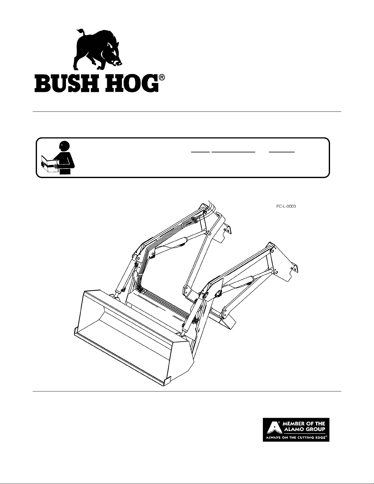
LOADER
Published 01/11 Part No. 50069199
OPERATOR’S MANUAL
BUSH HOG®
2501 Griffin Ave.
Selma, AL 36703
334-874-2700
www.bushhog.com
© 2011 Alamo Group Inc.
$0.00
Page 2

To the Owner/Operator/Dealer
All implements with moving parts are potentially hazardous. There is no substitute for a cautious, safe-minded
operator who recognizes the potential hazards and follows reasonable safety practices. The manufacturer has
designed this implement to be used with all its safety equipment properly attached to minimize the chance of
accidents.
BEFORE YOU START!!Read the safety messages on the implement and shown in your manual. Observe the
rules of safety and common sense!
WARRANTY INFORMATION:
Read and understand the complete Warranty Statement found in this Manual. Fill out the Warranty Registration
Form in full and return it to within 30 Days. Make certain the Serial Number of the Machine is recorded on the
Warranty Card and on the Warranty Form that you retain.
Page 3

TABLE OF CONTENTS
SAFETY SECTION ..............................................................................................................1-1
General Safety Instructions and Practices .........................................................................................................1-2
Operator Safety Instructions and Practices .......................................................................................................1-4
Equipment Operation Safety Instructions and Practices ....................................................................................1-5
Connecting or Disconnecting Implement Safety Instructions and Practices ....................................................1-11
Transporting Safety Instructions and Practices ...............................................................................................1-12
Maintenance and Service Safety Instructions and Practices .... ... .... ... ... ..........................................................1-13
Storage and Parking Safety Instructions and Practices ............................ .... ... ... ... ... .... ... ................................1-15
Concluding Safety Instructions and Practices ..................................................................................................1-15
Decal Location .................................................................................................................................................1-16
Decal Description .............................................................................................................................................1-18
Federal Laws and Regulations ........................................................................................................................1-22
INTRODUCTION SECTION .................................................................................................2-1
ASSEMBLY AND CONNECTING THE LOADER SECTION ..............................................3-1
Assembly Instructions ........................................................................................................................................3-2
Proper Rear Ballasting and Wheel Spacing .......................................................................................................3-3
Installing Mounting Brackets ..............................................................................................................................3-4
Installing Side Frames .......................................................................................................................................3-4
Installing Grease Fittings ...................................................................................................................................3-4
Install Bucket ......................................................................................................................................................3-4
Installing Bucket Level Indicator .. ... ... .... ... .........................................................................................................3-6
Dismounting Loader and Mounting Loader to Tractor .......................................................................................3-6
Dismounting Loader ...........................................................................................................................................3-6
Mounting Loader ................... .............................................................................................................................3-7
OPERATION SECTION .......................................................................................................4-1
Standard Equipment and Specifications ............................................................................................................4-3
Operator Requirements .. ... ... .............................................................................................................................4-4
Tractor Requirements ........................................................................................................................................4-7
ROPS and Seat Belt ..........................................................................................................................................4-7
Tractor Lighting and SMV Emblem ....................................................................................................................4-8
Tractor Ballast ....................................................................................................................................................4-8
Getting On and Off the Tractor ..........................................................................................................................4-9
Boarding the Tractor ..........................................................................................................................................4-9
Dismounting the Tractor ...................................................................................................................................4-10
Starting the Tractor .......................................................................................................................................... 4-11
Pre-Operation Inspection and Service .............................................................................................................4-12
Tractor Pre-Operation Inspection/Service ........................................................................................................4-12
Driving the Tractor and Loader ........................................................................................................................4-19
Operating the Tractor and Loader ................................ ... .... ... ..........................................................................4-19
Operating the Loader .......................................................................................................................................4-24
Operating Bale Spear ......................................................................................................................................4-37
Shutting Down the Implement ..........................................................................................................................4-38
Loader Storage ................................................................................................................................................4-38
Transporting the Tractor and Implement ..........................................................................................................4-39
Hauling the Tractor and Implement ..................................................................................................................4-42
Troubleshooting Guide ..................................................................................................................................... 4-43
Page 4

MAINTENANCE SECTION ..................................................................................................5-1
Lubrication Schedule .........................................................................................................................................5-4
Daily Maintenance .............................................................................................................................................5-5
Hydraulic Pressure Check .................................................................................................................................5-6
Cylinder Service ................................................................................................................................................. 5-6
Lift and Bucket Cylinder Dissemble ............................. ... .... ... ... .........................................................................5-7
Lift and Bucket Cylinder Reassembly ............................. .... ... ............................................................................5-7
Prince LVR Valve Service .. ... .... .........................................................................................................................5-8
Valve Disassembly .............................................................................................................................................5-9
Valve Reassembly ...........................................................................................................................................5-10
Relief Valve, Load Check Plugs and Power Beyond Sleeve ...........................................................................5-10
Replacing Handle Parts ................................................................................................................................... 5-10
Storage ............................................................................................................................................................5-10
Proper Torque for Fasteners ............................................................................................................................5-12
Page 5

SAFETY SECTION
Safety Section 1-1
Page 6
SAFETY
A careful operator is the best operator. Safety is of primary importance to the manufacturer and should be to
the owner/operator . Most accidents can be avoided by being aware of your equipment, your surroundings, and
observing certain precautions. The first section of this manual includes a list of Safety Messages that, if
followed, will help protect the operator and bystanders from injury or death. Read and understand these Safety
Messages before assembling, operating or servicing this Implement. This equipment should only be operated
by those persons who have read the manual, who are responsible and trained, and who know how to do so
responsibly.
The Safety Alert Symbol combined with a Signal Word, as seen below, is used throughout this
manual and on decals which are attached to the equipment. The Safety Alert Symbol means:
“ATTENTION! BECOME ALERT! YOUR SAFETY IS INVOLVED!” The Symbol and Signal Word
are intended to warn the owner/operator of impending hazards and the degree of possible injury
faced when operating this equipment.
Indicates an imminently hazardous situation that, if not avoided, WILL result in DEATH OR
VERY SERIOUS INJURY.
Indicates an imminently hazardous situation that, if not avoided, COULD result in DEATH
OR SERIOUS INJURY.
Indicates an imminently hazardous situation that, if not avoided, MAY result in MINOR
INJURY.
Identifies special instructions or procedures that, if not strictly observed, could result in
damage to, or destruction of the machine, attachments or the environment.
NOTE: Identifies points of particular interest for more efficient and convenient operation or repair.
(SG-1)
Practice all usual and customary safe working precautions and above all---remember safety is
up to YOU
. Only YOU can prevent serious injury or death from unsafe practices.
Si no lee ingles, pida ayuda a alguien que si lo lea para que le traduzca las
medidas de seguridad.
(SG-3)
Operate this Equipment only with a Tractor equipped with an approved rollover-protective system (ROPS). Always wear seat belts. Serious injury or
even death could result from falling off the tractor--particularly during a turnover
when the operator could be pinned under the ROPS.
(SG-7)
General Safety Instructions and Practices
SAFETY
1947/2047 01/11 Safety Section 1-2
© 2011 Alamo Group Inc.
Page 7
SAFETY
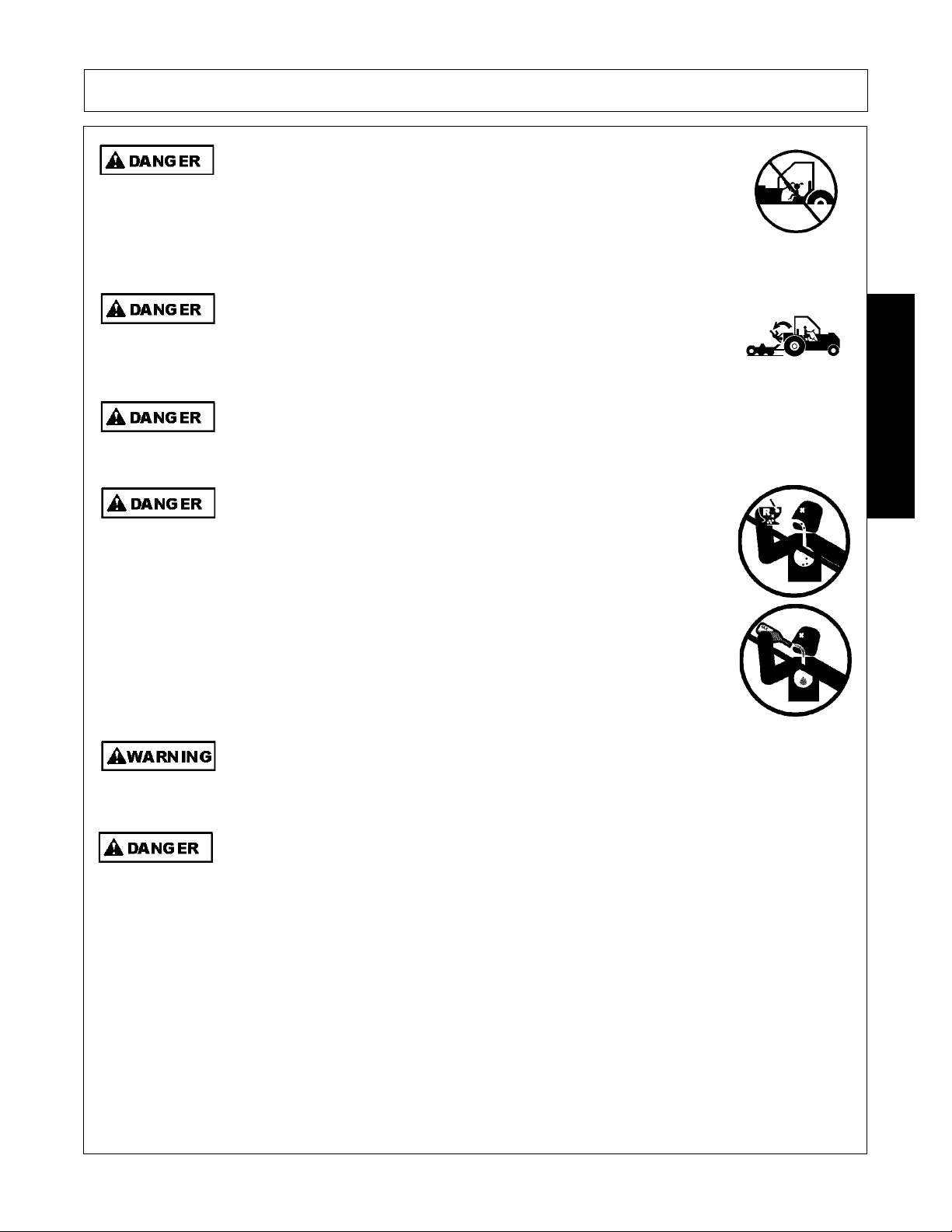
Never allow children to operate, ride on, or come close to the Tractor or
Implement. Usually, 16-17 year-old children who are mature and
responsible can operate the implement with adult supervision, if they
have read and understand the Operator’s Manuals, been trained in
proper operation of the tractor and Implement, and are physically large
enough to reach and operate the controls easily.
(SG-11)
Never allow children or other persons to ride on the Tracto r or Implement.
Falling off can result in serious injury or death.
(SG-10)
Never allow children to play on or around Tractor or Implement. Children can slip or fall off
the Equipment and be injured or killed. Inadvertent contact with controls can cause the
Implement to shift or fall crushing themselves or others.
(SG-25)
DO NOT use drugs or alcohol immediately before or while operating the
Tractor and Implement. Drugs and alcohol will affect an operator’s
alertness and coordination and therefore affect the operator’s ability to
operate the equipment safely. Before operating the Tractor or Implement,
an operator on prescription or over-the-counter medication must consult
a medical professional regard ing any side effects of the medication that
would hinder their ability to operate the Equipment safely. NEVER
knowingly allow anyone to operate this equipment when their alertne ss or
coordination is impaired. Serious injury or death to the operator or others
could result if the operator is under the influen ce of drugs or a lcohol.
(SG-27)
Engine Exhaust, some of its constituents, and certain vehicle components contain or emit
chemicals known to the state of California to cause cancer and birth defects or other
reproductive harm.
(SG-30)
Never walk or work under any raised boom or bucket. The Boom could fall and cause
serious bodily injury or death. Always lower the boom and bucket flat on the ground or
support the Boom and bucket on safety stands. Unload all hydraulic actuators prior to
performing any maintenance. To do this, set the bucket on the ground then kill the tractor
engine. Push and pull the control levers in and out several times to remove pressure. Do
not work under raised Boom or Bucket unless components are securely blocked up to
prevent inadvertent dropping.
(SBH-7)
SAFETY
1947/2047 01/11 Safety Section 1-3
© 2011 Alamo Group Inc.
Page 8

SAFETY
Never operate the Tractor or Implement until you have read and
completely understand this Manual, the Tractor Operator’s Manual, and
each of the Safety Messages found in the Manual or on the Tractor and
Implement. Learn how to stop the tractor engine suddenly in an
emergency. Never allow inexperienced or untrained personnel to
operate the Tractor or Implement without supervision. Make sure the
operator has fully read and understood the manuals prior to operation.
(SG-4)
The operator and all support personnel should wear hard hats, safety
shoes, safety glasses, and proper hearing protection at all times for
protection from injury including injury from items that may be thrown by
the equipment.
(SG-16)
PROLONGED EXPOSURE TO LOUD NOISE MAY CAUSE
PERMANENT HEARING LOSS! Tractors with or without an Implement
attached can often be noisy enough to cause permanent hearing loss.
We recommend that you always wear hearing protection if the noise in
the Operator’s position exceeds 80db. Noise over 85db over an
extended period of time will cause severe hearing loss. Noise over 90db
adjacent to the Operator over an extended period of time will cause
permanent or total hearing loss. NOTE: Hearing loss from loud noise
[from tractors, chain saws, radios, and other such sources close to the
ear] is cumulative over a lifetime without hope of natural recovery.
(SG-I7)
Always read carefully and comply fully with the manufacturer’s
instructions when handling oil, solvents, cleansers, and any other
chemical agent.
(SG-22)
Never run the Tractor engine in a closed building or without adequate ventilation. The
exhaust fumes can be hazardous to your health.
(SG-23)
Battery posts, terminals and related accessories contain lead and lead compounds,
chemicals known to the state of California to cause cancer, birth defects or other
reproductive harm.
(SG-31)
Operator Safety Instructions and Practices
SAFETY
1947/2047 01/11 Safety Section 1-4
© 2011 Alamo Group Inc.
Page 9
SAFETY
Prolonged operation may cause operator boredom and fatigue affecting safe operation.
Take scheduled work breaks to help prevent these potentially impaired operating
conditions. Never operate the Implement and Tractor in a fatigued or bored mental state
which impairs proper and safe operation.
(SG-32)
Use extreme caution when getting onto the Implement to perform repairs, maintenan ce and
when removing accumulated material. Only stand on solid flat surfaces to ensure good
footing. Use a ladder or raised stand to access high spots which cannot be reached from
ground level. Slipping and falling can cause serious injury or death.
(SG-33)
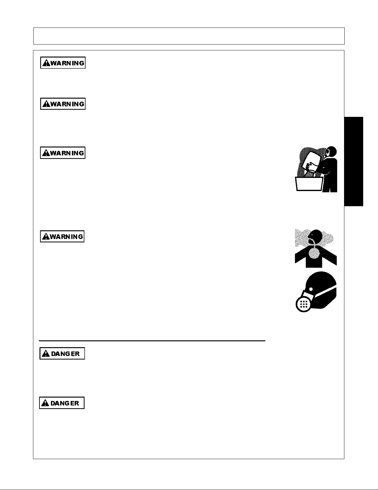
Use extreme care when loading, carrying or handling any agricultural
fertilizers, chemicals or biological residue. Follow the manufacturer’s
handling instructions and wear appropriate Personal Protective
Equipment including gloves, safety glasses and respirator when required.
If you are using a tractor equipped with a cab, make sure the cab is rated
for appropriate environmental exposure. Be safe and always wear proper
protection. Short or long term exposure to certain chemicals and
materials can result in serious injury or death.
(SL-19)
Repeated or substantial breathing of hazardous dusts, including
crystalline silica, could cause fatal or serious respiratory disease including
silicosis. Concrete, masonry, many types of rock, and various other
materials contain silica sand. California lists respirable crystalline silica as
a substance known to cause cancer. Operation of this equipment under
certain conditions may generate airborne dust particles that could contain
crystalline silica. In those conditions, personal protective equipment
including an appropriate respirator must be used. If excessive dust is
generated, a dust collection or suppression system should also be used
during operation.
(SG-41)
This Implement may be wider than the Tractor. Be careful when operating or transporting
this equipment to prevent the Implement from running into or striking sign posts, guard rails,
concrete abutments or other solid objects. Such an impact could cause the Implement and
Tractor to pivot violently resulting in loss of steering control, serious injury, or even death.
Never allow the Implement to contact obstacles.
(S3PT-12)
Never grasp control levers when mounting the machine. (SBH-4)
SAFETY
Equipment Operation Safety Instructions and Practices
1947/2047 01/11 Safety Section 1-5
© 2011 Alamo Group Inc.
Page 10
SAFETY
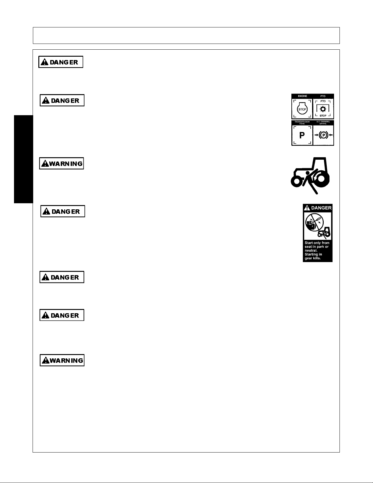
The Boom is designed only to position and operate the Bucket which is att ached to it. Never
attempt to lift, pull, or push other solid objects with the boom or bucket. Serious injury could
result from a structural failure when the Boom is used for purposes other than those for
which it was designed.
(SBH-9)
BEFORE leaving the tractor seat lower the implement, set the parking
brake and/or set the tractor transmission in parking gear, disengage the
PTO, stop the engine, remove the key, and wait for all moving parts to
stop. Place the tractor shift lever into a low range or parking gear to
prevent the tractor from rolling. Never dismount a Tractor that is moving
or while the engine is running. Operate the Tractor controls from the
tractor seat only.
(SG-9)
Do not mount or dismount the Tractor while the t ractor is moving . Mount
the Tractor only when the Tractor and all moving parts are
completelystopped.
(SG-12)
Start tractor only when properly seated in the Tractor seat. Starting a
tractor in gear can result in injury or death. Read the Tractor operators
manual for proper starting instructions.
(SG-13)
Operate the Tractor and/or Implement control s only while properly seated in the Tractor seat
with the seat belt securely fastened around you. Inadvertent movement of the Tractor or
Implement may cause serious injury or death.
(SG-29)
DO NOT operate this Implement on a Tractor that is not properly maintained. Should a
mechanical or Tractor control failure occur while operating, immediately shut down the
Tractor and perform repairs before resuming operation. Serious injury and possible death
could occur from not maintaining this Implement and Tractor in good operating condition.
(SG-36)
Do Not operate this equipment in areas where insects such as bees may attack you and/or
cause you to lose control of th e equipment. If you must enter in such areas, use a tractor
with an enclosed Cab and close the windows to prevent insects from entering. If a tractor
cab is not available, wear suitable clothing including head, face, and hand protection to
shield you from the insects. Attacking insects can cause you to lose control of the tractor,
which can result in serious injury or death to you o r bystanders. Never dismount a moving
tractor.
(SG-40)
SAFETY
1947/2047 01/11 Safety Section 1-6
© 2011 Alamo Group Inc.
Page 11
SAFETY
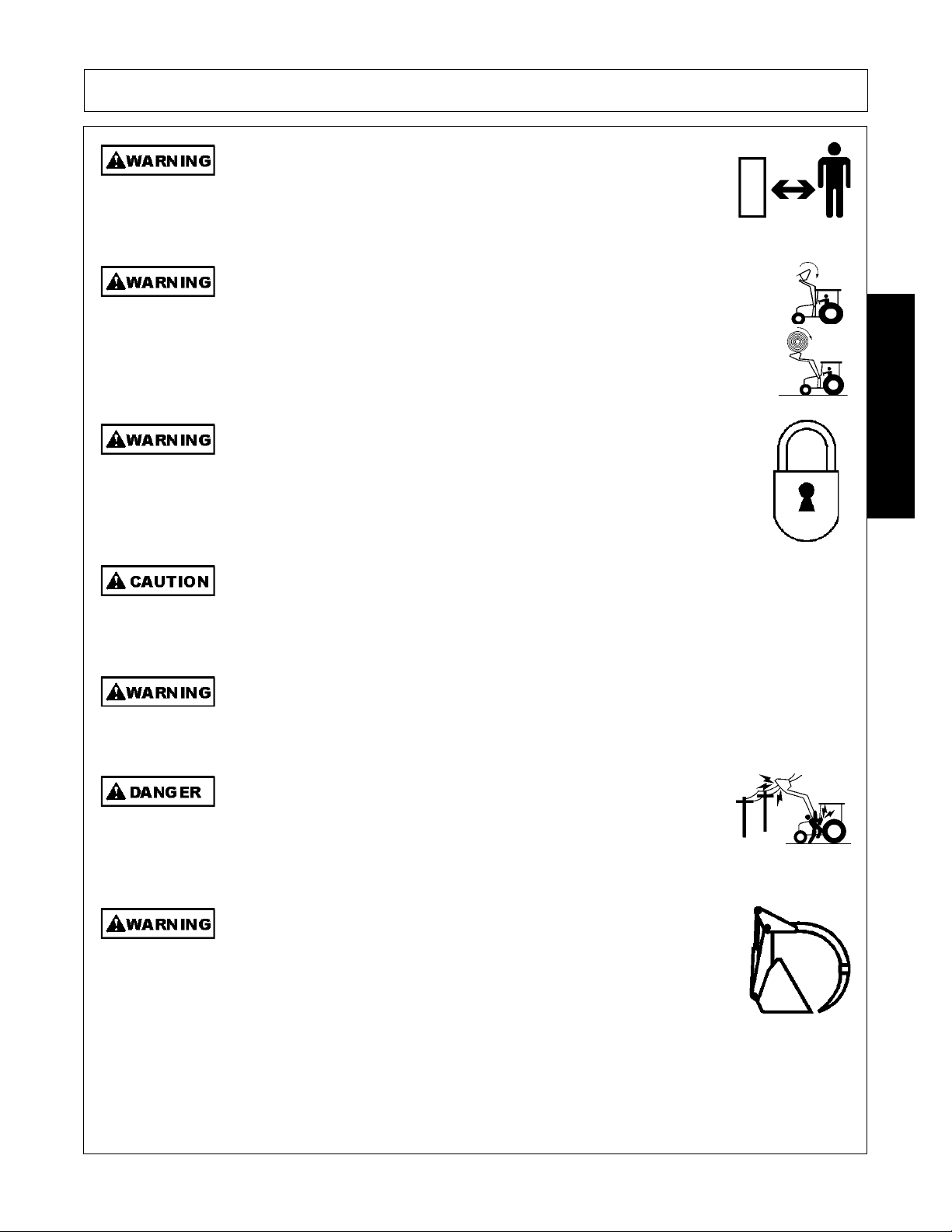
Keep bystanders 10 feet away from the tractor and loader while
operating. The bystanders could enter the path of the tractor or items
could fall from the loader resulting in serious injury to the bystander.
(SL-01)
For added safety when lifting loads above the height of the operator,
install a certified Falling Object Protective Structure. Shiftable loads,
round bales, large loose items, and loader attachments can fall toward
the operator resulting in serious injury or death. Falling Object Protective
Structure (FOPS) rated Cab may be obtained from the tractor dealer or
other sources.
(SL-02)
Before dismounting the tractor and loader lower the loader to the ground or
onto solid support blocks. Engage the loader valve travel lock to prevent
inadvertent movement of the valve controls causing the loader to suddenly
move and drop. Sudden dropping of the loader and attachment could
result in serious injury.
(SL-05)
Use extra care when turning or stopping. Allow for increased length and weight of added
loader . The lo ade r ad ds five to six fee t of le ngt h in front of the tractor and si gnificant weigh t.
Allow extra distance when stopping or turning. Do not allow loader or attachment to conta ct
solid objects.
(SL-07)
Do not raise the loader into an overhead structure or allow a raised attachment to contact
overhead structures. Sudden or unexpected contact with an overhead structure could result
in serious injury.
(SL-08)
Do not let the loader or attachment contact electrical power lines. Contact
with electrical power lines can result in serious injury or electrocution. If
the loader attachment contacts a power line remain in the tractor seat
until the power has been shut off. Stepping off the tractor can permit
electrical current to pass through the body resulting in electrocution.
(SL-09)
Store the grapple bucket or bale spear attachment with the point(s) on the
ground. Walking into the point of the bale or grapple spear can cause
serious bodily injury. Never drive the bale spear or grapple bucket
attachment forward if a bystander is in front of the loader.
(SL-10)
SAFETY
1947/2047 01/11 Safety Section 1-7
© 2011 Alamo Group Inc.
Page 12
SAFETY
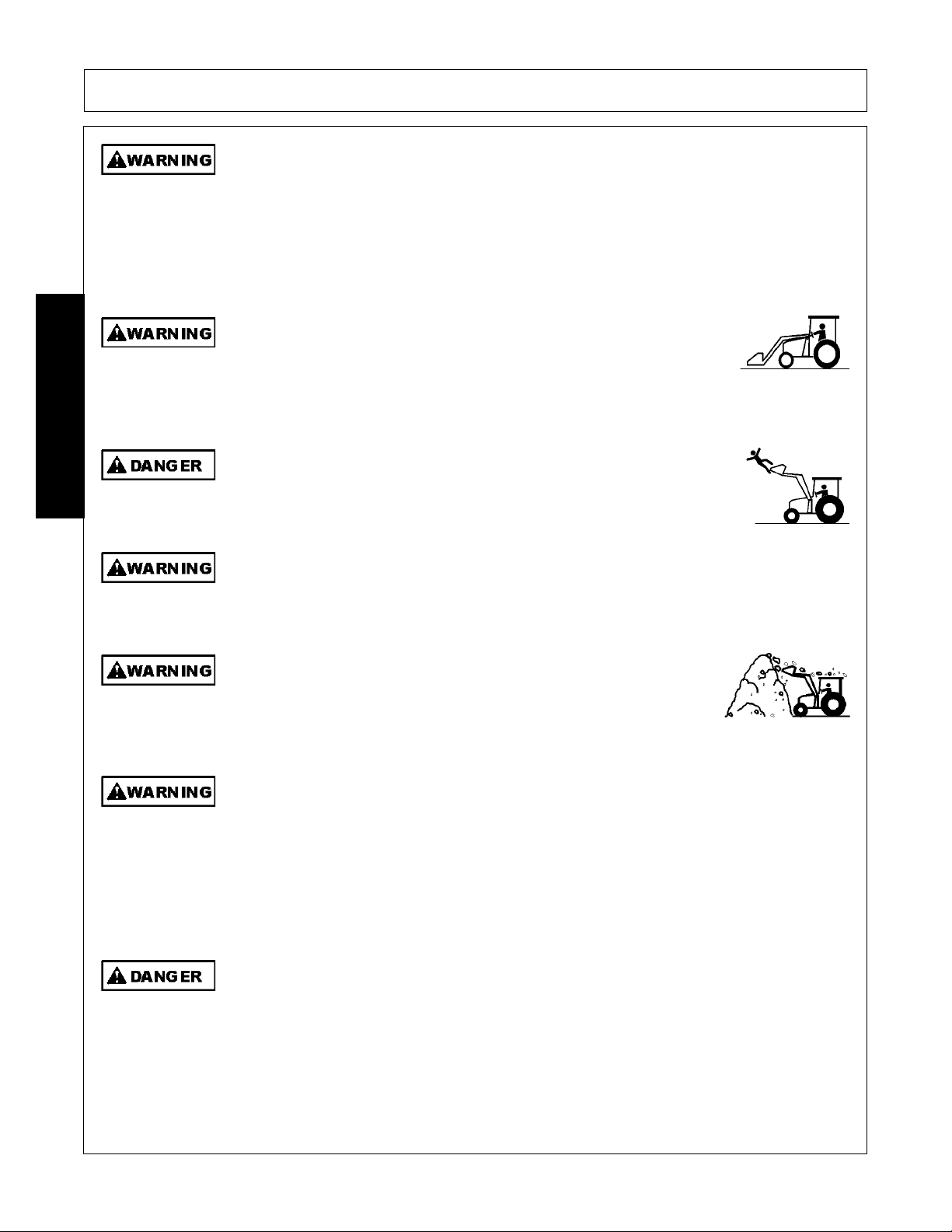
Only mount the loader on a tractor that is listed on the mounting instructions. Never mount
on a tricycle steering front axle. Move the tractor front and rear wheels to the widest spacing
and add the recommended rear tractor ballast to prevent tractor tip over. Keep the tractor
tires properly inflated. Maintain at least 25% of the total Tractor and Loader weight including
the maximum load in the bucket or attachment on the rear axle. Always wear your seatbelt
and make sure the ROPS structure is fully deployed to prevent serious injury or death from
the tractor tipping over.
(SL-11)
Carry the loader and attachment low when transporting to reduce the
potential of the tractor tipping over. Transport on slopes only at slow
speeds and use gradual turning angles. Tractor wheel contact with any
wash out, drop off or ground obstruction with a raised loader could result
in the tractor tipping over and causing serious injury.
(SL-12)
Do not work from the loader or at tachments. Do now allow any riders on
the loader, tractor or attachments. Falling off the loader could result in
serious injury and/or tractor run over.
(SL-14)
Do not operate the loader from the ground. Operate the tr actor and loader only while seated
in the tractor seat with the seatbelt fastened. The loader could fall crushing a person
resulting in serious injury or death.
(SL-16)
Use extreme care when piling material above 6 feet high. Material
could shift and fall onto the operator or by standers. The material could
crush or suffocate the operator or bystander resulting in serious injury
or death.
(SL-17)
Know before you DIG. Call 888-258-0808 and request that all buried utilities locations be
identified before digging in unfamiliar ground. Do not let the loader or attachment contact
buried electrical power lines, utilities or gas lines. Contact with electrical power lines can
result in serious bodily injury or electrocution. If the loader contacts a power line, remain in
the tractor seat until the power has been shut off. Stepping off the tractor can permit
electrical current to pass through the body resulting in electrocution.
(SL-18)
Do not use loader as a jack to raise the tractor tires off the ground. The loader could fail
causing the tractor and loader to fall to the ground resulting in serious injury.
(SL-25)
SAFETY
1947/2047 01/11 Safety Section 1-8
© 2011 Alamo Group Inc.
Page 13
SAFETY
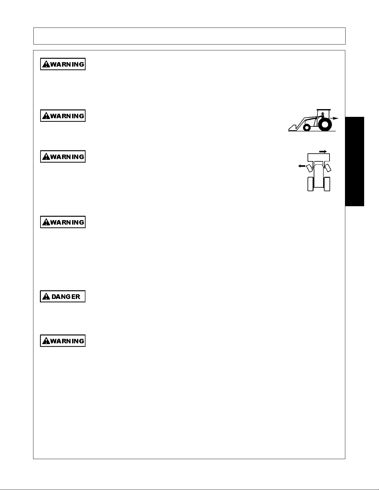
Use extreme care when loading, transporting or dumping loads that impair or partially block
the operator’s line of sight. Know where you are traveling. Make sure no bystanders are in
the area of travel. If a bystander assists in pr oviding guidance, make sure they are not in the
path of travel. Keep all bystanders 25 feet away from travel path.
(SL-29)
Always look behind you before backing up. Make sure you are looking
in the direction of travel. A bystander could walk behind the tractor.
Running into a bystander can result in serious inju ry or death.
(SL-30)
Some tractors are equipped with a “Super Steer” front axle. When a
loader is mounted to this type of tractor, the bucket will shift in the
opposite direction from which the wheels are turned. Maximum shift will
be approximately 8 inches and most noticeable when the tractor is
stationary. Sudden or unexpected movement of the loader and
attachment could result in serious injury to the operator or bystanders.
(SL-33)
Operate the tractor and loader only in conditions where you have clear visibility in daylight
or with adequate artificial lighting. Never operate in darkness or fo gg y condition s wher e you
cannot clearly see at least 100 feet in front and to the sides of the tractor. Make sure you
can clearly see bystanders, ditche s, steep slopes, drop-offs, overhead obstructions, power
lines, and debris or obstruction in the tr avel path. If you are unable to clearly see these
types of items discontinue operating. Contact with unseen vehicles, bystanders,
obstructions, or drop-offs can cause serious injury.
(SL-35)
Be particularly careful in transport. The Implement has raised and moved the center of
gravity to the front of the Power Unit increasing the possibility of overturn and tipping
forward. Turn curves or go up slopes only at low speed and using a gradual turning angle.
Go up slopes with the Implement located uphill. Slow down on rough or uneven surfaces.
(SPU-2)
Never leave the Implement and Power Unit unattended while the Implement is in the raised
position. Accidental operation of a lifting lever or a hydraulic failure may cause the
implement to suddenly fall causing serious injury or possible death to anyone who might
inadvertently be under the Implement. Lower the implement carefully to the gr ound. Do not
put hands or feet under lifted componen ts.
(SPU-3)
SAFETY
1947/2047 01/11 Safety Section 1-9
© 2011 Alamo Group Inc.
Page 14
SAFETY
The center of gravity of a Power Unit equipped with a front-mounted Implement is shifted to
the front and removes weight from the rear wheels. The Power Unit should maintain at
least 25% total weight with the maximum load in the bucket or attachment on the rear
wheels to prevent tipping forward, loss of steering control, and possible injury. Add
counterweight if required when operating on slopes and proceed with the load uphill to
prevent tipping. Reference the Power Unit’s Operator’s Manual or an authorized dealer for
information on adding additional weight.
(SL-37)
Your driving vision may be reduced or impaired by the tractor, cab, or implement. Before
driving on public roadways identify any limited vision areas, and make adjustments to your
operating position, mirrors, and the implement transport position so that you can clearly
see the area where you will be traveling, and any traffic that may approach you. Failure to
maintain adequate vision of the public roadway and traffic can result in serious injury or
even death.
(STI-10)
Make sure the hydraulic quick disconnects are fully seated into the connections. Do not use
the loader if the hydraulic connection is leaking. Leaking oil could allow the loader to fall
resulting in a serious crushing injury.
(SL-22)
If the loader valve controls fail to functions properly discontinue use of the tractor and
loader until the controls are properly repaired. Sudden or unexpected movement or
dropping of the loader and attachment could result in seriou s injury.
(SL-31)
Make sure all air is purged from the hydraulic system before using the loader. Air in the
system can cause the loader to respond sluggishly or with unexpected movement. The air
can be purged from the cylinder lines by fully cycling the cylinders several times from the
fully closed to fully open position. Sudden or unexpected movement or dropping of the
loader and attachment could result in serious injury.
(SL-32)
SAFETY
1947/2047 01/11 Safety Section 1-10
© 2011 Alamo Group Inc.
Page 15
SAFETY
Do not stand or allow bystander or coworkers between the loa de r and th e
tractor while installing or disconnecting the loader from the tractor. Keep
hands and body clear of the loader and the loader mounts. Serious injury
or death can result from a person being crushed between the tractor and
loader.
(SL-03)
Never allow anyone to get under the loader or attachment or to reach
through the loader lift arms when raised. Serious injury could result from
crushing or pinching by the loader or attachment.
(SL-06)
Make sure the loader is properly attached to the tractor and the retaining pins securely lock
the loader into position. Improper mounting of the loader onto the tractor can result in the
loader falling causing serious injury.
(SL-23)
Make sure all tractor and loader guards are in place and properly functioning. Do not use an
attachment if the roll back guards are damaged or missing. The roll back guards prevents
items carried in the attachment from rolling back onto the operator causing serious injury.
For added safety when lifting loads above the height of the operator, install a certified
Falling Object Protective Structure.
(SL-28)
Connecting or Disconnecting Implement Safety Instructions and
Practices
SAFETY
1947/2047 01/11 Safety Section 1-11
© 2011 Alamo Group Inc.
Page 16
SAFETY
Transport only at speeds where you can maintain control of the
equipment. Serious accidents and injuries can result from operating this
equipment at high speeds. Understand the Tractor and Implement and
how it handles before transporting on streets and highways. Make sure the Tractor steering
and brakes are in good condition and operate properly.
Before transporting the Tractor and Implement, determine the proper transport speeds for
you and the equipment. Make sure you abide by the following rules:
Test the tractor at a slow speed and increase the speed slowly. Apply the Brakes smoothly
to determine the stopping characteristics of the Tractor and Implement. As you increase
the speed of the Tractor the stopping distance increases. Determine the maximum
transport speed not to exceed 20 mph (30 kph) for transporting this equipment.
Test the equipment at a slow speed in turns. Increase the speed through the turn only after
you determine that the equipment can be operated at a higher speed. Use extreme care
and reduce your speed when turning sharply to prevent the tractor and implement from
turning over. Determine the maximum turning speed for you and this equipment before
operating on roads or uneven ground.
Only transport the Tractor and Implement at the speeds which allow you to properly control
the equipment.
Be aware of the operating conditions. Do not operate the Tractor with weak or faulty brakes
or worn tires. When operating down a hill or on wet or rain slick roads, the braking distance
increases: use extreme care and reduce you r speed. When operating in traffic always use
the Tractor’s flashing warning lights and red uce your speed. Be a ware of traf fic around yo u
and watch out for the other guy.
(SG-19)
Before transporting the tractor and Loader engage the loader valve travel
lock to prevent inadvertent contact with the joystick controller causing
sudden dropping of the loader and attachment. If the loader attachment,
such as a bucket, were to drop suddenly and hit the ground while
transporting, the tractor could stop immediately resulting in the operator
hitting the steering wheel or flying our of the operator’s seat. Serious injury
could result.
(SL-04)
Do not raise the loader on a hillside. Do not transport across a slope with
a raised loader. When the loader is raised, the center of gravity of the
tractor and loader is raised increasing the potential for the tractor to tip
over. Tractor wheel contact with any wash out, drop off or the ground
obstruction with a raised loader could result in the tractor tipping over and
causing serious bodily injury.
(SL-21)
Transporting Safety Instructions and Practices
SAFETY
1947/2047 01/11 Safety Section 1-12
© 2011 Alamo Group Inc.
Page 17
SAFETY
Lower the loader to the bed of the truck or trailer when transporting the
tractor and loader with a truck. Measure to ensure the transport height
does not exceed the legal limits. Contact with overhead obstructions or
power lines can cause property damage or serious injury.
(SL-34)
In case of mechanical difficulty during operation, place the transmission in the park
position, set the parking brake, shut down all power, including the PTO and the engine and
remove the key. Wait until all rotating motion has stopped before dismounting.
(SG-39)
Transport an empty bale spear tilted back in the vertical position to
prevent unintended harm to a person, animal or object. Serious injury
or death may occur from a bale spear puncture.
(SL-39)
Never drive the power unit with the bucket or plow in the raised position.
Traveling with the bucket or plow in the raised position increases the
chances of colliding with overhead obstructions and making the unit more
prone to tipping over.
(SNPO-37)
Never interfere with factory-set hydraulic calibrations. Any change in calibration could
cause a failure of the equipment and may result in injury.
(SBH-13)
READ, UNDERSTAND, and FOLLOW the following Safety Messages. Serious injury or
death may occur unless care is taken to follow the warnings and instructions stated in the
Safety Messages. Always use good common sense to avoid hazards.
(SG-2)
Always maintain the safety signs in good readable condition. If th e safety signs are missing,
damaged, or unreadable, obtain and install replacement safety signs immediately.
(SG-5)
Make certain that the “Slow Moving Vehicle” (SMV) sign is installed in
such a way as to be cl early visible and legible. When transport ing the
Equipment use the Tractor flashing warning lights and follow all local
traffic regulations.
(SG-6)
Do not modify or alter this Implement. Do not permit anyone to modify or alter this
Implement, any of its components or any Implement function.
(SG-8)
SAFETY
Maintenance and Service Safety Instructions and Practices
1947/2047 01/11 Safety Section 1-13
© 2011 Alamo Group Inc.
Page 18
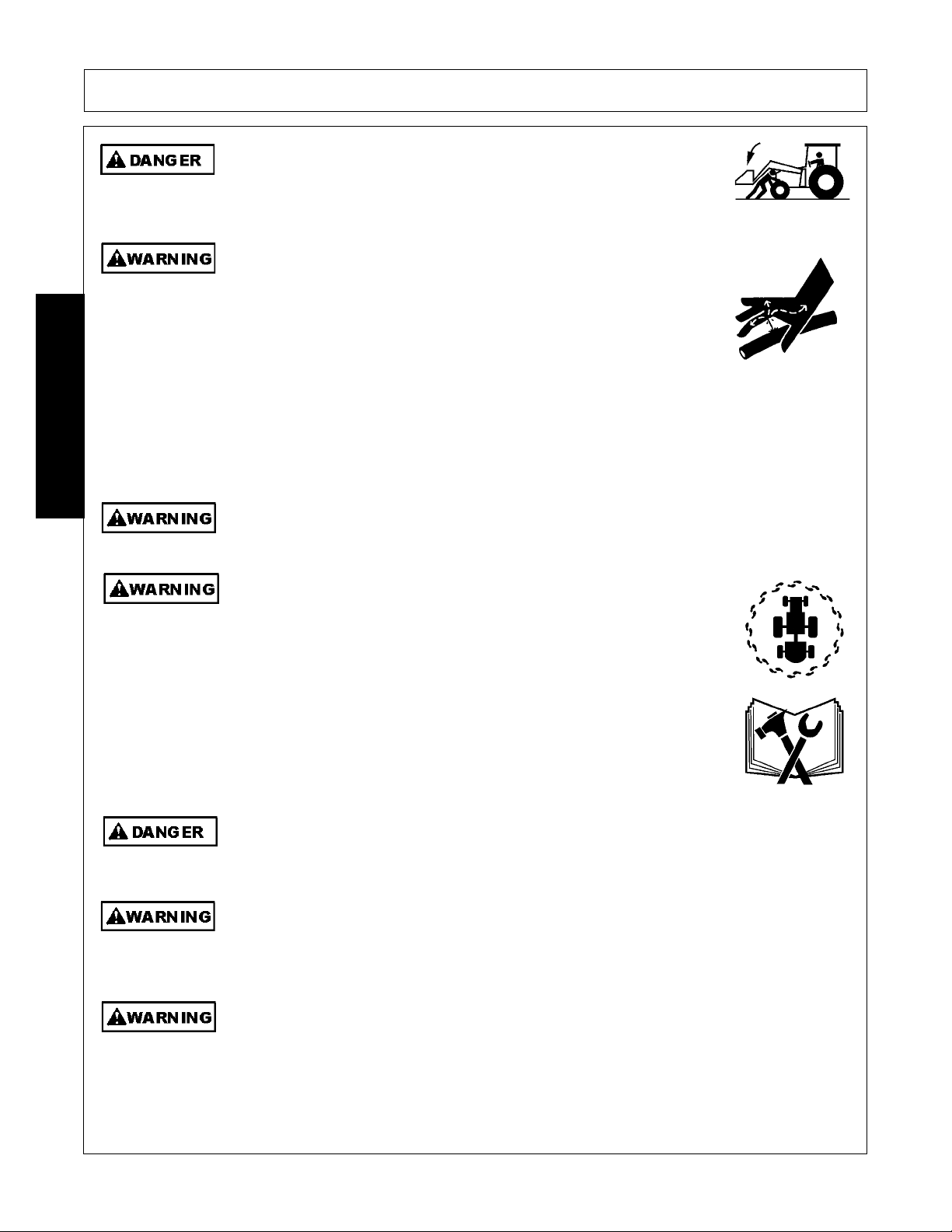
SAFETY
Never work under the Implement, the framework, or any lifted component
unless the Implement is securely supported or blocked up to prevent
sudden or inadvertent falling which could cause serious injury or even
death.
(SL-36)
Do not operate this Equipment with hydraulic oil or fuel leaking. Oil
and fuel are explosive and their presence could present a hazard. Do
not check for leaks with your hand! High-pressure oil streams from
breaks in the line could penetrate the skin and cause tissue damage
including gangrene. To check for a hose leak, SHUT the unit ENGINE
OFF and remove all hydraulic pressure. Wear oil imp ene trab le glo ves ,
safety glasses and use Cardboard to check for evidence of oil leaks. If
you suspect a leak, REMOVE the HOSE and have it tested at a Dealer.
If oil does penetrate the skin, have the injury treated immediately by a
physician knowledgeable and skilled in this procedure.
(SG-15)
Never attempt to lubricate, adjust, or remove material from the Implement while it is in
motion or while tractor engine is running.
(SG-20)
Periodically inspect all moving parts for wear and replace when
necessary with authorized service parts. Look for loose fasteners, worn
or broken parts, and leaky or loose fittings. Make sure all pins have
cotter pins and washers. Serious injury may occur from not maintaining
this machine in good working order.
(SG-21)
Do Not fill fuel tank while engine is running. Refuel only after engine has cooled down. If
fuel is spilled, move machine away from the area of the spill and avoid creating any source
of ignition until the fuel has evaporated.
(SBH-49)
Avoid contact with hot surfaces including hydraulic oil tanks, pumps, motors, valves and
hose connections. Relieve hydraulic pressure before performing maintenance or repairs.
Use gloves and eye protection when servicing hot components. Contact with a hot surface
or fluid can cause serious injury from burns or scalding.
(SG-34)
Use caution and wear protective gloves when handling sharp objects such as blades,
knives, and other cutting edges. Be alert to worn component surfaces which have sharp
edges. Sharp surfaces can inflict severe laceration injuries if proper hand protection is not
worn.
(SG-37)
SAFETY
1947/2047 01/11 Safety Section 1-14
© 2011 Alamo Group Inc.
Page 19
SAFETY
Avoid contact with hot surfaces of the engine or muffler. Use gloves and eye protection
when servicing hot components. Contact with a hot surface or fluid can cause serious injury
from burns or scalding.
(SG-38)
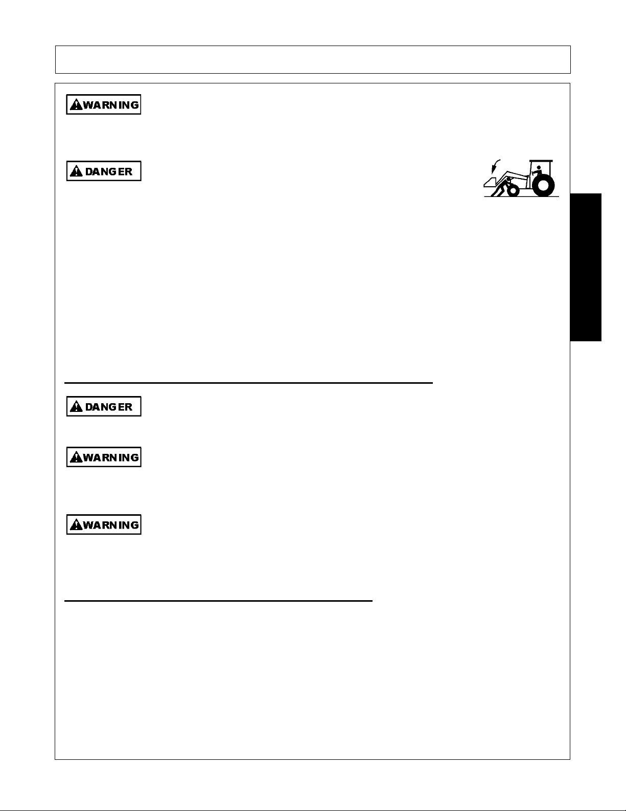
Never allow anyone to get under the loader or attachment or to reach
through the loader lift arms when raised. Serious injury could result from
crushing or pinching by the loader or attachment.
(SL-06)
PARTS INFORMATION
Bush Hog products are designed utilizing specifically matched system components to ensure optimum
equipment performance. These parts are made and tested to Bush Hog specifications. Non-genuine "will fit"
parts do not consistently meet these specifications. The use of “will fit” parts may reduce equipment
performance, void warranties, and present a safety hazard. Use genuine Bush Hog parts for economy and
safety.
(SPBH-2)
SEE YOUR BUSH HOG DEALER
Never crawl under or allow children to play around or on a loader that is disconnected from
the tractor. The loader could fall crushing a person resulting in serious injury or death.
(SL-13)
Do not remove the attachment from the loader when the loader is disconnected from the
tractor. The attachment stabilizes the loader. If the attachment is removed, the loader will
fall and could result in serious injury.
(SL-26)
Only disconnect and store the loader on firm flat ground. Make sure the loader stands are
properly installed and rest on firm ground or support blocks. If the stands sink or fail, the
loader could fall causing serious injury.
(SL-27)
In addition to the design and configuration of this Implement, including Safety Signs and Safety Equipment,
hazard control and accident prevention are dependent upon the awareness, concern, prudence, and proper
training of personnel involved in the operation, transport, maintenance, and storage of the machine. Refer
also to Safety Messages and operation instruction in each of the appropriate sections of the Tractor and
Equipment Manuals. Pay close attention to the Safety Signs affixed to the Tractor and Equipment.
(SG-18)
SAFETY
Storage and Parking Safety Instructions and Practices
Concluding Safety Instructions and Practices
1947/2047 01/11 Safety Section 1-15
© 2011 Alamo Group Inc.
Page 20
SAFETY
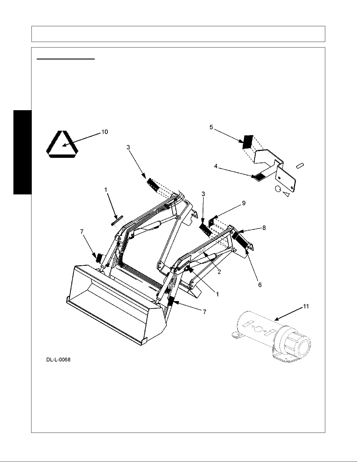
Decal Location
NOTE: Bush Hog supplies safety decals on this product to promote safe opera tion. Da mag e to the decals may
occur while in shipping, use, or reconditioning. Bush Hog cares about the safety of its customers, operators,
and bystanders, and will replace the safety decals on this product in the field, free of charge (Some shipping
and handling charges may apply). Contact your Bush Hogdealer to order replacement decals.
SAFETY
1947/2047 01/11 Safety Section 1-16
© 2011 Alamo Group Inc.
Page 21

SAFETY
ITEM PART NO. QTY LEVEL DESCRIPTION
1. 50057411 2 LOGO Bush Hog 3.20” x 14.5”
2. 50069067 2 MODEL 1947
50069068 2 MODEL 2047
3. 52740 2 WARNING Oil Leaks
4. 52203 1 WARNING Lock Valve in Transport
5. 52204 1 INSTRUCT Loader Positions
6. D469 1 WARNING Loader Safety
7. D468 2 DANGER Crushing, Electrocution, Falling Hazard
8. D471 1 WARNING Handling Bales
9. D470 1 DANGER Use ROPS, Seatbelt, Rear Ballast
10. 03200347 * REFLCTR SMV Sign
11. 00776031 1 _________ Canister, Operator’s Manual
* - Provided by Tractor Manufacturer. Replace if missing.
NOTE: Order D438 Safety Decal Sheet which includes all safety decals.
SAFETY
1947/2047 01/11 Safety Section 1-17
© 2011 Alamo Group Inc.
Page 22
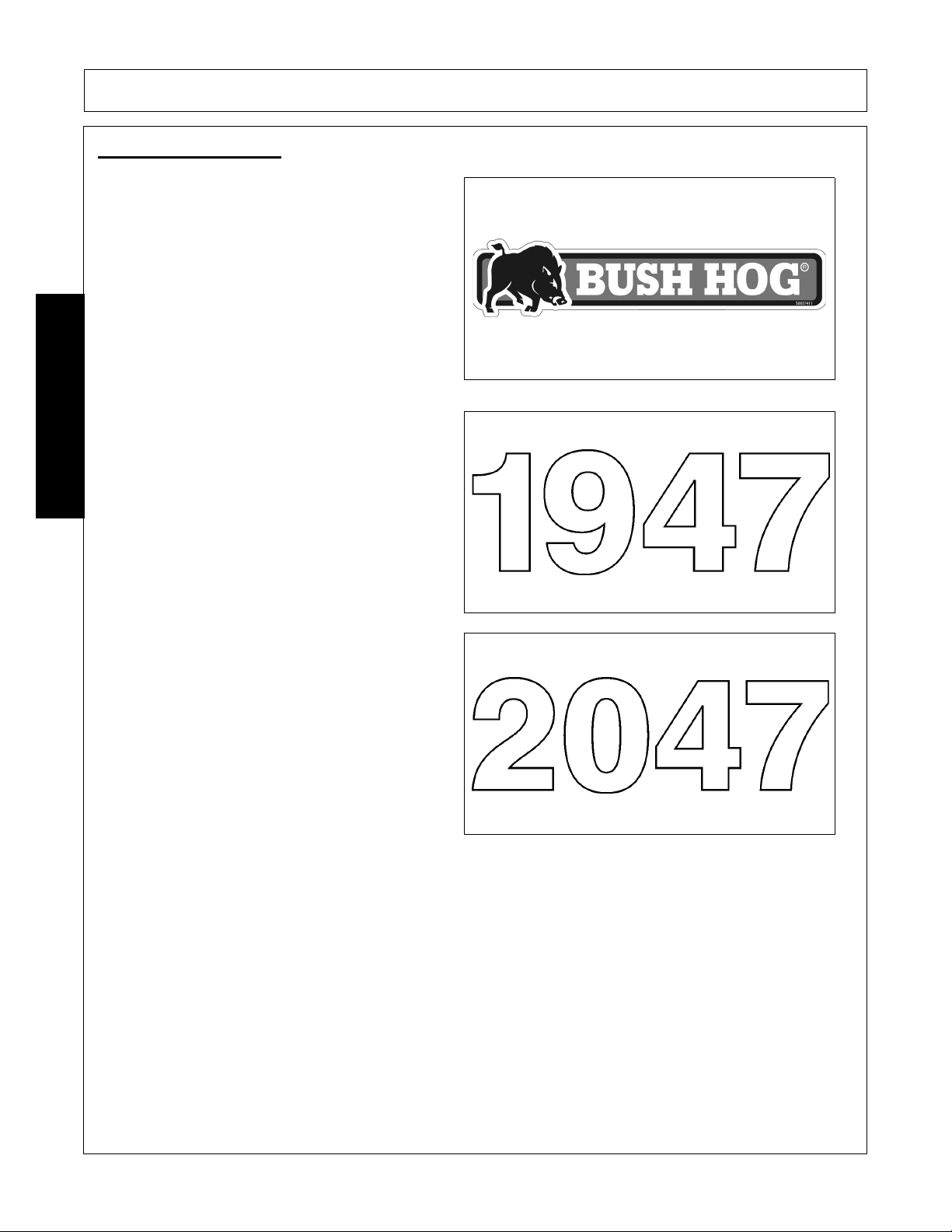
Decal Description
P/N 50057411
Logo: BUSH HOG (3.20” x 14.50”)
MODEL NAME: 1947
P/N 50069067
MODEL NAME: 2047
P/N 50069068
SAFETY
SAFETY
1947/2047 01/11 Safety Section 1-18
© 2011 Alamo Group Inc.
Page 23
SAFETY
WARNING! - DO NOT operate with oil leaks.
-Inspect hoses regularly. Failure to inspect and replace
worn hoses may allow them to rupture suddenly and
violently, resulting in serious bodily injury or death from
scalding, fire burn injury, or oil penetration.
-Frayed, torn or crimped hoses may rupture and spray
hot oil on operator causing serious injury. Oil may spray
on hot tractor parts and catch fire resulting in severe
injury, burn or death.
-To check for hose leak, shut tractor off and remove
hydraulic pressure. Never use hands to check for leaks.
-Wear safety glasses, oil, impenetrable gloves, and use
cardboard to check for evidence of oil leaks. If you
suspect a leak, remove the hose and have it tested at a
dealer.
KEEP SHIELDS IN PLACE OVER HYDRAULIC
COMPONENTS. Do not operate equipment if shields are
missing or if oil leaks exist.
-Repair or replace hoses as needed to prevent
unexpected failure and possible serious injury to operator
or bystander. If oil penetrates skin, serious injury or
gangrene could occur. A doctor familiar with this type of
injury must surgically remove the injected fluid
immediately.
P/N 52740
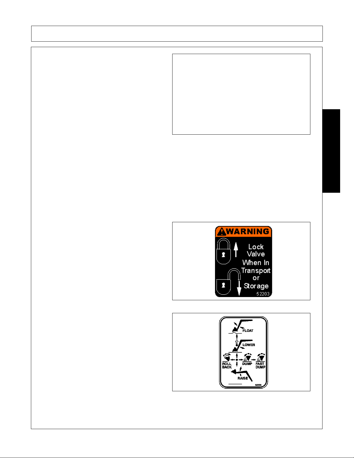
WARNING! Lock valve when in transport or
storage.
P/N 52203
Loader Positions.
P/N 52204
SAFETY
1947/2047 01/11 Safety Section 1-19
© 2011 Alamo Group Inc.
Page 24

SAFETY
Loader Safety
-Read, understand and follow the operation, warning,
and safety instructions in the Operator’s Manual.
-Equip tractor with ROPS (Roll Over Protection System)
before installing or operating the loader.
-Operate Loader only from operator’s seat with the
seatbelt securely fastened around you.
-Carry bucket low during transport for better visibility and
to avoid overturns.
-Keep bystanders 10 feet away when operating loader.
-When parking or servicing unit, lower bucket to the
ground on level hard surface, stop engine, set parking
brake, place transmission in park.
-Read and understand mounting instructions in the
operator’s manual before installing or detaching loader.
-Do not remove bucket or attachment form detached
loader.
-Do not allow riders on tractor or loader.
-Do not allow children or untrained persons to operate
loader.
D469
Crushing Hazard, Electrocution Hazard, Falling
Hazard.
D468
Crushing Hazard
D471
SAFETY
1947/2047 01/11 Safety Section 1-20
© 2011 Alamo Group Inc.
Page 25

SAFETY
DANGER! - Use ROPS and seatbelt at all times.
Add recommended rear ballast. Operate tractor at
low speeds. Failure to comply may result in serious
injury or death.
D470
Read Operator’s Manual! The operator’s manual is
located inside this canister. If the manual is
missing order one from your dealer.
P/N 00776031
SAFETY
1947/2047 01/11 Safety Section 1-21
© 2011 Alamo Group Inc.
Page 26

SAFETY
Federal Laws and Regulations
This section is intended to explain in broad terms the concept and effect of federal laws and regulations concerning
employer and employee equipment operators. This section is not intended as a legal interpretation of the law and
should not be considered as such.
Employer-Employee Operator Regulations
U.S. Public Law 91-596 (The Williams-Steiger Occupational and Health Act of 1970) OSHA
This Act Seeks:
“...to assure so far as possible every working man and woman in the nation safe and healthful working
conditions and to preserve our human resources...”
DUTIES
Sec. 5 (a) Each employer(1) shall furnish to each of his employees employment and a place of employment which are free from
recognized hazards that are causing or are likely to cause death or serious physical harm to his employees;
(2) shall comply with occupational safety and health standards promulgated under this Act.
(b) Each employee shall comply with occupational safety and health standards and all rules, regulations and
orders issued pursuant to this Act which are applicable to his own actions and conduct.
OSHA Training Requirements
Title 29, Code of Federal Regulations Part 1928.57(a)(6). www.osha.gov
Operator instructions. At the time of initial assignment and at least annually thereafter, the employer shall
instruct every employee who operates an agricultural tractor and implements in the safe operating practices
and servicing of equipment with which they are or will be involved, and of any othe r practices dictated by the
work environment.
Keep all guards in place when the machine is in operation;
Permit no riders on equipment
Stop engine, disconnect the power source, and wait for all machine movement to stop before servicing,
adjusting, cleaning or unclogging the equip ment, except where the machine must be running to be properly
serviced or maintained, in which case the employer shall instruct employees as to all steps and procedures
which are necessary to safely service or maintain the equipment.
Make sure everyone is clear of machinery before starting the engine, engaging power, or operating the
machine.
Employer Responsibilities:
To ensure employee safety during Tractor and Implement operation, it is the employer’s responsibility to:
1. Train the employee in the proper and safe operation of the Tractor and Implement.
2. Require that the employee read and fully understand the Tractor and Implement Operator’s manual.
3. Permit only qualified and properly trained employees to operate the Tractor and Implement.
4. Maintain the Tractor and Implement in a safe operational condition and maintain all shields and guards on the
equipment.
5. Ensure the Tractor is equipped with a functional ROPS and seat belt and require that the employee ope rator
securely fasten the safety belt and operate with the ROPS in the raised position at all times.
6. Forbid the employee operator to carry additional riders on the Tractor or Implement.
7. Provide the required tools to maintain the Tractor and Implement in a good safe working condition and provide the
necessary support devices to secure the equipment safely while performing repairs and service.
8. Require that the employee operator stop operation if bystanders or passersby come within 300 feet.
Child Labor Under 16 Y ear s of Age
Some regulations specify that no one under the age of 16 may ope rate power machinery. It is your responsibility to
know what these regulations are in your own area or situation. (Refer to U.S. Dept. of Labor, Employment Standard
Administration, Wage & Home Division, Child Labor Bulletin #102.)
SAFETY
1947/2047 01/11 Safety Section 1-22
© 2011 Alamo Group Inc.
Page 27

INTRODUCTION SECTION
Introduction Section 2-1
Page 28
INTRODUCTION
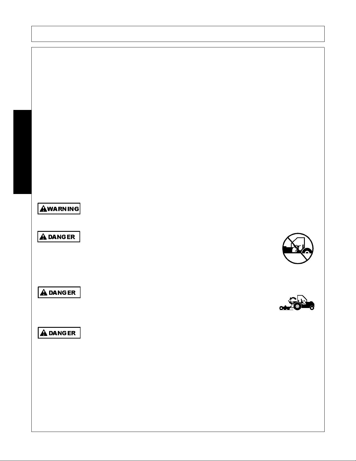
Never allow children to operate, ride on, or come close to the Tractor or
Implement. Usually, 16-17 year-old children who are mature and
responsible can operate the implement with adult supervision, if they
have read and understand the Operator’s Manuals, been trained in
proper operation of the tractor and Implement, and are physically large
enough to reach and operate the controls easily.
(SG-11)
Never allow children or other persons to ride on the Tracto r or Implement.
Falling off can result in serious injury or death.
(SG-10)
Never allow children to play on or around Tractor or Implement. Children can slip or fall off
the Equipment and be injured or killed. Inadvertent contact with controls can cause the
Implement to shift or fall crushing themselves or others.
(SG-25)
This 1947/2047 Loader is designed with care and built with quality materials by skilled workers. Proper
assembly, maintenance, and operating practices, as described in this manual, will help the owner/operator get
years of satisfactory service from the machine.
The purpose of this manual is to familiarize and instruct. The Assembly Section instructs the owner/operator in
the correct assembly of the Front End Loader using standard and optional equipment. The Parts manual is
designed to familiarize the owner/operator with replaceable parts on the Loader. This Part Manual provides
exploded assembly drawings of each Loader component illustrating each piece and the corresponding part
number.
Careful use and timely service saves extensive repairs and costly downtime losses. The Operation and
Maintenance Sections of the manual train the owner/operator how to work the Front End Loader correctly and
attend to appropriate maintenanc e. The Trouble Shooting Guide helps diagnose difficulties and offers solution
to the problems.
Safety is of primary importance to the owner/opera tor and to the ma nufa cturer. The first section of this manual
includes a list of Safety Messages, that, if followed, will help protect the operator and bystanders from injury or
death. Many of the Safety Messages will be repeated throughout the manual. The owner/operator/dealer
should know these Safety Mes sages before assembly and b e aware of the hazards of o perating this Loader
during assembly, use, and maintenance. The Safety Alert Symbol combined with a Signal Word, as seen
below, is intended to warn the owner/operator of impe nding hazards and the deg ree of possible injury faced
INTRODUCTION
when operating this machine.
It is recommended that tractor wheels be moved to the widest setting and rear ballast be
applied to increase tractor stability.
1947/2047 01/11 Introduction Section 2-2
© 2011 Alamo Group Inc.
Page 29
INTRODUCTION
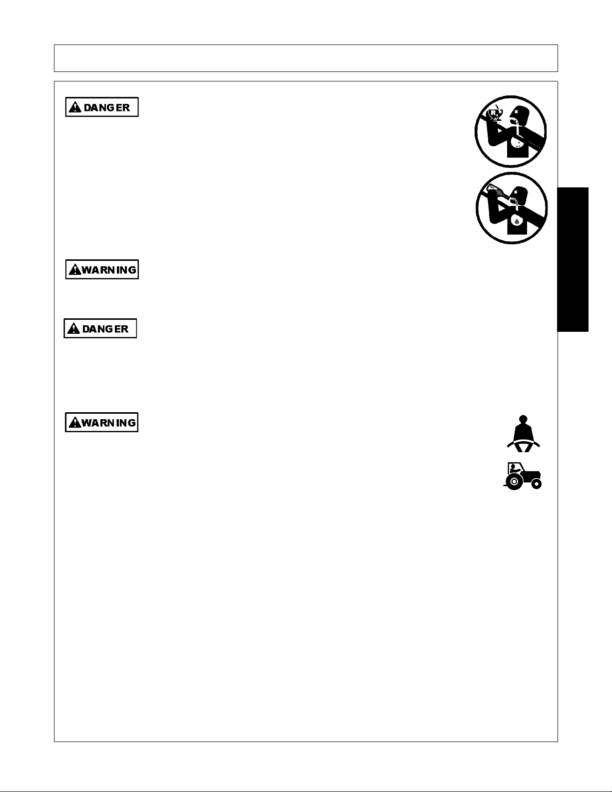
DO NOT use drugs or alcohol immediately before or while operating the
Tractor and Implement. Drugs and alcohol will affect an operator’s
alertness and coordination and therefore affect the operator’s ability to
operate the equipment safely. Before operating the Tractor or Implement,
an operator on prescription or over-the-counter medication must consult
a medical professional regard ing any side effects of the medication that
would hinder their ability to operate the Equipment safely. NEVER
knowingly allow anyone to operate this equipment when their alertne ss or
coordination is impaired. Serious injury or death to the operator or others
could result if the operator is under the influen ce of drugs or a lcohol.
(SG-27)
Engine Exhaust, some of its constituents, and certain vehicle components contain or emit
chemicals known to the state of California to cause cancer and birth defects or other
reproductive harm.
(SG-30)
Never walk or work under any raised boom or bucket. The Boom could fall and cause
serious bodily injury or death. Always lower the boom and bucket flat on the ground or
support the Boom and bucket on safety stands. Unload all hydraulic actuators prior to
performing any maintenance. To do this, set the bucket on the ground then kill the tractor
engine. Push and pull the control levers in and out several times to remove pressure. Do
not work under raised Boom or Bucket unless components are securely blocked up to
prevent inadvertent dropping.
(SBH-7)
Operate this Equipment only with a Tractor equipped with an approved rollover-protective system (ROPS). Always wear seat belts. Serious injury or
even death could result from falling off the tractor--particularly during a turnover
when the operator could be pinned under the ROPS.
(SG-7)
INTRODUCTION
1947/2047 01/11 Introduction Section 2-3
© 2011 Alamo Group Inc.
Page 30
INTRODUCTION
INTRODUCTION
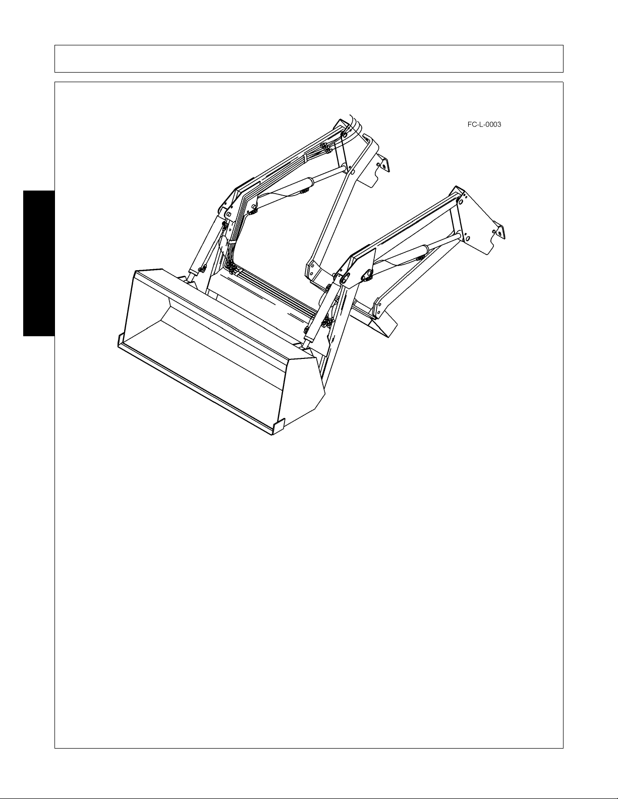
The Bush Hog 1947/2047 Loader is designed for four-wheel drive tractors. They are intended to lift only loose
materials that will fit in the bucket. All cylinders are double-acting. Parking stands support loader so tractor can
be “driven in” for quick attaching.
Front and rear, and left and right are determined by the normal direction of travel (the same as on your
automobile).
1947/2047 01/11 Introduction Section 2-4
© 2011 Alamo Group Inc.
Page 31

INTRODUCTION
Attention Owner/Operator
BEFORE OPERATING THIS MACHINE:
1. Carefully read the Operator’s Manual, completely understand the Safety Messages and instructions, and
know how to operate correctly both the tractor and implement.
2. Fill out the Warranty Card in full. Be sure to answer all questions, including the Serial Number of the
implement. Mail within 30 days of delivery date of this implement.
NOTE: Warranties are honored only if completed “Owner Registration and Warranty” forms are received by
Alamo Group within thirty days of delivery of the implement.
3. Record the Loader Model and Serial Numbers on the Warranty page. Keep this as part of the permanent
maintenance file for the implement.
INTRODUCTION
1947/2047 01/11 Introduction Section 2-5
© 2011 Alamo Group Inc.
Page 32

Page 33

ASSEMBLY AND
CONNECTING THE
LOADER SECTION
Assembly Section 3-1
Page 34
Assembly Instructions
Never allow anyone to get under the loader or attachment or to reach
through the loader lift arms when raised. Serious injury could result from
crushing or pinching by the loader or attachment.
(SL-06)
Make sure the loader is properly attached to the tractor and the retaining pins securely lock
the loader into position. Improper mounting of the loader onto the tractor can result in the
loader falling causing serious injury.
(SL-23)
Only mount the loader on a tractor that is listed on the mounting instructions. Never mount
on a tricycle steering front axle. Move the tractor front and rear wheels to the widest spacing
and add the recommended rear tractor ballast to prevent tractor tip over. Keep the tractor
tires properly inflated. Maintain at least 25% of the total Tractor and Loader weight including
the maximum load in the bucket or attachment on the rear axle. Always wear your seatbelt
and make sure the ROPS structure is fully deployed to prevent serious injury or death from
the tractor tipping over.
(SL-11)
Make sure all air is purged from the hydraulic system before using the loader. Air in the
system can cause the loader to respond sluggishly or with unexpected movement. The air
can be purged from the cylinder lines by fully cycling the cylinders several times from the
fully closed to fully open position. Sudden or unexpected movement or dropping of the
loader and attachment could result in serious injury.
(SL-32)
To avoid injury during installation of loader, do not allow bystanders within 10 feet of loader
or attachment.
Always have a heavy attachment, such as a bucket mounted on loader when it is removed
from tractor.
Always use a drift and hammer made of non-sparking material (a shot-filled mallet is
recommended) to install or remove pins. A steel hammer or drift could generate flying metal
fragments and result in injury. Always wear safety glasses when using a hammer to remove
or install pins.
Always have a heavy attachment, such as a bucket mounted on loader when it is removed
from tractor.
ASSEMBLY
ASSEMBLY
It is important not to put excessive weight on parking stands with lift cylinder retraction.
Damage may result.
1947/2047 01/11 Assembly Section 3-2
© 2011 Alamo Group Inc.
Page 35
ASSEMBLY
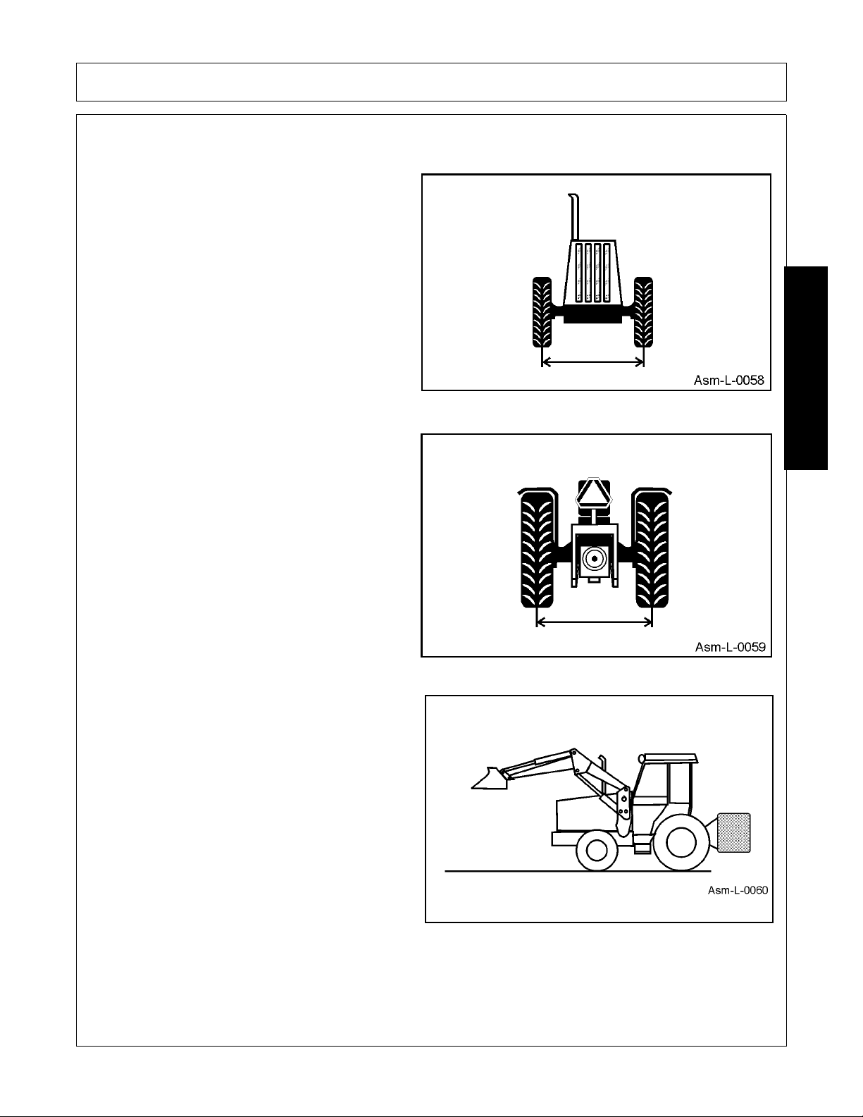
Proper Rear Ballasting and Wheel Spacing
Spread front wheels to maximum distance.
Spread rear wheels to maximum distance.
ASSEMBLY
Add rear wheel weight, rear ballast box or
implement. Make sure there is 25% of total weight
on rear axle.
1947/2047 01/11 Assembly Section 3-3
© 2011 Alamo Group Inc.
Page 36

ASSEMBLY
Installing Mounting Bracket s
Install all mounting brackets on the tractor according to instructions packed with mounting kit.
NOTE: Leave all hardware loose until the loader is completely assembled to facilitate assembly and proper
loader alignment.
Installing Side Frames
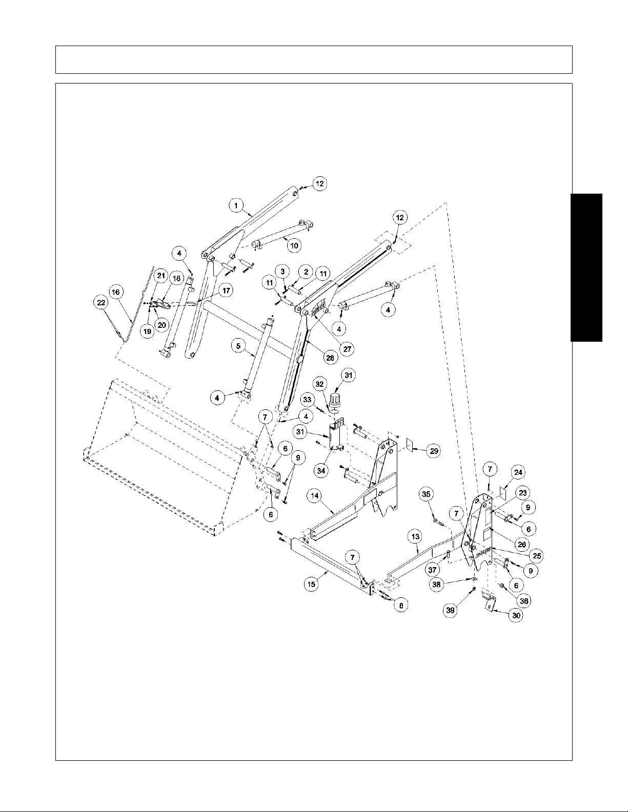
Position hinges (30) inside of side frames (13 & 14). Install 5/8 x 4 -1/2 carriage bolt s (3 5) as shown and secur e
with lock nuts (36).
Position side frames (13 & 14) over the loader mounting brackets and secure with hardware according to
instructions packed with mounting kit.
Installing Grease Fittings
Install 1/4 x 45 grease fittings (12) into the rod end of bucket cylinde rs. Install 1 /4 straight grease fittings (4) into
the tube at bucket end of lift boom arms. Also install 1/4 stra ight gr ease fitting s (4) into base and r od ends of lif t
and bucket cylinders.
Install Bucket
ASSEMBLY
Attach bucket to lift boom frame and bucket cylinders with 1” x 4-3/8” pins (6), 3/8 x 1” shoulder bolts (9) and
lock nuts (7).
1947/2047 01/11 Assembly Section 3-4
© 2011 Alamo Group Inc.
Page 37
ASSEMBLY
ASSEMBLY
1947/2047 01/11 Assembly Section 3-5
© 2011 Alamo Group Inc.
Page 38
ASSEMBLY
Installing Bucket Level Indicator
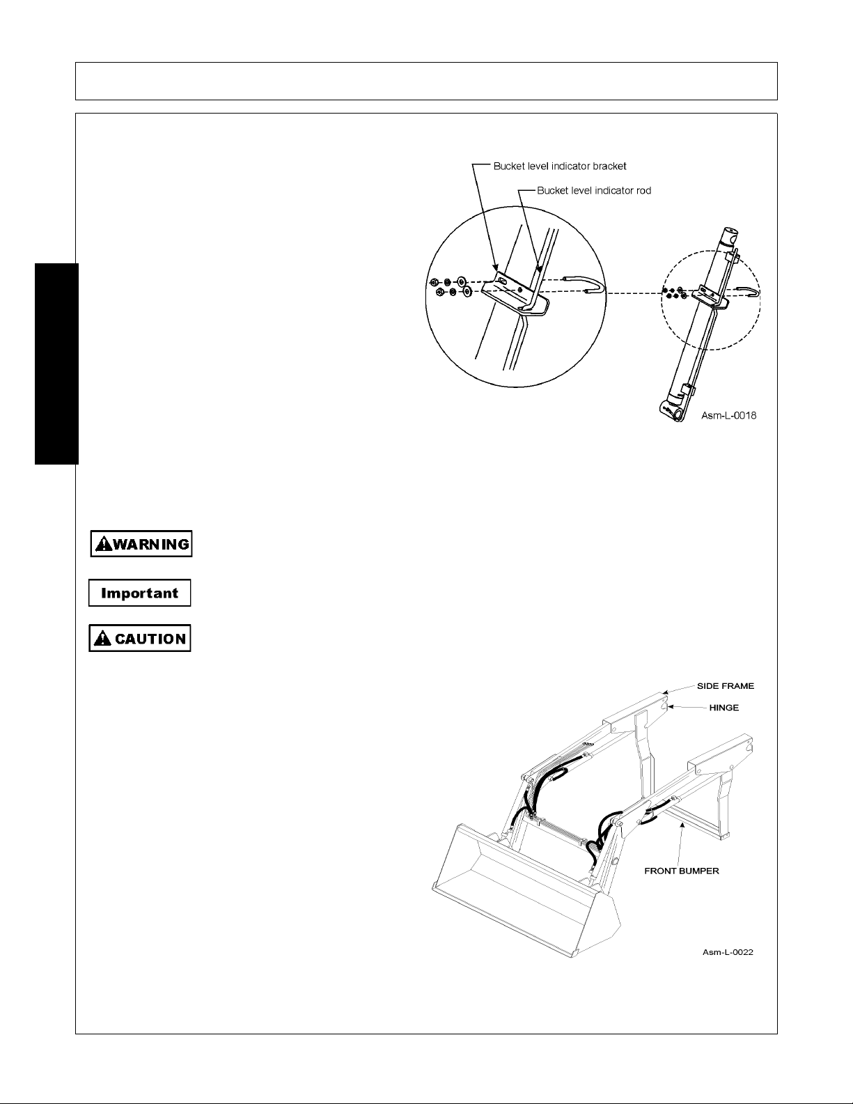
Slide bucket level indicator rod (16) into bracket
(18) and attach the other end of rod to bucket with
1/8” X 1” cotter pins (22).
Locate tractor and loader on level surface. With the
bottom of bucket resting on the surface, loos en Ubolt (17) to adjust the offset on bucket indicator rod
(16) so that it is located in the slotted hole when
bucket is level.
ASSEMBLY
Dismounting Loader and Mounting Loader to Tractor
Dismounting Loader
To avoid injury during installation of loader:
• Place loader bucket against barrier to restrict forward movement of loader.
• Do not permit bystanders within 15 feet of loader.
Loader must be equipped with a bucket or other optional attachment to dismount from
tractor.
When dismounting loader, maintain clearance between loader side frames and tractor hood
and front axle.
1. Locate tractor and loader on firm level
ground.
2. Level the bucket and lower to ground.
Engage tractor brakes and shut off tractor
engine. Move lift control lever back and forth
several times to relieve pressure in lift
cylinders.
3. Loosen bolts which clamp side frame upright s
to the mid mounting assembly. Remove bolts,
washers, and nuts.
4. Remove and save any reusable tie straps
fastening hoses from boom oil line tubes to
loader or tractor. Unhook rubber strap, if
present, secured in area of right corner of
loader bumper.
1947/2047 01/11 Assembly Section 3-6
© 2011 Alamo Group Inc.
Page 39

ASSEMBLY
5. Start tractor engine and release tractor brakes. Activate lift control lever to raise side frames up off mid
mounting assembly. Continue activating the loft control lever while gradually backing the tractor up.
Allow loader to roll off front mounting bracket until lift cylinders are fully extended and front bumper is
resting on ground. Engage tractor brakes and shut off tractor engine.
6. Move lift and bucket control lever back and forth several times to relieve pressure on lift and bucket
cylinders. Disconnect quick couplers between loader and tractor. Hang hoses over loader side frame
upright for storage.
7. Fasten bolts, washers and nuts onto hinge for storage.
8. Star t tractor engine, release brakes and slowly back the tractor away from the loader.
NOTE: Loader should be stored in a dry place. If loader is being stored for an extended period (one month or
more), a coat of grease should be applied to the cylinder shafts to prevent rusting.
Mounting Loader
Mounting is basically reverse of dismounting.
1. Slowly drive tractor into loader until the tractor front mounting brackets touch the loader side frame
channels. Engage tractor brakes and shut off tractor engine.
2. Connect quick couplers between tractor and loader by matching color coded bands.
NOTE: Make sure couplers are clean.
3. Remove bolts, nuts and washer s from hinge.
ASSEMBLY
4. Start tractor engine and release tractor brakes. If the tractor is located on a smooth surface, rotate the
bucket all the way over at this point to prevent loader from skidding forward. Continue driving loader
forward while rolling the loader on the front mounting bracket tubes until side frame uprights are fully
resting on midmounting brackets. Engage tractor brakes and shut off engine.
5. Refasten reusable tie straps in original locations. If rubber strap is used, hook one end of rubber strap
around hoses and back onto itself. Reattach other end of rubber strap to loader side frame in area of
loader front bumper.
6. Clamp hinge assembly of upright around midmounting bracket. Install bolts, washers and nuts and
securely tighten.
1947/2047 01/11 Assembly Section 3-7
© 2011 Alamo Group Inc.
Page 40

Page 41

OPERATION SECTION
Operation Section 4-1
Page 42
OPERATION
READ, UNDERSTAND, and FOLLOW the following Safety Messages. Serious injury or
death may occur unless care is taken to follow the warnings and instructions stated in the
Safety Messages. Always use good common sense to avoid hazards.
(SG-2)
Si no lee ingles, pida ayuda a alguien que si lo lea para que le traduzca las
medidas de seguridad.
(SG-3)
READ AND UNDERSTAND THE ENTIRE OPERATING INSTRUCTIONS AND SAFETY SECTION OF THIS
MANUAL AND THE TRACTOR MANUAL BEFORE ATTEMPTING TO USE THE TRACTOR AND
IMPLEMENT. If you do not understand any of the instructions, contact your nearest authorized dealer for a
full explanation. Pay close attention to all safety signs and safety messages contained in this manual and
those affixed to the implement and tractor. OPS-U- 0001
Bush Hog 1947 & 2047 LOADER
OPERATION INSTRUCTIONS
Your 1947 & 2047 Loader should now be assembled and inspected for any evidence of defective or damaged
OPERATION
parts before use. Any evidence of damage should be reported to your dealer immediately.
This section of the Operator’s Manual is designed to familiarize, instruct, and educate safe and proper loader
use to the operator. Pictures contained in this section are intended to be used as a visual aid to assist in
explaining the operation of a 1947 & 2047 loader and are not necessarily of a 1947 & 2047 loader or exact
tractor. Some pictures may show shields removed for purposes of clarity. NEVER OPERATE this implement
without all shields in place and in good operational condition. The operator must be familiar with the loader
and tractor operation and all associated safety practices before operating the loader and tractor. Proper
operation of the loader, as detailed in this manual, will help ensure years of safe and satisfactory use of the
loader.
1947/2047 01/11 Operation Section 4-2
© 2011 Alamo Group Inc.
Page 43
OPERATION
1. Standard Equipment and Specifications
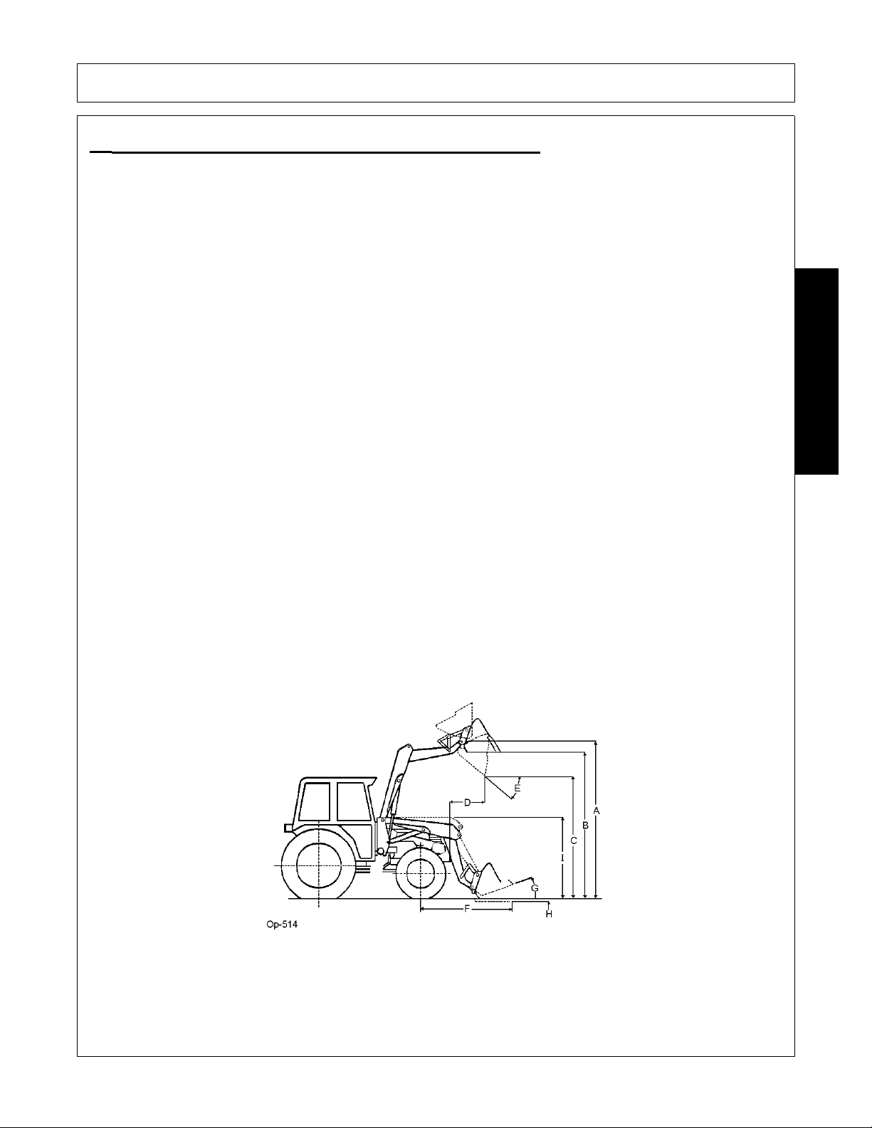
Specifications will vary with tire size, hydraulic system and bucket used. Specifications are given for a loader
equipped with a 48” bucket, external hydraulic system of 4.75 GPM with engine operating at 2800 RPM and
relief setting of 2000 PSI.
1947 2047
Horsepower Range 10-20 HP 10-20 HP
System pressure/flow rate 2000 PSI/ 5 GPM 2000 PSI/ 5 GPM
Lift Capacity to maximum height 550 lbs. 570 lbs.
Breakout force at pivot pin 1711 lbs. 1472 lbs.
Rollback force at ground line 1074 lbs. 902 lbs.
Total weight with bucket (approx.) 662 lbs. 662 lbs.
Raising time to full height 3.4 sec. 3.4 sec.
Lower time 2.2 sec. 2.2 sec.
Attachment dump time 3.3 sec. 3.3 sec.
Attachment rollback time 3.1 sec. 3.1 sec.
Hydraulic system flow 5 GPM 5 GPM
System pressure at rated flow 2000 PSI 2000 PSI
Lift Cylinders number and type two, 1-1/2 Dia. D/A two, 1-1/2 Dia. D/A
Dump Cylinders number and type two, 1-1/2 Dia. D/A two, 1-1/2 Dia. D/A
A. Maximum Lift Height at Pivot Pin 76” 77”
B. Maximum Height Under Bucket 71” 71”
C. Clearance with Bucket Dumped 57” 57”
D. Reach at Maximum Height 22” 22”
E. Maximum Dump Angle 44° 43°
F. Reach with Attachment on Ground 53” 54”
G. Attachment Rollback Angle 22° 21°
H. Digging Depth 4” 4”
I. Overall Height in Carry Position 47” 48”
OPERATION
(Manufacturers estimated specifications and design subject to change without notice.)
1947/2047 01/11 Operation Section 4-3
© 2011 Alamo Group Inc.
Page 44
2. Operator Requirements
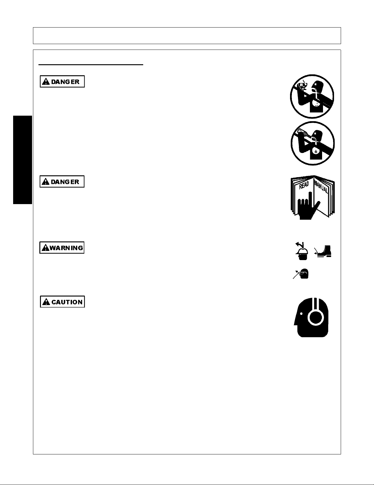
DO NOT use drugs or alcohol immediately before or while operating the
Tractor and Implement. Drugs and alcohol will affect an operator’s
alertness and coordination and therefore affect the operator’s ability to
operate the equipment safely. Before operating the Tractor or Implement,
an operator on prescription or over-the-counter medication must consult
a medical professional regard ing any side effects of the medication that
would hinder their ability to operate the Equipment safely. NEVER
knowingly allow anyone to operate this equipment when their alertne ss or
coordination is impaired. Serious injury or death to the operator or others
could result if the operator is under the influen ce of drugs or a lcohol.
(SG-27)
Never operate the Tractor or Implement until you have read and
completely understand this Manual, the Tractor Operator’s Manual, and
each of the Safety Messages found in the Manual or on the Tractor and
Implement. Learn how to stop the tractor engine suddenly in an
emergency. Never allow inexperienced or untrained personnel to
operate the Tractor or Implement without supervision. Make sure the
operator has fully read and understood the manuals prior to operation.
(SG-4)
The operator and all support personnel should wear hard hats, safety
shoes, safety glasses, and proper hearing protection at all times for
protection from injury including injury from items that may be thrown by
the equipment.
(SG-16)
PROLONGED EXPOSURE TO LOUD NOISE MAY CAUSE
PERMANENT HEARING LOSS! Tractors with or without an Implement
attached can often be noisy enough to cause permanent hearing loss.
We recommend that you always wear hearing protection if the noise in
the Operator’s position exceeds 80db. Noise over 85db over an
extended period of time will cause severe hearing loss. Noise over 90db
adjacent to the Operator over an extended period of time will cause
permanent or total hearing loss. NOTE: Hearing loss from loud noise
[from tractors, chain saws, radios, and other such sources close to the
ear] is cumulative over a lifetime without hope of natural recovery.
(SG-I7)
OPERATION
OPERATION
1947/2047 01/11 Operation Section 4-4
© 2011 Alamo Group Inc.
Page 45
OPERATION
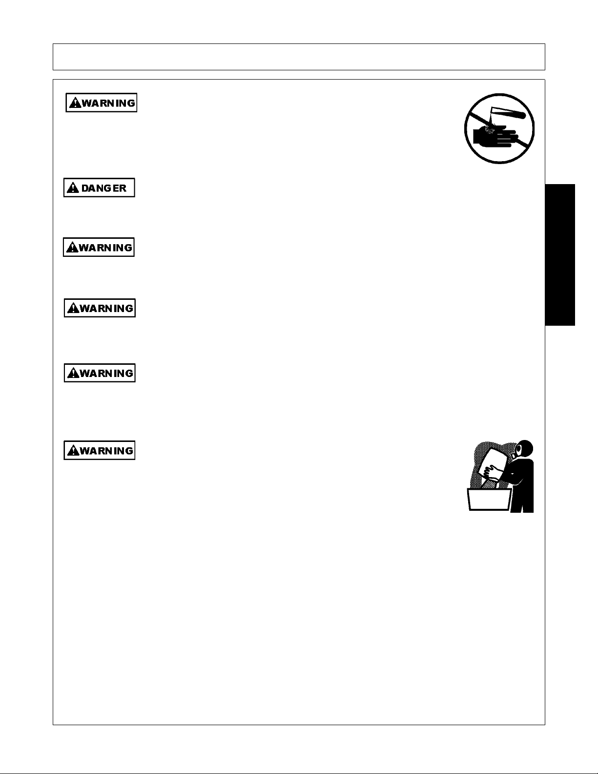
Always read carefully and comply fully with the manufacturer’s
instructions when handling oil, solvents, cleansers, and any other
chemical agent.
(SG-22)
Never run the Tractor engine in a closed building or without adequate ventilation. The
exhaust fumes can be hazardous to your health.
(SG-23)
Battery posts, terminals and related accessories contain lead and lead compounds,
chemicals known to the state of California to cause cancer, birth defects or other
reproductive harm.
(SG-31)
Prolonged operation may cause operator boredom and fatigue affecting safe operation.
Take scheduled work breaks to help prevent these potentially impaired operating
conditions. Never operate the Implement and Tractor in a fatigued or bored mental state
which impairs proper and safe operation.
(SG-32)
Use extreme caution when getting onto the Implement to perform repairs, maintenan ce and
when removing accumulated material. Only stand on solid flat surfaces to ensure good
footing. Use a ladder or raised stand to access high spots which cannot be reached from
ground level. Slipping and falling can cause serious injury or death.
(SG-33)
Use extreme care when loading, carrying or handling any agricultural
fertilizers, chemicals or biological residue. Follow the manufacturer’s
handling instructions and wear appropriate Personal Protective
Equipment including gloves, safety glasses and respirator when required.
If you are using a tractor equipped with a cab, make sure the cab is rated
for appropriate environmental exposure. Be safe and always wear proper
protection. Short or long term exposure to certain chemicals and
materials can result in serious injury or death.
(SL-19)
OPERATION
1947/2047 01/11 Operation Section 4-5
© 2011 Alamo Group Inc.
Page 46
OPERATION
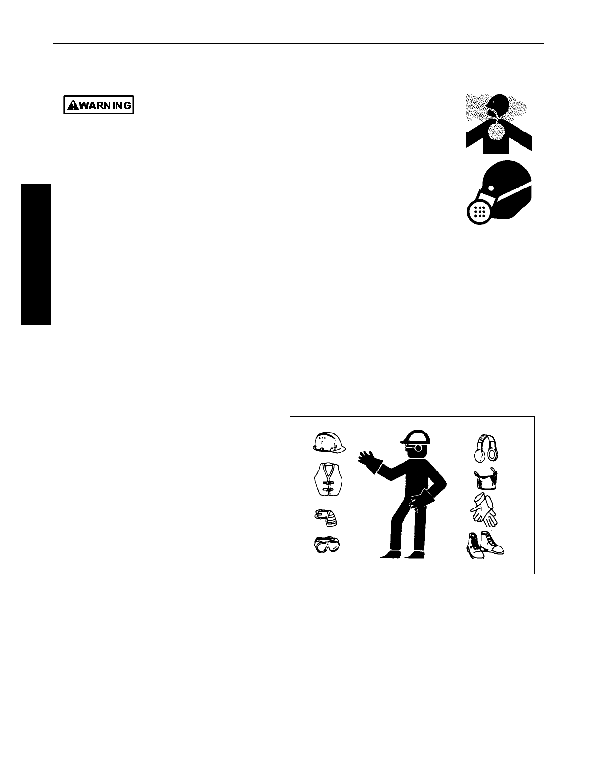
Repeated or substantial breathing of hazardous dusts, including
crystalline silica, could cause fatal or serious respiratory disease including
silicosis. Concrete, masonry, many types of rock, and various other
materials contain silica sand. California lists respirable crystalline silica as
a substance known to cause cancer. Operation of this equipment under
certain conditions may generate airborne dust particles that could contain
crystalline silica. In those conditions, personal protective equipment
including an appropriate respirator must be used. If excessive dust is
generated, a dust collection or suppression system should also be used
during operation.
(SG-41)
Safe operation of the unit is the responsibility of a qualified operator. A qualified operator has read and
understands the implement and tractor Operator’s Manuals and is experienced in implement and tractor
operation and all associated safety practices. In addition to the safety messages contained in this manual,
safety signs are affixed to the implement and tractor. If any part of the operation and safe use of this
equipment is not completely understood, consult an authorized dealer for a complete explanation.
If the operator cannot read the manuals for themselves or does not completely und erst and the opera tion of the
equipment, it is the responsibility of the supervisor to read and explain the manuals, safety practices, and
operating instructions to the operator.
Safe operation of equipment requires that the operator wear approved Personal Protective Equipment (PPE)
for the job conditions when attaching, operating, servicing, and repairing the equipment. PPE is designed to
provide operator protection and includes the following safety wear:
PERSONAL PROTECTIVE EQUIPMENT (PPE)
• Protective Eye Glasses, Goggles, or Face
Shield
•Hard Hat
• Steel Toe Safety Footwear
• Gloves
• Hearing Protection
• Close Fitting Clothing
• Respirator or Filter Mask (depends on
operating conditions) OPS-L- 0021
OPERATION
1947/2047 01/11 Operation Section 4-6
© 2011 Alamo Group Inc.
Page 47
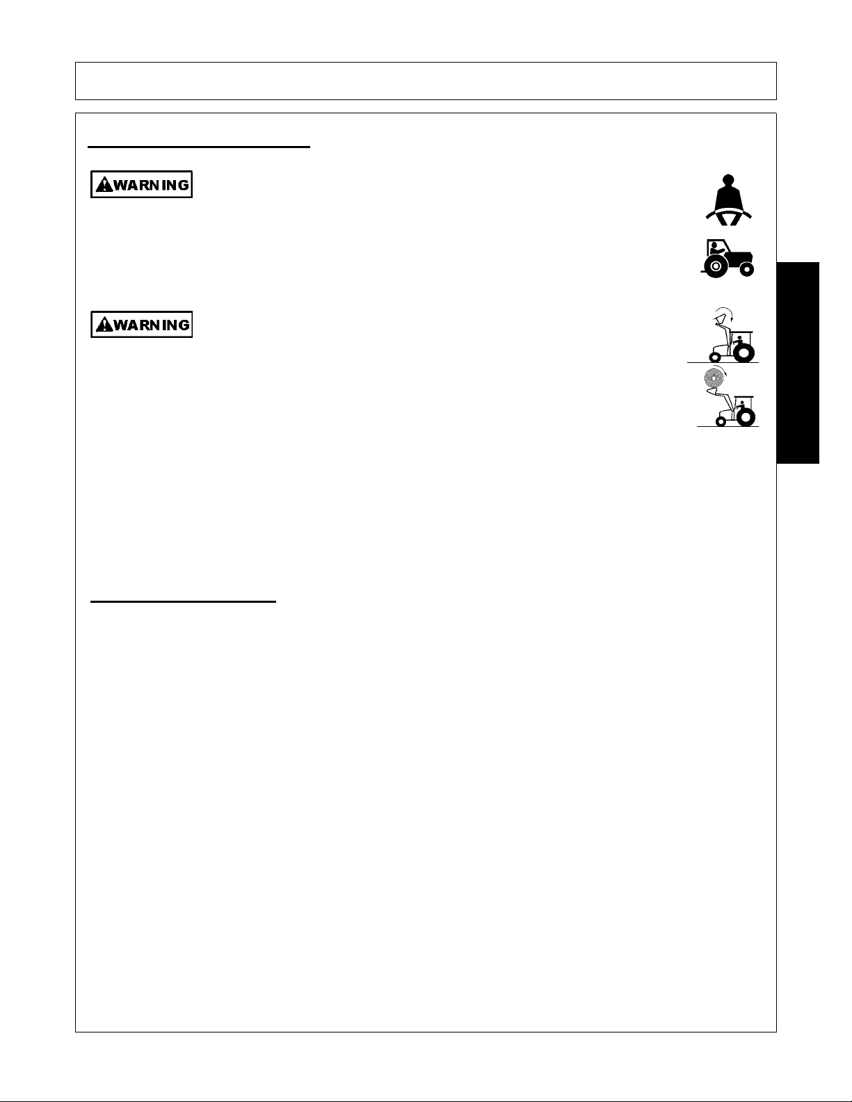
OPERATION
Operate this Equipment only with a Tractor equipped with an approved rollover-protective system (ROPS). Always wear seat belts. Serious injury or
even death could result from falling off the tractor--particularly during a turnover
when the operator could be pinned under the ROPS.
(SG-7)
For added safety when lifting loads above the height of the operator,
install a certified Falling Object Protective Structure. Shiftable loads,
round bales, large loose items, and loader attachments can fall toward
the operator resulting in serious injury or death. Falling Object Protective
Structure (FOPS) rated Cab may be obtained from the tractor dealer or
other sources.
(SL-02)
3.1 ROPS and Seat Belt
The tractor must be equipped with a Roll-Over-Protective-Structure (ROPS) (tractor cab or roll-bar) and seat
belt to protect the operator from falling off the tractor, especially during a roll over where the driver could be
crushed and killed. Only operate the tractor with the ROPS in the raised position and seat belt fastened.
Tractor models not equipped with a ROPS and seat belt should have these life saving features installed by an
authorized dealer. OPS-U- 0003
3. Tractor Requirements
Tractor Requirements and Capabilities
OPERATION
• ASABE approved Roll-Over Protective Structure (ROPS) or ROPS cab and seat belt.
• Tractor Safety Devices .......... .......Slow Moving Vehicle (SMV) emblem, lighting,
• Tractor Ballast...............................As required to maintain 25% of gross weight of tractor, loader and
bucket load on rear tires
1947/2047 01/11 Operation Section 4-7
© 2011 Alamo Group Inc.
Page 48
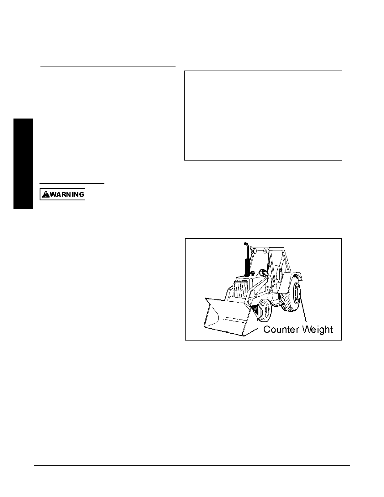
3.3 Tractor Ballast
3.2 T ractor Lighting and SMV Emblem
If the tractor will be operated near or traveled on a
public roadway it must be equipped with proper
warning lighting and a Slow Moving Vehicle (SMV)
emblem which are clearly visible from the rear of
the unit. Most tractor’s have different settings for
operating and transporting lighting. Refer to the
tractor operator’s manual for using the tractor’s
light switch and operating the turn signals.
OPS-B- 0017
To ensure tractor stability when operating add
wheel ballast or rear weights to rear tractor tires .
For better stability, use tractor with wide front axle
rather than tricycle front wheels. Move wheels to
the tractor manufacturer’s widest recommended
settings to increase stability. If 3-Point hitch
counterweights are used, they should be carried
as low as possible at all times to maximize stability .
Effective counterbalance weight at rear axle of
mounted rear equipment is determined by
multiplying actual weight of equipment by 1.50.
EXAMPLE: Equipment weighing 800 pounds,
attached to tractor, multiplied by 1.50, equals 1200
pounds of effective counterbalance weight at rear
axle.
A tractor that does not meet this criteria is
DANGEROUS and should not be operated as
upset of the unit can occur resulting in possible
serious injury and property damage. OPS-L-
0001_A
OPERATION
OPERATION
Before operating tractor and loader, add sufficient counter weight so a m inimum of 25% o f the
total weight is on the rear axle. Total weight includes weight of: tractor, loader, rated load in
bucket, and counterweight. Rated load is lift capacity at full height at 500mm forward of
bucket pivot point (See Standard Equipment and Specifications). When determining required
counterweight bucket should be at maximum forward position (bucket pivot point at the same
height as boom pivot point on mast).
1947/2047 01/11 Operation Section 4-8
© 2011 Alamo Group Inc.
Page 49
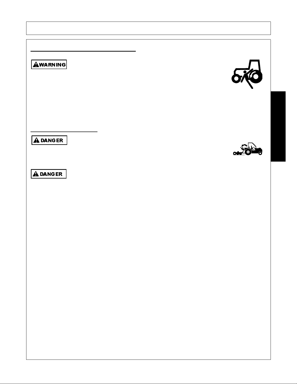
OPERATION
Do not mount or dismount the Tractor while the t ractor is moving . Mount
the Tractor only when the Tractor and all moving parts are
completelystopped.
(SG-12)
Before getting onto the tractor, the operator must read and completely understand the implement and tractor
operator manuals. If any part of either manual is not completely understood, consult an authorized dealer for
a complete explanation. OPS-L- 0022
Never allow children or other persons to ride on the Tracto r or Implement.
Falling off can result in serious injury or death.
(SG-10)
Never grasp control levers when mounting the machine. (SBH-4)
Use both hands and equipped handrails and steps for support when boarding the tractor. Never use control
levers for support when mounting the tractor. Seat yourself in the operator’s seat and secure the seat belt
around you.
Never allow passengers to ride on the tractor or attached equipment. Riders can easily fall off and be
seriously injured or killed from falling off and being ran over. It is the operator’s responsibility to forbid all extra
riders at all times. OPS-L- 0023
4. Getting On and Off the Tractor
4.1 Boarding the Tractor
OPERATION
1947/2047 01/11 Operation Section 4-9
© 2011 Alamo Group Inc.
Page 50
4.2 Dismounting the T ractor
BEFORE leaving the tractor seat lower the implement, set the parking
brake and/or set the tractor transmission in parking gear, disengage the
PTO, stop the engine, remove the key, and wait for all moving parts to
stop. Place the tractor shift lever into a low range or parking gear to
prevent the tractor from rolling. Never dismount a Tractor that is moving
or while the engine is running. Operate the Tractor controls from the
tractor seat only.
(SG-9)
Before dismounting the tractor and loader lower the loader to the ground or
onto solid support blocks. Engage the loader valve travel lock to prevent
inadvertent movement of the valve controls causing the loader to suddenly
move and drop. Sudden dropping of the loader and attachment could
result in serious injury.
(SL-05)
Before dismounting, park the tractor and implement on a reasonably level surface, apply the parking brake,
idle the engine down, disengage the PTO, and lower the implement to the ground. Shut down the tractor
engine according to the operator’s manual, remove the key, and wait for all motion to completely stop. Never
leave the seat until the tractor , its engine and all moving parts have come to a complete stop.
Use hand rails and steps when exiting the tractor. Be careful of your step and use extra caution when mud,
ice, snow or other matter has accu mu la te d o n t he st eps or han d r ails . Us e a ll ha n dr ails an d s te ps for su ppor t
and never rush or jump off the tractor. OPS-L- 0024
OPERATION
OPERATION
1947/2047 01/11 Operation Section 4-10
© 2011 Alamo Group Inc.
Page 51
5. Starting the Tractor
Never run the Tractor engine in a closed building or without adequate ventilation. The
exhaust fumes can be hazardous to your health.
(SG-23)
Start tractor only when properly seated in the Tractor seat. Starting a
tractor in gear can result in injury or death. Read the Tractor operators
manual for proper starting instructions.
(SG-13)
The operator must have a complete underst anding of the placement, function, and operationa l use of all tractor
controls before starting the tractor. Review the tractor operator’s manual and consult an authorized dealer for
tractor operation instructions if needed.
Essential Tractor Controls:
• Locate the ignition switch
• Locate the light control lever
• Locate the engine shut off control
• Locate the engine throttle control
• Locate the brake pedals and the clutch
• Locate the parking brake
• Locate the PTO control
• Locate the 3-point hitch control lever
• Locate the hydraulic remote control levers
Before starting the tractor ensure the following:
• Conduct all pre-start operation inspection and serv ice according to the tractor operator’s manual.
• Make sure all guards, shields, and other safety devices are securely in place.
• The parking brake is on.
• The 3-point hitch control lever is in the lowered position.
• The hydraulic remote control levers are in the neutral positio n.
• The tractor transmission levers are in park or neutral.
Refer to the tractor owner’s manual for tractor starting procedures. Only start the tractor while seated and
belted in the tractor operator’s seat. Never bypass the ignition switch by short circuiting the starter solenoid.
After the tractor engine is running, avoid accident al contact with the tractor transmission to prevent sudden and
unexpected tractor movement. OPS-L-0025
OPERATION
OPERATION
1947/2047 01/11 Operation Section 4-11
© 2011 Alamo Group Inc.
Page 52

OPERATION
Periodically inspect all moving parts for wear and replace when
necessary with authorized service parts. Look for loose fasteners, worn
or broken parts, and leaky or loose fittings. Make sure all pins have
cotter pins and washers. Serious injury may occur from not maintaining
this machine in good working order.
(SG-21)
Before each use, a pre-operation inspection and service of the implement and tractor must be performed.
This includes routine maintenance and scheduled lubrication, inspecting that all safety devices are equipped
and functional, and performing needed repairs. DO NOT operate the unit if the pre-operation inspection
reveals any condition affecting safe operation. Perform repairs and replacement of damaged and missing
parts as soon as noticed. By performing a thorough pre-operation inspection and service, valuable down time
and repair cost can be avoided. OPS-L-0026
6.1 Tractor Pre-Operation Inspection/Service
Refer to the tractor operator’s manual to ensure a
complete pre-operation inspection and scheduled
service is performed according to the
manufacturers recommendations. The following
are some of the items that require daily service and
inspection:
• Tire condition/air pre ssure
• Wheel lug bolts
• Steering linkage
• PTO shield
• SMV sign is clean and visible
• Tractor’s lights are clean and function al
• Tractor Seat belt is in good condition
• Tractor ROPS is in good condition
• ROPS is in the raised position
• No tractor oil leaks
• Radiator free of debris
• Engine oil level and condition
• Engine coolant level and condition
• Power brake fluid level
• Power steering fluid level
• Fuel condition and level
• Sufficient lubrication at all lube points
6. Pre-Operation Inspection and Service
OPERATION
Loader Pre-Operation Inspection and Service
1947/2047 01/11 Operation Section 4-12
© 2011 Alamo Group Inc.
Page 53
OPERATION
Periodically inspect all moving parts for wear and replace when
necessary with authorized service parts. Look for loose fasteners, worn
or broken parts, and leaky or loose fittings. Make sure all pins have
cotter pins and washers. Serious injury may occur from not maintaining
this machine in good working order.
(SG-21)
Avoid contact with hot surfaces including hydraulic oil tanks, pumps, motors, valves and
hose connections. Relieve hydraulic pressure before performing maintenance or repairs.
Use gloves and eye protection when servicing hot components. Contact with a hot surface
or fluid can cause serious injury from burns or scalding.
(SG-34)
Do not operate this Equipment with hydraulic oil or fuel leaking. Oil
and fuel are explosive and their presence could present a hazard. Do
not check for leaks with your hand! High-pressure oil streams from
breaks in the line could penetrate the skin and cause tissue damage
including gangrene. To check for a hose leak, SHUT the unit ENGINE
OFF and remove all hydraulic pressure. Wear oil imp ene trab le glo ves ,
safety glasses and use Cardboard to check for evidence of oil leaks. If
you suspect a leak, REMOVE the HOSE and have it tested at a Dealer.
If oil does penetrate the skin, have the injury treated immediately by a
physician knowledgeable and skilled in this procedure.
(SG-15)
OPERATION
Before operation, a complete inspection and service is required to ensure the loader is in a good and safe
working condition. Damaged and/or broken parts should be repaired and/or replaced immediately. To ensure
the loader is ready for operation, conduct the following. OPS-L-0027
1947/2047 01/11 Operation Section 4-13
© 2011 Alamo Group Inc.
Page 54
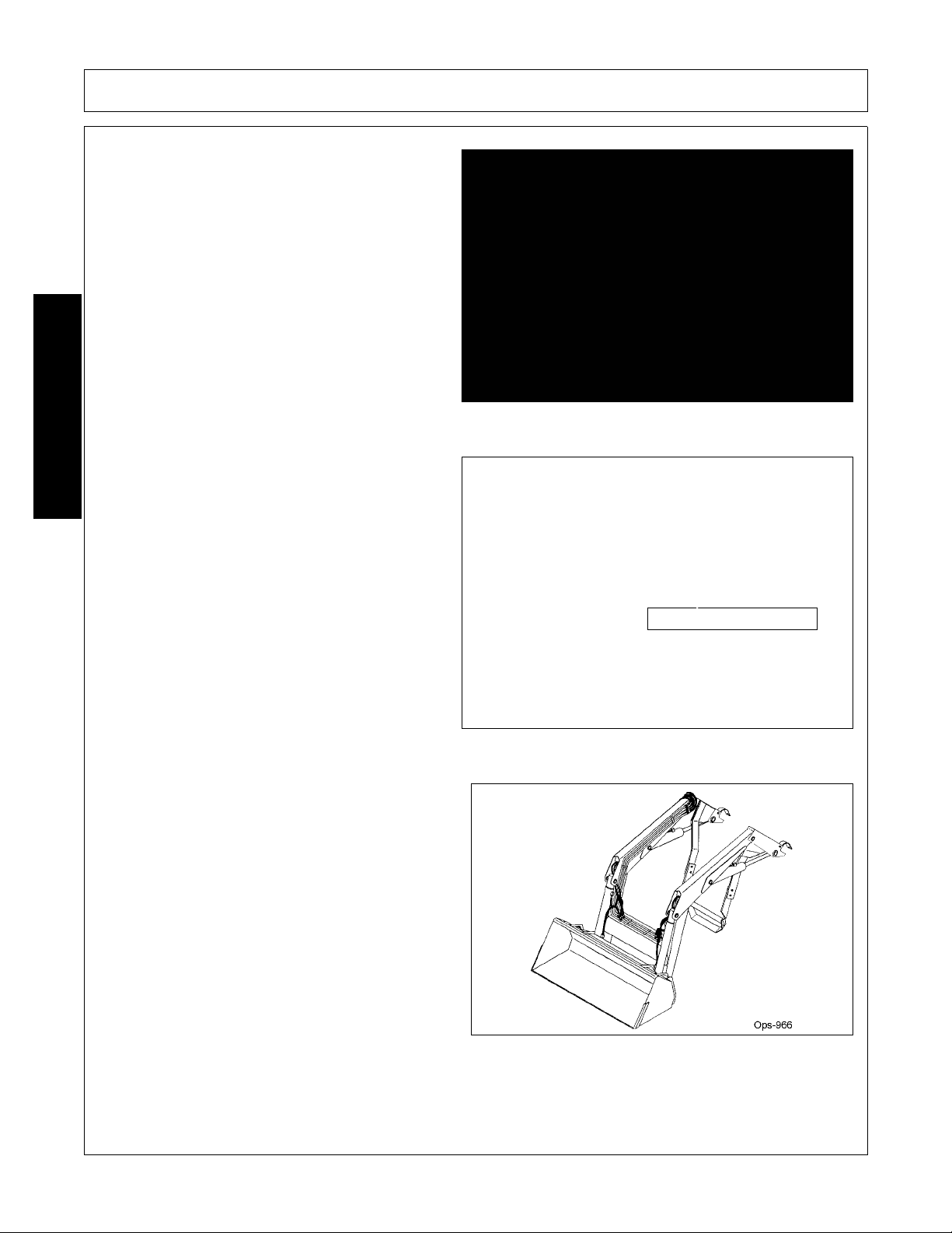
OPERATION
The operator’s manual and safety signs affixed on
the unit contain important instructions on the safe
and proper use of the equipment. Maintain these
important safety features on the implement in good
condition to ensure the information is available to
the operator at all times.
• Ensure the manual canister is secured to the
equipment with the operator’s manual inside.
• Ensure all safety signs are in plac e an d leg ible.
Replace missing, damaged, and illegible
decals. OPS-U- 0011
MOUNT ASSEMBLY
• Inspect condition of mounting frame weldment.
• Ensure all bolts and screws are in position and
are properly torqued.
• Ensure all pins are in place and fastened with
screws.
• Ensure frame is properly mounted to tractor
and hardware is properly installed and
tightened. OPS-L-0004_A
Mount Frame Assembly
LOADER BOOM ASSEMBLY
• Inspect condition of each arm section weldment
• Ensure all pins are in place.
• Ensure all bolts and screws are properly
installed.
• Check condition of bushings at boom pivot
points.
• Ensure each hydraulic cylinder is installed and
retained correctly. Ensure the proper size pins
are used to retain the cylinders in place and are
secured properly. OPS-L-0005_B
OPERATION
1947/2047 01/11 Operation Section 4-14
© 2011 Alamo Group Inc.
Page 55
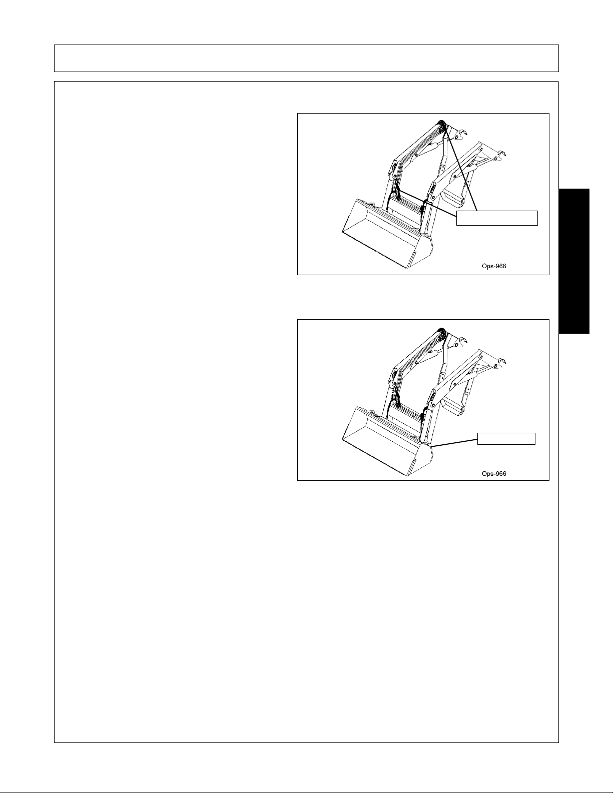
OPERATION
HYDRAULIC LINE INSPECTION
• Check for hydraulic leaks along hoses,
cylinders and fittings. IMPORTANT: DO NOT
use your hands to check for oil leaks. Use a
piece of heavy paper or cardboard to check for
hydraulic oil leaks.
• Inspect the condition of the valve weldment.
• Ensure fitting is properly connected
• Inspect condition of bushings. OPS-L-0018_B
Hydraulic Hoses
BUCKET INSPECTION
• Ensure all pins are in place.
• Ensure each hydraulic cylinder is installed and
retained correctly. Ensure the proper size pins
are used to retain the cylinders in place and are
secured properly.
• Inspect the condition of the bucket lug
weldments.
• Inspect condition of bushings.
OPS-L-0007_B
Bucket Pins
OPERATION
1947/2047 01/11 Operation Section 4-15
© 2011 Alamo Group Inc.
Page 56
OPERATION
Tractor PRE-OPERATION Inspection
Tractor ID#:________________________Make:________________________
Date:______________________________Shift:________________________
Before conducting the inspection, make sure the tractor engine is off, all
rotation has stopped and the tractor is in park with the parking brake
engaged. Make sure the implement is resting on the ground or securely
blocked up and all hydraulic pressure has been relieved.
Operator’s Signature:___________________________________________________
Item
Condition at
Start of Shift
Specific Comments if
not O.K.
The flashing lights function properly
The SMV Sign is clean and visible
The tires are in good condition with proper pressure
The wheel lug bolts are tight
The tractor brakes are in good condition
The steering linkage is in good condition
There are no visible oil leaks
The hydraulic controls function properly
The ROPS or ROBS Cab is in good condition
The seatbelt is in place and in good condition
The 3-point hitch is in good condition
The drawbar pins are securely in place
The PTO master shield is in place
The engine oil level is full
The brake fluid level is full
The power steering fluid level is full
The fuel level is adequate
The engine coolant fluid level is full
The radiator is free of debris
The air filter is in good condition
DO NOT OPERATE an UNSAFE TRACTOR or IMPLEMENT
OPERATION
1947/2047 01/11 Operation Section 4-16
© 2011 Alamo Group Inc.
Page 57
OPERATION
FRONT END LOADER PRE-OPERATION Inspection
Front End Loader ID#_______________Make____________________
Date_____________________________Shift____________________
Before conducting the inspection, make sure the tractor engine is off, all
rotation has stopped and the tractor is in park with the parking brake
engaged. Make sure the Loader is resting on the ground or securely blocked
up and all hydraulic pressure has been relieved.
Operator’s Signature:
Item
Condition at
Start of Shift
Specific Comments if
not O.K.
The Operator’s Manual is in the Canister on the Loader
All Safety Decals are in place and legible
The Mounting frame bolts are in place and tight
The Loader Arms are securely retained in frame mounts
The Loader connection bolts & pins are tight
There are no cracks in Loader Arms or Mounts
The Attachment pins are in place and secure
The Bucket Quick Attach pins pass through the attachment
The Bucket Quick Attach control levers are in the lock position
The Hydraulic Cylinder pins are secured
The Hydraulic hose connections are tight
The Hydraulic Valve hose connections are tight
There are no leaking or damaged hoses
There is no evidence of Hydraulic leaks
The Control Valve Lock functions correctly
The Pivot Pins are properly lubricated
The Loader Storage Stands are in good condition
DO NOT OPERATE an UNSAFE TRACTOR or FRONT END LOADER
OPERATION
Driving the Tractor and Loader
1947/2047 01/11 Operation Section 4-17
© 2011 Alamo Group Inc.
Page 58
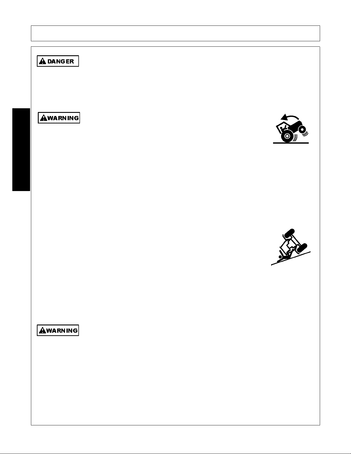
OPERATION
This Implement may be wider than the Tractor. Be careful when operating or transporting
this equipment to prevent the Implement from running into or striking sign posts, guard rails,
concrete abutments or other solid objects. Such an impact could cause the Implement and
Tractor to pivot violently resulting in loss of steering control, serious injury, or even death.
Never allow the Implement to contact obstacles.
(S3PT-12)
Transport only at speeds where you can maintain control of the
equipment. Serious accidents and injuries can result from operating this
equipment at high speeds. Understand the Tractor and Implement and
how it handles before transporting on streets and highways. Make sure the Tractor steering
and brakes are in good condition and operate properly.
Before transporting the Tractor and Implement, determine the proper transport speeds for
you and the equipment. Make sure you abide by the following rules:
Test the tractor at a slow speed and increase the speed slowly. Apply the Brakes smoothly
to determine the stopping characteristics of the Tractor and Implement. As you increase
the speed of the Tractor the stopping distance increases. Determine the maximum
transport speed not to exceed 20 mph (30 kph) for transporting this equipment.
Test the equipment at a slow speed in turns. Increase the speed through the turn only after
you determine that the equipment can be operated at a higher speed. Use extreme care
and reduce your speed when turning sharply to prevent the tractor and implement from
turning over. Determine the maximum turning speed for you and this equipment before
operating on roads or uneven ground.
Only transport the Tractor and Implement at the speeds which allow you to properly control
the equipment.
Be aware of the operating conditions. Do not operate the Tractor with weak or faulty brakes
or worn tires. When operating down a hill or on wet or rain slick roads, the braking distance
increases: use extreme care and reduce you r speed. When operating in traffic always use
the Tractor’s flashing warning lights and red uce your speed. Be a ware of traf fic around yo u
and watch out for the other guy.
(SG-19)
Your driving vision may be reduced or impaired by the tractor, cab, or implement. Before
driving on public roadways identify any limited vision areas, and make adjustments to your
operating position, mirrors, and the implement transport position so that you can clearly
see the area where you will be traveling, and any traffic that may approach you. Failure to
maintain adequate vision of the public roadway and traffic can result in serious injury or
even death.
(STI-10)
OPERATION
1947/2047 01/11 Operation Section 4-18
© 2011 Alamo Group Inc.
Page 59
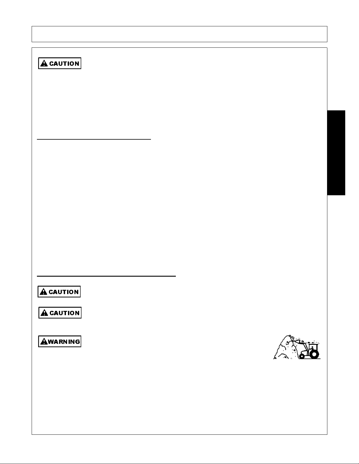
OPERATION
Use extra care when turning or stopping. Allow for increased length and weight of added
loader . The lo ade r ad ds five to six fee t of le ngt h in front of the tractor and si gnificant weigh t.
Allow extra distance when stopping or turning. Do not allow loader or attachment to conta ct
solid objects.
(SL-07)
Start off driving at a slow speed and gradually increase your speed while maintaining complete control of the
tractor and loader. Moving slowly at first will also prevent the tractor from rearing up and loss of steering
control. The tractor should never be operated at speeds that cannot be safely handled or which will prevent
the operator from stopping quickly during an emergency. If the power steering or engine ceases operating,
stop the tractor immediately as the tractor will be difficult to control.
Perform turns with the tractor and loader at slow speeds to determine how the tractor with an attached
implements handles a turn. Determine the safe speed to maintain proper control of the tractor when making
turns. When turning with an imple ment, the overall working length of the unit is increased. Allow additional
clearance for the loader when turning.
To avoid overturns, drive the tractor with care and at safe speeds, especially when operating over rough
ground, crossing ditches or slopes, and turning corners. Tractor rear wheel spacing should be increased
when operating on inclines or rough ground to reduce the possibility of tipping.
Use extreme caution when operating on steep slopes. Keep the tractor in a low gear when going downhill.
DO NOT coast or free-wheel downhill. OPS-L-0030
Use extreme care when piling material above 6 feet high. Material
could shift and fall onto the operator or by standers. The material could
crush or suffocate the operator or bystander resulting in serious injury
or death.
(SL-17)
Safe tractor transport requires the operator possess a thorough knowledge of the model being operated and
precautions to take while driving with an attached implement. Ensure the tractor has the capacity to handle the
weight of the implement and the tractor operating controls are set for safe transport. To ensure safety while
driving the tractor with an attached implement, review the following. OPS-L- 0028
6.2 Driving the T ractor and Loader
OPERATION
7. Operating the Tractor and Loader
Do not attempt to lift loads in excess of loader capacity.
Operating loader on a hillside is dangerous. Extreme care is recommended. Keep bucket
as low as possible.
1947/2047 01/11 Operation Section 4-19
© 2011 Alamo Group Inc.
Page 60
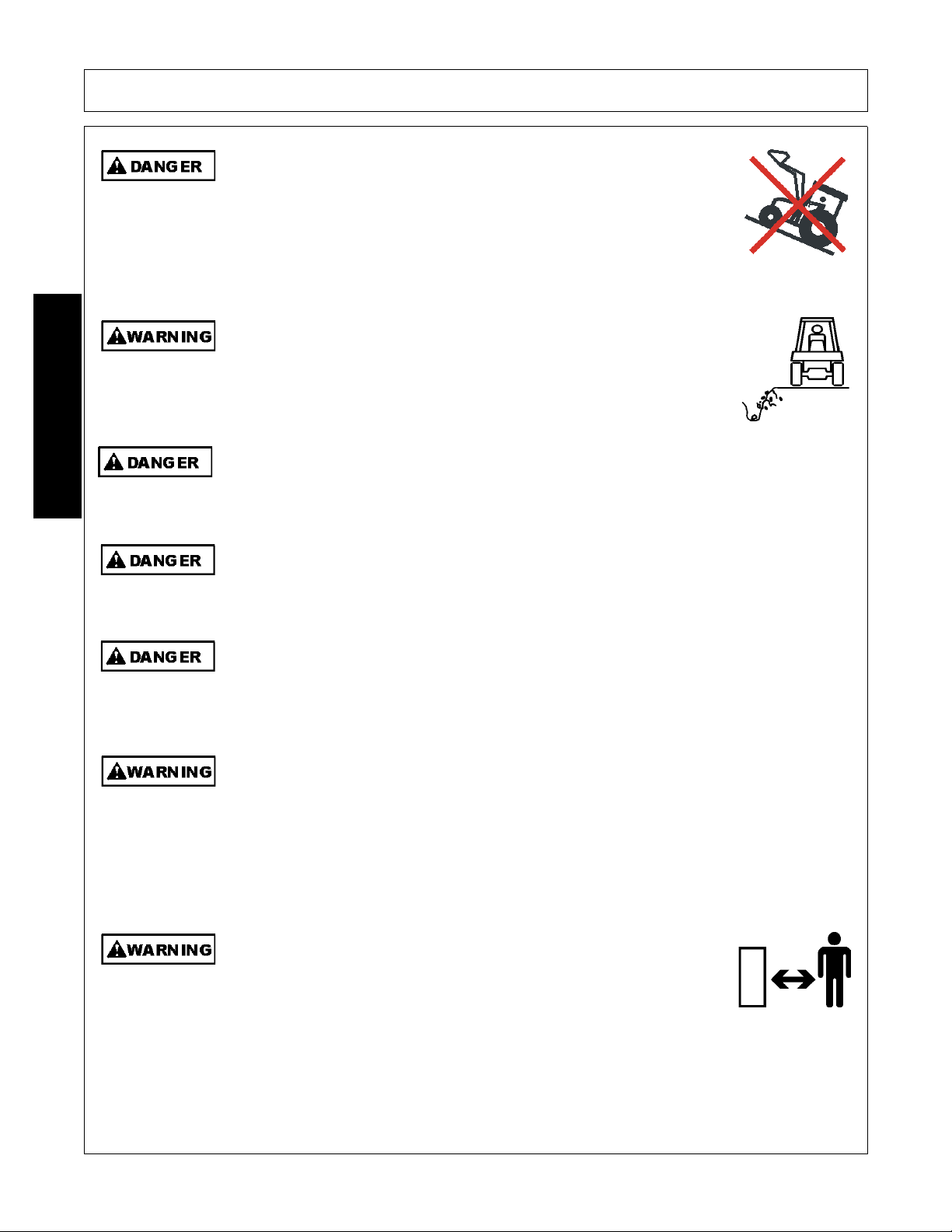
OPERATION
Do not raise the loader on a hillside. Do not transport across a slope with
a raised loader. When the loader is raised, the center of gravity of the
tractor and loader is raised increasing the potential for the tractor to tip
over. Tractor wheel contact with any wash out, drop off or the ground
obstruction with a raised loader could result in the tractor tipping over and
causing serious bodily injury.
(SL-21)
Do not operate or raise the loader near the edge of a ditch or whe re loose
soil can give way and allow the tractor to tip over. Keep the tractor tires
away from loose soil or the edge of a drop off. Always wear your seatbelt
when operating the loader to reduce the possibility of serious injury from a
tractor tip over or roll over.
(SL-24)
The Boom is designed only to position and operate the Bucket which is att ached to it. Never
attempt to lift, pull, or push other solid objects with the boom or bucket. Serious injury could
result from a structural failure when the Boom is used for purposes other than those for
which it was designed.
(SBH-9)
Operate the Tractor and/or Implement control s only while properly seated in the Tractor seat
with the seat belt securely fastened around you. Inadvertent movement of the Tractor or
Implement may cause serious injury or death.
(SG-29)
DO NOT operate this Implement on a Tractor that is not properly maintained. Should a
mechanical or Tractor control failure occur while operating, immediately shut down the
Tractor and perform repairs before resuming operation. Serious injury and possible death
could occur from not maintaining this Implement and Tractor in good operating condition.
(SG-36)
Do Not operate this equipment in areas where insects such as bees may attack you and/or
cause you to lose control of th e equipment. If you must enter in such areas, use a tractor
with an enclosed Cab and close the windows to prevent insects from entering. If a tractor
cab is not available, wear suitable clothing including head, face, and hand protection to
shield you from the insects. Attacking insects can cause you to lose control of the tractor,
which can result in serious injury or death to you o r bystanders. Never dismount a moving
tractor.
(SG-40)
Keep bystanders 10 feet away from the tractor and loader while
operating. The bystanders could enter the path of the tractor or items
could fall from the loader resulting in serious injury to the bystander.
(SL-01)
OPERATION
1947/2047 01/11 Operation Section 4-20
© 2011 Alamo Group Inc.
Page 61
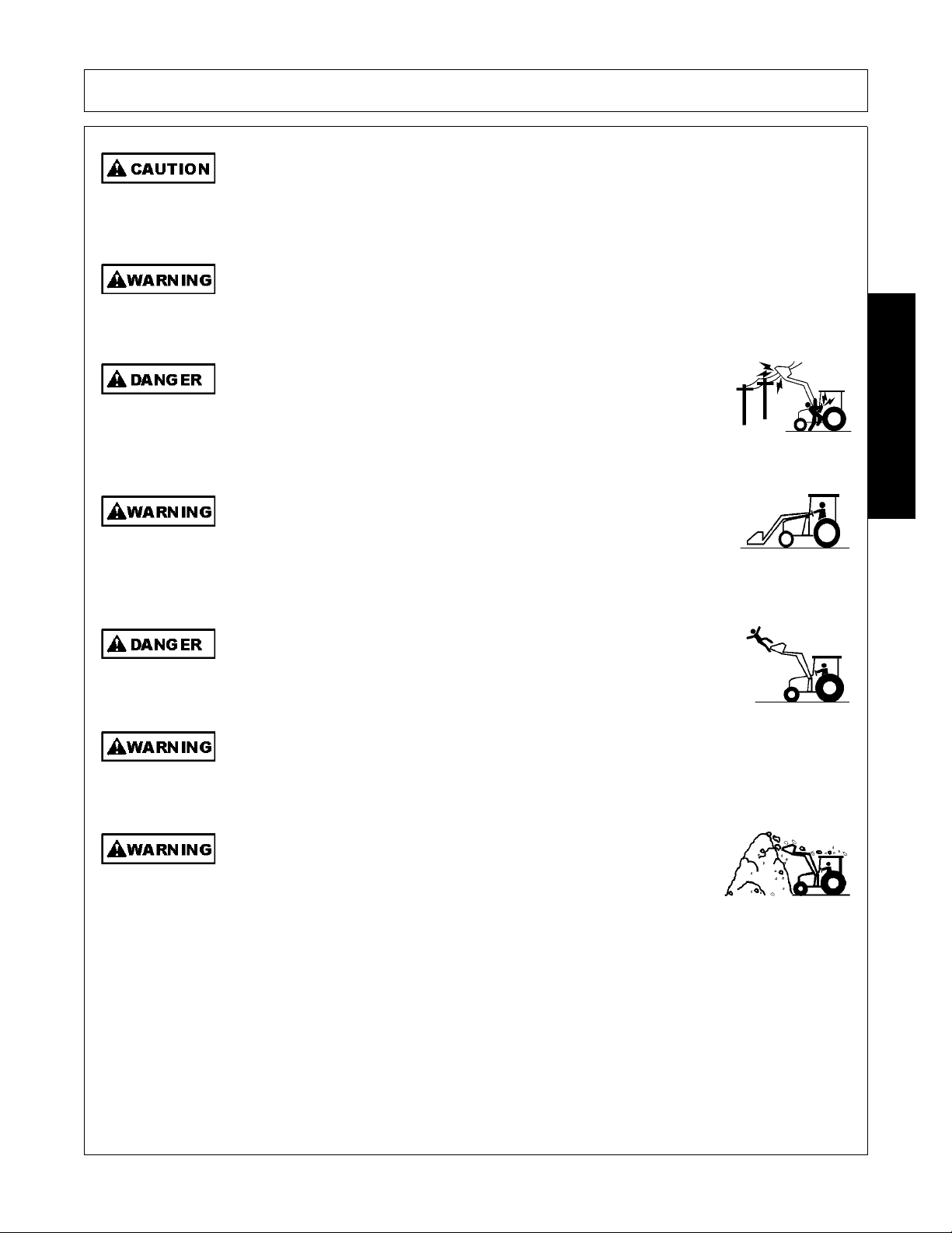
OPERATION
Use extra care when turning or stopping. Allow for increased length and weight of added
loader . The lo ade r ad ds five to six fee t of le ngt h in front of the tractor and si gnificant weigh t.
Allow extra distance when stopping or turning. Do not allow loader or attachment to conta ct
solid objects.
(SL-07)
Do not raise the loader into an overhead structure or allow a raised attachment to contact
overhead structures. Sudden or unexpected contact with an overhead structure could result
in serious injury.
(SL-08)
Do not let the loader or attachment contact electrical power lines. Contact
with electrical power lines can result in serious injury or electrocution. If
the loader attachment contacts a power line remain in the tractor seat
until the power has been shut off. Stepping off the tractor can permit
electrical current to pass through the body resulting in electrocution.
(SL-09)
Carry the loader and attachment low when transporting to reduce the
potential of the tractor tipping over. Transport on slopes only at slow
speeds and use gradual turning angles. Tractor wheel contact with any
wash out, drop off or ground obstruction with a raised loader could result
in the tractor tipping over and causing serious injury.
(SL-12)
Do not work from the loader or at tachments. Do now allow any riders on
the loader, tractor or attachments. Falling off the loader could result in
serious injury and/or tractor run over.
(SL-14)
Do not operate the loader from the ground. Operate the tr actor and loader only while seated
in the tractor seat with the seatbelt fastened. The loader could fall crushing a person
resulting in serious injury or death.
(SL-16)
Use extreme care when piling material above 6 feet high. Material
could shift and fall onto the operator or by standers. The material could
crush or suffocate the operator or bystander resulting in serious injury
or death.
(SL-17)
OPERATION
1947/2047 01/11 Operation Section 4-21
© 2011 Alamo Group Inc.
Page 62
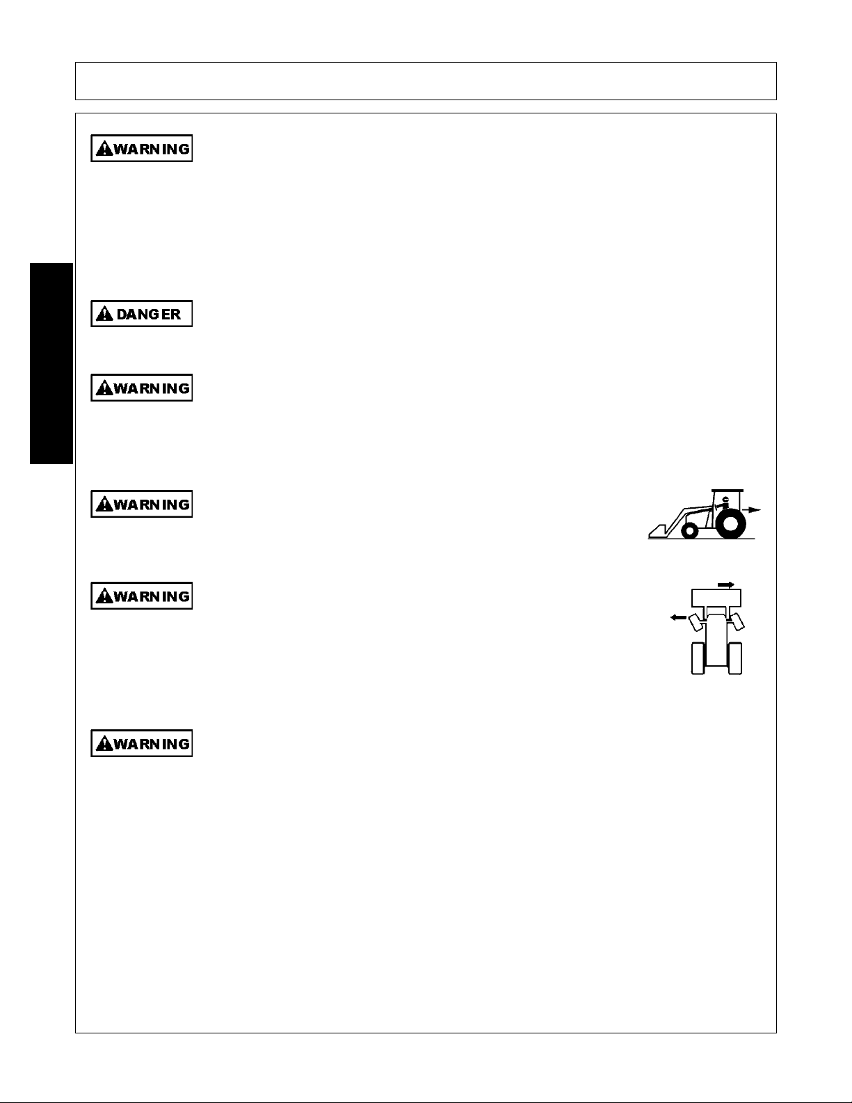
OPERATION
Know before you DIG. Call 888-258-0808 and request that all buried utilities locations be
identified before digging in unfamiliar ground. Do not let the loader or attachment contact
buried electrical power lines, utilities or gas lines. Contact with electrical power lines can
result in serious bodily injury or electrocution. If the loader contacts a power line, remain in
the tractor seat until the power has been shut off. Stepping off the tractor can permit
electrical current to pass through the body resulting in electrocution.
(SL-18)
Do not use loader as a jack to raise the tractor tires off the ground. The loader could fail
causing the tractor and loader to fall to the ground resulting in serious injury.
(SL-25)
Use extreme care when loading, transporting or dumping loads that impair or partially block
the operator’s line of sight. Know where you are traveling. Make sure no bystanders are in
the area of travel. If a bystander assists in pr oviding guidance, make sure they are not in the
path of travel. Keep all bystanders 25 feet away from travel path.
(SL-29)
Always look behind you before backing up. Make sure you are looking
in the direction of travel. A bystander could walk behind the tractor.
Running into a bystander can result in serious inju ry or death.
(SL-30)
Some tractors are equipped with a “Super Steer” front axle. When a
loader is mounted to this type of tractor, the bucket will shift in the
opposite direction from which the wheels are turned. Maximum shift will
be approximately 8 inches and most noticeable when the tractor is
stationary. Sudden or unexpected movement of the loader and
attachment could result in serious injury to the operator or bystanders.
(SL-33)
Operate the tractor and loader only in conditions where you have clear visibility in daylight
or with adequate artificial lighting. Never operate in darkness or fo gg y condition s wher e you
cannot clearly see at least 100 feet in front and to the sides of the tractor. Make sure you
can clearly see bystanders, ditche s, steep slopes, drop-offs, overhead obstructions, power
lines, and debris or obstruction in the tr avel path. If you are unable to clearly see these
types of items discontinue operating. Contact with unseen vehicles, bystanders,
obstructions, or drop-offs can cause serious injury.
(SL-35)
OPERATION
1947/2047 01/11 Operation Section 4-22
© 2011 Alamo Group Inc.
Page 63
OPERATION
Never leave the Implement and Power Unit unattended while the Implement is in the raised
position. Accidental operation of a lifting lever or a hydraulic failure may cause the
implement to suddenly fall causing serious injury or possible death to anyone who might
inadvertently be under the Implement. Lower the implement carefully to the gr ound. Do not
put hands or feet under lifted componen ts.
(SPU-3)
Before dismounting the tractor and loader, lower the loader to the ground or onto solid
support blocks. Sudden dropping of the loader and attachment could result in serious
injury.
(SL-38)
Make sure the hydraulic quick disconnects are fully seated into the connections. Do not use
the loader if the hydraulic connection is leaking. Leaking oil could allow the loader to fall
resulting in a serious crushing injury.
(SL-22)
If the loader valve controls fail to functions properly discontinue use of the tractor and
loader until the controls are properly repaired. Sudden or unexpected movement or
dropping of the loader and attachment could result in seriou s injury.
(SL-31)
Make sure all air is purged from the hydraulic system before using the loader. Air in the
system can cause the loader to respond sluggishly or with unexpected movement. The air
can be purged from the cylinder lines by fully cycling the cylinders several times from the
fully closed to fully open position. Sudden or unexpected movement or dropping of the
loader and attachment could result in serious injury.
(SL-32)
Do not raise the loader on a hillside. Do not transport across a slope with
a raised loader. When the loader is raised, the center of gravity of the
tractor and loader is raised increasing the potential for the tractor to tip
over. Tractor wheel contact with any wash out, drop off or the ground
obstruction with a raised loader could result in the tractor tipping over and
causing serious bodily injury.
(SL-21)
OPERATION
Always have a heavy attachment, such as a bucket mounted on loader when it is removed
from tractor.
It is important not to put excessive weight on parking stands with lift cylinder retraction.
Damage may result.
1947/2047 01/11 Operation Section 4-23
© 2011 Alamo Group Inc.
Page 64
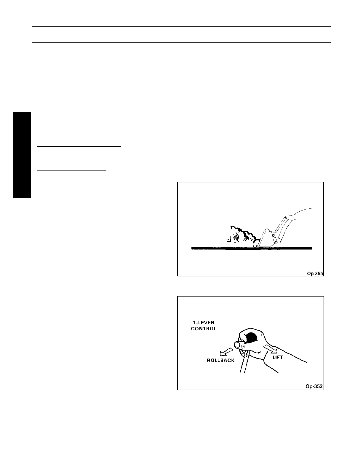
OPERATION
THE OPERATOR MUST COMPLETELY UNDERSTAND HOW TO OPERATE THE TRACTOR AND
IMPLEMENT AND ALL CONTROLS BEFORE ATTEMPTING TO OPERATE. The operator must read and
understand the Safety and Operation Sections of the implement and tractor operator’s manuals. These
manuals must be read and explained to any operator who cannot read. Never allow someone to operate the
implement and tractor without complete operating instructions.
Before starting any operation, the operator must become familiar with the area to be worked in and any
obstacles and hazards contained within to ensure safety to the operator, bystanders, and equipment. Special
attention should be paid to foreign debris, ro ugh terr ain, steep slopes, and p assersby and an imals in the area.
OPS-L-0033
7.1 Operating the Loader
The following text and illustrations offer suggested loader and tractor operating techniques.
FILLING THE BUCKET
Approach and enter the pile with a level bucket.
OPERATION
Loaders with 1-lever control, ease lever back
toward you to lift and roll back bucket. With series
valve, prevent loader stall by not lifting and rolling
back at the same time.
1947/2047 01/11 Operation Section 4-24
© 2011 Alamo Group Inc.
Page 65
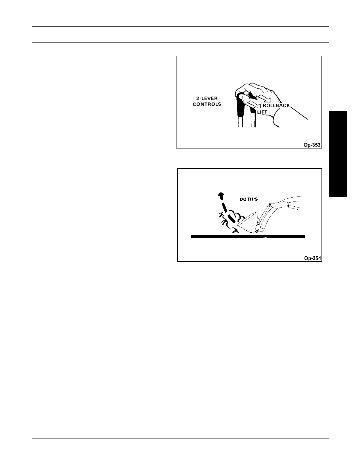
OPERATION
Lift and roll back of bucket will increase efficiency
because...
OPERATION
1947/2047 01/11 Operation Section 4-25
© 2011 Alamo Group Inc.
Page 66
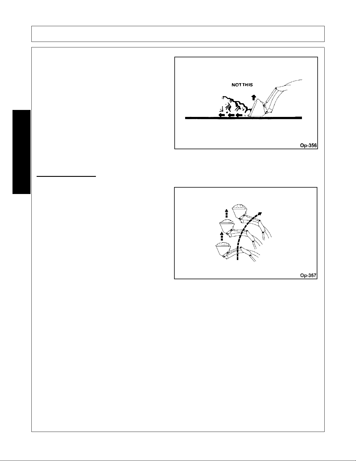
OPERATION
A level bucket throughout the lifting cycle resists
bucket lift and increases breakaway effort.
NOTE: Do not be concerned if the bucket is not
completely filled during each pass. Maximum
productivity is determined by the amount of m aterial
loaded in a given period of time. Time is lost if two
or more attempts are made to fill the bucket on
each pass.
LIFTING THE LOAD
OPERATION
When lifting the load, keep the bucket positioned to
avoid spillage. Loader has mechanical self leveling
of attachment in both raise and lower cycle.
Attachment can be adjusted by using bucket
cylinders.
1947/2047 01/11 Operation Section 4-26
© 2011 Alamo Group Inc.
Page 67
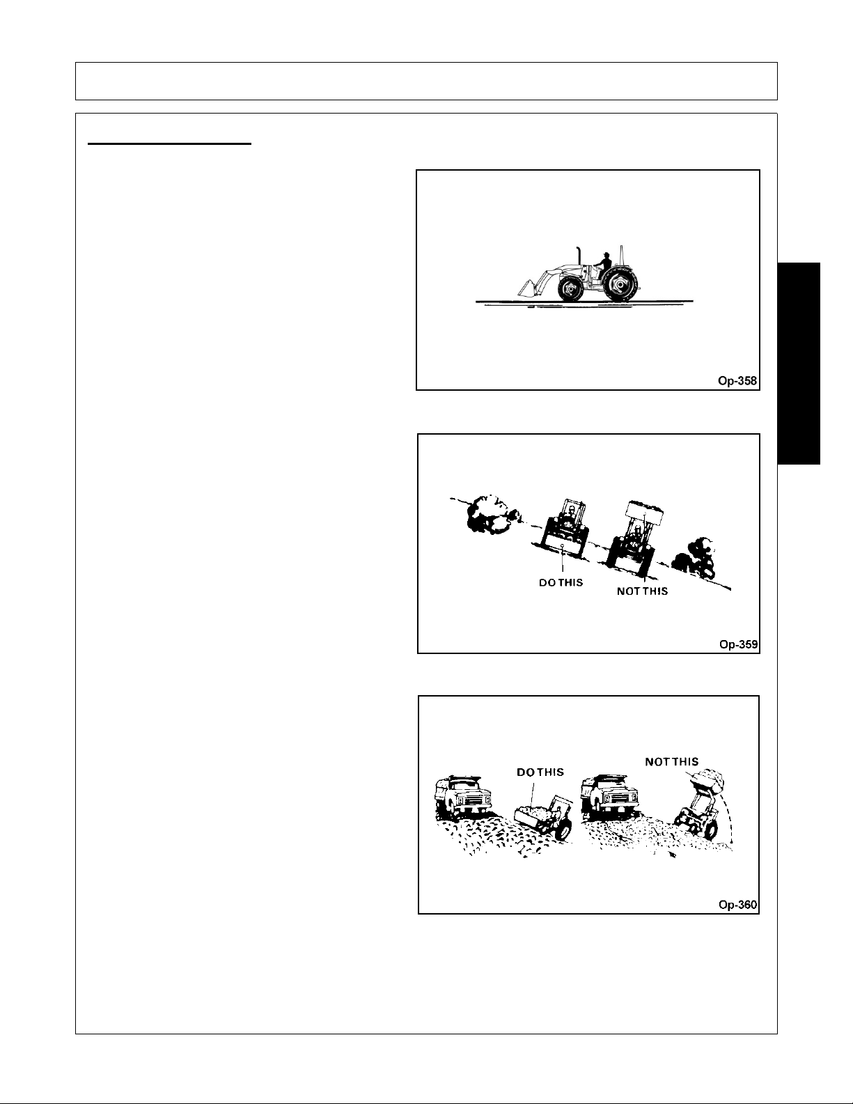
OPERATION
CARRYING THE LOAD
Position bucket just below tractor hood for
maximum stability and visibility, whether bucket is
loaded or empty.
Use extreme care when operating loader on a
slope, keep bucket as low as possible. This keeps
center of gravity low and will provide maximum
stability.
OPERATION
When transporting the load, keep bu cket as low as
possible, to avoid tipping, in case a wheel drops in a
rut.
1947/2047 01/11 Operation Section 4-27
© 2011 Alamo Group Inc.
Page 68
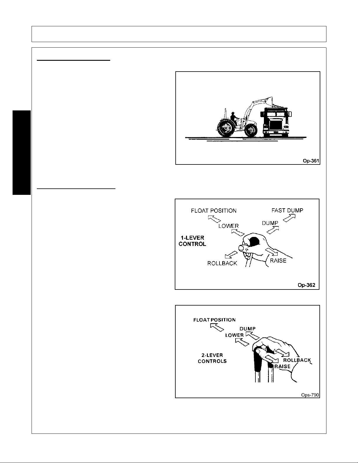
OPERATION
DUMPING THE BUCKET
Lift bucket high enough to clear side of vehicle.
Move tractor in as close as possible to side of
vehicle, then dump bucket.
OPERATION
LOWERING THE BUCKET
After bucket is dumped, back away from vehicle
while lowering and rolling back bucket.
1947/2047 01/11 Operation Section 4-28
© 2011 Alamo Group Inc.
Page 69
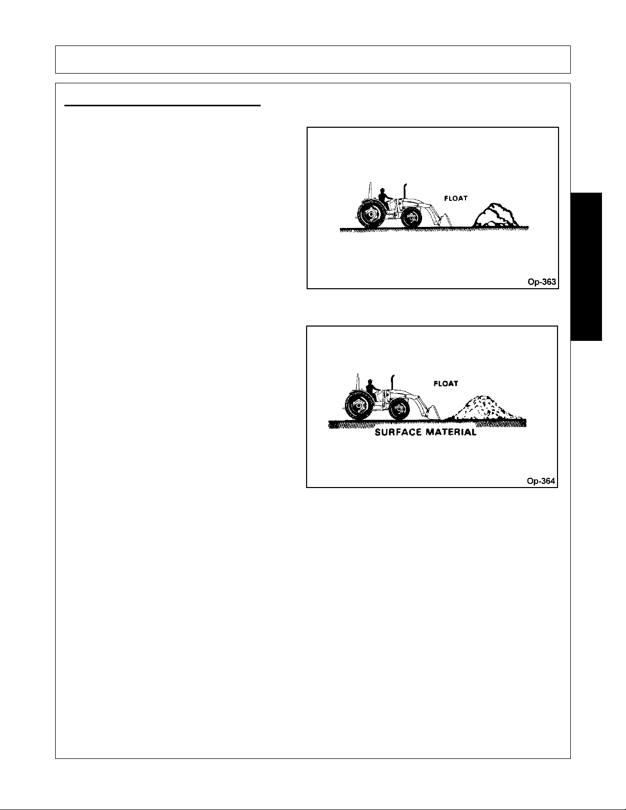
OPERATION
OPERATING WITH FLOAT CONTROL
During hard surface operation, keep bucket level
and put lift control in float position to permit bucket
to float on working surface. If hydraulic down
pressure is exerted on bucket, it will wear faster
than normal.
Float will also prevent mixing of surface material
with stockpile material. Float position will reduce the
chance of surface gouging whe n removing snow or
other material.
OPERATION
1947/2047 01/11 Operation Section 4-29
© 2011 Alamo Group Inc.
Page 70
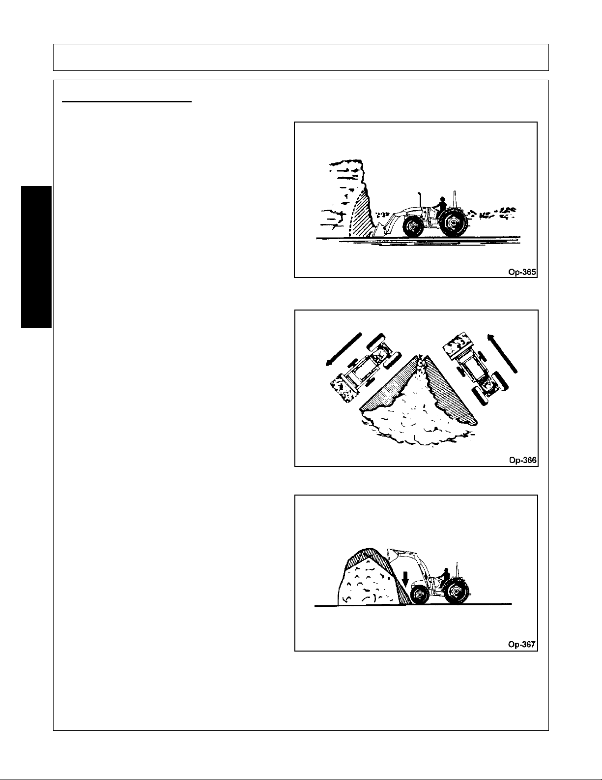
OPERATION
LOADING FROM A BANK
Choose a forward gear that provides sufficient
ground speed for loading.
Exercise caution when undercutting high banks.
Dirt slides can be dangerous. Load from as low as
possible for maximum efficiency. Loader lift and
breakaway capacity diminish as loading height is
increased.
OPERATION
Side cutting is a good technique for cutting down a
big pile.
If the pile sides are too high and liable to cause
cave-in, use loader to break down the sides until a
slot can be cut over the top.
1947/2047 01/11 Operation Section 4-30
© 2011 Alamo Group Inc.
Page 71
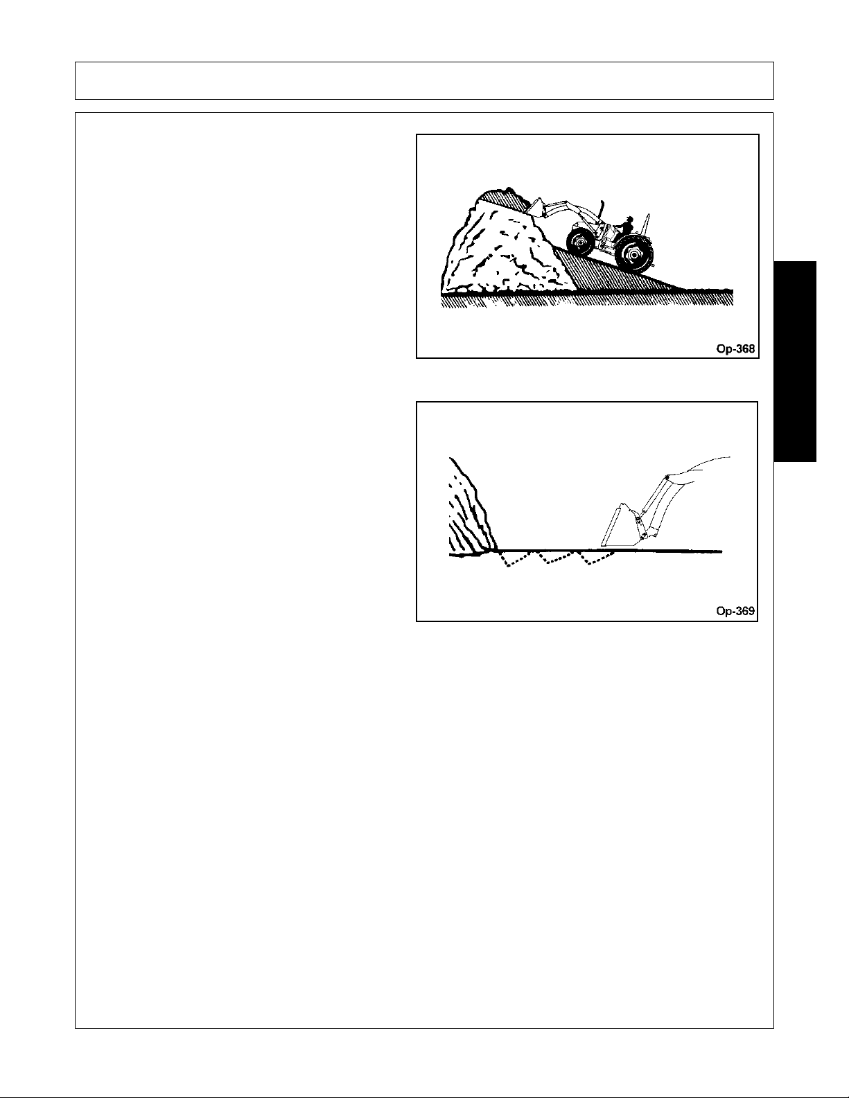
OPERATION
Another method for large dirt piles is to build a ram p
approach to the pile.
It is important to keep the bucket level when
approaching a bank or pile. This will help prevent
gouging the work area.
OPERATION
1947/2047 01/11 Operation Section 4-31
© 2011 Alamo Group Inc.
Page 72
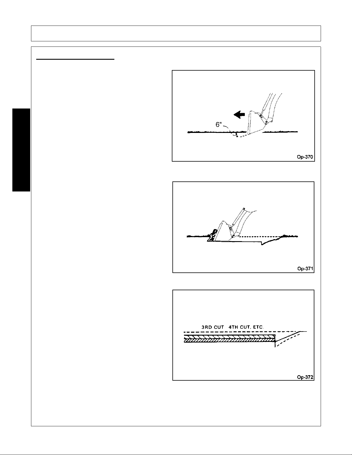
OPERATION
PEELING AND SCRAPING
Use a slight bucket angle, travel forward and hold
lift control forward to start the cut. Make a short 5 to
8 foot angle cut and break out cleanly.
OPERATION
With bucket level, start a cut at notch approximately
2 inches deep. Hold depth by feathering bucket
control to adjust cutting lip up or down. When front
tires enter the notch, adjust lift cylinder to maintain
proper depth.
Make additional passes until desired depth is
reached. During each pass, use only bucket con trol
while working depth. This will allow you to
concentrate on controlling bucket angle to maintain
a precise cut.
1947/2047 01/11 Operation Section 4-32
© 2011 Alamo Group Inc.
Page 73
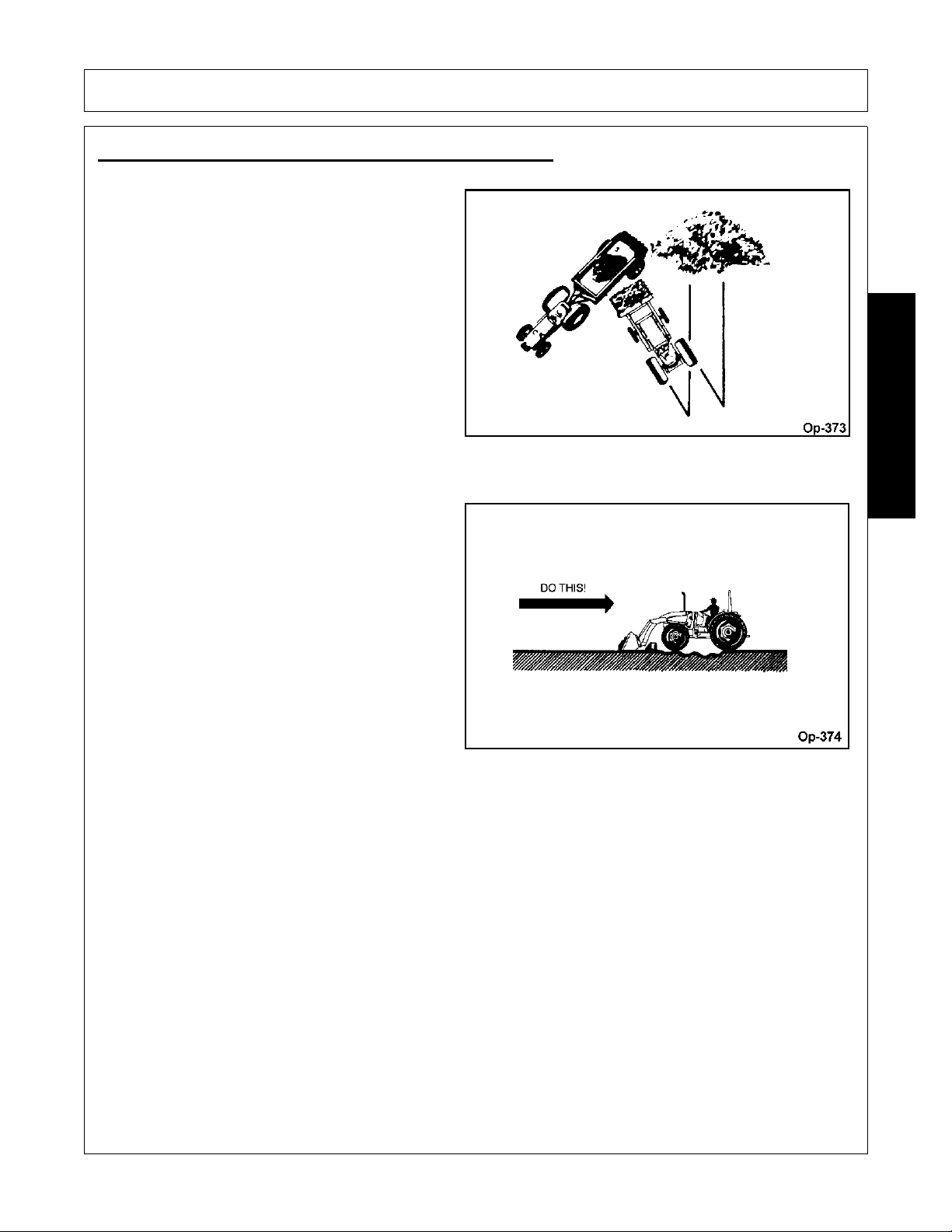
OPERATION
LOADING LOW TRUCKS OR SPREADERS FROM A PILE
For faster loading, minimize angle of turn and
length of run between pile and spreader. Back
grade occasionally with a loaded bucket to keep
working surface free of ruts and holes. Also, hold lift
control forward so full weight of bucket is scraping
ground.
Do not roll bucket over and attempt to backgrade.
This type of use can cause severe ove rloading of
bucket cylinders when fully extended, possibly
causing bucket cylinder rods to become bent.
OPERATION
1947/2047 01/11 Operation Section 4-33
© 2011 Alamo Group Inc.
Page 74
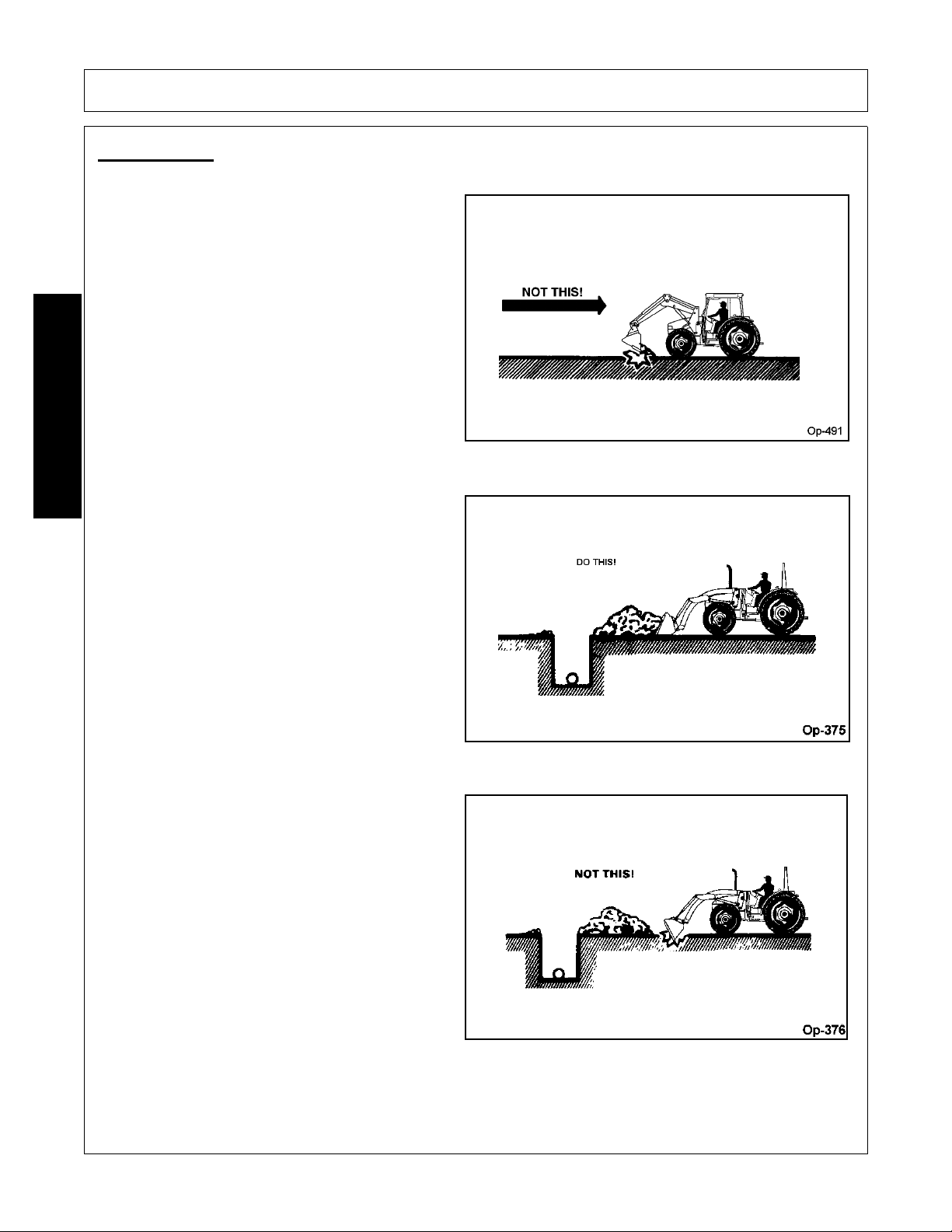
OPERATION
BACKFILLING
Approach pile with a level bucket.
OPERATION
Poor methods actually move no more dirt and make
it more difficult to hold a level grade.
Do not use bucket in dumped position for
bulldozing. This method, shown above, will impose
severe shock loadings on dump linkage, bucket
cylinder and tractor.
1947/2047 01/11 Operation Section 4-34
© 2011 Alamo Group Inc.
Page 75
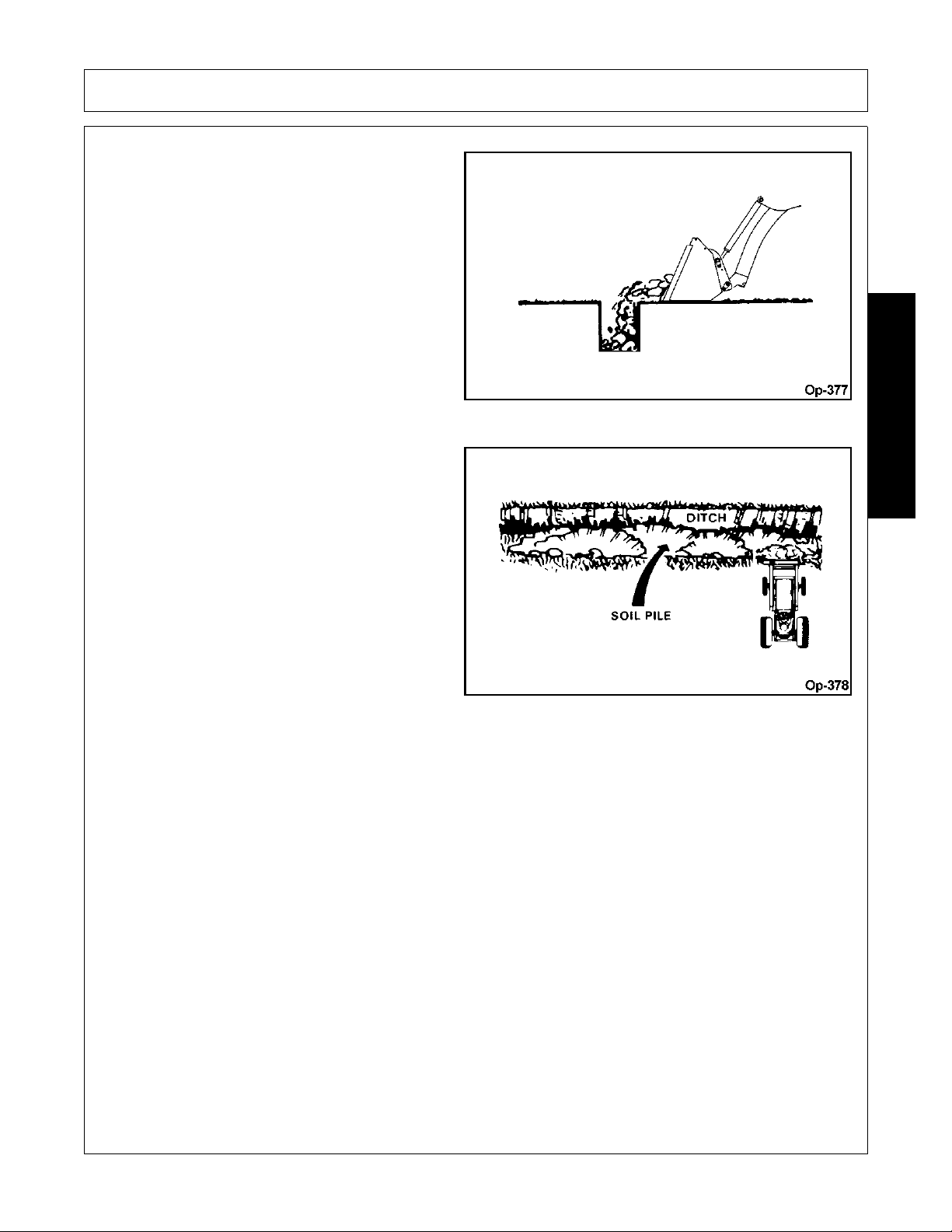
OPERATION
Leave dirt in bucket. Dumping on each pass wastes
time.
Operate tractor at right angles to ditch. Take as big
a bite as tractor can handle without lugging down.
OPERATION
1947/2047 01/11 Operation Section 4-35
© 2011 Alamo Group Inc.
Page 76
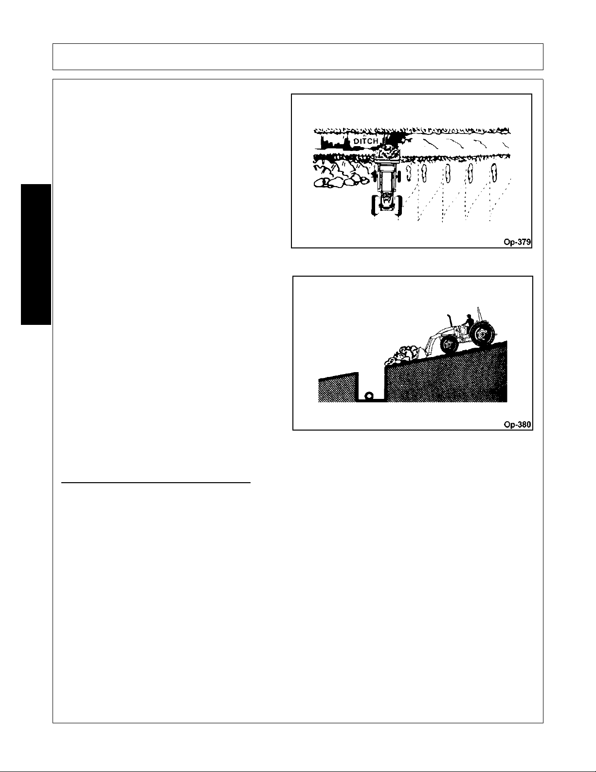
OPERATION
Leave dirt which drifts over side of bucket for final
cleanup.
Pile dirt on high side for easier backfilling on a
slope.
OPERATION
HANDLING LARGE HEAVY OBJECTS
1. Using front end loaders for handling large heavy object s such as large round or rectan gular bales, logs and
oil drums is not recommended.
2. Handling large heavy objects can be extremely dangerous due to:
• Danger of tractor rolling over.
• Danger of up-ending tractor.
• Danger of object rolling or sliding down loader arms onto operator.
3. If you must perform above work, protect yourself by:
• Never lifting load higher than necessary to clear ground when moving.
• Ballasting tractor rear to compensate for load.
• Never lifting large objects with equipment that does no t have an anti-rollback device.
• Moving slowly and carefully, avoiding rough terrain.
• Tilt bucket forward while lifting to maintain bucket angle.
1947/2047 01/11 Operation Section 4-36
© 2011 Alamo Group Inc.
Page 77
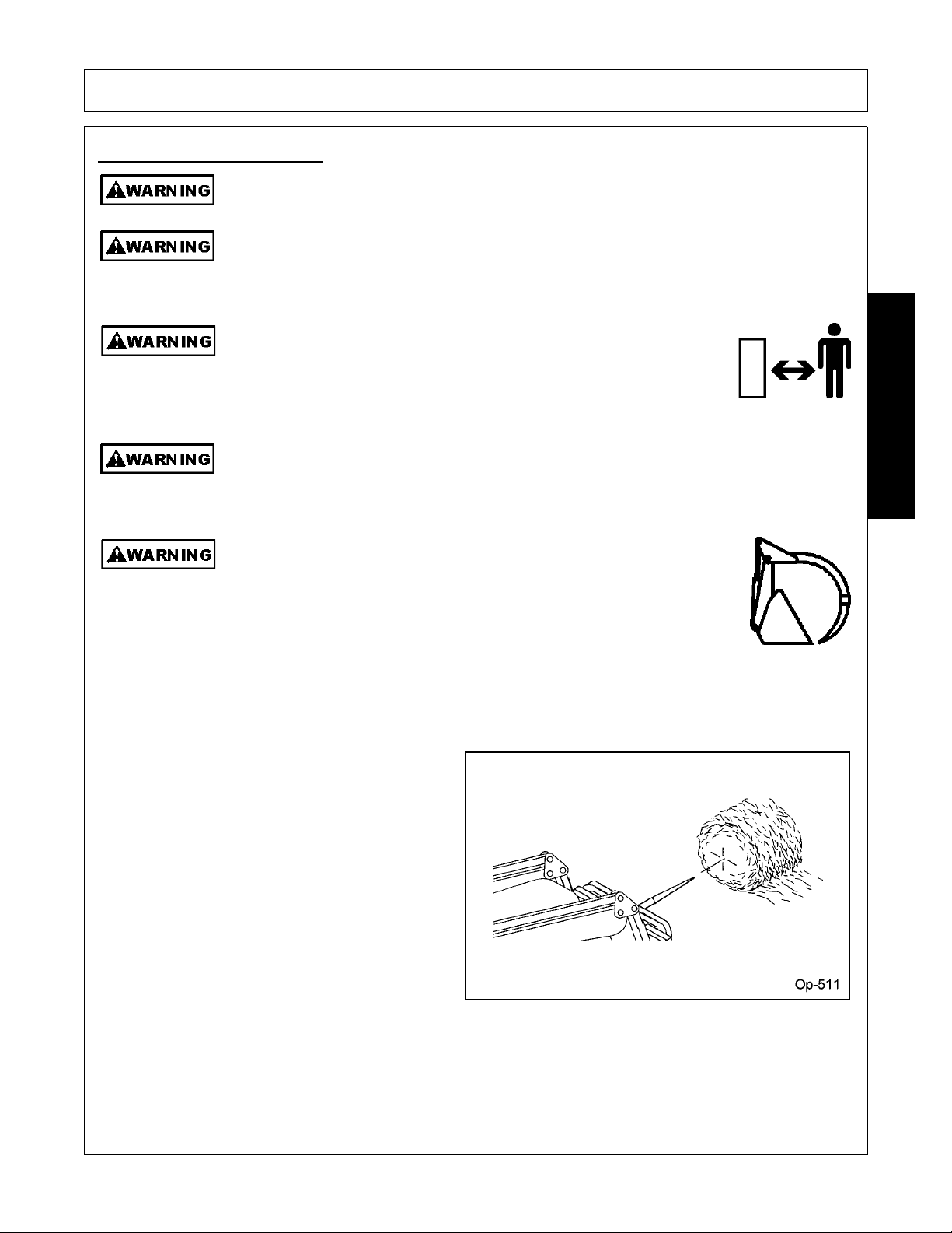
7.2 Operating Bale Spear
Keep bystanders 10 feet away from the tractor and loader while
operating. The bystanders could enter the path of the tractor or items
could fall from the loader resulting in serious injury to the bystander.
(SL-01)
Store the grapple bucket or bale spear attachment with the point(s) on the
ground. Walking into the point of the bale or grapple spear can cause
serious bodily injury. Never drive the bale spear or grapple bucket
attachment forward if a bystander is in front of the loader.
(SL-10)
Operate the bale spear using extreme caution. Sharp points on bale spear can cause
serious injury or death.
Because of size and weight of large bales, extreme ca re must be t aken in handling the m. Be
aware of forces acting on stacked bales due to gravity and keep worker s far from zones o f
potential hazard from shifting or falling bales. DO NOT ALLOW BYSTANDERS!
Keep bale spear and loader boom clear of overhead lines. Allowing loader boom or any
attachments to contact overhead power lines may electrify entire tractor and electrocute
(kill) operator.
OPERATION
OPERATION
Loader equipped with bale spear is designed to handle round bales up to 2000 pounds.
Load bale spear by approaching from round end to
prevent cutting strings or puncturing plastic or net
wrap.Tilt bale spear upward to prevent bale from
falling off of spear,
1947/2047 01/11 Operation Section 4-37
© 2011 Alamo Group Inc.
Page 78
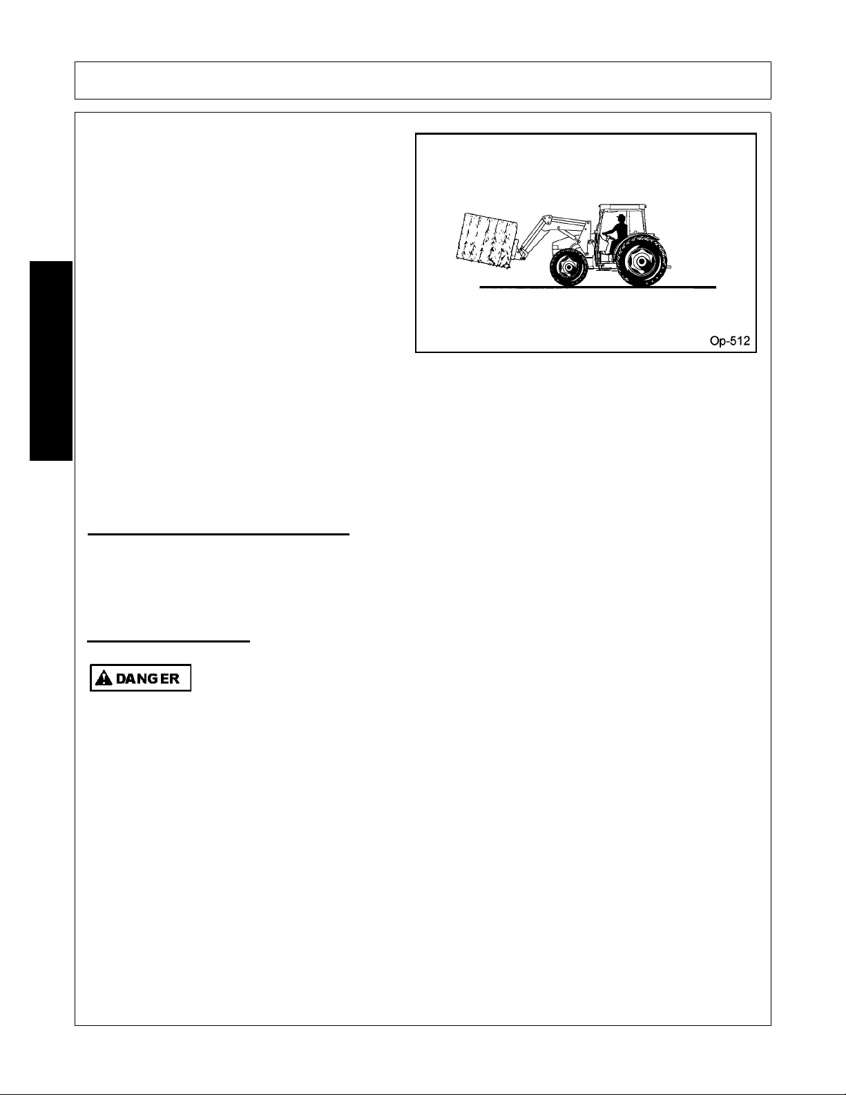
OPERATION
7.3 Shutting Down the Implement
Park the tractor on a level surface, place the transmission in park or neutral and apply the p arking brake, lower
the attached implement to the ground, shut down the engine, remove the key, and wait for all motion to come
to a complete stop before exiting the tractor. OPS-L- 0014
Never allow children to play on or around Tractor or Implement. Children can slip or fall off
the Equipment and be injured or killed. Inadvertent contact with controls can cause the
Implement to shift or fall crushing themselves or others.
(SG-25)
Carry bales as low to the ground as possible to
allow maximum visibility and avoid tipping.
OPERATION
8. Loader Storage
Properly preparing and storing the loader at the end of the season is critical to maintaining its appearance and
to help ensure years of dependable service. The following are suggeste d storage procedures:
• Thoroughly clean all debris off the loader to prevent damage from rotting grass and standing water.
• Lubricate all grease points det ailed in the maintenance section.
• Tighten all bolts and pins to the recommend torque.
• Check worn and damage parts. Perform repairs and make replacement s immediately so that the loader will
be ready for use at the start of the next season.
• Store the loader in a clean, dry place resting securely on parking stands at ground level.
• Use spray touch-up enamel where necessary to prevent rust and maintain the appearance of the loader.
1947/2047 01/11 Operation Section 4-38
© 2011 Alamo Group Inc.
Page 79
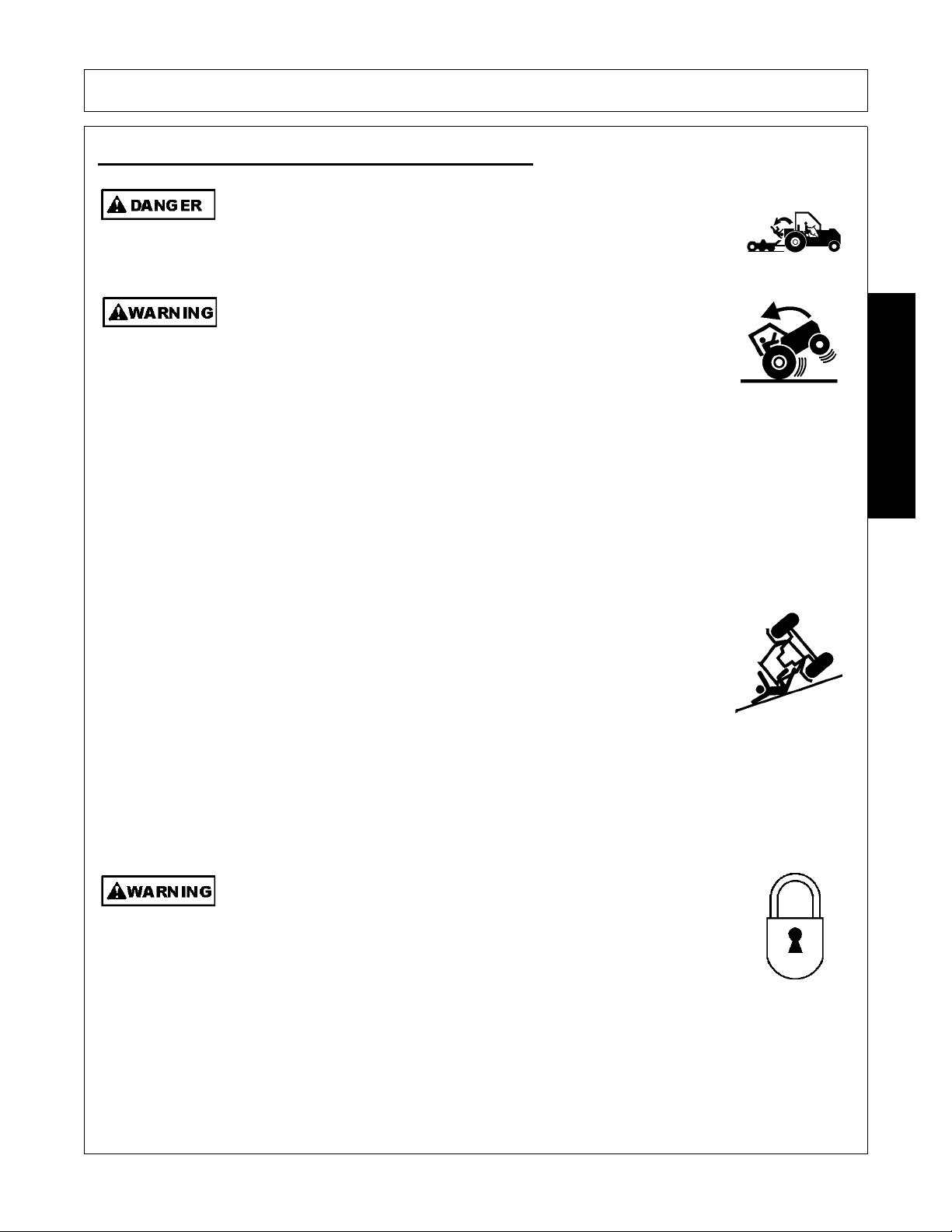
OPERATION
Never allow children or other persons to ride on the Tracto r or Implement.
Falling off can result in serious injury or death.
(SG-10)
Transport only at speeds where you can maintain control of the
equipment. Serious accidents and injuries can result from operating this
equipment at high speeds. Understand the Tractor and Implement and
how it handles before transporting on streets and highways. Make sure the Tractor steering
and brakes are in good condition and operate properly.
Before transporting the Tractor and Implement, determine the proper transport speeds for
you and the equipment. Make sure you abide by the following rules:
Test the tractor at a slow speed and increase the speed slowly. Apply the Brakes smoothly
to determine the stopping characteristics of the Tractor and Implement. As you increase
the speed of the Tractor the stopping distance increases. Determine the maximum
transport speed not to exceed 20 mph (30 kph) for transporting this equipment.
Test the equipment at a slow speed in turns. Increase the speed through the turn only after
you determine that the equipment can be operated at a higher speed. Use extreme care
and reduce your speed when turning sharply to prevent the tractor and implement from
turning over. Determine the maximum turning speed for you and this equipment before
operating on roads or uneven ground.
Only transport the Tractor and Implement at the speeds which allow you to properly control
the equipment.
Be aware of the operating conditions. Do not operate the Tractor with weak or faulty brakes
or worn tires. When operating down a hill or on wet or rain slick roads, the braking distance
increases: use extreme care and reduce you r speed. When operating in traffic always use
the Tractor’s flashing warning lights and red uce your speed. Be a ware of traf fic around yo u
and watch out for the other guy.
(SG-19)
Before transporting the tractor and Loader engage the loader valve travel
lock to prevent inadvertent contact with the joystick controller causing
sudden dropping of the loader and attachment. If the loader attachment,
such as a bucket, were to drop suddenly and hit the ground while
transporting, the tractor could stop immediately resulting in the operator
hitting the steering wheel or flying our of the operator’s seat. Serious injury
could result.
(SL-04)
9. Transporting the Tractor and Implement
OPERATION
1947/2047 01/11 Operation Section 4-39
© 2011 Alamo Group Inc.
Page 80
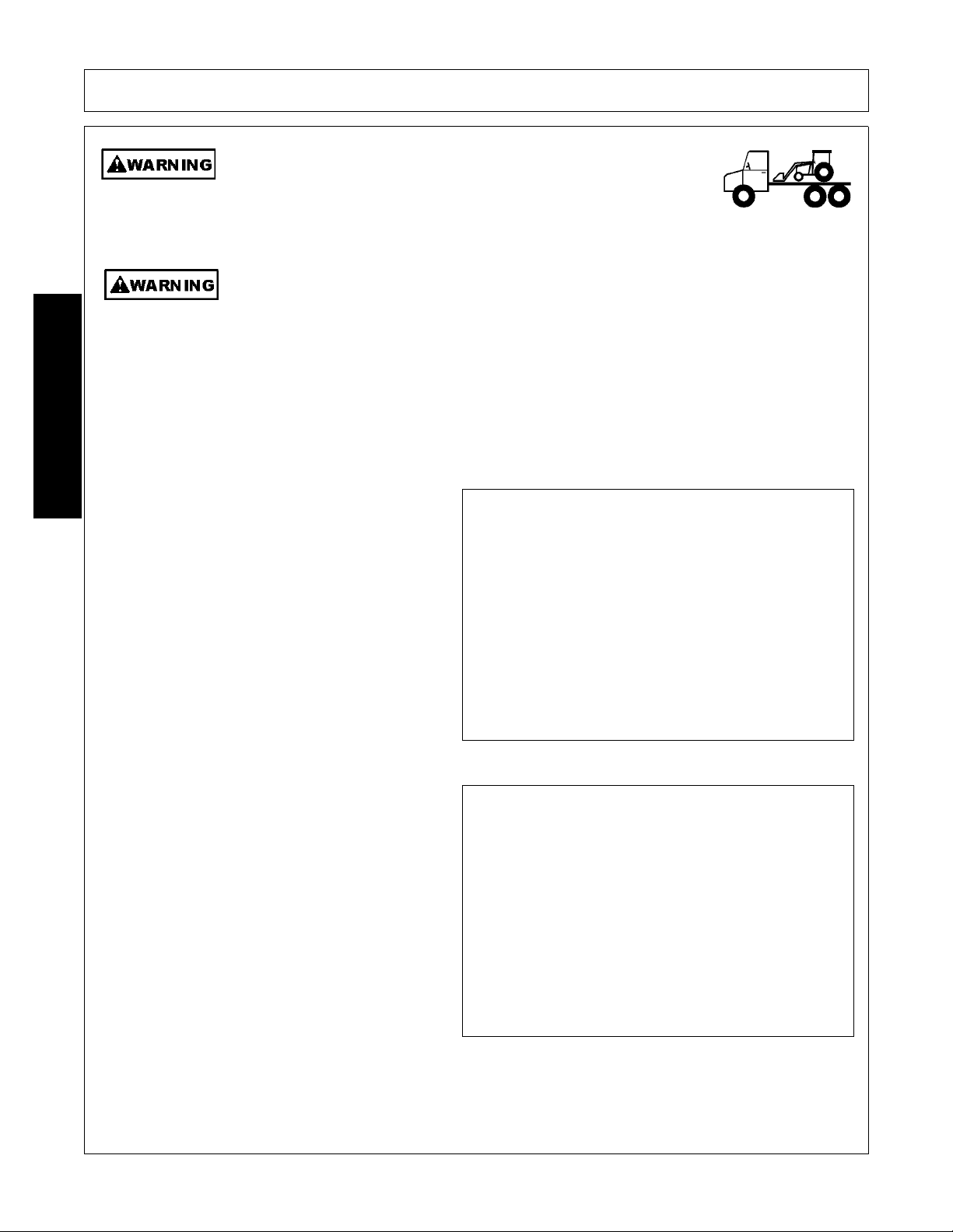
OPERATION
Lower the loader to the bed of the truck or trailer when transporting the
tractor and loader with a truck. Measure to ensure the transport height
does not exceed the legal limits. Contact with overhead obstructions or
power lines can cause property damage or serious injury.
(SL-34)
Before dismounting the tractor and loader, lower the loader to the ground or onto solid
support blocks. Sudden dropping of the loader and attachment could result in serious
injury.
(SL-38)
Inherent hazards of operating the tractor and implement and the possibility of accidents are not left behind
when you finish working in an area. Therefore, the operator mu st emp loy g ood judge men t and sa fe op eration
practices when transporting the tractor and implement between locations. By using good judgement and
following safe transport procedures, the possibility of accidents while moving between locations can be
substantially minimized. OPS-L- 0031
Before transporting the tractor and loader, idle the
tractor engine. When transporting, carry the loader
as low as possible maintaining adequate ground
clearance and visibility. Reduce tractor ground
speed when transporting a load. Take extra care
when traveling over rough terrain or on slopes.
OPS-L-0011
Before transporting the tractor on a public roadway
or boarding a trailer for transport, t he tractor brake
pedals should be locked together. Locking the
pedals ensures that both wheels brake
simultaneously while stopping, especially when
making an emergency stop.
Use extreme caution and avoid hard applications of
the tractor brakes when towing heavy loa ds at road
speeds. Never tow the implement at speeds
greater than 20 MPH (32 kph). OPS-U- 0018
OPERATION
Transporting on Public Roadways
1947/2047 01/11 Operation Section 4-40
© 2011 Alamo Group Inc.
Page 81

OPERATION
Make certain that the “Slow Moving Vehicle” (SMV) sign is installed in
such a way as to be cl early visible and legible. When transport ing the
Equipment use the Tractor flashing warning lights and follow all local
traffic regulations.
(SG-6)
Extreme caution should be used when transporting the tractor and impl ement on public roadways. The tractor
must be equipped with all req uired safety warning features including a SMV emble m and flashing warning
lights to alert drivers of the tractor’s presence. Remember that roadways are primarily designed for
automotive drivers and most drivers will not be looking out for you, therefore, you must look out for them.
Check your side view mirrors frequently and remember that vehicles will approach quickly because of the
tractor’s slower speed. Be extremely cautious when the piece of equipment that you are towing is wider than
the tractor tire width and/or extends beyond your lane of the road. OPS-L- 0032
The SMV (Slow-Moving Vehicle) emblem is
universal symbol used to alert drivers of the
presence of equipment traveling on roadways at a
slow speed. SMV signs are a triangular bright
orange with reflective red trim for both easy day
and night visibility. Make sure the SMV sign is
clean and visible from the rear of the unit before
transporting the tractor and implement on a public
roadway. Replace the SMV emblem if faded,
damaged, or no longer reflective. OPS-U- 0020
Make sure that all tractor flashing warning lights,
headlights, and brake/tail lights are functioning
properly before proceeding onto public roads. While
newer model tractors have plenty of lighting to
provide warning signals and operating lighting, most
older models are only equipped with operating lights.
Consult an authorized tractor dealer for lighting kits
and modifications available to upgrade the lighting on
older tractor models. OPS-U- 0021
OPERATION
1947/2047 01/11 Operation Section 4-41
© 2011 Alamo Group Inc.
Page 82

OPERATION
When operating on public roads, have consideration for other road users. Pull to the side of the road
occasionally to allow all following traffic to pass. Do not exceed the legal speed limit set in your country for
agricultural tractors. Always stay alert when transporting the tractor and implement on public roads. Use
caution and reduce speed if other vehicles or pedestrians are in the area. OPS-L- 0020
9.1 Hauling the Tractor and Implement
Before transporting a loaded tractor and implement,
measure the height and width dimensions and gross
weight of the complete loaded unit. Ensure that the
load will be in compliance with the legal limits set for
the areas that will be traveled through. OPS-U- 0024
Use adequately sized and rated trailers and
equipment to transport the tractor and implement.
Consult an authorized dealer to determine the proper
equipment required. Using adequately sized chains,
heavy duty straps, cables and/or binders, securely tie
down both the front and rear of the tractor utilizing the
proper tie down locations as specified by the tractor
manufacturer. OPS-U- 0025
OPERATION
1947/2047 01/11 Operation Section 4-42
© 2011 Alamo Group Inc.
Page 83

OPERATION
10. Troubleshooting Guide
TROUBLE POSSIBLE CAUSE POSSIBLE REMEDY
Loader slow or will not lift Hydraulic oil too heavy. Change to proper oil.
and/or dump
Oil filter plugged. Clean or replace filter.
Hydraulic pump worn. Repair or replace pump.
Oil line restricted or leaking. Check all hoses and tubes for leaks,
damage or restrictions. Replace
damaged or restricted hoses or tube
oil lines.
Control valve does not shift Inspect, clean, repair or replace
properly. valve.
Air in hydraulic system. Cycle lift cylinders and bucket
cylinders several times to free
system of air.
Cylinder leaks internally. Replace seals.
Faulty relief valve (tractor). Clean and replace relief valve.
OPERATION
Loader chatters or Air leak in pump inlet line. Check, tighten or replace inlet line.
vibrates when raising
or lowering.
Air in hydraulic system. Cycle lift and bucket cylinders.
Oil level too low. Add oil as required.
Faulty relief valve (tractor). Replace relief valve.
Oil Leaks Loose connections. Tighten fittings.
Defective fittings or hoses. Replace defective parts.
Worn or damaged o-ring Install a seal repair kit.
or wiper seal in cylinder See “Cylinder Service”.
rod end.
Worn or damaged o-rings Install an o-ring repair kit.
in valve.
1947/2047 01/11 Operation Section 4-43
© 2011 Alamo Group Inc.
Page 84

OPERATION
PROBLEM POSSIBLE CAUSE REMEDY
Insufficient lift capacity Load is greater than boom Check loader specifications.
lift capacity.
Improper hydraulic pump Repair or replace pump.
operation.
Internal lift cylinder leakage. Replace any worn parts and install
a seal repair kit. See “Cylinder
Service”.
Improper hydraulic valve Repair or replace valve.
operation.
Excessive wear on bucket Bucket is riding on cutting Use boom “FLOAT” position or
cutting edge edge instead of wear runners. bucket level indicator to ensure
OPERATION
bucket rides
Bucket cutting edge not Rear axle on tractor not level With tractor on level surface,
flat on theground. from side to side compare rear axle height from left to
right, measuring from axle center
toground. Adjust air pressure in rear
tires until axle height measures the
same for both sides.
1947/2047 01/11 Operation Section 4-44
© 2011 Alamo Group Inc.
Page 85

MAINTENANCE SECTION
© 2011 Alamo Group Inc.
Maintenance Section 5-1
Page 86
READ, UNDERSTAND, and FOLLOW the following Safety Messages. Serious injury or
death may occur unless care is taken to follow the warnings and instructions stated in the
Safety Messages. Always use good common sense to avoid hazards.
(SG-2)
Never interfere with factory-set hydraulic calibrations. Any change in calibration could
cause a failure of the equipment and may result in injury.
(SBH-13)
Always maintain the safety signs in good readable condition. If th e safety signs are missing,
damaged, or unreadable, obtain and install replacement safety signs immediately.
(SG-5)
Make certain that the “Slow Moving Vehicle” (SMV) sign is installed in
such a way as to be cl early visible and legible. When transport ing the
Equipment use the Tractor flashing warning lights and follow all local
traffic regulations.
(SG-6)
Do not modify or alter this Implement. Do not permit anyone to modify or alter this
Implement, any of its components or any Implement function.
(SG-8)
Never work under the Implement, the framework, or any lifted component
unless the Implement is securely supported or blocked up to prevent
sudden or inadvertent falling which could cause serious injury or even
death.
(SL-36)
Do not operate this Equipment with hydraulic oil or fuel leaking. Oil
and fuel are explosive and their presence could present a hazard. Do
not check for leaks with your hand! High-pressure oil streams from
breaks in the line could penetrate the skin and cause tissue damage
including gangrene. To check for a hose leak, SHUT the unit ENGINE
OFF and remove all hydraulic pressure. Wear oil imp ene trab le glo ves ,
safety glasses and use Cardboard to check for evidence of oil leaks. If
you suspect a leak, REMOVE the HOSE and have it tested at a Dealer.
If oil does penetrate the skin, have the injury treated immediately by a
physician knowledgeable and skilled in this procedure.
(SG-15)
Never attempt to lubricate, adjust, or remove material from the Implement while it is in
motion or while tractor engine is running.
(SG-20)
MAINTENANCE
MAINTENANCE
1947/2047 01/11 Maintenance Section 5-2
© 2011 Alamo Group Inc.
Page 87
MAINTENANCE
Do Not fill fuel tank while engine is running. Refuel only after engine has cooled down. If
fuel is spilled, move machine away from the area of the spill and avoid creating any source
of ignition until the fuel has evaporated.
(SBH-49)
Avoid contact with hot surfaces including hydraulic oil tanks, pumps, motors, valves and
hose connections. Relieve hydraulic pressure before performing maintenance or repairs.
Use gloves and eye protection when servicing hot components. Contact with a hot surface
or fluid can cause serious injury from burns or scalding.
(SG-34)
Use caution and wear protective gloves when handling sharp objects such as blades,
knives, and other cutting edges. Be alert to worn component surfaces which have sharp
edges. Sharp surfaces can inflict severe laceration injuries if proper hand protection is not
worn.
(SG-37)
Avoid contact with hot surfaces of the engine or muffler. Use gloves and eye protection
when servicing hot components. Contact with a hot surface or fluid can cause serious injury
from burns or scalding.
(SG-38)
Never allow anyone to get under the loader or attachment or to reach
through the loader lift arms when raised. Serious injury could result from
crushing or pinching by the loader or attachment.
(SL-06)
PARTS INFORMATION
Bush Hog products are designed utilizing specifically matched system components to ensure optimum
equipment performance. These parts are made and tested to Bush Hog specifications. Non-genuine "will fit"
parts do not consistently meet these specifications. The use of “will fit” parts may reduce equipment
performance, void warranties, and present a safety hazard. Use genuine Bush Hog parts for economy and
safety.
(SPBH-2)
SEE YOUR BUSH HOG DEALER
MAINTENANCE
NEVER perform maintenance beneath a raised loader unless loader is properly supported
to prevent accidental lowering.
1947/2047 01/11 Maintenance Section 5-3
© 2011 Alamo Group Inc.
Page 88
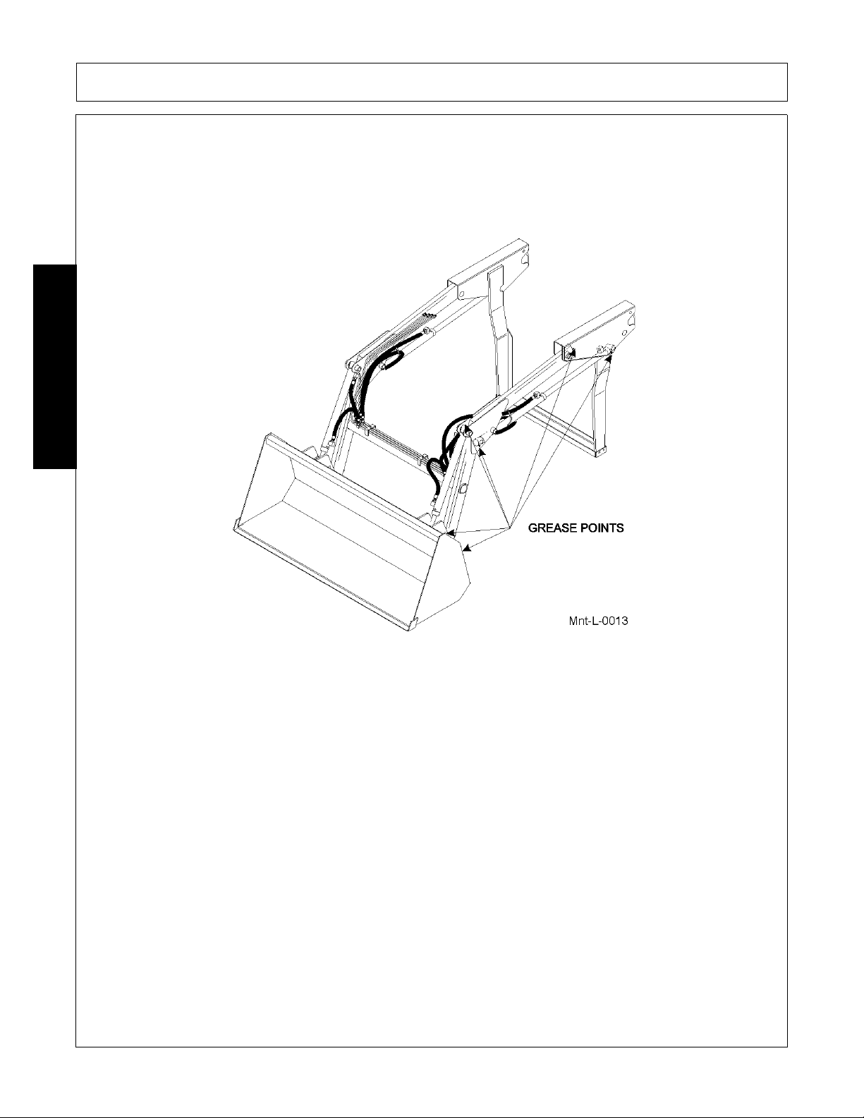
MAINTENANCE
Lubrication Schedule
Before operating your Loader, take the time to inspect and rep air an y damag e to the machine or tractor. Only a
minimum of time and effort is required to regularly maintain this machine to provide long life and trouble free
operation.
MAINTENANCE
Lubricate all grease fittings: one at each end of lift boom arms and one at rod and base ends of each lift and
bucket cylinders.
NOTE: Fully retract bucket to a comfortable height to grease bucket/loader boom joint. Do not reach or stand
under a raised loader or attachment without proper support.
1947/2047 01/11 Maintenance Section 5-4
© 2011 Alamo Group Inc.
Page 89
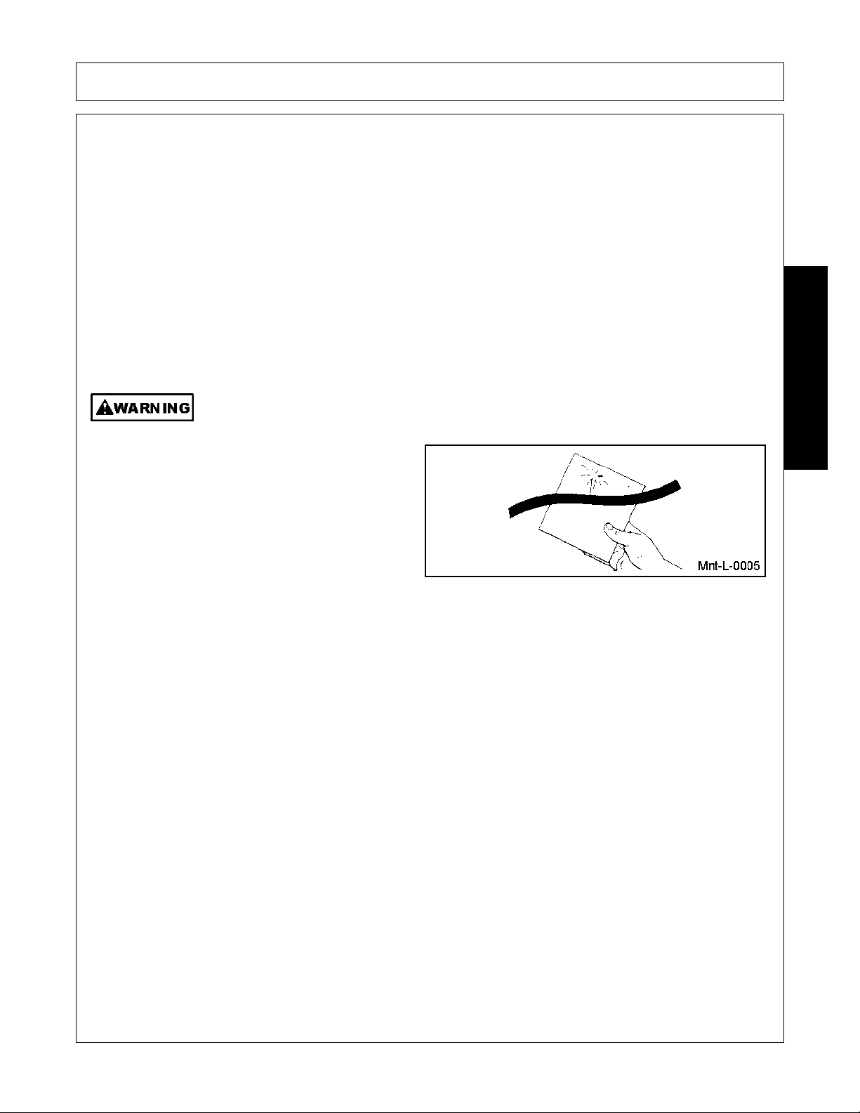
MAINTENANCE
Daily Maintenance
Regular maintenance of your loader and hydraulic system will insure maximum loader efficiency and long life.
1. Check fluid level of tractor hydraulic system before starting each day’s operation. If necessary, add
hydraulic oil as recommended in your tractor operator’s manual.
2. After every eight hours of operation, lubricate all twelve grease fittings; one at each end of lift boom arms
and one at rod and base ends of each lift and bucket cylinder.
3. After every ten hours of operation, check all hardware and tighten where required.
4. Replace hoses immediately if they are damaged by a cut or scrape, extruded at the fittings or leaking.
Hydraulic oil leaks should be repaired promptly to avoid loss of oil and serious personal injury from
escaping oil.
Escaping hydraulic fluid under pressure can penetrate skin, causing serious personal injury.
• DO NOT use your hand to ch eck f or le aks. Use
a piece of wood or cardboard and wear eye
protection to search for leaks.
• Stop engine and relieve pressure before
connecting or disconnecting lines.
• Tighten all connections before starting engine
or pressurizing lines.
MAINTENANCE
NOTE: If any fluid is injected into skin, obtain medical attention immediately or gangrene may result.
1947/2047 01/11 Maintenance Section 5-5
© 2011 Alamo Group Inc.
Page 90
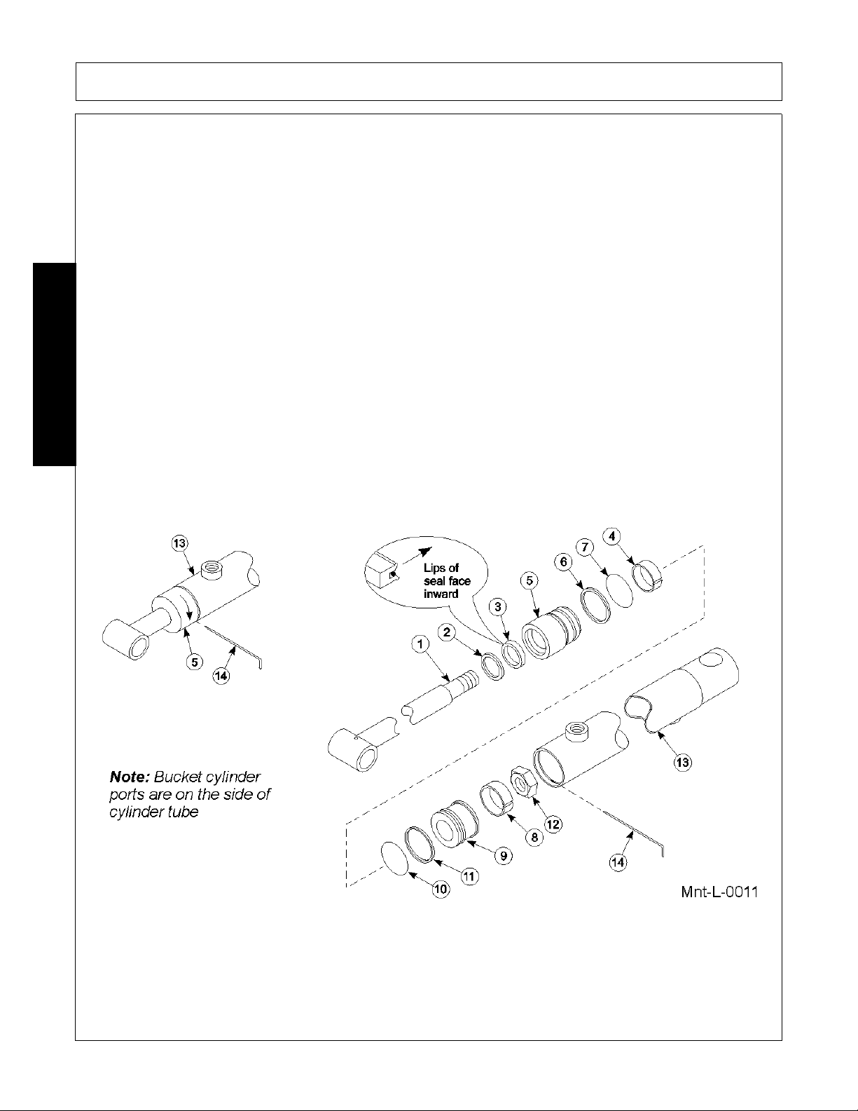
MAINTENANCE
Hydraulic Pressure Check
Following procedure outlines hydraulic pressure check.
1. Obtain a pressure gauge that measures 3000 PSI in 50 PSI increments.
2. Install gauge into the hydraulic line connecting the lo ader valve and to the base port bucket cylinders.
3. Start engine and adjust to 1700-2200 RPM.
4. Push bucket control lever to pressurize the hydraulic line with the gauge att ached. Hold the control until the
cylinders reach the fully extended position. Holding the control with cylinders fully extended will give you
the hydraulic system pressure on the gauge.
5. If pressure is not correct, refer to “TROUBLESHOOTING GUIDE” in the Operation Section for possible
remedy, or contact your dealer.
Cylinder Service
Loader cylinders are designed to be reliable and easy to service. If a cylinder should malfunction during
warranty period, return complete cylinder assembly, without disassembling, to your authorized service
department or contact your authorized service department for instructions. Unauthorized disassembly of a
MAINTENANCE
cylinder in warranty period will VOID WARRANTY.
1947/2047 01/11 Maintenance Section 5-6
© 2011 Alamo Group Inc.
Page 91

MAINTENANCE
Lift and Bucket Cylinder Dissemble
Following is an outline procedure for disassembling and reassembling cylinders
1. Hold cylinder tube (13) stationary and pull wire ring (14) out through slot.
2. Pull shaft (1), with all assembled parts, out of cylinder tube (13).
Note: Resistance will be felt until piston seal (8) slides over wire retaining ring groove.
3. Remove elastic locknut (12) from end of shaft and slide cylinder piston (9) and cylinder head (5) off shaft.
4. Remove piston wear ring (8), piston seal (11), and o-ring (10) from outside grooves on piston(9).
5. Remove wiper seal (2), rod seal (3) and wear ring (4) from inside of cylinder head (4) and o-ring (7) with
backup washer (6) from groove on outside of head.
6. Clean all parts including cylinder tube, in a suitable cleaning solvent, then use air pre ssure to blow any dirt
or excess solvent from all parts.
7. Examine all parts for wear or damage and replace, if necessary.
Lift and Bucket Cylinder Reassembly
Note: Be careful not to damage seals and o-rings on edges or holes in cylinder tube. Inspe ct and remove b urrs
and sharp edges if necessary before reassembly.
1. Place rod seal (3) into groove inside cylinder head.
Note: Lips of seal (3) must be face inward and seal must be firmly seated in groove.
2. Install wiper seal (2) with lip of seal facing out and flush with top of cylinder head (5). Install wear ring (4)
inside other end of head (5).
3. Place o-ring (7) with back-up washer (6) in gro ove on outside of head. Back-up washer must be on rod
side.
4. Remove sharp edges on outer edge of the threaded end of shaft (1). Lubricate wiper seal (2) and rod seal
(3) in head and carefully slide head onto shaft.
5. Place o-ring (10), piston seal (11) and piston wear ring (8) in grooves on outside of piston (9).
MAINTENANCE
Note: For easier installation, place piston seal (11) in 120°F water to warm seal.
6. Slide piston (9) onto threaded end of shaft and install lock nut (12). Tighten lock nut to 100 lbs.
7. Lubricate piston wear ring (8) and p iston sea l (11) on piston, o-ring (7) and backup washer ( 6) o n hea d an d
inside of cylinder tube (13), then carefully slide piston and head into cylinder tube (13).
8. Insert wire retaining ring (14) into slot in cylinder tube (13). Apply pressure to wire ring to thread it into
groove while turning cylinder head.
1947/2047 01/11 Maintenance Section 5-7
© 2011 Alamo Group Inc.
Page 92
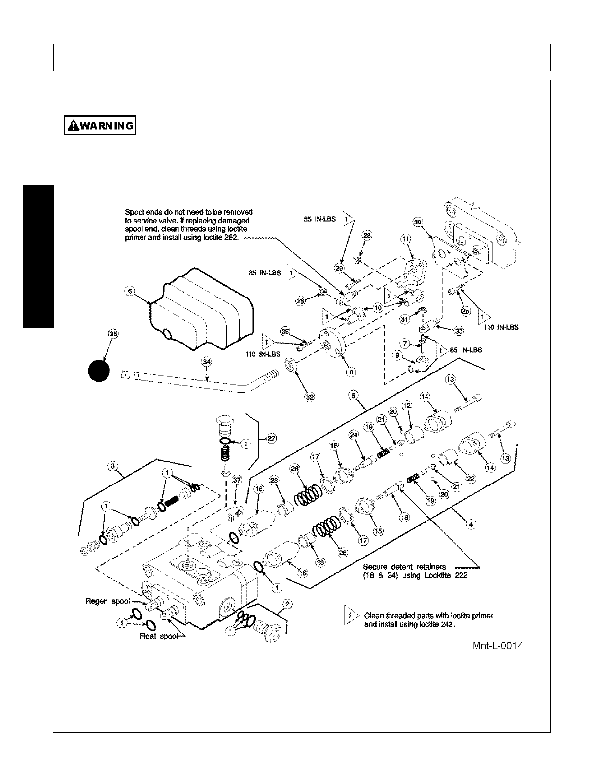
Prince LVR Valve Service
The valve has a valve relief setting pre-set at the factory. Tampering with this setting can
cause serious injury to operator and damage to tr actor or loader. Unauthorized adjustments
or service to valve relief will VOID WARRANTY of both loader and tractor. If adjustments or
service to valve relief are required during warranty period, an a uthorized service dep artment
must be consulted for authorization.
MAINTENANCE
MAINTENANCE
1947/2047 01/11 Maintenance Section 5-8
© 2011 Alamo Group Inc.
Page 93

MAINTENANCE
Valve Disassembly
Note: It is advisable to mark or tag all parts so they will be reinstalled in their proper position.
1. Slide boot (6) to top of handle (34). Remove hex head cap screws (36) from rod ends (9 & 10). Remove
handle with boot and adapter plate (8). Remove nuts (28) from spool stud (7) and rod end assemblies (10)
from valve.
Note: Spool adapters (33) are factory assembled. Removal from spools is not necessary. If replacing a
damaged adapter, clean threads with loctite primer and install using loctite 262.
2. Remove hex head cap screws ( 13) and deten t end cap s (14) from b oth spools. Re move detent sl eeve (12)
from regen spool. Remove steel balls (20), poppet (21) and poppet spring (19) from detent retainer (24).
Remove retaining flat (15) and detent spacer (1 6) from regen spool.
3. Secure handle end of regen spool. Using a rod through retainer ball holes, remove detent retainer (24)
from regen spool.
Note: Detent re tainers (18 & 24) ar e installed on spools using Locktite 222 or equivalent. If spool adapter
comes loose instead of detent retainer, pull spool completely out of valve and secure spool using vice grips
on land section of spool not machined for valve bore.
4. Remove washer (17), centering spring (26) and stop cup (23) from regen spool.
5. Holding in on float detent sleeve (22), push in on float spool from handle end and remove steel balls (20)
from float detent retainer (18). Remove float detent sleeve (22), poppet (21), poppet spring (19), retaining
flat (15) and spacer (16) from float spool.
6. Secure handle end of float spool. Using a rod through retainer ball holes, remove detent retainer (18) from
float spool.
MAINTENANCE
Note: Detent re tainers (18 & 24) ar e installed on spools using Locktite 222 or equivalent. If spool adapter
comes loose instead of detent retainer, pull spool completely out of valve and secure spool using vice grips
on land section of spool not machined for valve bore.
7. Remove washer (17), centering spring (26) and stop cup (23) from float spool.
8. Push spools in from handle end until rear spool seals (1) are exposed. Using wire hook and screwdriver,
remove rear spool seals. Push spools in from the rear until front spool seals (1) are exposed. Using wire
hook and screwdriver, remove front spool seals.
9. Clean all parts, including valve body, in suitable cleaning solvent. After cleaning parts with solvent, use air
pressure to blow any dirt or excess solvent from all parts including inside of valve body.
1947/2047 01/11 Maintenance Section 5-9
© 2011 Alamo Group Inc.
Page 94
MAINTENANCE
Never crawl under or allow children to play around or on a loader that is disconnected from
the tractor. The loader could fall crushing a person resulting in serious injury or death.
(SL-13)
Do not remove the attachment from the loader when the loader is disconnected from the
tractor. The attachment stabilizes the loader. If the attachment is removed, the loader will
fall and could result in serious injury.
(SL-26)
Only disconnect and store the loader on firm flat ground. Make sure the loader stands are
properly installed and rest on firm ground or support blocks. If the stands sink or fail, the
loader could fall causing serious injury.
(SL-27)
Valve Reassembly
1. Examine all parts for wear and damage and replace if necessary.
2. Lubricate all o-rings and spools with oil to prevent damage when assembling.
3. Lubricate all detent and spring centering parts with a light coat of grease before assembling.
4. Reassemble all parts in reverse order of disassembly.
Note: Use Locktite 222 or equivalent when installing detent retainers (18 & 24).
Relief Valve, Load Check Plugs and Power Beyond Sleeve
Note: Relief valve (3), load check plugs (40) and power bey ond sleeve (2) may be removed separa tely to clean
inspect or replace parts without removing valve spools.
Note: If repairing or replacing relief valve (3), torque larger hex nut (relief body) to 20-25 ft./lbs.
Replacing Handle Parts
If replacing damaged handle parts, cleans threads with loctite primer and install using loctite 242. Torque parts
as shown in Illustration.
MAINTENANCE
Storage
NOTE: When loader hydraulics are disconnected from tractor, the tractor hydraulic circuit must be completed.
Failure to do so will result in tractor hydraulic pump damage.
1947/2047 01/11 Maintenance Section 5-10
© 2011 Alamo Group Inc.
Page 95
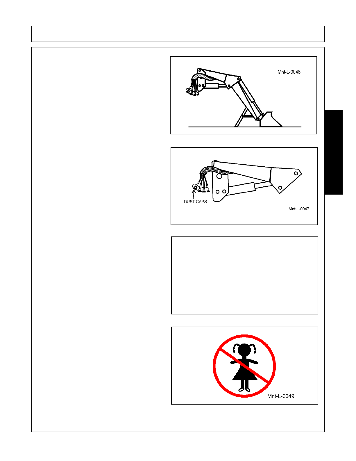
MAINTENANCE
1. Store loader with attachment securely
attached.
2. Place dust caps on hydraulic quick couplers.
MAINTENANCE
3. Do not remove attachment from stored load er.
4. Do not allow children to play on or around
loader.
1947/2047 01/11 Maintenance Section 5-11
© 2011 Alamo Group Inc.
Page 96
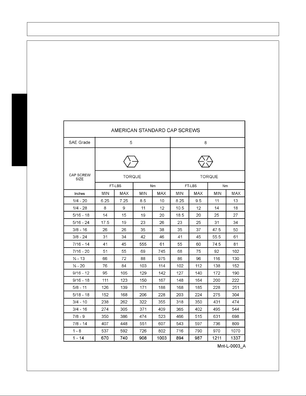
MAINTENANCE
Proper Torque for Fasteners
The chart lists the correct tightening torque for fasteners. When bolts are to be tightened or replaced, refer to
this chart to determine the grade of bolts and the proper torque except when specific torque values are
assigned in manual text.
RECOMMENDED TORQUE IN FOOT POUNDS UNLESS OTHERWISE STATED IN THE MANUAL*
NOTE: These values apply to fasteners as received from supplier, dry or when lubricated with normal engine
oil. They do not apply if special g raphited or moly disulphide grea ses or other ex treme pressur e lubricants are
used. This applies to both UNF fine and UNC coarse threads.
MAINTENANCE
1947/2047 01/11 Maintenance Section 5-12
© 2011 Alamo Group Inc.
Page 97
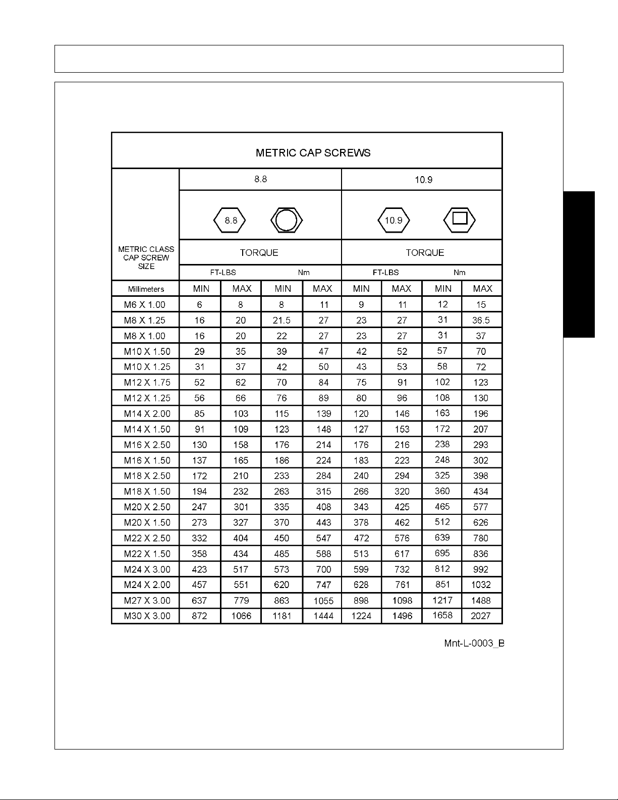
MAINTENANCE
MAINTENANCE
1947/2047 01/11 Maintenance Section 5-13
© 2011 Alamo Group Inc.
Page 98
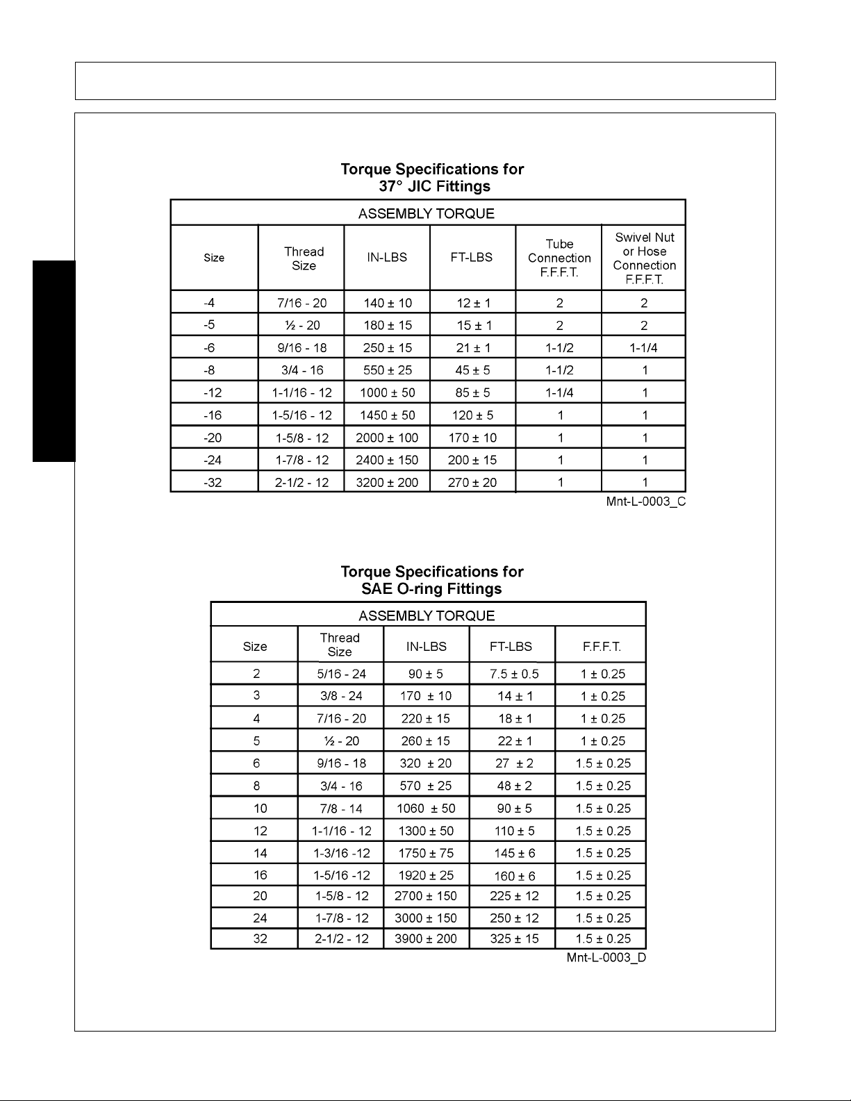
MAINTENANCE
MAINTENANCE
1947/2047 01/11 Maintenance Section 5-14
© 2011 Alamo Group Inc.
Page 99

Page 100

LIMITED WARRANTY
Bush Hog warrants to the original purchaser of any new Bush Hog equipment, purchased from an author ized Bush
Hog dealer, that the equipment be free from defects in material and workmanship for a period of one (1) year for
non-commercial, state and municipalities’ use an d ninety (90) days fo r commercial use from date of retail sale . The
obligation of Bush Hog to the purchaser under this warranty is limited to the repair or replacement of defective
parts.
Replacement or repair parts installed in the equipment covered by this limited warranty are warranted fo r ninety
(90) days from the date of purchase of such part or to the expiration of the applicable new equipment warranty
period, whichever occurs later. Warranted p arts shall be provided at no cost to the user at an authorized Bush Hog
dealer during regular working hours. Bush Hog reserves the right to inspect any equipment or parts which are
claimed to have been defective in material or workmanship.
DISCLAIMER OF IMPLIED WARRANTIES & CONSEQUENTIAL DAMAGES
Bush Hog’s obligation under this limited warranty, to the extent allowed by law, is in lieu of all warranties, implied or
expressed, INCLUDING IMPLIED WARRANTIES OF MERCHANTABILITY AND FITNESS FOR A PARTICULAR
PURPOSE and any liability for incidental and consequential damages with respect to the sale or use of the items
warranted. Such incidental and consequential damages shall include but not be limited to: transportation charges
other than normal freight charges; cost of installation other than cost approved by Bush Hog; duty; taxes; charges
for normal service or adjustment; loss of crops or any other loss of income; rental of substitute equipment,
expenses due to loss, damage, detention or delay in the delivery of equipment or parts resulting from acts beyond
the control of Bush Hog.
THIS LIMITED WARRANTY SHALL NOT APPLY:
1. To vendor items which carry their own warranties, such as engines, tires, and tubes.
2. If the unit has been subjected to misapplication, abuse, misuse, negligence, fire or other accident.
3. If parts not made or supplied by Bush Hog have b een used in connectio n with the unit, if, in the sole judgement
of Bush Hog such use affects its performance, stability or reliability.
4. If the unit has been altered or rep air ed out sid e of an au thorized Bush Hog dealer ship in a m anner which, in th e
sole judgement of Bush Hog, affects its performance, stability or reliability.
5. To normal maintenance service and normal replacement items such as gearbox lubricant, hydraulic fluid, worn
blades, or to normal deterioration of such things as belts and exterior finish due to use or exposure.
6. To expendable or wear items such as teeth, chains, sprockets, belts, springs and any other items that in the
company’s sole judgement is a wear item.
NO EMPLOYEE OR REPRESENTATIVE OF BUSH HOG IS AUTHORIZED TO CHANGE THIS LIMITED
WARRANTY IN ANY WAY OR GRANT ANY OTHER WARRANTY UNLESS SUCH CHANGE IS MADE IN
WRITING AND SIGNED BY BUSH HOG’S SERVICE MANAGER, 2501 GRIFFIN AVE., SELMA, ALABAMA
36703.
Record the model number, serial number and date
purchased. This information will be helpful to your
dealer if parts or service are required.
MODEL NUMBER ___________________________
MAKE CERTAIN THE WARRANTY
HAS BEEN FILED WITH BUSH HOG
SELMA, ALABAMA
SERIAL NUMBER ___________________________
DATE OF RETAIL SALE ______________________
 Loading...