

Page 1
1747
FRONT END
LOADER
Published 05/11 MATERIAL HANDLING PARTS MANUAL
PARTS MANUAL
SECTION 1-28
Page 2

PA RTS ORDERING GUIDE
The following instructions are offered to help eliminate needless delay and error in processing purchase orders for the equipment in this section.
1. The Parts Section is prepared in logical sequence and grouping of parts that belong
to the basic machine featured in this manual. Part Numbers and Descriptions are given
to help locate the parts and quantities required.
2. The Purchase Order must include the name and address of the person or organization ordering the parts, who should be charged, and if possible, the serial number of the
machine for which the parts are ordered.
3. The Purchase Order must clearly list the quantity of each part, the complete and correct
part number (be sure to include all periods), and the basic name of the part.
4. The Manufacturer reserves the right to substitute parts where applicable.
5. Some parts are unlisted items which are special production items not normally stocked
and are subject to special handling. Request a quotation for such parts before sending
a Purchase Order.
6. The Manufacturer reserves the right to change prices without prior notice.
For maximum safety and to guarantee optimum product reliability, always
use genuine BUSH HOG Parts. The use of inferior replacement parts may
causepremature or catastrophic failure which could result in serious injury
or death.Direct any questions regarding parts to:
BUSH HOG
2501 Griffin Ave.
Selma, AL 36703
www.bushhog.com
Contact Us
800-304-2836
©2009 Alamo Group Inc.
Page 3
Page 4

LIMITED WARRANTY
Bush Hog warrants to the original purchaser of any new Bush Hog equipment, purchased from an authorized Bush
Hog dealer, that the equipment be free from defects in material and workmanship for a period of one (1) year for
non-commercial, state and municipalities’ use and ninety (90) days for commercialuse from date of retail sale. The
obligation of Bush Hog to the purchaser under this warranty is limited to the repair or replacement of defective
parts.
Replacement or repair parts installed in the equipment covered by this limited warranty are warranted for ninety
(90) days from the date of purchase of such part or to the expiration of the applicable new equipment warranty
period, whichever occurs later. Warranted parts shall be provided at no cost to the user at an authorized Bush Hog
dealer during regular working hours. Bush Hog reserves the right to inspect any equipment or parts which are
claimed to have been defective in material or workmanship.
DISCLAIMER OF IMPLIED WARRANTIES & CONSEQUENTIAL DAMAGES
Bush Hog’s obligation under this limited warranty, to the extent allowed by law, is in lieu of all warranties, implied or
expressed, INCLUDING IMPLIED WARRANTIES OF MERCHANTABILITY AND FITNESS FOR A PARTICULAR
PURPOSE and any liability for incidental and consequential damages with respect to the sale or use of the items
warranted. Such incidental and consequential damages shall include but not be limited to: transportation charges
other than normal freight charges; cost of installation other than cost approved by Bush Hog; duty; taxes; charges
for normal service or adjustment; loss of crops or any other loss of income; rental of substitute equipment,
expenses due to loss, damage, detention or delay in the delivery of equipment or parts resulting from acts beyond
the control of Bush Hog.
THIS LIMITED WARRANTY SHALL NOT APPLY:
1. To vendor items which carry their own warranties, such as engines, tires, and tubes.
2. If the unit has been subjected to misapplication, abuse, misuse, negligence, fire or other accident.
3. If parts not made or supplied by Bush Hog have been used in connection with the unit, if, in the sole judgement
of Bush Hog such use affects its performance, stability or reliability.
4. If the unit has been altered or repaired outside of an authorized Bush Hog dealership in a manner which, in the
sole judgement of Bush Hog, affects its performance, stability or reliability.
5. To normal maintenance service and normal replacement items such as gearbox lubricant, hydraulic fluid, worn
blades, or to normal deterioration of such things as belts and exterior finish due to use or exposure.
6. To expendable or wear items such as teeth, chains, sprockets, belts, springs and any other items that in the
company’s sole judgement is a wear item.
NO EMPLOYEE OR REPRESENTATIVE OF BUSH HOG IS AUTHORIZED TO CHANGE THIS LIMITED
WARRANTY IN ANY WAY OR GRANT ANY OTHER WARRANTY UNLESS SUCH CHANGE IS MADE IN
WRITING AND SIGNED BY BUSH HOG’S SERVICE MANAGER, 2501 GRIFFIN AVE., SELMA, ALABAMA
36703.
Record the model number, serial number and date
purchased. This information will be helpful to your
dealer if parts or service are required.
MODEL NUMBER ________________________________
SERIAL NUMBER ________________________________
DATE OF RETAIL SALE ___________________________
MAKE CERTAIN THE WARRANTY
HAS BEEN FILED WITH BUSH HOG
SELMA, ALABAMA
Page 5

BUSH HOG / MATERIAL HANDLING REPAIR PARTS MANUAL
TABLE OF CONTENT
1747 FRONT END LOADER
ITEM PAGE
FRAMES
Mainframe and Subframe ...................................................1-28A-1
MOUNTING KITS
Mounting Kit 2-6772Kubota Models - BX 1800, BX 1830, BX 2200,BX 2300 FWA,
COMPATABLE WITH RCK54-22BX AND RCK60B-22BX MID MOUNT MOWERS ......1-28B-1
Mounting Kit 2-7325 Kubota Models - BX 1500FWA, COMPATABLE WITH RCK54-15BX
Mid Mount Mowers ........................................................1-28B-2
MAY, 2011
Mounting Kit 2-7407 Massey Freguson Models - GC2300 FWA..........................................1-28B-3
Mounting Kit 2-7442 Case IH Models DX18E, DX22E, DX24E AND DX25EFWA
New Holland Models - TZ18DA, TZ22DA, TZ24DA, TZ25DA FWA, T1010,
Boomer1020 FWA.................................................................................................................1-28B-4
ATTACHMENTS
Bucket...................................................................................................................................1-28C-1
HYDRAULICS
Hydraulic System (Basic Loader)..........................................................................................1-28D-1
Hydraulic Valve (Dukes)........................................................................................................1-28D-2
Hydraulic Cylinder (Lift).........................................................................................................1-28D-3
Hydraulic Cylinder (Bucket) ..................................................................................................1-28D-4
Control ValveAnd Plumbing Kit 2-7553 Kubota Models - BX1500, BX1800,
Bx1830, Bx2200, Bx2230.......................................................................................1-28E-1, 1-28E-2
Control ValveAnd Plumbing Kit 2-7408
Massey Ferguson Models - GC2300.......................................................1-28E-3, 1-28E-4, 1-28E-5
Control ValveAnd Plumbing Kit 2-7443
Case IH Models DX18E, DX22E, DX24E AND DX25EFWA
New Holland Models - TZ18DA, TZ22DA, TZ24DA, TZ25DA FWA, T1010,
Boomer1020 FWA..................................................................................................1-28E-6, 1-28E-7
DECALS
Decals (Placement)...............................................................................................................1-28F-1
Decals (Pictorials) .................................................................................................................1-28F-2
Page 6

NOTES:
Page 7
BUSH HOG / MATERIAL HANDLING REPAIR PARTS MANUAL
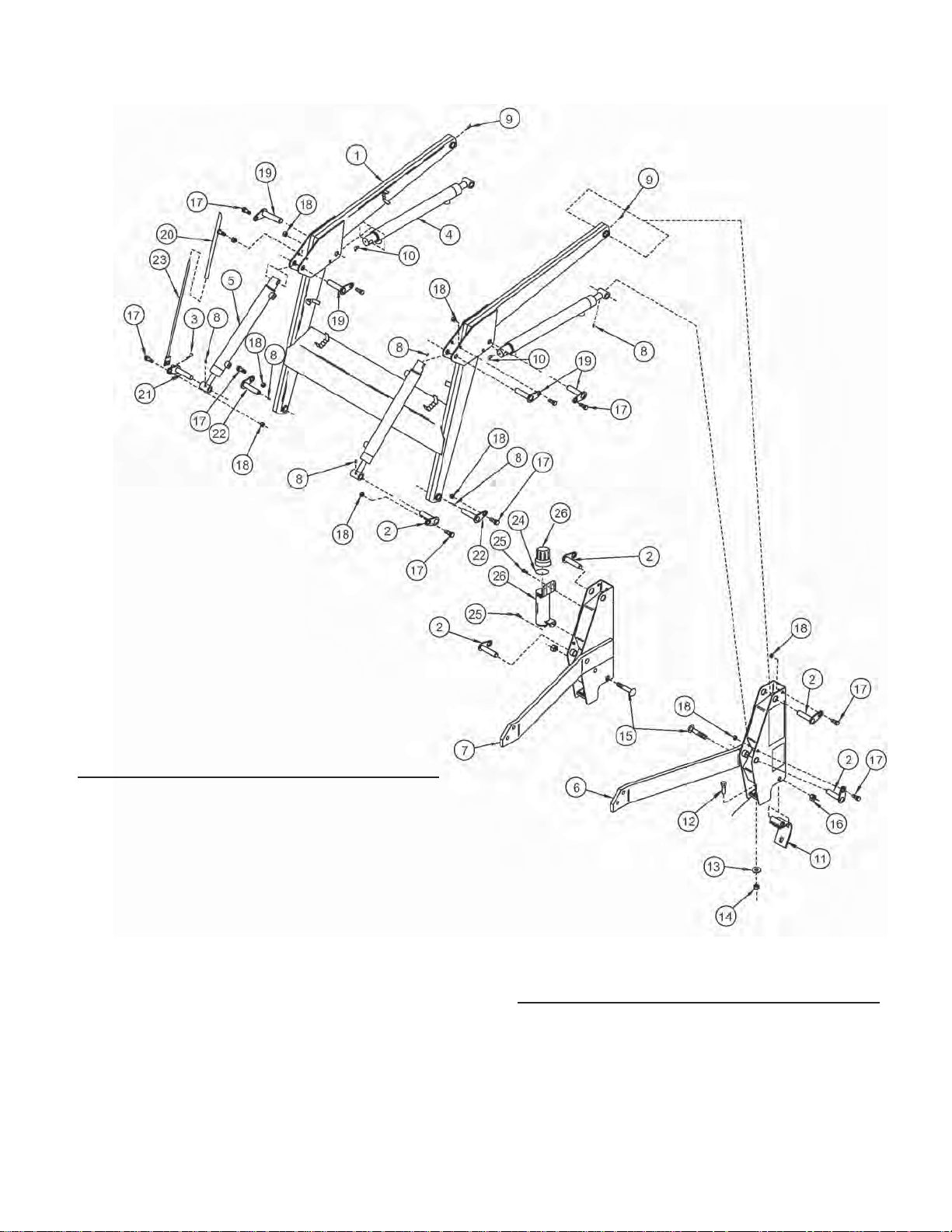
1747 MAINFRAME AND SUBFRAME
MAY, 2011
REF. PART DESCRIPTION QTY.
NO. NO. REQ’D.
1 46001+ Boom Assembly 1
2 32820-1 Pin Assembly 5
3 00026200 Pin, Cotter, 1.50 1
4 45302 Cylinder, Lift 1
5 45303 Cylinder, Bucket 2
6 48751 Side Frame, Left
7 48748 Side Frame, Right 1
8 6075-4 Fitting, Grease, 1/4-28, Straight 8
9 6075-6 Fitting, Grease, 1/4-28, 45° 2
10 6075-7 Fitting, Grease, 1/4-28, 90° 2
11 45587 Hinge Assembly 2
12 ------- Screw, Cap, 1/2 X 1-3/4 2
13 00002700 Washer, Flat, 1/2 2
14 ------- Nut, Lock, 1/2-13 2
15 ------- Carriage Bolt, 5/8-11 X 3-1/2 2
16 ------- Nut, Lock, 5/8-11 2
17 31353 Bolt, Shoulder, 3/8-16 X 1 12
18 ------- Nut, Lock, 3/8-16 12
19 32820-2 Pin Assembly 4
REF. PART DESCRIPTION QTY.
NO. NO. REQ’D.
20 25210 Guide Tube 1
21 32823+ Pin Assembly 1
22 36118 Pin Assembly 2
23 32825+ Rod Assembly 1
24 00776964 Seal, Manual Canister 1
25 ------- Screw, Self Tapping, .25 X .75 2
26 00776031 Canister With Cap, Includes Item 31 1
1-28A-1
Page 8

Page 9
BUSH HOG / MATERIAL HANDLING REPAIR PARTS MANUAL
MAY, 2011
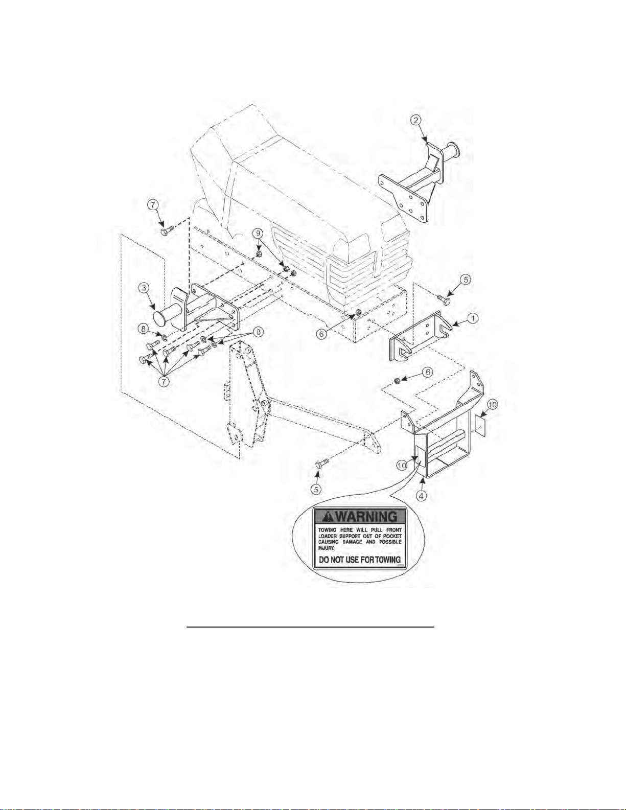
MOUNTING KIT 2-6772
Kubota Models - BX 1800, BX 1830, BX 2200,BX 2300 FWA, COMPATABLE WITH RCK54-22BX
AND RCK60B-22BX MID MOUNT MOWERS
REF. PART DESCRIPTION QTY.
NO. NO. REQ’D.
1 48739 Front Mounting Bracket 1
2 48736-1 Mounting Bracket, Left 1
3 48736-2 Mounting Bracket, Right 1
4 49197 Yoke Assy. w/Safety Decal 1
5 ------- Capscrew 1/2”-13 x 1-1/2” 8
6 ------- Locknut 1/2” -13 8
7 ------- Capscrew 9/16”-18 x 1-1/2” 12
8 ------- Lockwasher 9/16” 6
9 ------- Locknut 9/16” -18 6
10 39240 Warning Decal 2
1-28B-1
Page 10

BUSH HOG / MATERIAL HANDLING REPAIR PARTS MANUAL
MOUNTING KIT 2-7325
Kubota Models - BX 1500FWA, COMPATABLE WITH RCK54-15BX MID MOUNT MOWERS
MAY, 2011
REF. PART DESCRIPTION QTY.
NO. NO. REQ’D.
1 51601 Front Mounting Bracket 1
2 51595-1 Mounting Bracket, Left 1
3 51595-2 Mounting Bracket, Right 1
4 49197 Yoke Assy. w/Safety Decal 1
5 ------- Capscrew 1/2”-13 x 1-1/2” 8
6 ------- Locknut 1/2” -13 8
7 ------ Capscrew 9/16”-18 x 1-1/2” 12
8 ------- Lockwasher 9/16” 6
9 ------- Locknut 9/16” -18 6
10 39240 Warning Decal 2
1-28B-2
Page 11

BUSH HOG / MATERIAL HANDLING REPAIR PARTS MANUAL
MOUNTING KIT 2-7407
Massey Freguson Models - GC2300 FWA
MAY, 2011
REF. PART DESCRIPTION QTY.
NO. NO. REQ’D.
1 52173 Front Mounting Bracket 1
2 52180 Mounting Bracket, Left 1
3 52182 Mounting Bracket, Right 1
4 52501 Yoke Assy. w/Safety Decal 1
5 -------- Capscrew 1/2”-13 x 1-1/2” 8
6 ------- Locknut 1/2” -13 8
7 ------- Capscrew M12-1.75 x 40 12
8 ------- Lockwasher 1/2” 6
9 39240 Warning Decal 2
1-28B-3
Page 12

BUSH HOG / MATERIAL HANDLING REPAIR PARTS MANUAL
MOUNTING KIT 2-7442
Case IH Models DX18E, DX22E, DX24E AND DX25EFWA
NEW HOLLAND MODELS - TZ18DA, TZ22DA, TZ24DA, TZ25DA FWA, T1010,
BOOMER1020 FWA
MAY, 2011
REF. PART DESCRIPTION QTY.
NO. NO. REQ’D.
1 52507 Front Mounting Bracket 1
2 52518 Mounting Bracket, Left 1
3 52519 Mounting Bracket, Right 1
4 52513 Yoke Assy. w/Safety Decal 1
5 39240 Warning Decal 2
6 ------- Capscrew 5/8”-11 X 1-1/2” 3
7 ------- Capscrew 1/2”-13 x 1-1/2” 16
8 ------- Locknut 5/8”-11 3
9 -------- Locknut 1/2”-13 16
1-28B-4
Page 13

BUSH HOG / MATERIAL HANDLING REPAIR PARTS MANUAL
BUCKET ASSEMBLY
MAY, 2011
REF. PART DESCRIPTION QTY.
NO. NO. REQ’D.
1 36070 Bucket Assembly 48” 1
2 36068 Side Cutting Edge 2
3 22541-2 Bottom Cutting Edge 1
1-28C-1
Page 14

Page 15

BUSH HOG / MATERIAL HANDLING REPAIR PARTS MANUAL
HYDRAULIC SYSTEM
MAY, 2011
REF. PART DESCRIPTION QTY.
NO. NO. REQ’D.
1 46132 Tube, Oil Line (BCR) 1
2 46133 Tube, Oil Line (BCB) 1
3 46130 Tube, Oil Line (LCB) 1
4 46131 Tube, Oil Line (LCR) 1
5 63149100 Fitting, Elbow, 9/16 X 9/16 8
6 32837-1 Hose, .250 X 10.50 2
7 32837-15 Hose, .250 X 34.00 2
8 32837-3 Hose, .250 X 20.00 2
9 32837-7 Hose, .250 X 15.00 2
1-28D-1
Page 16

BUSH HOG / MATERIAL HANDLING REPAIR PARTS MANUAL
HYDRAULIC VALVE
MAY, 2011
REF. PART DESCRIPTION QTY.
NO. NO. REQ’D.
52190 Control Valve Assy. (Dukes) 1
1 41270+ Repair Kit, Seal - Pilot Operated Relief 1
2 36583 Repair Kit, Pilot Operated Relief 1
3 33101+ Repair Kit, Load Check 2
4 41269+ Repair Kit, Spring Centering 1
5 33103+ Repair Kit, Detent Spring Centering 1
6 25944+ Plate, 1-Way Restrictor W/.109 Hole 1
7 36584 Power Beyond Kit 1
1-28D-2
Page 17

BUSH HOG / MATERIAL HANDLING REPAIR PARTS MANUAL
HYDRAULIC CYLINDER - LIFT
MAY, 2011
REF. PART DESCRIPTION QTY.
NO. NO. REQ’D.
45302 Cylinder Assy. (Lift) 1
1 45434 Shaft, Cylinder 1
2 45313 Head, Cylinder 1
3 45311 Piston 1
4 ------- Locknut 3/4”-10 1
5 45436 Tube, Cylinder 1
6 45318 Seal Repair Kit 1
7 ------- Seal, Wiper 1
8 ------- Seal, U-Cup 1
9 ------- Wear Ring 1
10 ------- Washer, Backup 1
11 ------- “O” Ring 1
12 ------- Wear Ring 1
13 ------- “O” Ring 1
14 ------- Seal, Piston 1
15 ------- Wire, Retaining 1
1-28D-3
Page 18

BUSH HOG / MATERIAL HANDLING REPAIR PARTS MANUAL
HYDRAULIC CYLINDER - BUCKET
MAY, 2011
REF. PART DESCRIPTION QTY.
NO. NO. REQ’D.
45303 Bucket Cylinder Assembly 1
1 45430 Shaft, Cylinder 1
2 45313 Head, Cylinder 1
3 45311 Piston 1
4 ------- Locknut 3/4”-10 1
5 45428 Tube, Cylinder 1
6 45318 Seal Repair Kit 1
7 ------- Seal, Wiper 1
8 ------- Seal, U-Cup 1
9 ------- Wear Ring 1
10 ------- Washer, Backup 1
11 ------- “O” Ring 1
12 ------- Wear Ring 1
13 ------- “O” Ring 1
14 ------- Seal, Piston 1
15 ------- Wire, Retaining 1
1-28D-4
Page 19

BUSH HOG / MATERIAL HANDLING REPAIR PARTS MANUAL
CONTROL VALVE AND PLUMBING KIT 2-7553
Kubota Models - BX1500, BX1800, BX1830, BX2200, BX2230
MAY, 2011
REF. PART DESCRIPTION QTY.
NO. NO. REQ’D.
1 51908 Valve, (1600psi) 1
2 38902 Ball 1
3 43635 Boot 1
4 38902 Handle 1
5 ------- Screw, Socket Head, 1/4-28 X 3/4" 3
6 38904-1 Stud, Ball Joint 1
7 38900-5 Ball Joint, Female 1
8 ------- Nut, Lock, 1/4-28 1
9 ------- Washer, Lock, 1/4" 2
10 ------- Nut, Hex, 1/4-28 2
11 26009-3 Ball Joint, Male 2
12 38903 Bracket, Valve Linkage 1
13 ------- Screw, Socket Head, 5/16-24 X 3/4" 1
14 38911-1 Screw, Flat Head Socket, 5/16-24 X 3/4" 1
15 32844-1 Fitting, Straight, 9/16 Jic X 9/16 O-Ring 4
16 42062-6 Fitting, Straight, Swivel, 9/16 Jic X 9/16 O-Ring 2
17 34128-3 Fitting, Elbow, 90°, 9/16 Jic X 9/16 Jic 2
18 31213-5 Fitting, Elbow, 45°, 9/16 Jic X 9/16 O-Ring 2
REF. PART DESCRIPTION QTY.
NO. NO. REQ’D.
19 44277-2 Fitting, Elbow, 90°, 9/16 Jic X 9/16 O-Ring 2
20 32845-1 Fitting, Elbow, 90°, 9/16 Jic X 9/16 O-Ring 1
21 6147-9 Coupler, Female 4
22 36240-1 Band, Spiral, 3/4", Blue 1
23 36240-2 Band, Spiral, 3/4", Red 1
24 36240-3 Band, Spiral, 3/4", Yellow 1
25 36240-4 Band, Spiral, 3/4", Green 1
26 51850 Valve Stand Assembly 1
27 51910 Cover Assembly, W/Decals 1
28 44274-1 Plug, Square Tube 1
29 6067-1 Nut, Speed, 5/16-18 2
30 ------- Screw, Cap, 5/16-18 X 3/4" 2
31 ------- Washer, Lock, 5/16 2
32 ------- Screw, Cap, 1/4-20 X 2" 2
33 ------- Nut, Lock, 1/4-20 2
34 25801 Decal, Warning 1
35 38929 Decal, Single Handle Control 1
1-28E-1
Page 20

BUSH HOG / MATERIAL HANDLING REPAIR PARTS MANUAL
CONTROL VALVE AND PLUMBING KIT 2-7553
Kubota Models - BX1500, BX1800, BX1830, BX2200, BX2230
MAY, 2011
REF. PART DESCRIPTION QTY.
NO. NO. REQ’D.
1 51908 Valve, Assembly 1
2 51858 Block, Adapter, Bx1500, Bx1800, Bx2200 1
53346 Block, Adapter, Bx1830, Bx2230 1
3 51857 Clamp, Hose 2
4 ------- Washer, Lock, 5/16" 2
5 ------- Screw, Cap, 1/4-20 X 1-1/4" 2
6 ------- Nut, Lock, 1/4-20 2
7 ------- Washer, Flat, 1/4" 2
8 ------- Screw, Cap, 9/16-18 X 2-1/4" 2
9 ------- Washer, Lock, 9/16" 2
10 ------- Screw, Cap, 8mm-1.25 X 40mm 2
11 31213-5 Fitting, Elbow, 45°, 9/16 Jic X 9/16 O-Ring 1
12 2845-1 Fitting, Elbow, 90°, 9/16 Jic X 9/16 O-Ring 2
REF. PART DESCRIPTION QTY.
NO. NO. REQ’D.
13 6000-20 O-Ring, 5/8" 2
14 6137-9 Coupler, Male Adapter 4
15 36240-1 Band, Spiral, 3/4", Blue 1
16 36240-2 Band, Spiral, 3/4", Red 1
17 36240-3 Band, Spiral, 3/4", Yellow 1
18 36240-4 Band, Spiral, 3/4", Green 1
19 36388-8 Hose, 3/8 X 38” 4
20 36386-10 Hose, 3/8 X 90” (Pressure & Tank) 2
21 36386-3 Hose, 3/8 X 94” (Power Beyond) 1
22 34853-71 Sleeve, 1.66 X 90” 2
23 34853-72 Sleeve, 1.66 X 94” 1
24 34853-33 Sleeve, 1.66 X 38” 4
1-28E-2
Page 21

BUSH HOG / MATERIAL HANDLING REPAIR PARTS MANUAL
CONTROL VALVE AND PLUMBING KIT 2-7408
Massey Ferguson Models - GC2300
MAY, 2011
REF. PART DESCRIPTION QTY.
NO. NO. REQ’D.
1 53462 Valve Assy. 1
2 52183 Adapter Block 1
3 ------- Capscrew 1/2-13 x 2.00” Lg Gr5 2
4 ------- Lock Nut 1/2-13 2
5 ------- Capscrew 6mm-1.00 x 45 2
6 ------- Lockwasher 1/4 2
7 6000-20 O-Ring 2
8 -------- Hhcs 3/8-16 X 1.25” Lg 1
9 ------- Lock Nut Ydp 3/8-16 1
10 8222-3 Clamp, Tube 5/8 Zp 1
11 39047-2 Hose Clamp, Double 0.687 1
12 32845-1 Adp Hyd Elbow 6mj - 6mb90 1
13 32844-1 Adapter, 9/16-18 37 1
REF. PART DESCRIPTION QTY.
NO. NO. REQ’D.
14 36249-1 Fitting - Straight W/ O-Ring 1
15 38226-1 Elbow 6 MJIC - 6 FJIC x 45 1
16 36240-5 Spiral Band, Plastic-Blue 1
17 36240-6 Spiral Band-Plast-Red 1
18 36240-7 Spiral Band-Plast-Yellow 1
19 36240-8 Spiral Band-Plast-Green 1
20 6137-9 Coupling,Male 1/4” 4
21 36388-8 Hose 3/8 X 38” (Loader Boom Oil Lines) 4
22 32837-18 Hose 0.25 X 72” (Pressure, Tank, 3
And Power Beyond)
23 34853-78 Nylon Sleeve, 1.00 X 72” 3
24 34853-33 Nylon Sleeve 1 X 38” 4
25 8137-1 Strap-Adjust .19 X 11.00 B 1 4
1-28E-3
Page 22

BUSH HOG / MATERIAL HANDLING REPAIR PARTS MANUAL
CONTROL VALVE AND PLUMBING KIT 2-7408
Massey Ferguson Models - GC2300
MAY, 2011
REF. PART DESCRIPTION QTY.
NO. NO. REQ’D.
1 53462 Assy, Loader Valve - 1800 Psi 1
2 56064 Tube,Valve Mount 1
3 56065 Plate,Valve Mount 1
4 56066 Plate,Valve Cover 1
5 48670-3 Adapter,Str 8 mab - 6 mb 4
6 32844-5 Adaptor, 9/16-18x3/4-16 2
7 32845-7 Adp Hyd Elbow 6mj - 8mb90 1
8 48004 Orifice Plate 1
9 47879 Orifice Plate 1
10 6147-9 Coupling Body 4
11 36240-5 Spiral Band,Plastic-Blue 1
REF. PART DESCRIPTION QTY.
NO. NO. REQ’D.
12 36240-6 Spiral Band-Plast-Red 1
13 36240-7 Spiral Band-Plast-Yellow 1
14 36240-8 Spiral Band-Plast-Green 1
15 ------- Capscreqw 3/8-16 x2.25” Lg Gr 5 2
16 ------- Flatwashert 3/8 W-Std 2
17 ------- Capscrew, 5/16-18 X .75” Lg Gr 5 6
18 ------- Lockwasher 5/16 6
19 44274-1 Plug, Square Tube 1
20 38929 Decal-Single Handle Control 1
21 25801 Decal-Warning 1
22 41840-3 Locknut 3/8-16 2
1-28E-4
Page 23

BUSH HOG / MATERIAL HANDLING REPAIR PARTS MANUAL
CONTROL VALVE AND PLUMBING KIT 2-7408
Massey Ferguson Models - GC2300
MAY, 2011
REF. PART DESCRIPTION QTY.
NO. NO. REQ’D.
55827 Kit, Sub-Assy, Includes Items 1-11 1
1 ------- Clevis, Spool Lock 1
2 ------- Plate, Adapter 1
3 55821 Stud, Spool 1
4 55822 End, Rod 1
5 ------- Screw, Cap 3
6 55823 Assy, Rod End 2
7 ------- Nut, Hex 3
8 ------- Screw, Cap 2
9 ------- Screw, Cap 1
10 ------- Washer, Flat 1
11 55824 Kit, Spool Lock Hardware 1
12 56004 Kit, Bent Handle 1
13 55826 Kit, Boot/Cable Tie 1
14 55917 Adapter, Float Spool 1
15 55918 Adapter, Regen Spool 1
1-28E-5
Page 24

BUSH HOG / MATERIAL HANDLING REPAIR PARTS MANUAL
CONTROL VALVE AND PLUMBING KIT 2-7443
Case IH Models DX18E, DX22E, DX24E AND DX25EFWA
NEW HOLLAND MODELS - TZ18DA, TZ22DA, TZ24DA, TZ25DA FWA, T1010,
BOOMER1020 FWA
MAY, 2011
REF. PART DESCRIPTION QTY.
NO. NO. REQ’D.
1 52190 Valve, Assembly, 1
2 ------- Capscrew, 1/2-13 X 2-3/4" 2
3 ------- Flatwasher, 1/2" 2
4 ------- Locknut, 1/2-13 2
5 43518-2 Fitting, Straight, 1/4 Bspt Male X 9/16 Jic Male 3
6 34128-3 Fitting, Elbow, 90°, 9/16 Jic F Swivel X 2
9/16 Jic M
7 36240-1 Band, Spiral, 3/4", Blue 1
8 36240-2 Band, Spiral, 3/4", Red 1
9 36240-3 Band, Spiral, 3/4", Yellow 1
REF. PART DESCRIPTION QTY.
NO. NO. REQ’D.
10 36240-4 Band, Spiral, 3/4”, Green 1
11 6137-9 Coupler, Quick, Male 4
12 36388-8 Hose, 3/8 X 38" (Loader Boom Oil Lines) 4
13 36386-18 Hose, 3/8 X 82” (Pressure & Power Beyond) 2
14 36386-6 Hose, 3/8 X 72" (Tank) 1
15 34853-44 Sleeve, Hose, 82" 2
16 34853-78 Sleeve, Hose, 72” 1
17 34853-33 Sleeve, Hose, 38” 4
18 8137-1 Strap, Adjustable 14
19 52788 Poppet, Assembly With O-Ring 1
1-28E-6
Page 25

BUSH HOG / MATERIAL HANDLING REPAIR PARTS MANUAL
CONTROL VALVE AND PLUMBING KIT 2-7443
Case IH Models DX18E, DX22E, DX24E AND DX25EFWA
NEW HOLLAND MODELS - TZ18DA, TZ22DA, TZ24DA, TZ25DA FWA, T1010,
BOOMER1020 FWA
MAY, 2011
REF. PART DESCRIPTION QTY.
NO. NO. REQ’D.
1 52190 Valve, (1800 Psi) 1
2 38902 Ball 1
3 43635 Boot 1
4 38908 Handle 1
5 ------- Screw, Socket Head, 1/4-28 X 3/4" 3
6 38904-1 Stud, Ball Joint 1
7 38900-5 Ball Joint, Female 1
8 ------- Locknut, 1/4-28 1
9 ------- Lockwasher 1/4" 2
10 ------- Hex Nut 1/4 - 28 2
11 26009-3 Ball Joint, Male 2
12 38903 Bracket, Valve Linkage 1
13 ------- Screw, Socket Head, 5/16-24 X 3/4" 1
14 ------- Screw, Flat Head Socket, 5/16-24 X 3/4" 1
15 32844-1 Fitting, Straight, 9/16 Jic X 9/16 O-Ring 4
16 42062-6 Fitting, Straight, Swivel, 9/16 Jic X 9/16 O-Ring 2
17 34128-3 Fitting, Elbow, 90°, 9/16 Jic X 9/16 Jic 2
18 31213-5 Fitting, Elbow, 45°, 9/16 Jic X 9/16 O-Ring 2
19 44277-2 Fitting, Elbow, 90°, 9/16 Jic X 9/16 O-Ring 2
20 32845-1 Fitting, Elbow, 90°, 9/16 Jic X 9/16 O-Ring 1
21 6147-9 Coupler, Female 4
22 36240-1 Band, Spiral, 3/4", Blue 1
23 36240-2 Band, Spiral, 3/4", Red 1
24 36240-3 Band, Spiral, 3/4", Yellow 1
REF. PART DESCRIPTION QTY.
NO. NO. REQ’D.
25 36240-4 Band, Spiral, 3/4", Green 1
26 50206 Valve Stand, Tube 1
27 51910 Cover Assembly, Valve, With Decals 1
28 44274-1 Plug, Square Tube 1
29 6067-1 Nut, Speed, 5/16-18 2
30 ------- Capscrew 5/16-18 X 3/4" 2
31 ------- Lockwasher 5/16 2
32 ------- Capscrew 1/4 - 20 X 2" 2
33 ------- Locknut 1/4 - 20 2
34 52529 Angle, Valve Mounting 1
35 ------- Capscrew, 3/8-16 X 2-1/4" 2
36 ------- Locknut, 3/8-16 2
37 25801 Decal, Warning 1
38 38929 Decal, Single Handle Control 1
39 48004 Restrictor Plate .109 Orfice 1
40 25944+ Restrictor Plate .062 1
1-28E-7
Page 26

Page 27

BUSH HOG / MATERIAL HANDLING REPAIR PARTS MANUAL
MAY, 2011
DECALS
REF. PART DESCRIPTION QTY.
NO. NO. REQ’D.
1 50057411 Logo Decal Bush Hog 1
2 50069066 Model 1747 2
3 52740 Warning Oil Leaks 2
4 52203 Warning Lock Valve In Transport 1
5 52204 Instruction Loader Positions 1
6 D469 Warning Loader Safety 1
7 D468 Danger Crushing, Electrocution, Falling Hazard 2
8 D471 Warning Handling Bales 1
9 D470 Danger Use Rops, Seatbelt, Rear Ballast 1
10 03200347 Reflector SMV Sign 1
11 00776031 Canister, Operator’s Manual 1
12 50069198 Operators Manual (1747 Loader) 1
1-28F-1
Page 28

BUSH HOG / MATERIAL HANDLING REPAIR PARTS MANUAL
MAY, 2011
DECALS
1
2
4
3
5
6
7
REF. PART DESCRIPTION QTY.
NO. NO. REQ’D.
8
9
1 50057411 Logo Decal Bush Hog 1
2 50069066 Model 1747 2
3 52740 Warning Oil Leaks 2
4 52203 Warning Lock Valve In Transport 1
5 52204 Instruction Loader Positions 1
6 D469 Warning Loader Safety 1
7 D468 Danger Crushing, Electrocution, Falling Hazard 2
8 D471 Warning Handling Bales 1
9 D470 Danger Use Rops, Seatbelt, Rear Ballast 1
1-28F-2
Page 29

Page 30

2501 Griffin Ave.• Selma, AL 36703
(334) 872-6261 • (334) 874-2700
Parts Ordering 1-800-304-2836
Fax 1-800-572-1784
www.bushhog.com
 Loading...