

Page 1
Bluetooth Car Stereo with Radio CD Player
ICS11BTi
183/9847(D)
Instruction Manual
Page 2

ICS11BTi Instruction Manual
1
Contents
Contents ............................................................................................................. 1
Safety Instruction ............................................................................................. 2
Accessories ....................................................................................................... 3
Installing the Unit into the ISO Dashboard Slot ....................................... 4
Removing the Unit ........................................................................................... 6
Wiring Diagram ................................................................................................. 7
Operations ......................................................................................................... 8
LCD Layout ........................................................................................................ 9
General Operations ....................................................................................... 10
Tuner Operation ............................................................................................. 12
CD - USB/iPod - SD Card Operation ......................................................... 14
iPod/iPhone Operation ................................................................................. 17
Bluetooth Operation ...................................................................................... 18
Handling & Cleaning DISC ........................................................................... 19
Troubleshooting ............................................................................................. 20
Technical Data ................................................................................................ 21
Contact Details ............................................................................................... 22
Product Guarantee ........................................................................................ 23
Page 3
ICS11BTi Instruction Manual
2
Safety Instruction
CAUTION:
TO REDUCE THE RISK OF ELECTRIC SHOCK, DO NOT REMOVE ANY COVERS.
NO USER-SERVICEABLE PARTS INSIDE, REFER ANY SERVICING TO
QUALIFIED SERVICE PERSONNEL.
IMPORTANT SAFETY INSTRUCTIONS
■ Read and keep these instructions available for future reference.
■ The unit must only be connected to a 12 Volt D.C. vehicle with a negative earth (ground)
power supply.
■ Ensure all wiring connections are properly made and insulated where required. Never bridge
or combine the speaker wire outputs. When not using four speakers, use electrical tape to
tape the ends of the unused speaker outputs to prevent a short circuit. Never ground the
negative speaker terminals to chassis ground. Take great care not to short out any of the
speaker connection wires to each other or to ground.
■ Use only the parts provided with unit to ensure proper installation. The use of unauthorised
parts may cause malfunction.
■ Consult with your dealer if installation requires the drilling of holes or modification to the
vehicle.
■ Install the unit where it does not get in the driver’s way and cannot injure the passenger in
event of an emergency stop.
■ If the angle of installation exceeds 30° from the horizontal, the unit may not give its optimum
performance.
■ Ensure the cooling fins on the rear of the unit are not covered, to ensure adequate air flow or
cooling.
■ The apparatus should not be exposed to dripping or splashing.
■ Take care that foreign objects do not enter, or liquids are not spilled, into the case through any
openings. If this should happen, refer to qualified service personnel before attempting to use.
■ Playing at high volume can hinder the driver’s concentration on traffic and road conditions and
constitutes a safety hazard.
■ This product complied with the EMC directive 2004/108/EC.
WEEE marking
“Information for the consumer”
Disposal of your old product
Your product is designed and manufactured with high quality materials and components,
which can be recycled and reused.
When this crossed out wheeled bin symbol is attached to a product. it means the product
is covered by the European Directive 2002/96/EC.
Please make yourself aware of the local collection system for electrical and electronic products.
Please act according to your local rules and do not dispose of your old products with your normal
household waste. The correct disposal of your old product will help prevent potential negative
consequences for the environment and human health.
This product complies with the Regulation of the European Common Market.
CAUTION:
Invisible laser radiation when open and interlocks defeated.
Avoid exposure to beam.
The CD player is a Class 1 laser product.
The device has a safety system that prevents dangerous laser rays from escaping
from the device during normal use. In order to avoid injury to the eyes, never interfere
with or damage the unit's security system.
CLASS 1 LASER PRODUCT
Page 4
ICS11BTi Instruction Manual
3
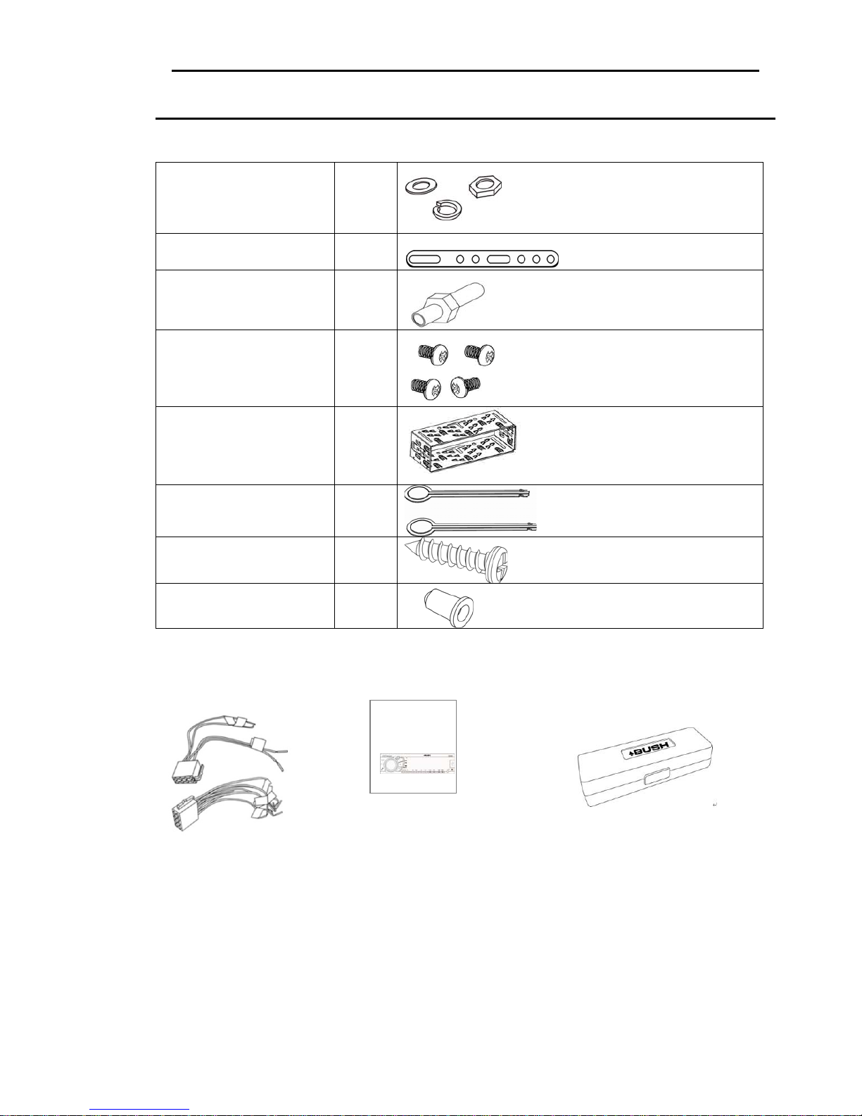
Accessories
Package will include in the following accessories for installation and operation of the unit.
(1) Washer, Sp r i n g Washer,
M5 Nut
1 each
(2) Mounting Strap 1
(3) Bolt 1
(4) Screw 4
(5) Mounting Collar 1
(6) Release Key 2
(7) Screw 1
(8) Rubber Cushion 1
ISO Cable A+B User Manual Panel with Carry Case
ICS11BTi
Page 5

ICS11BTi Instruction Manual
4
Installing the Unit into the ISO Dashboard Slot
Notes:
y Choose the mounting location where the unit will not interfere with the normal driving
function of the driver.
y Before finally installing the unit, connect the wiring temporarily and make sure it is all
connected up properly and the unit and the system work properly.
y Use only the parts included with the unit to ensure proper installation. The use of
unauthorised parts can cause malfunctions.
y Consult with your nearest dealer if installation requires the drilling of holes or other
modifications of the vehicle.
y Install the unit where it does not get in the driver’s way and cannot injure the passenger
if there is a sudden stop, like an emergency stop.
y If installation angle exceeds 30° from horizontal, the unit might not give its optimum
performance.
y Avoid installing the unit where it would be subject to high temperature, such as from
direct sunlight, or hot air, from the heater, or where it would be subject to dust, dirt or
excessive vibration.
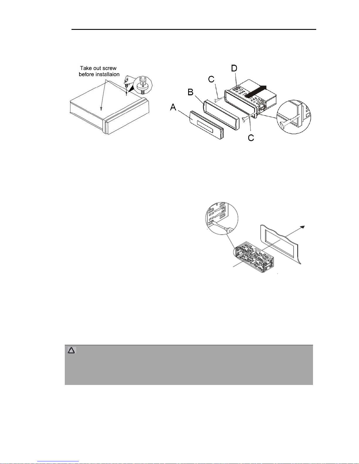
DIN FRONT/REAR-MOUNT
This unit can be installed either from “Front” (conventional DIN Front-mount) or “Rear”
(DIN Rear-mount installation, utilising threaded screw holes at the sides of the unit
chassis). For details, refer to the following illustrated installation methods.
TAKE OUT SCREW BEFORE INSTALLATION
Before installing the unit, please remove the two screws.
30
Page 6
ICS11BTi Instruction Manual
5
Installing the Unit
Detach the mounting sleeve (D) and frame (B) from the unit housing. Use the
assembly keys (C) to do so.
Fit the mounting sleeve into the ISO dashboard slot.
Bend the mounting sleeve tabs over with a screwdriver so that the frame is mounted
securely in the dashboard slot.
Check that the frame is secure.
Connect the ISO connection of the unit to
the two ISO connectors of your vehicle.
Connect the antenna cable of the vehicle
antenna to the antenna adapter of the
unit.
If necessary, also secure your unit
against theft. Fasten the screws to the mounting bracket and to the mounting
material on the engine firewall of the car.
Slide the unit carefully into the mounting sleeve, until it clicks into place.
After all connections have been made, press the RESET button using a ballpoint pen
or other pointed object.
Attach the control panel (A), as described under “Attach control panel“.
CAUTION:
Possible damage to the cables!
►When inserting the unit, pay attention to the cable routing to prevent damage.
►Then mount the frame.
Page 7

ICS11BTi Instruction Manual
6
1
2
Removing the Unit
To remove the unit, proceed as follows:
Remove the frame.
Insert the right and left hand assembly keys into the respective slots on the sides of
the unit. (The locking tabs are now released.)
Pull out the unit.
NOTE:
► If the housing is uneven, the tabs on the mounting sleeve may become
jammed. Use the assembly keys to release the tabs.
TO ATTACH THE FRONT PANEL
Hold the right side of the front panel with the plate facing
downwards.
First attach the left side of the front panel to the unit by
inserting the hole into the left holder.
Then slightly push it leftwards and attach the right side hole
into the right holder.
Finally push up the front panel.
Removing and protecting detachable front panel
The front panel of the unit may be removed as a theft
deterrent. After removing the front panel, use the case
provided to keep the front panel from getting damaged.
1. Press the OPEN button to flip down the front panel.
2. Grasp the right side of the front panel, and then gently
push the front panel towards the left side before pulling it
out from the unit.
3. Store the front panel in the protective case provided for
safe keeping.
Page 8
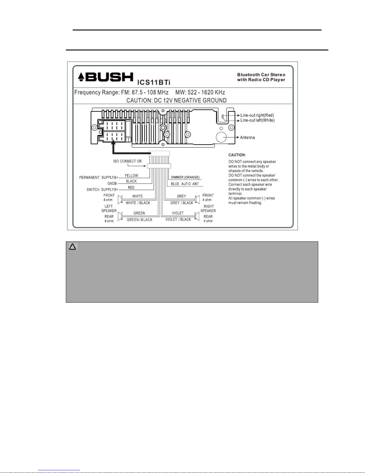
ICS11BTi Instruction Manual
7
Wiring Diagram
CAUTION:
12V DC NEGATIVE GROUND
Do not connect any speaker wires to the metal body or chassis of the vehicle.
Do not connect the speaker common (-) wires to each other.
Connect each speaker wire directly to each speaker terminal.
All speaker common (-) must remain floating.
WARNING: Do not interchange the connection of the wiring. Some car makes or models
may require special power harness other than provided. Contact your authorised car
dealer before installing this unit.
Page 9

ICS11BTi Instruction Manual
8
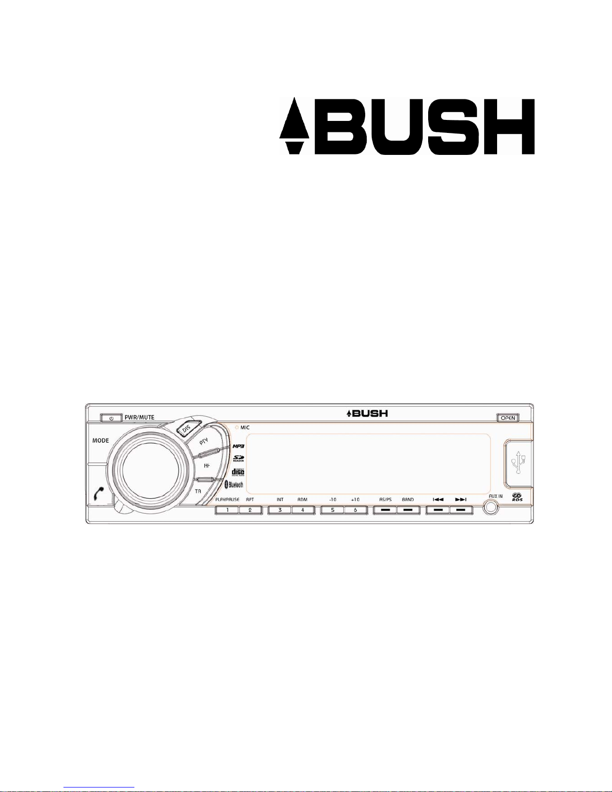
Operations
Location and function of keys for Front panel
The car radio after removing the front panel
1. Mode button
2. Power button
1. MODE
2. POWER/MUTE
3. VOLUME KNOB / PUSH SEL
4. DISPLAY MODE
5.PTY
6. LCD DISPLAY
7. OPEN
8. TELEPHONE PICKUP/HANGUP
9. TA/TP
10. AF/REG
11. PRESET 1/PAUSE
12. PRESET 2/ REPEAT
13. PRESET 3 / INTRO
14. PRESET 4 / RANDOM
15. PRESET 5/-10 TRACK
16. PRESET 6/+10 TRACK
17. AS/PS
18. BAND (FM/WM)
19. FAST REVERSE
20. FAST FORWARD
21. AUX IN JACK
22. USB SLOT
23. SD/MMC SLOT
24. EJECT
25. CD DISC LOADED
26. RESET
27. MIC
Page 10

ICS11BTi Instruction Manual
9
LCD Layout
1. Stereo reception indicator.
2. Not applicable to this model.
3. Illuminates when a disc is inserted.
4. Not applicable to this model.
5. EQ type indicator.
6. Not applicable to this model.
7. Not applicable to this model.
8. Not applicable to this model.
9. Display shows information according to set mode.
10. TA (Traffic Announcement) function indicator
11. TP (Traffic Program) function indicator
12. PTY (Program Type) function indicator
13. LOUD (loudness) function indicator
14. EON (Enhanced other Network) function indicator
15. Mute function indicator
16. LOC function indicator
17. AF (Alternative Frequency) function indicator
18. INT (Introduction) function indicator
19. RPT (Repeat) function indicator
20. Equalizer graph
21. RDM (Random) play function indicator
22. Bluetooth function indicator
23. Illuminates when an SD or MMC card is inserted.
24. Illuminates when CD is playing.
25. Illuminates when a USB device is connected.
26. Indicating the played file is MP3
27. Indicating the played file is WMA
28. Preset station number indicator
Page 11

ICS11BTi Instruction Manual
10
General Operations
Resetting the unit
Operating the unit for the first time or after replacing the car battery, you must reset
the unit.
Press OPEN button on the panel to open the panel and press RESET button to
restore the unit to its original factory settings.
Power on/off
Press any button (except OPEN) to turn on the unit. Press and hold the PWR button
on front panel to switch the unit off.
Note: After the unit has been turned off, the volume level and radio current settings
will be memorized, and when you turn the unit on it will resume the stored status you
previously set.
Play Mode selection
Press the MODE button repeatedly to switch between inputs:
Tuner CD* USB/IPOD* SD* AUX IN
(* available only if there is media device in disc, SD, USB slot)
Volume control
Rotate Volume knob on front panel to adjust the volume to the desired level.
Turning the sound off
Press MUTE button on the front panel to turn the sound off, press it again to turn the
sound on.
Sound Adjustments
Press the Select button repeatedly to select the audio settings:
VOLUME BASS TREBLE BALANCE FADER
Rotate Volume knob to adjust each setting, the settings are saved automatically.
Note:
If the unit is turned off, all the settings of each mode will be saved.
If cutting off battery power or resetting the unit, all the settings will return to
factory default settings.
System set up menu
Press the Select button and hold for more than 2 seconds to access the system
setup menu mode, and then press the Select button to select the menu item in
sequence as follows:
IN VOL→ADJ→CLK→BEEP→TA VOL→EON→EQ→LOUD→LOC→REG→STEREO
→ALRM
Page 12

ICS11BTi Instruction Manual
11
Rotate the Volume knob to adjust each setting, and press Select button to confirm
the setting.
TA ALARM
TA SEEK or TA ALARM
(Search for traffic announcement/traffic announcement alarm)
- TA SEEK mode:
When a newly tuned station does not receive traffic information for 5 seconds, the
radio retunes to next station which has a different PI and which broadcasts traffic
information.
If, during the chosen retune time (30 seconds for a short retune or 90 seconds for a
long retune), the unit can no longer receive the current station which was
broadcasting traffic information, it will start to search for the next station that has the
same PI.
If no station with the same PI is found after one search cycle, the radio will search for
the next station broadcasting traffic announcements.
- TA ALARM mode:
Select this mode to switch off the automatic retune. The radio will then emit a double
beep sound (ALARM).
If a newly tuned station does not broadcast any traffic information for 5 seconds, a
beep can be heard.
If the unit can no longer receive the current station during the chosen retune time, a
beep sound can also be heard.
If a newly tuned station has no RDS signal, the message “PI SEEK” disappears.
Note: TP: Traffic Program.
PI: Program Identification.
TA VOL
Set traffic announcement volume level. Defaulted value Vol 30
BEEP 2ND
BEEPS 2ND or BEEP ALL or BEEP OFF
The car audio device is equipped with 3 beep tone modes.
- Beep 2nd mode: The beep sound will be heard when you hold down a button with a
dual function, which activates the second function of this button.
- Beep on mode: The beep sound is on when any key is pressed.
- Beep off mode: The beep sound is disabled.
Stereo/mono
Rotate the volume button to select loudness feature Stereo/Mono.
LOUD OFF
LOUD OFF or LOUD ON
Loudness function on or off
Page 13

ICS11BTi Instruction Manual
12
DX/LOCAL
DX or LOCAL
-DX: If you want information (traffic announcement) from all available stations
-LOCAL: If you only want to receive information (traffic announcement) from local
stations only
Note: RDS (Radio Data System) service availability varies with areas. Please
understand if RDS service is not available in you area, the following service is not
available either.
Tuner Operation
Band Selection
Press the BAND button to select your frequency band of choice in the following
sequence:
FM 1 FM 2 FM 3 MW1 MW2
When a new frequency band is selected, the last chosen frequency / station of that
frequency band will be heard.
Manual / Auto tuning
- Automatic search mode:
Press the or button briefly to launch the automatic search forwards or
backwards. The message “SEARCH” appears on the display. The radio will search
up or down for a strong signal radio station within the current band.
Press and hold the or button until “MANUAL” appears on display, it will
change into manual searching mode.
- Manual search mode:
Press the or button repeatedly to manually search upward or downward step
by step for the desired radio station within the current band. For fast manual
searching, press and hold the
or button.
In manual search process, if neither of these buttons have been pressed within 5
seconds, the radio will go to automatic search mode automatically.
To store / recall a preset radio stations
You can store up to a total of 18 FM or 6 MW radio stations in the memory, manually
or automatically.
- To store a station:
1. Select a band (if needed)
2. Select a station by or buttons, refer to auto / manual tuning.
3. Press and hold a Preset button (1-6) for at least 2 seconds.
Page 14

ICS11BTi Instruction Manual
13
- To recall a station:
1. Select a band (if needed).
2. Press a preset button (1-6) briefly to recall the stored station.
Automatic Preset
Press the AS/PS button for more than 2 seconds to start auto store. The radio will
scan from the lowest frequency, and automatically store the 6 strongest stations into
the preset memories.
When auto store is complete, the radio will start a preset scan of the 6 stations which
it has just stored
Scan the preset stations
Press the AS/PS button briefly to scan each preset station. If the field strength level is
more than the threshold level, the radio will hold at this preset station for 5 seconds
with sound output, then go to next station until all FM stations are scanned, finally the
radio will play the preset station where scanning started. The preset station number
will flash during the process. Press the AS/PS again to stop preset scan.
RDS (Radio Data System) Operations
The RDS data are the PI, PS, TP, PTY, TA and AF data.
PI (Program identification): Code for identifying the radio station.
PS (Program service): Name of the radio station.
PTY (Program type): Type of program such as news, Pop music, sports
etc.
TP (Traffic program): Code indicating a station broadcasting traffic
information.
TA (Traffic announcement): Function allowing the broadcasting of traffic
information.
AF (Alternative frequencies): Function allowing an automatic search for
the best alternative frequency available.
Alternative Frequencies (AF)
AF is a function which works with the help of the RDS
(Radio Data System) and can only be used for FM stations. The unit searches in the
background for the frequency giving the clearest reception for the preset station.
Press the AF button to switch AF on and press again to switch AF function off.
-AF is displayed: Function is activated and RDS-Information is received.
-AF flashes: No RDS information is received.
-AF is not displayed: Function is deactivated.
Regional program
At certain times, some stations split their schedules into regional program with
differing content.
To play only the regional program of the station, Press and hold the AF button until
REG ON appears on the display.
Page 15

ICS11BTi Instruction Manual
14
To switch back to the networked program again, press and hold the AF button until
REG OFF appears on the display.
Program type (PTY)
Alongside the station name, some FM stations also give information on the program
type of their program. You can search for stations of a specific type.
Short press the PTY button to turn the PTY on/off.
Long press the PTY button and rotate the Volume control to display the required PTY.
Press or buttons to search for a station broadcasting this type of program
and it will stop searching if it finds the relevant program type. If the radio does not find
a station broadcasting the type of program selected, the text “PTY NONE” is
displayed and the previous station is broadcast.
Program type (PTY)
These are some examples of program types (Long press the PTY button):
POP M, ROCK M, CLASSICS, JAZZ, COUNTRY, NEWS, AFFAIRS, SPORT,
EDUCATE, DRAMA, CULTURE, SCIENCE, WEATHER, FINANCE, SOCIAL,
RELIGION, TRAVEL, LEISURE, DOCUMENT
Radio traffic service (TA - “Traffic Announcement“)
It is possible to program the car radio so that it interrupts current playback mode or
the current radio station when a traffic announcement is broadcast.
Briefly press the TA button to switch TA mode on, press again to switch TA mode off.
When TA mode is on, the unit automatically broadcasts available traffic
announcements and when the announcement ends the unit will return to the previous
playback mode. To interrupt a traffic announcement without switching off the TA
mode, briefly press the TA button. The radio will then return to the previous operating
mode.
CD - USB/iPod - SD Card Operation
Loading DISC
1. If there is no CD disc inserted in the player, press the OPEN button on the front
panel to flip down the front panel, then gently insert a CD disc with the printed side
facing up into the disc slot until you feel some resistance. The disc is drawn into the
unit automatically. The CD playback begins.
2. If a CD disc is already inserted in the player, press the MODE button to switch to
the CD mode.
3. To eject the CD from the player, press the OPEN button on the front panel to flip
down the front panel, then press the Eject button the disc will slide out of the unit
Inserting a SD/MMC card
1. Press the OPEN button on the front panel to flip down the front panel
Insert the SD/MMC card into the SD/MMC slot. The player will read and automatically
play the SD/MMC card.
Page 16

ICS11BTi Instruction Manual
15
2. To eject the SD/MMC card, press the OPEN button on the front panel to flip down
the front panel, then gently press the edge of the SD/MMC card to release the
SD/MMC card from the slot.
Inserting a USB device
Pull away the cap covering the USB connector and insert the USB device, the unit will
search for the MP3 files and play them automatically.
Note: When SD/MMC card and USB device are both inserted, the playing mode will
select the last device connected.
CD/MP3 Operation
Play/Pause track
The unit will automatically play from the first sound track recorded on a disc/SD/MMC
/USB device. To ensure good system performance, wait until the unit finishes reading
the disc /device information before proceeding. Press PLAY/PAUSE button on the
front panel to break the playback, press it again to resume playback.
Note: There may be a time delay in reading media that contains many files and
folders.
Select track
1. Press the or button to select the next or previous track. The track
number and the elapsed playing time are shown on the display.
2. Press the 5 / -10 button or 6 / +10 button to rewind or skip 10 tracks. The track
number and the elapsed playing time are shown on the display.
Fast forward/rewind
Keep the or button pressed to start fast forward or rewind.
Note: No Audio when in search mode.
Intro playback
1. Press the 3 / INT button. “INT” is shown on the display. All tracks are played in
sequence for around 10 seconds. Press the button again to resume normal
playback.
2. For MP3 files and CDs in MP3 Format only: Press and hold the 3 / INT button. All
tracks of the current folder are played in sequence for around 10 seconds.
“D-INT” and the current tracks were shown on the display. Press the button
again to restore normal playback.
Repeat function
1. Press the 2 / RPT button to repeat the current track. “RPT” is shown on the
display. Pressing the button again resumes normal playback.
Page 17

ICS11BTi Instruction Manual
16
2. For MP3 files and CDs in MP3 format only: Press and hold the 2 / RPT button
pressed to repeat the current folder. “D-RPT” and the current track are shown on
the display. Press the button to restore normal playback.
Random function
In disc mode press 4 / RDM button to activate random playing mode, press once
more to return to normal playing.
ID3 TAGS DISPLAY
Press the DIS button repeatedly to show ID3 tags information if the file has this
information.
Note: Pressing the DIS button on the front panel will show the following current
tuning information and time: CT (Clock/Time) ~ ID3 TAGS (only MP3 file with ID3
TAGS Information is available) ~ PTY ~ Radio Frequency ~ PS
File Search functions
Search for track number
1. Press the AS/PS button
2. Turn the Volume knob until the required track number is shown on the display.
3. Press the BAND button or Select button to confirm the selection. The unit
searches for the selected title number and plays it.
Search for track or directory name
Press the AS/PS button twice
Turn the Volume knob button until the required character is shown on the display and
confirm the setting by pressing the Select button.
1. Repeat this step until you have entered the required sequence of characters.
2. Press the BAND button to confirm the selection. The tracks which begin with the
entered sequence of characters are displayed.
3. Turn the Volume knob to select the required title or required directory from the
search results and press the Select button to confirm the selection and start
playback.
Search from the main directory
1. Press the AS/PS button three times.
2. Turn the Volume knob to select the required directory (ROOT = main directory).
3. Confirm your selection by pressing the Select button.
4. Turn the Volume knob to select the required title.
5. Confirm your selection by pressing the Select button. Playback begins.
Page 18

ICS11BTi Instruction Manual
17
iPod/iPhone Operation
Original iPod cable
Using your own original iPod/iPhone connection cable to connect to the USB socket
on the panel to play back iPod/iPhone audio. The unit turns to iPod/iPhone mode
automatically when an iPod is connected.
To start iPod/iPhone MODE in other modes, press MODE button repeatedly to switch
to iPod/iPhone mode.
(iPod cable is not included. )
Important note:
- When an iPod/iPhone is connected to the unit, the controls on the iPod/iPhone
are disabled.
- Current setting or play mode such as play lists may influence the playing order on
first connection to the device.
- Some characters may not be correctly displayed.
CAUTION: iPod/iPhone Operation playback is the same as CD/MP3 files. To
understand its operation, please see CD/MP3 operation section.
iPod-Menu
The unit can use the search function to search for songs from the iPod Menu.
1. Press the AS/PS button to activate the search function.
2. Turn the Volume knob to open a submenu:
Play list Artist Album Songs Genre Composer.
3. Press the Volume knob to confirm the selection. Turn the Volume knob to select
the required title.
Note: On some iPods and iPhones an option for downloading an APP will appear on
your device. This is for enhance iPod/iPhone operation control but not esentral for
your device to work with the ICS11BTi.
Before operation, you must downloading and install the APPs first in your device.
Page 19

ICS11BTi Instruction Manual
18
Bluetooth Operation
Bluetooth is a technology for wireless radio connection of devices over short
distances. Bluetooth technology enables hands-free use of mobile phones. The driver
can hold a conversation via his mobile phone without having to hold it to his ear.
This unit offers you the option of using a Bluetooth-enabled mobile phone. The
function radius is limited to around 3 meters depending on the device.
Do not set the volume too high. Doing so may lead to feedback (whistling) from the
speakers.
Telephone Operation
Pairing devices (PAIRING)
Before you can use the car radio to make phone calls, you must pair the units.
Select the Bluetooth menu in your mobile phone and register the car radio in your
mobile phone. To do so, refer to the user manual of your mobile phone. The
device pairing name displays on your mobile phone.
Depending on the device manufacturer, model and software versions, now enter
the password “0000“ in your mobile phone.
When pairing has been completed successfully, “CONNECT” will appear on the
LCD screen.
Disconnect your previous device before pairing another device.
This unit does not have the function to disconnect the Bluetooth with a paired
phone, when unpairing is required it must be disconnected at the phone.
Music playback via A2DP
This involves a cross-manufacturer Bluetooth profile. Stereo-audio signals are
transmitted by wireless via streaming between the playback unit (source) and
receiver unit.
To control the source remotely, the playback unit must support the AVRCP profile
(Audio Video Remote Control Profile).
Full functionality cannot be guaranteed due to the different unit manufacturers,
models and software versions.
After you have connected the units to each other, start playing the music in your
mobile phone.
Use the
or button to select the next or previous track.
If the car radio is turned off or the device goes out of range, after reconnection if
the BT Audio mode is selected, some phones require PLAY pressing twice to start
the song, and some phones will only need one press, this is dependent on the
brand of cell phone.
Redial
The unit stores the last dialed number. To access this, proceed as follows: Short
press BT key to go into BT menu and rotate the VOL knob to show the sequence in
below: CALL LIST --> L-DAI.
When CALLLIST is shown on the display, press BT key to go to BT menu. Rotate
VOL knob to choose phone number and then press the BT key to dial out the number.
Page 20

ICS11BTi Instruction Manual
19
When L-DIAL is shown on the display, press BT key on the front panel to call the last
number. The LCD display “DIALING” and phone display phone number and name if
the number stored to phone book.
Incoming call
In coming a call the LCD display phone number and name if the number stored to
phone book, when the number not stored to phone book the LCD display phone
number only. If the name and phone number more than 10 letter the LCD will scrolling
display. Press BT key to answer the phone, and press again to end the phone.
Note: When the unit power off, it will automatically switch to radio mode when it
powered on.
Handling & Cleaning DISC
Handling
- Dirty, scratched or warped discs may cause skipping or noise.
- To keep the disc clean, only handle the disc by its
edges.
- Discs should be stored in their cases after use to
avoid scratches.
- Do not expose discs to direct sunlight, high
humidity, high temperature or dust.
- Prolonged exposure to extreme temperature can warp the disc (such as leaving
the discs in your car in summer heat).
- Do not stick or write anything on either side of disc. Sharp writing instruments, or
the ink used in some felt-tip pens, may damage its surface.
- Do not touch the unlabelled side. Do not attach any seal, label or data protection
sheet to either side of a disc.
Cleaning DISC
Fingerprints should be carefully wiped from the surface
of disc with a soft cloth. Unlike conventional records,
compact discs have no grooves to collect dust or dirt, so
gently wiping them with a soft cloth should remove most
dust or stains. Wipe in a straight motion from the centre
to the edge.
CAUTION: Never use a thinner benzene, record cleaner or anti-static
spray on a compact disc. Such chemicals can damage its plastic
surface.
Page 21

ICS11BTi Instruction Manual
20
Troubleshooting
This chapter contains important advice on identifying faults and troubleshooting.
Follow the instructions to prevent hazards and damage.
Symptom Cause Solution
No power The car ignition is not
on.
Check correct power connection
to the car accessory, switch the
ignition key to “ACC”.
The fuse is blown. Replace the fuse.
No sound Volume is at minimum. Adjust volume to a desired level.
Wiring is not properly
connected.
Check wiring connection.
Bad sound quality The installation angle is
more than 30 degrees.
Adjust the installation angle to
less than 30 degrees.
The disc is defective or
extremely dirty.
Clean the compact disc/try to
play a new one.
Disc cannot be
loaded or ejected
The unit already
contains a disc.
Remove the disc in the player
then insert a new one.
Moisture condensation. Leave the unit idle for an hour,
then retry.
Disc cannot be read The disc is inserted
upside down.
Insert the compact disc with the
label side facing upward.
Compact disc is
defective or extremely
dirty.
Clean the disc or try to play a
new one.
Temperature inside the
car is too high.
Cool off until the ambient
temperature returns to normal.
Buttons do not work Some or none of the
buttons operating
correctly.
Install the front panel correctly.
Buttons do not work Internal processor
needs resetting
Reset the unit by pressing the
RESET button.
The radio does not
work
The antenna cable is
not connected.
Insert the antenna cable
correctly.
Bluetooth cannot be
paired
Password is not correct Check the passwords
Mobile phone is not on
bluetooth
Check that the phone is on the
bluetooth
The radio station
automatic tuning
does not work
The signals are too
weak.
Select stations manually.
Page 22

ICS11BTi Instruction Manual
21
Technical Data
General
Input voltage 12 V
Power consumption 10 A
Operating temperature +5 ~ +40 °C
Humidity (no condensation) 5 - 90 %
Dimensions (L x W x H) 178 x 175 x 50 mm
Weight 1.5 kg
Maximum power output 4 x 40 W (at 14.4 V)
Radio
Frequency range FM 87.5 - 108 MHz
Usable reception (FM) 9 µV
Channel separation >25 dB
Frequency range (MW) 522 - 1620 kHz
Usable reception (MW) 28 dBu
CD-Player
Signal to noise ratio 65 dB
Frequency response 20 Hz - 20 kHz
MP3 format requirements
Compression rate 16 - 320 kBit/s
Sampling rate 44.1 kHz
Specifications are subject to change without notice. Dimensions are approximate.
Page 23

ICS11BTi Instruction Manual
22
Contact Details
We trust you are completely satisfied with this production from Argos Ltd, however
please feel free to contact us if you experience any difficulties, or if you would like to
express your views regarding our products.
Please write to:
Customer Service
Argos Ltd
489-499 Avebury Boulevard
Saxon Gate West
Central Milton Keynes
MK9 2NW
Tel : 0870 600 3030
Through the process of continuous improvement, Argos Limited reserves the right to
change or alter specifications without prior notice. E&OE.
Page 24

ICS11BTi Instruction Manual
23
Product Guarantee
 Loading...