

Page 1
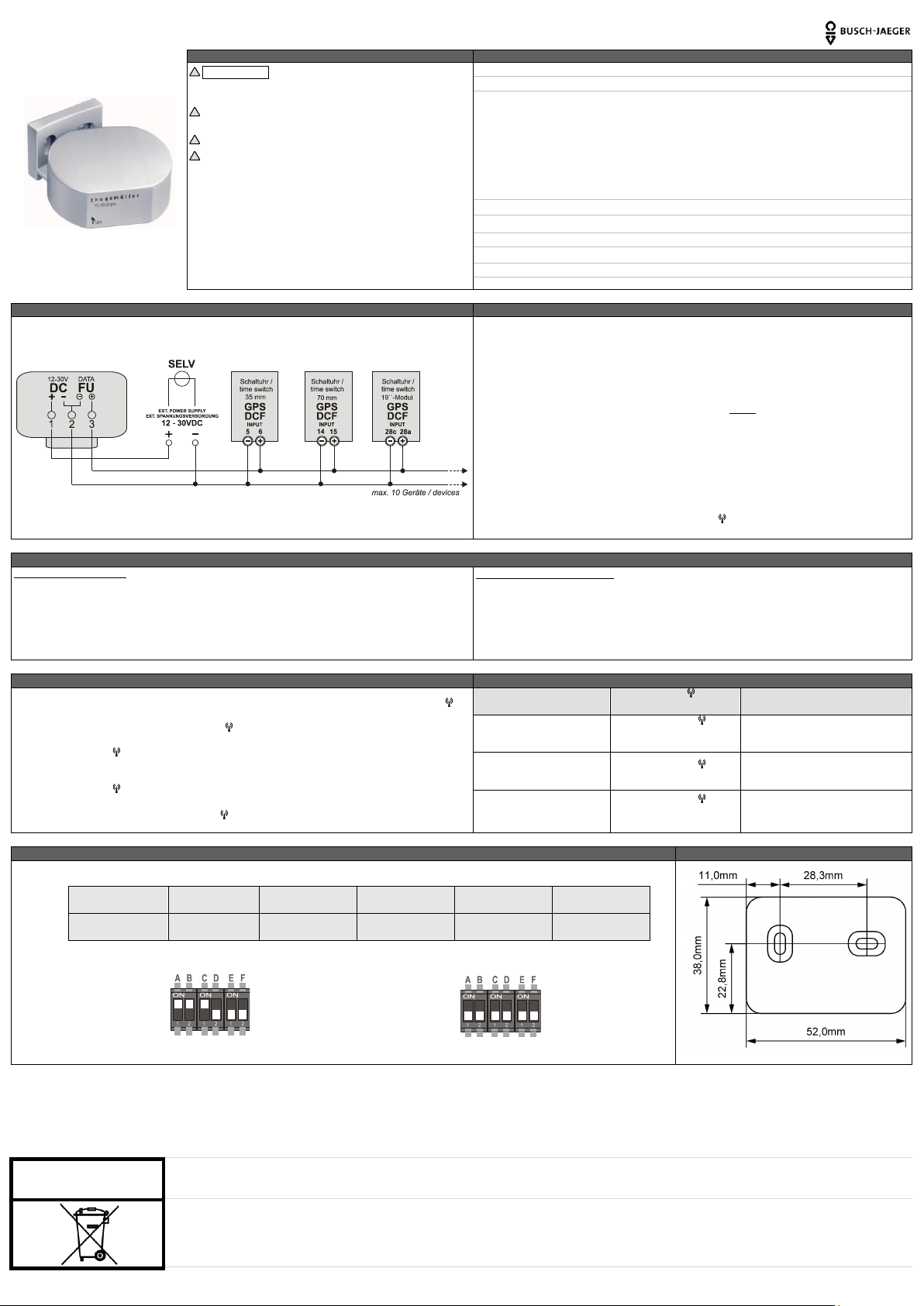
Funkempfänger GPS-Zeit 6144/41
Sicherheitshinweise
Technische Daten
!
!!!WARNU NG!!! Es besteht Brandgefahr o der die Gefahr eines
elek trischen Sc hlages! Einbau und Montage dürfe n ausschließli ch
von einer E lektrofachk raft durchgefüh rt werden!!!
!
Nur an die auf dem Gerät angegebe ne Spannung
und Frequen z anschließ en!
!
Bei Eingriffen oder Änderu ngen erlischt d ie Gara ntie!
!
Das Gerä t ist so zu instal lieren, dass au ch außergewöhnli ch hohe
Stör strahlu ng die Funktion nicht beeinträchtigen kann!
Anschlu ss-Spannung 12 - 30V / DC (max. 10,8 - 32V / DC) // Versorgu ng = Ex tern
Stro maufnahme Ø 30mA bei 12V / 15 mA bei 30V
Ausgangssignal DCF Zei t-Telegramm (keine Wetterdaten)
P olarität Au sgangssignal LOW aktiv
Ausga ngstyp Open Collec tor Beschaltung:
Umax. 50 V DC
Imax. 80 mA
Max. Ausgang sleistung 2 00 mW
A usgangsspannung LOW 2,5 V DC
Schu tzart IP 54 nach D IN EN 60529
Umge bungste mperatur -30°C … 55°C
Vorschriften // Prüfzeich en EN 607 30 // CE
Gehä use selbst verlöschendes Thermoplast
Montageart Wandaufbau mit Befestigung swinkel
Empfohlene( s) Kabel Abgeschirm t/Querschni tt 0,33 bis 2,5 mm2
Techn ische Ä nderung en vor behalte n
Anschlussbild
Installationshinweis
Der GPS -Empfänger ist so zu installieren, dass keine Hindernisse (Bäume / Wände / Decken / etc )
zwischen Geräteoberseite und Himmel einen s törungsfreien E mpfang beeinträ chtigen können.
Inne rhalb eines Umkreises von 1m um den GPS -Empfänger dür fen keine T ransformatoren, Rel ais,
Schü tze ode r dergleichen i nstalliert sein. Falls sich in diesem Umkreis ei ne Leuc htstoff -Lampe befindet,
muss gewährleistet sein, d ass die se hin und wieder ausgeschalte t ist, damit währe nd der A usschaltzeit e in
korr ekter Empfang möglich wird.
Bei Wandmon tage sollte diese frei von elektrisch en Leitungen und störenden Me tallkörpern sein.
Blin kt die LED auf der Ge räteunte rseite des Empfängers NICHT :
Falschanschluss / Anschluss überprüfen
Blin kt die LED auf der Geräteunte rseite des Empfängers schnell (5 Hz Takt) :
Korrekter Ansch luss / Suche nach GPS -Signal (Bis zu 15 Minuten)
Blin kt die LED auf der Geräte unterse ite des Empfän gers la ngsam (Sekunden takt):
Korrekter Ansch luss / Signalempfang OK
Sollte die LED auf der Geräteunte rseite des Empfängers nach mehr a ls 15 Minuten immer noch
schnell blinken (5 Hz Takt): Eventue ll kein korrekter Empfang des GPS-S ignals. Bitte suchen S ie einen
ande ren Sta ndort.
Bis die Schaltu hr syn chronisi ert und das FU /GPS-Symbol im Uhren-Display permanent angezeigt wird
können mehrer M inuten vergehen.
Montage und Anschluss des Gerätes
Ansc hluss / Wan dmontage
Beide Schra uben an der Un terseite de s Gehäuses löse n und Grundplatte abheben.
Kabe l durch die beiliegende Kabeltülle und durch die Öffnung de r Grundplatte führen.
Kabe l entsprechend Anschlussbild mit Klemmen block verbinden.
Kabe ltülle ents prechend in die Öffnung der Grun dplatte montieren.
Gehä use wieder mit der Grundplatte ve rschrauben.
Befe stigung swinkel an der Wand ve rschraub en und Funkemp fänger a ufstecken (siehe Bohrp lan).
Kabe l und Verlegung de s Kabels
Funk empfänger u nd Uhr sind so mit einander zu verbinden (Siehe Ansc hlussplan), dass die Leitungen
nich t zwischen der Mon tagewand und dem Funke mpfänger verlau fen.
Max. Kabellänge : 200m
Kabe ldurchmesser: 0,33 bis 2,5 mm2
Para llelver legung zu a nderen Leitunge n ist zu vermei den (Strom, Telefon, e tc.)
EMPFEHL UNG: Verwendung eines geschirmten Kabels
Displayanzeige der Schaltuhren (bei Funkempfang)
Erläuterung LED GPS-Empfänger // FU/GPS-Symbol in der Displayanzeige der Schaltuhr
Die Schaltuhren zeigen nach dem Annschluss des GPS -Empfänger s durch Blinken des FU /GPS-S ymbols im
Scha ltuhren -Displa y an, d ass eine Verbindung zw ischen beiden Gerä ten vorhanden i st.
BITT E BEACHTEN SIE : Bis das FU/GPS-Symbol nach dem Ansch luss de s GPS-Empfängers an d ie
Scha ltuhr zum ersten Mal i m Uhren -Display e rschein t/blinkt, k ann es bis zu 15 Minu ten dauern.
Das FU/ GPS-Symbol kann bis zu 5 Minuten im Display blin ken bi s es nach erfolgrei cher Zeitsynchronisati on
permanent angezeigt wi rd.
Empfängt die GP S-Antenne kein Signal , laufen die Sc haltcomputer in tern qu arzgenau weiter .
Das FU/GPS -Symbol wird nicht angezeigt.
!!PE RMANENTE ANZEI GE DES FU/GPS-Symbols IM UHREN DISPLAY = SCHATUHR SYNCHRO NISIERT!!
LED auf der Unterseite des
GPS- Empfän gers
FU/G PS-Symb ols im
Schaltuhren -Display
STATUS
LED AUS
Das FU/ GPS-Symbol ist
nicht i m Schaltuhren-Disp lay
zu sehen
=> Keine Spannu ngsversorgu ng
=> Fals chanschluss
LED blinkt schnell
(5 Hz)
Das FU/ GPS-Symbol im
Scha ltuhren -Displa y blinkt
=> Suche de s GPS-S ignals
=> Synchron isierung läuft
LED blinkt langsam
(Sekunde ntakt)
Das FU/ GPS-Symbo l im
Scha ltuhren -Displa y wird
permanent angezeigt
=> Gültiges GPS -Signal
=> Schaltuhr is t synchronisiert
Erläuterung DIP-Schalter // Schalterpositionen
Bohrplan für Wandhalter
!!!NICHT MAßSTABSGERECHT!!!
Schalte r A
Schalte r B
Schalte r C
Schalte r D
Schalte r E
Schalte r F
ON
Sommer / Winterzei t-
umstellung EIN*
GMT-Vorzeichen [+]
GMT Verschiebun g
1 Stunde
GMT Verschiebun g
2 Stunden
GMT Verschiebun g
4 Stunden
GMT Verschiebun g
8 Stunden
OFF
Sommer / Winterzei t-
umstell ung AUS *
GMT-Vorzeichen [-]
Keine
Verschiebun g
Keine
Verschiebun g
Keine
Verschiebun g
Keine
Verschiebun g
*Eur opäisc he Somm er / W interz eitrege l
Eins tellung für Ausgan gssignal = D CF [Auslieferungszusta nd]
[Bit te bea chten Sie da s das D CF Sig nal kei ne Wet terdat en ent hält]
Eins tellung für Ausgan gssignal = Weltze it UTC [GMT]
Nehmen Sie Rücksicht auf unsere
Umwelt! Entsorgen Sie die Geräte
umweltgerecht!
Funkempfänger GPS-Zeit - 0073-1-8546 Busch-Jaeger Elektro GmbH, Freisenbergstraße 2, 58513 Lüdenscheid, Tel: 02351 956-1600, www.BUSCH-JAEGER.de
Page 2
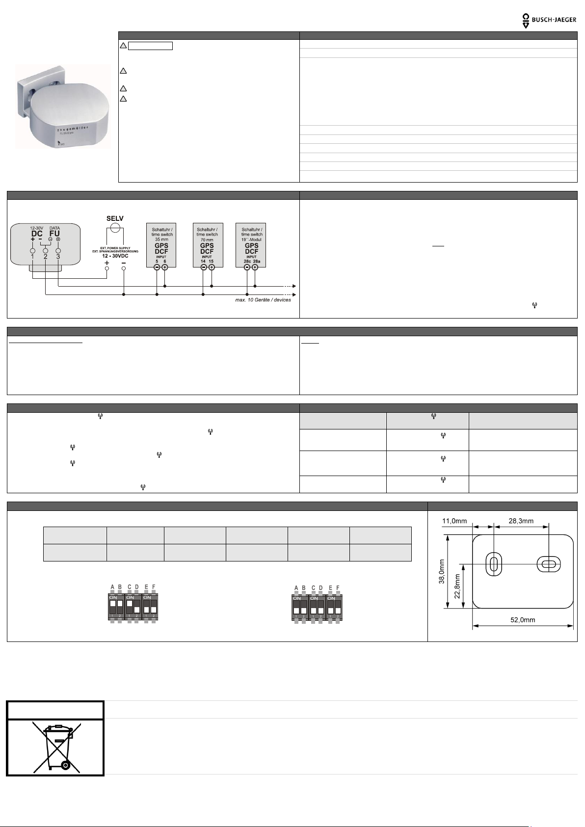
Radio receiver GPS-time 6144/41
Safety issues
Technical data
!
!!!ATTEN TION!!! Risk of fire and electric shoc k! Installatio n and
assembly of electr ical equ ipment must b e carried out by skilled
person!!!
!
Connect the supply voltage /frequency as stated o n the produ ct
label!
!
Warrant y void i f housing opened by u nauthorised person !
!
The electronic circuit is protected a gainst a wi de range of external
infl uences. Incorrect oper ation may o ccur if external influences
exceed certain limits!
Supp ly voltage 12 - 30V / DC (max. 10,8 - 32V / DC) // supply = extern
Power co nsumption Ø 30mA a t 12V / 15 mA at 30V
Output signal DC F time tele gram (no we ather d ata)
Polarity output sign al LOW activ
Ou tput ty pe Open Collec tor wir ing:
Um ax. 50 VD C
Im ax. 80 mA
Ma x. output power 200 mW
Ou tput voltage L OW 2,5 VDC
Protection type IP 54 to DIN EN 60529
Ambient tempera ture -30 °C … 55° C
Specifications // Compliance EN 60730 // CE
Housing self-e xtingui shing thermopla st
Asse mbly wall mount ing with mo unting bracket
Reco mmend wire sh ielded/cross-secti on 0,33 to 2,5 mm2
Sub ject to techni cal cha nges
Connection diagram
Installation instruction
Make sure that the GPS time re ceiver (top o f the devic e) has free view to sky. Trees, wall s, and so on, can
severely degrade the s atellite re ception capabil ity of the rece iver.
Make sure that there a re no transform ers, re lays, switches, or similar device s within a radi us of one meter
around the GPS time receiver.
If m ounted on wall , avoid electric ca bles and other disturb ing metal in the wa ll.
If t he LED on t he bott om side of the dev ice is NOT flashing:
Check prope r connection
The LED on the bottom side of the device is flas hing fa st (5 Hz):
Connection OK / devi ce is waiting for GPS sign al (can take up to 15 minutes)
The LED on the bottom side of the device is flas hing slow (1 Hz):
Connection OK / GPS signal OK
If t he LED on t he bott om side of the dev ice is flashing fast longer than 15 minutes (5 Hz):
Possibly no GPS signal. Try to use an alternative po sition.
It w ill take se veral minutes until th e time switch i s synchronized and the FU/GPS-symbol is displayed
permanently in the time switch.
Installation and connection of the device
Connection / wal l mounting
Remo ve both screws on the bottom side and remove the bo ttom cover.
Guide wire through the cable slee ve and the hole of th e botto m cover.
Connect wire wi th terminal block according to the ab ove con nection diagram .
Asse mble cable sleeve on the bottom cover.
Scre w the bottom cover .
Install wall mounting bracket and attach GPS tim e recei ver (see drilling plan).
Wiri ng
Connect GPS time receiver and time switch su ch that the wiring is not between the mounting wall and the
GPS time re ceiver.
Max. wire length: 200m
Wire cross-sec tion : 0,33 to 2,5 mm2
Avoid parallel placement with other c ables,e .g., electric cables, telephon e wires, and so on.
RECOMMENDATION : We re commend shielded wi res
Display of the time switch
Description LED GPS time receiver // FU/GPS-symbol of the time switch
Flashing of the FU/GPS-symbol in the display of the time switch in dicates proper connection betwe en time
switch and GPS time re ceiver afte r installation.
PLEASE OBSERVE: It can take up to 15 minute s until the FU/GPS-symbol appears/flashe s after connecting
the GPS time re ceiver to the time switch.
The FU/GPS- symbol may flash up to 5 minu tes while the time switch is bein g synch ronised . Eventually, a fter
synchronisa tion of the time switch, the FU/GPS -symbol is disp layed perma nently.
The FU/GPS- symbol is not shown, i f the GPS t ime receiver canno t receive a (valid) GPS signal. Ti me
accuracy of the ti me switch i s based on its internal quartz.
!!PE RMANENT DISPLAY OF THE F U/GPS-symbo l = TIME S WITCH IS SY NCHRONI SED!!
LED on the bottom side of the
GPS time re ceiver
FU/G PS-symbol of the time
switch
STATUS
LED off
The FU/GPS- symbol is not
visible in the display
=> No suppl y voltag e
=> Wrong connection
LED flashes fast (5 Hz)
The FU/GPS- symbol is
flah ing in the disp lay
=> Waiting for GPS signal
=> Synchron isation of time sw itch
LED flashes slow (1 H z)
The FU/GPS- symbol is
permanently visible
=> Valid GPS signal
=> Time switch is synchron ised
Description DIP switches // Switch positions
Drilling plan for wall mounting bracket
!!!NOT TRUE TO SCALE!!!
Switch A
Switch B
Switch C
Switch D
Switch E
Switch F
ON
Dayligh t saving time
ON*
GMT-offset [+]
GMT offset
1 hour
GMT offset
2 hour
GMT offset
4 hour
GMT offset
8 hour
OFF
Dayligh t saving time
OFF*
GMT- offset [-]
no
offset
no
offset
no
offset
no
offset
*European day light savin g time rules
Switch posi tion for DC F output si gnal [ default]
[Pl ease not e that the D CF sig nal is withou t weat her br oadcast! s]
Switch posi tion for UT C output si gnal [ GMT]
Take care of the environment!
Recycle properly!
Funkempfänger GPS-Zeit - 0073-1-8546 Busch-Jaeger Elektro GmbH, Freisenbergstraße 2, 58513 Lüdenscheid, Tel: 02351 956-1600, www.BUSCH-JAEGER.de
 Loading...