

Page 1
Instruction Manual
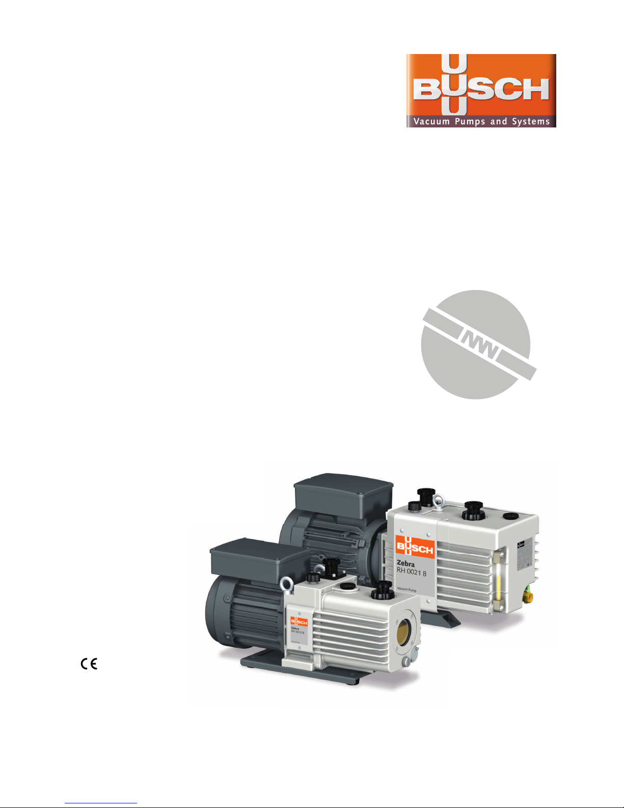
Zebra
Two-Stage Rotary Vane Vacuum Pumps
RH 0003 B, RH 0010 B, RH 0015 B, RH 0021 B
0870169116/-0002_en / Original instructions / Modifications reserved 09/09/2016
Busch Produktions GmbH
Schauinslandstraße 1, 79689 Maulburg
Germany
Page 2

Table of Contents
2 / 28 0870169116_RH0003-0021B_-0002_IM_en
Table of Contents
1 Safety........................................................................................................................... 3
2 Product Description ..................................................................................................... 4
2.1 Operating Principle...............................................................................................5
2.2 Application ........................................................................................................... 5
2.3 Standard Features.................................................................................................5
2.3.1 Gas Ballast Valve........................................................................................5
2.4 Optional Accessories............................................................................................. 6
2.4.1 Inlet Filter ..................................................................................................6
2.4.2 Oil Mist Separator......................................................................................6
2.5 Motor Variants ..................................................................................................... 6
3 Transport ..................................................................................................................... 6
4 Storage......................................................................................................................... 7
5 Installation................................................................................................................... 7
5.1 Installation Conditions .......................................................................................... 7
5.2 Connecting Lines / Pipes ......................................................................................8
5.2.1 Suction Connection....................................................................................8
5.2.2 Discharge Connection................................................................................9
5.2.3 Oil Mist Separator (Optional).....................................................................9
5.3 Filling Oil.............................................................................................................. 10
5.4 Electrical Connection ............................................................................................11
5.4.1 Wiring Diagram Single-Phase Motor..........................................................11
5.4.2 Wiring Diagram Three-Phase Motor ..........................................................12
6 Commissioning............................................................................................................ 13
6.1 Continuous Operation .......................................................................................... 13
6.2 Conveying Condensable Vapours ......................................................................... 14
7 Maintenance................................................................................................................ 14
7.1 Maintenance Schedule.......................................................................................... 14
7.2 Oil Change Recommendations .............................................................................15
7.3 Oil Change........................................................................................................... 16
7.4 Coupling Maintenance .........................................................................................18
8 Overhaul...................................................................................................................... 18
9 Decommissioning ........................................................................................................ 19
9.1 Dismantling and Disposal...................................................................................... 19
10 Spare Parts ................................................................................................................... 20
11 Accessories .................................................................................................................. 20
12 Troubleshooting........................................................................................................... 21
13 Technical Data ............................................................................................................. 23
14 Oil ............................................................................................................................... 23
15 EU Declaration of Conformity ...................................................................................... 24
Page 3

Safety | 1
0870169116_RH0003-0021B_-0002_IM_en 3 / 28
1 Safety
Prior to handling the machine this instruction manual should be read and understood. If
anything needs to be clarified please contact your Busch representative.
Read carefully before use and keep for future reference.
This instruction manual remains valid as long as the customer does not change anything
on the product.
The machine is intended for industrial use. It must be handled only by technically trained
personnel.
The machine has been designed and manufactured according to state-of-the-art methods. Nevertheless, residual risks may remain. This instruction manual highlights potential
hazards where appropriate. Safety notes and warning messages are tagged with one of
the keywords DANGER, WARNING, CAUTION, NOTICE and NOTE as follows:
DANGER
... indicates an imminent dangerous situation that will result in death or serious injuries if
not prevented.
WARNING
... indicates a potentially dangerous situation that could result in death or serious injuries.
CAUTION
... indicates a potentially dangerous situation that could result in minor injuries.
NOTICE
... indicates a potentially dangerous situation that could result in damage to property.
NOTE
... indicates helpful tips and recommendations, as well as information for efficient and
trouble-free operation.
Page 4
2 | Product Description
4 / 28 0870169116_RH0003-0021B_-0002_IM_en
2 Product Description
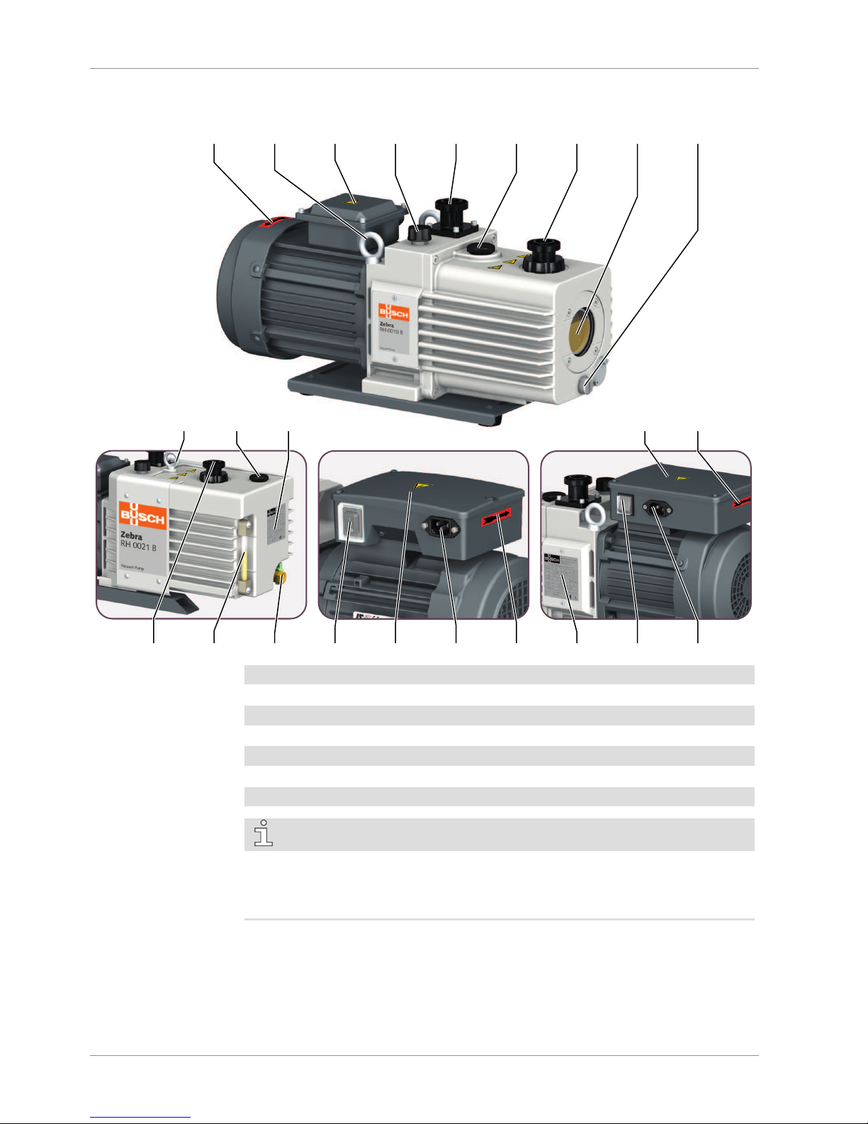
ODV
DA EB GB OFP OUT OSG ODP
OLI
MTB IN
RH 0010 B
(three-phase motor)
RH 0021 B
RH 0021 B
(single-phase motor)
RH 0010 B
(single-phase motor)
MCOOS OOSDAIN NP
EB OFP NP
MC
DAMTB
MTB
DA Directional arrow EB Eye bolt
GB Gas ballast valve IN Suction connection
MC Mains connection MTB Motor terminal box
NP Nameplate ODP Oil drain plug
ODV Oil drain valve OFP Oil fill plug
OLI Oil level indicator OOS On/off-switch
OSG Oil sight glass OUT Discharge connection
NOTE
Technical term.
In this instruction manual, we consider that the term ‘machine’ refers to the ‘vacuum
pump’.
Page 5
Product Description | 2
0870169116_RH0003-0021B_-0002_IM_en 5 / 28
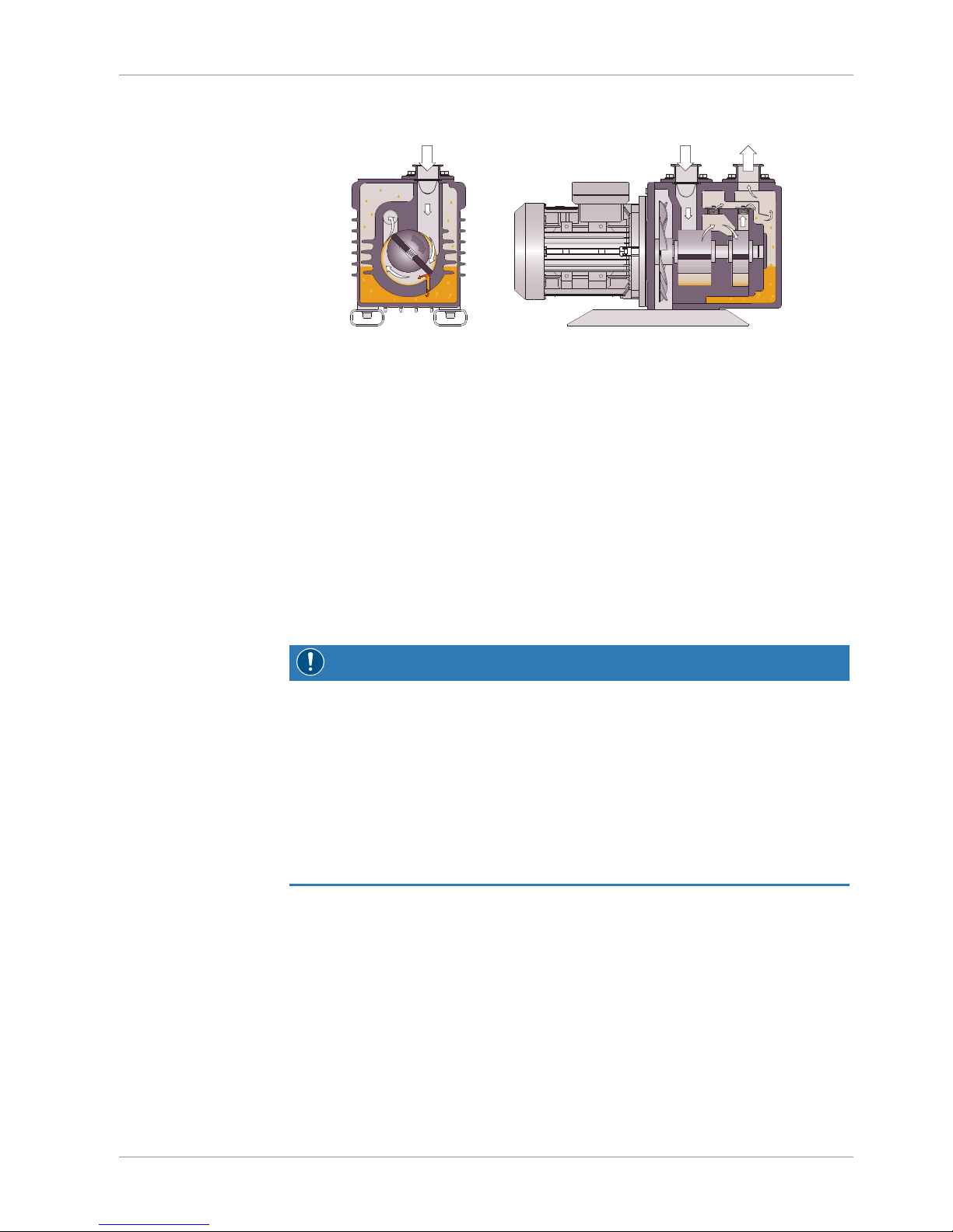
2.1 Operating Principle
The machine works on the two-stage rotary vane principle.
The oil seals the gaps, lubricates the vanes and takes away compression heat.
2.2 Application
The machine is intended for the suction of air and other dry, non-aggressive, non-toxic
and non-explosive gases.
Conveying of other media leads to an increased thermal and/or mechanical load on the
machine and is permissible only after a consultation with Busch.
The machine is intended for the placement in a non-potentially explosive environment.
The machine is capable of maintaining ultimate pressure.
The machine is suitable for continuous operation under certain conditions, see Continu-
ous Operation [}13].
Permitted environmental conditions see Technical Data [}23].
NOTICE
Chemical compatibility of the process gases with the machine component materials.
Risk of corrosion inside the compression chamber which can reduce performance and
its lifetime!
• Check if the process gases are compatible with those following materials:
- Cast iron
- Steel
- Aluminium
- Fluoroelastomer (FKM/FPM)
• In doubt, please contact your Busch representative.
2.3 Standard Features
2.3.1 Gas Ballast Valve
It mixes the process gas with a limited quantity of ambient air to counteract the condensation of vapour inside the machine.
Page 6

3 | Transport
6 / 28 0870169116_RH0003-0021B_-0002_IM_en
2.4 Optional Accessories
2.4.1 Inlet Filter
It protects the machine against dust and other solids in the process gas. The inlet filter is
available with a polyester cartridge.
2.4.2 Oil Mist Separator
To reduce the oil consumption and trap any oil mist, when operating at a high suction
pressure, it is recommended to fit an oil mist separator at the discharge connection
(OUT).
To allow the oil to return to the machine in continuous operation, please comply with
the conditions for Continuous Operation [}13].
2.5 Motor Variants
The Zebra RH 0003-0021 B are equipped with multi-voltages and multi-frequencies motors (50 Hz/60 Hz).
They can be delivered either with a single-phase or three-phase motor, except for
RH0003B which is only available with a single-phase motor.
3 Transport
WARNING
Suspended load.
Risk of severe injury!
• Do not walk, stand or work under suspended loads.
CAUTION
Handle the machine by hand.
Risk to injury!
• Do not lift by hand a machine heavier than 20 kg.
• Follow all safety provisions in order to prevent an accident.
NOTICE
In case the machine is already filled with oil.
Tilting a machine that is already filled with oil can cause large quantities of oil to ingress into the cylinder. Starting the machine with excessive quantities of oil in the
cylinder will immediately break the vanes and ruin the machine!
• Drain the oil prior to every transport or always horizontally transport the machine.
Page 7
Storage | 4
0870169116_RH0003-0021B_-0002_IM_en 7 / 28
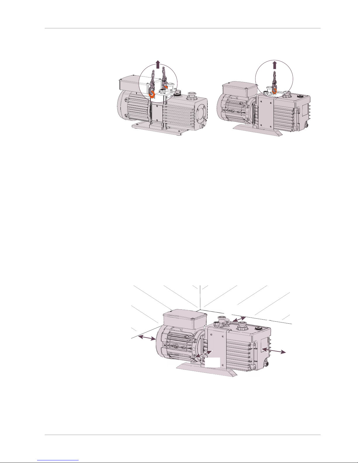
Machine weight:
see the technical data or the nameplate (NP)
For RH 0010 B and RH 0015 B:
For RH 0021 B:
For RH 0003 B:
Due to its light weight (16 kg / 35 lbs), it can be handled with care by hand
• Check the machine for transport damage.
In case of the machine being secured to a base plate:
• Remove the fixations.
4 Storage
• Seal all apertures with adhesive tape or reuse provided caps.
In case of storage of more than 3months is scheduled:
• Wrap the machine in a corrosion inhibiting film.
• Store the machine indoors, dry, dust free and if possible in original packaging
preferably at temperatures between 7 ... 40 °C (45 ... 104 °F), less than 85%RH
(relative humidity).
5 Installation
5.1 Installation Conditions
~10 cm
~3.93 in
~10 cm
~3.93 in
~10 cm
~3.93 in
~10 cm
~3.93 in
• Make sure that the environment of the machine is not potentially explosive.
• Make sure that the ambient conditions comply with the Technical Data [}23].
• Make sure that the environmental conditions comply with the protection class of the
motor.
Page 8

5 | Installation
8 / 28 0870169116_RH0003-0021B_-0002_IM_en
• Make sure that the installation space or location is vented such that sufficient cooling
of the machine is provided.
• Make sure that cooling air inlets and outlets of the motor fan are not covered or obstructed and that the cooling air flow is not affected adversely in any other way.
• Make sure that the oil sight glass (OSG) or the oil level indicator (OLI) remains easily
visible.
• Make sure that enough space remains for maintenance work.
• Make sure that the machine is placed or mounted horizontally, a maximum of 1° in
any direction.
• Check the oil level, fill up if necessary, see Filling Oil [}10].
• Make sure that all provided covers, guards, hoods, etc. are mounted.
If the machine is installed at an altitude greater than 1000 meters above sea level:
• Contact your Busch representative, the motor should be derated or the ambient
temperature limited.
5.2 Connecting Lines / Pipes
• Make sure that the connection lines cause no stress on the machine‘s connection, if
necessary use flexible joints.
• Make sure that the line size of the connection lines over the entire length is at least as
large as the connections of the machine.
In case of very long connection lines it is advisable to use larger line sizes in order to
avoid a loss of efficiency. Seek advice from your Busch representative.
WARNING
Internal pressure higher than 300 hPa (gauge).
Risk of severe injury!
Risk of damage to the machine!
• Make sure that the discharge line is not clogged (either pipe or oil mist separator).
5.2.1 Suction Connection
WARNING
Unprotected suction connection.
Risk of severe injury!
• Do not put hand or fingers in the suction connection.
NOTICE
Intruding foreign objects or liquids.
Risk of damage to the machine!
In case of the inlet gas contains dust or other foreign solid particles:
• Install a suitable filter (5micron or less) upstream the machine.
Connection size:
– ISO-KF 25
Page 9
Installation | 5
0870169116_RH0003-0021B_-0002_IM_en 9 / 28
5.2.2 Discharge Connection
CAUTION
The discharge gas contains small quantities of oil.
Risk to health!
If air is discharged into rooms where persons are present:
• Make sure that sufficient ventilation is provided.
Connection size:
– ISO-KF 25
– G3/4 (without ISO-KF adapter) for RH 0003 B
– G1 (without ISO-KF adapter) for RH 0010-0021 B
• Make sure that the discharged gas will flow without obstruction. Do not shut off or
throttle the discharge line or use it as a pressurised air source.
Unless the aspirated air is discharged to the environment right at the machine:
• Make sure that the discharge line either slopes away from the machine or provide a liquid separator or a drip leg with a drain cock, so that no liquids can flow back into the
machine.
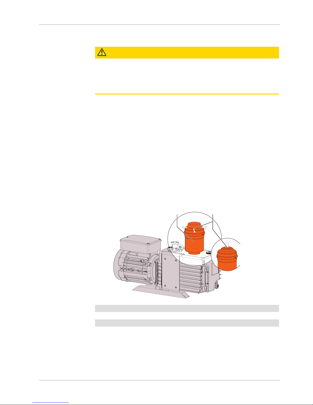
5.2.3 Oil Mist Separator (Optional)
The oil mist separator has to be fitted at the discharge connection.
• Remove the ISO-KF adapter.
• Mount the oil mist separator with its seal.
OMS OUT
Connection alternative:
A threaded connection
is possible by
unscrewing the oil mist
separator cap.
OMS 0003 Oil mist separator for RH 0003 B
OMS 0021 Oil mist separator for RH 0010-0021 B
OUT Discharge
Page 10
5 | Installation
10 / 28 0870169116_RH0003-0021B_-0002_IM_en
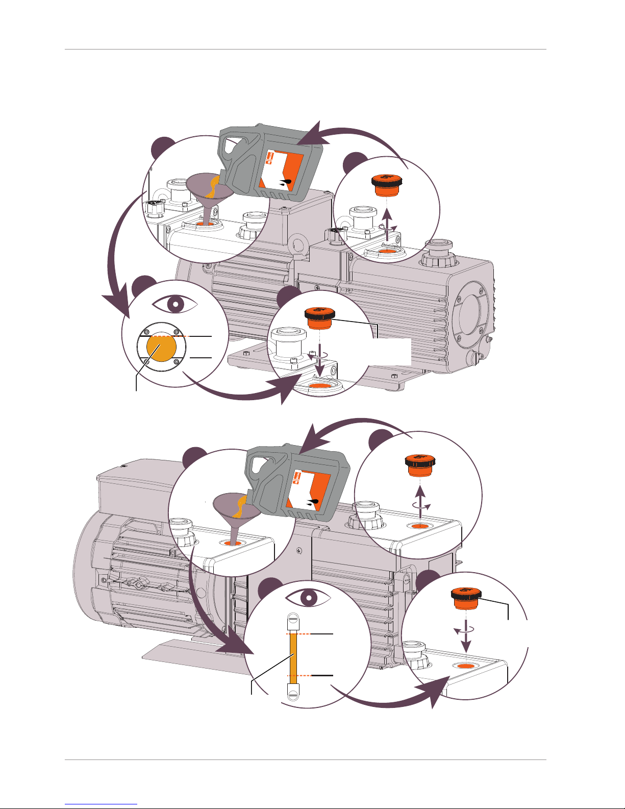
5.3 Filling Oil
For oil type and oil capacity see Technical Data [}23] and Oil [}23].
1
4
MAX
MIN
3
2
2
Busch Oil
2
Check oil level
Oil filling for RH 0003-0015 B:
Check the o-ring
if it is correctly
seated in the groove
MAX
MIN
3
2
2
Busch Oil
1
4
2
Check oil level
Oil filling for RH 0021 B:
Check the o-ring
if it is correctly
seated in the groove
Page 11
Installation | 5
0870169116_RH0003-0021B_-0002_IM_en 11 / 28
5.4 Electrical Connection
DANGER
Live wires.
Risk of electrical shock.
• Electrical installation work must only be executed by qualified personnel.
• Make sure that the power supply for the motor is compatible with the data on the
nameplate of the motor.
• Provide an overload protection according to EN 60204-1 for the motor.
• Make sure that the motor of the machine will not be affected by electric or electromagnetic disturbance from the mains; if necessary seek advice from Busch.
• Connect the protective earth conductor.
• Electrically connect the motor.
NOTICE
Incorrect connection.
Risk of damage to the motor!
• The wiring diagrams given below are typical. Check the inside of the terminal box for
motor connection instructions/diagrams.
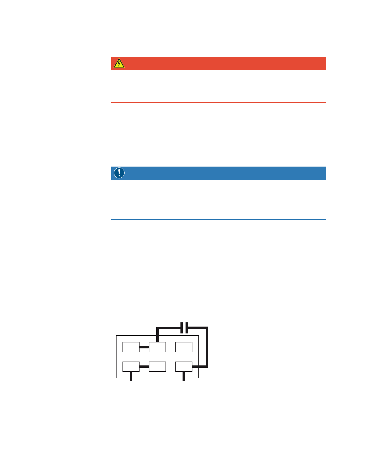
5.4.1 Wiring Diagram Single-Phase Motor
The motor is equipped with an auto reset thermal protector that turns off the machine at
120 ±5 °C.
If the protector has been activated:
• Solve the problem (see Troubleshooting [}21]).
• Let the motor cool down until a temperature of 78 ±9 °C.
• Restart the machine.
For RH 0003 B:
• Electrically connect the motor according to the following wiring diagram:
Connector type: Quick-connect terminal (#250)
21 3
54 6
L N
For RH 0010-0021 B:
• Electrically connect the motor directly to the mains connection (MC).
Connector type: EN 60320-C13 (AC plug for Europe included)
Page 12
5 | Installation
12 / 28 0870169116_RH0003-0021B_-0002_IM_en
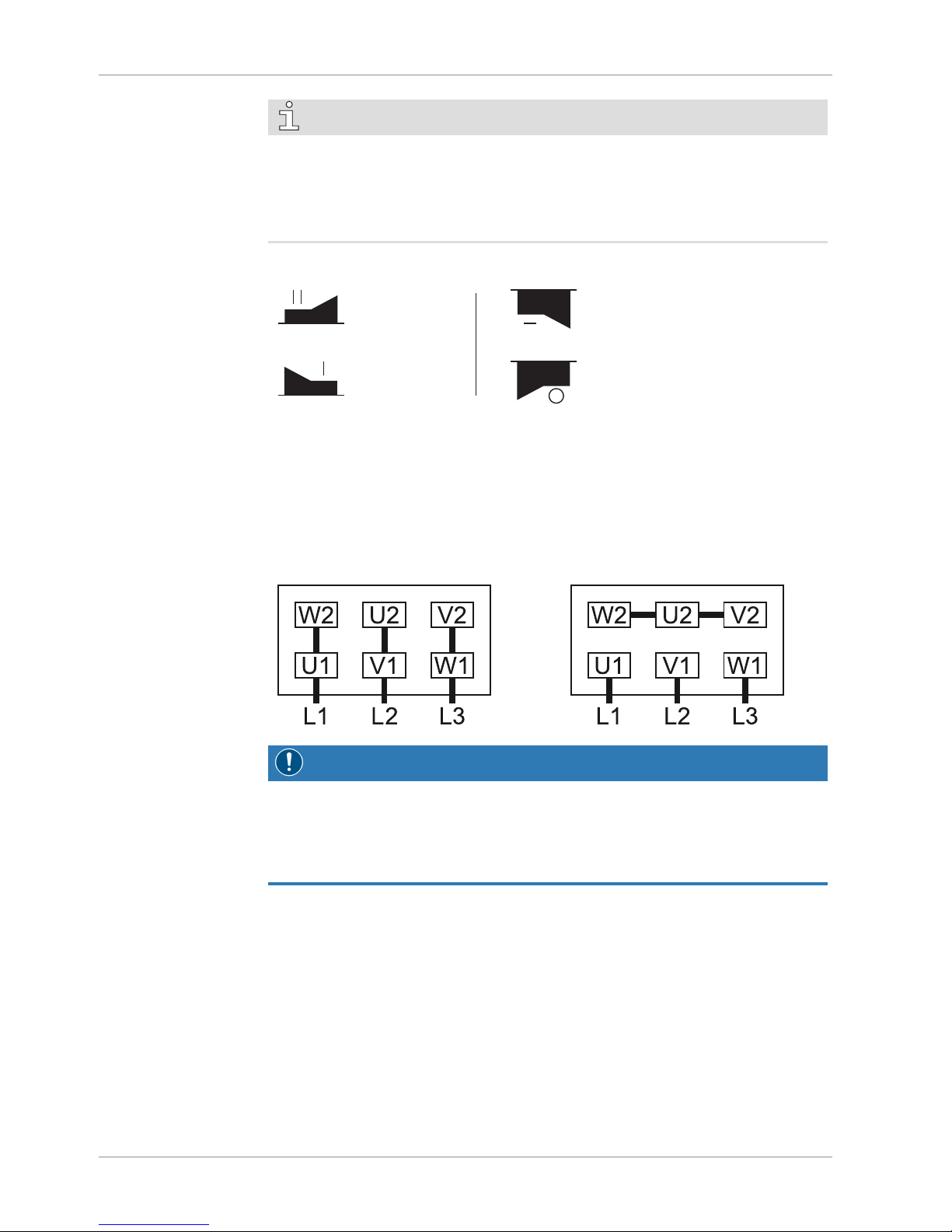
NOTE
The factory default voltage class is set for 200-240 V use.
If the motor is to be operated with a voltage such as 100-120 V:
• Open the motor terminal box (MTB).
• Change the switch position (see the following illustration).
Voltage class switch for:
RH 0003 B and RH 0021 B
Voltage class switch for:
RH 0010 B and RH 0015 B
200-240 V
100-120 V
200-240 V
100-120 V
5.4.2 Wiring Diagram Three-Phase Motor
• Electrically connect the motor according to the following wiring diagram:
Connector:
– Terminal block (Power supply ► M4 thread; Earth ► M5 thread)
Delta connection (low voltage): Star connection (high voltage):
NOTICE
Incorrect direction of rotation.
Risk of damage to the motor!
• Operation in the wrong direction of rotation can destroy the machine in a short time!
Prior to starting-up make sure that the machine is operated in the right direction.
• Determine the intended direction of rotation with the arrow (stuck on or cast).
• ‘Bump’ the motor.
If the rotation must be changed:
• Switch any two of the motor phase wires.
Page 13

Commissioning | 6
0870169116_RH0003-0021B_-0002_IM_en 13 / 28
6 Commissioning
NOTICE
The machine is shipped without oil.
Operation without oil will ruin the machine in short time!
• Prior to commissioning, the machine must be filled with oil, see Filling Oil [}10].
CAUTION
During operation the surface of the machine may reach temperatures of more than
70°C.
Risk of burns!
• Avoid contact with the machine during and directly after operation.
• Make sure that the installation conditions (see Installation Conditions [}7]) are complied with.
• Make sure that the gas ballast valve is closed before starting the machine.
• Switch on the machine.
• Make sure that the maximum permissible number of starts does not exceed 12 starts
per hour.
• After few minutes of operation, check the oil level and top up if necessary.
As soon as the machine is operated under normal operating conditions:
• Measure the motor current and record it as reference for future maintenance and
troubleshooting work.
6.1 Continuous Operation
NOTICE
Working at a suction pressure higher than 100 hPa in continuous operation.
Oil will gush out from the exhaust and the machine will run out of oil very quickly!
Operation without oil will ruin the machine in short time!
• Limit the suction pressure in continuous operation.
If the machine is equipped with an oil mist separator:
• The operating time in continuous operation is not limited below a suction pressure
of 0.4 hPa.
In case of a higher suction pressure:
• The machine must be stopped for at least 5 minutes or operate at a pressure lower
than 0.4 hPa for at least 10 minutes within the maximum operating time (see
table below).
This operation allows the oil collected in the separator to return to the machine.
The following table gives reference values which may vary depending on the pumping
speed and the operating conditions.
Page 14

7 | Maintenance
14 / 28 0870169116_RH0003-0021B_-0002_IM_en
Continuous suction
pressure
Maximum operating time
RH 0003 B
(with OMS 0003)
RH 0010-0021 B
(with OMS 0021)
100 hPa Within 23 hours Within 8 hours
80 hPa Within 25 hours Within 13 hours
53 hPa Within 31 hours Within 25 hours
27 hPa Within 35 hours Within 42 hours
6.2 Conveying Condensable Vapours
Water vapour within the gas flow is tolerated within certain limits. The conveyance of
other vapours shall be agreed upon with Busch.
If condensable vapours are to be conveyed:
• Make sure that the gas ballast valve is open.
Before process:
• Warm up the machine for approximately half an hour.
After process:
• Operate the machine for approximately another half an hour.
7 Maintenance
WARNING
Machines contaminated with hazardous material.
Risk of poisoning!
Risk of infection!
If the machine is contaminated with hazardous material:
• Wear appropriate personal protective equipment.
CAUTION
Hot surface.
Risk of burns!
• Prior to any action requiring touching the machine, let the machine cool down first.
• Shut down the machine and lock against inadvertent start up.
• Vent the connected lines to atmospheric pressure.
• Disconnect all connections.
7.1 Maintenance Schedule
The maintenance intervals depend very much on the individual operating conditions. The
intervals given below are desired to be considered as starting values which should be
shortened or extended as appropriate. Particularly heavy duty operation, such as high
dust loads in the environment or in the process gas, other contamination or ingress of
process material, can make it necessary to shorten the maintenance intervals significantly.
Page 15

Maintenance | 7
0870169116_RH0003-0021B_-0002_IM_en 15 / 28
Interval Maintenance work
Weekly • Check the level and the colour of the oil.
• Check the machine for oil leaks - in case of leaks have
the machine repaired (contact Busch).
Monthly • Check the inlet screen, clean if necessary.
In case of an inlet filter being installed:
• Check the inlet filter cartridge, replace if necessary.
After the first 240 hours
• Change the oil, see Oil Change [}16].
At least after 2000 hours In case of an oil separator being installed:
• Change the filter cartridge
Between 6 and 12 months
• Change the oil, see Oil Change [}16].
The oil change depends on the process application,
refer to the table of Oil Change Recommendations
[}15].
Yearly • Clean the machine from dust and dirt.
• Check the coupling, see Coupling Maintenance
[}18].
Every 5 years • Have a major overhaul on the machine (contact
Busch).
7.2 Oil Change Recommendations
Purpose Oil Change Interval
Vacuum system for study / laboratory, small vacuum
system
Within 6 months to 1 year
Vacuum system for production / vacuum evaporation Within 3 to 6 months
Vacuum valve exhaust system / large vacuum evapor-
ation system
Within 3 months
Metallurgy vacuum system such as thermal treatment,
melting and the like
Within 1 month
High vacuum dry / vacuum impregnation / vacuum
forming / vacuum packing system
Within 1 month
Low vacuum dry / pug mill / food packing system Within 1 week
Page 16
7 | Maintenance
16 / 28 0870169116_RH0003-0021B_-0002_IM_en
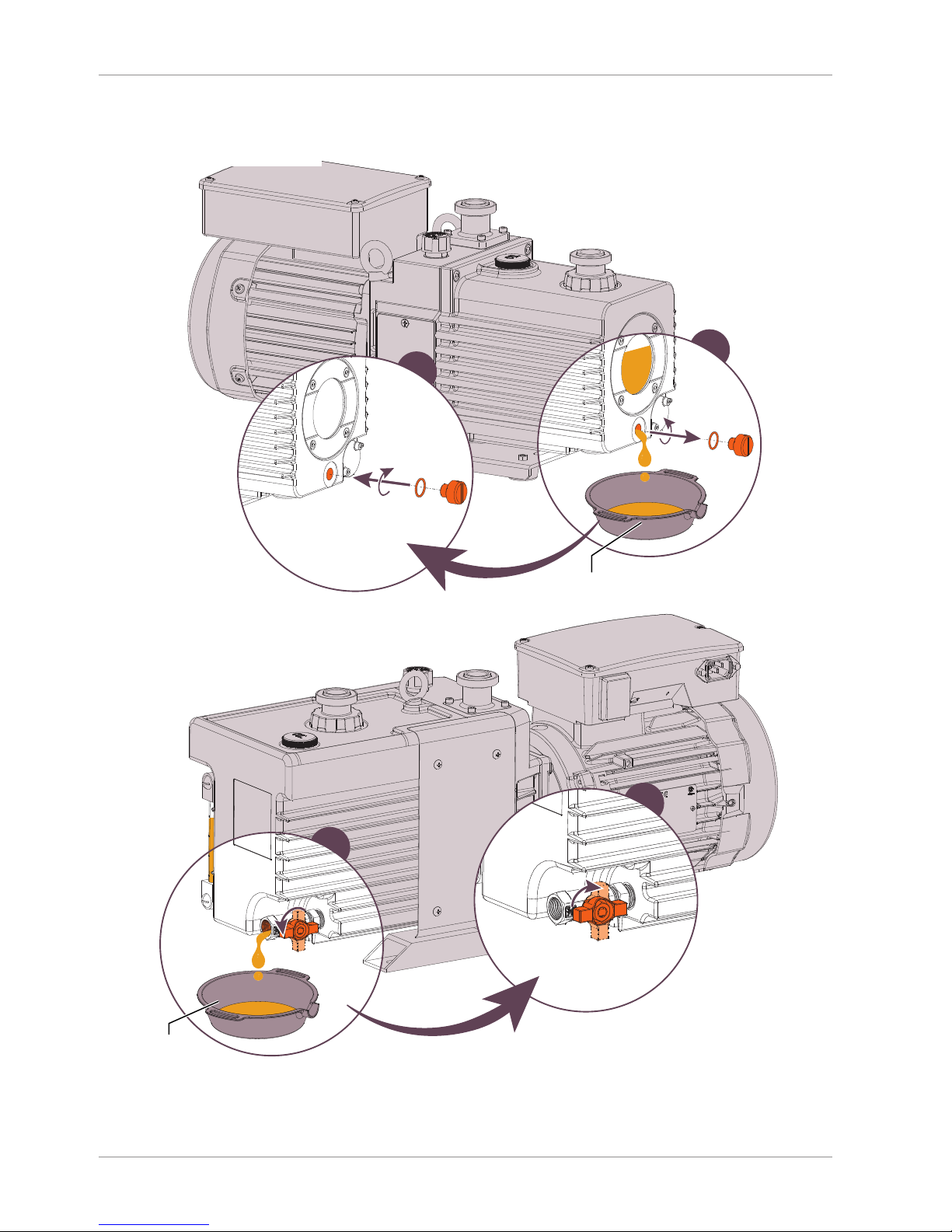
7.3 Oil Change
2
1
Drain pan
Oil draining for RH 0003-0015 B:
Check the o-ring
if it is correctly
seated in the groove
1
2
Drain pan
Oil draining for RH 0021 B:
Page 17
Maintenance | 7
0870169116_RH0003-0021B_-0002_IM_en 17 / 28
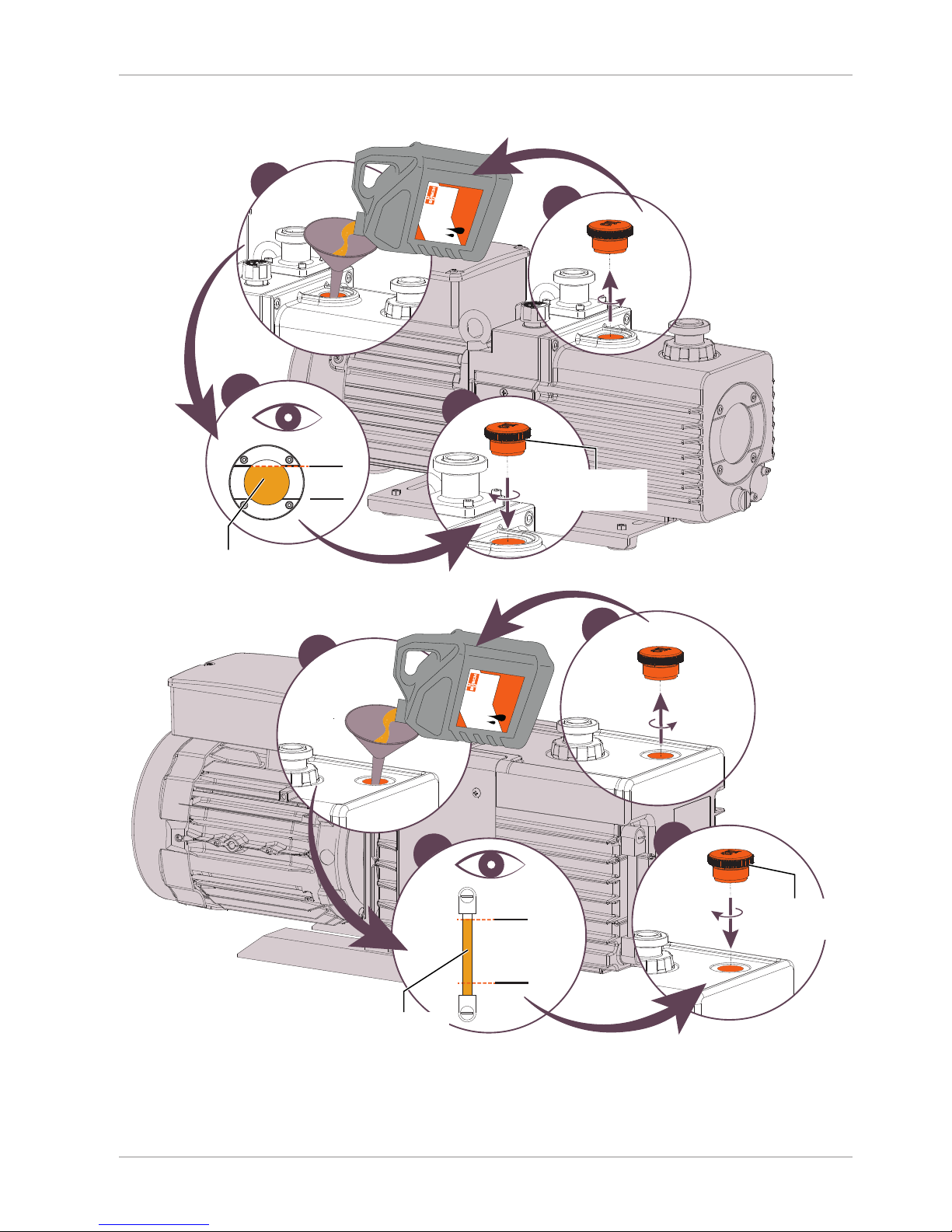
For oil type and oil capacity see Technical Data [}23] and Oil [}23].
1
4
MAX
MIN
3
2
2
Busch Oil
2
Check oil level
Oil filling for RH 0003-0015 B:
Check the o-ring
if it is correctly
seated in the groove
MAX
MIN
3
2
2
Busch Oil
1
4
2
Check oil level
Oil filling for RH 0021 B:
Check the o-ring
if it is correctly
seated in the groove
Page 18
8 | Overhaul
18 / 28 0870169116_RH0003-0021B_-0002_IM_en
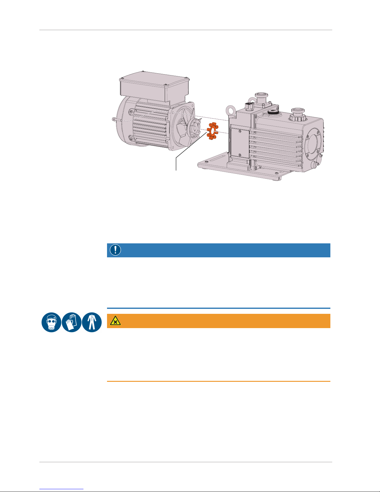
7.4 Coupling Maintenance
• Disassemble the machine according to the following illustration.
Coupling spider
• Check the coupling spider.
• Change it if necessary.
• Reassemble the machine.
8 Overhaul
NOTICE
Improper assembly.
Risk of premature failure!
Loss of efficiency!
• It is highly recommended that any dismantling of the machine that goes beyond anything that is described in this manual should be done through Busch.
WARNING
Machines contaminated with hazardous material.
Risk of poisoning!
Risk of infection!
If the machine is contaminated with hazardous material:
• Wear appropriate personal protective equipment.
In case of the machine having conveyed gas that was contaminated with foreign materials which are dangerous to health:
• Decontaminate the machine as good as possible and state the contamination
status in a ‘Declaration of Contamination’.
Busch will only accept machines that come with a complete filled in and legally binding
signed ‘Declaration of Contamination’.
(Form downloadable from www.buschvacuum.com)
Page 19

Decommissioning | 9
0870169116_RH0003-0021B_-0002_IM_en 19 / 28
9 Decommissioning
• Shut down the machine and lock against inadvertent start up.
• Vent the connected lines to atmospheric pressure.
• Disconnect all connections.
In case of storage is planned:
• See Storage [}7].
9.1 Dismantling and Disposal
• Drain the oil.
• Separate special waste from the machine.
• Dispose of special waste in compliance with applicable regulations.
• Dispose of the machine as scrap metal.
Page 20

10 | Spare Parts
20 / 28 0870169116_RH0003-0021B_-0002_IM_en
10 Spare Parts
NOTICE
Use of non-Busch genuine spare parts.
Risk of premature failure!
Loss of efficiency!
• The exclusive use of Busch genuine spare parts and consumables is recommended for
the proper function of the machine and for granting of warranty.
Spare parts kit Description Part no.
Minor maintenance kit
(RH0003 B)
Includes all the necessary parts for
minor maintenance.
0992 168 912
Minor and major maintenance kit
(RH0003 B)
Includes all the necessary parts for a
complete overhaul.
0992 168 912 +
0993 168 943
Minor maintenance kit
(RH0010 B)
Includes all the necessary parts for
minor maintenance.
0992 168 944
Minor and major maintenance kit
(RH0010 B)
Includes all the necessary parts for a
complete overhaul.
0992 168 944 +
0993 168 945
Minor maintenance kit
(RH0015 B)
Includes all the necessary parts for
minor maintenance.
0992 168 946
Minor and major maintenance kit
(RH0015 B)
Includes all the necessary parts for a
complete overhaul.
0992 168 946 +
0993 168 947
Minor maintenance kit
(RH0021 B)
Includes all the necessary parts for
minor maintenance.
0992 168 948
Minor and major maintenance kit
(RH0021 B)
Includes all the necessary parts for a
complete overhaul.
0992 168 948 +
0993 168 949
11 Accessories
Please contact your Busch representative for accessories list and references.
Page 21
Troubleshooting | 12
0870169116_RH0003-0021B_-0002_IM_en 21 / 28
12 Troubleshooting
DANGER
Live wires.
Risk of electrical shock.
• Electrical installation work must only be executed by qualified personnel.
CAUTION
Hot surface.
Risk of burns!
• Prior to any action requiring touching the machine, let the machine cool down first.
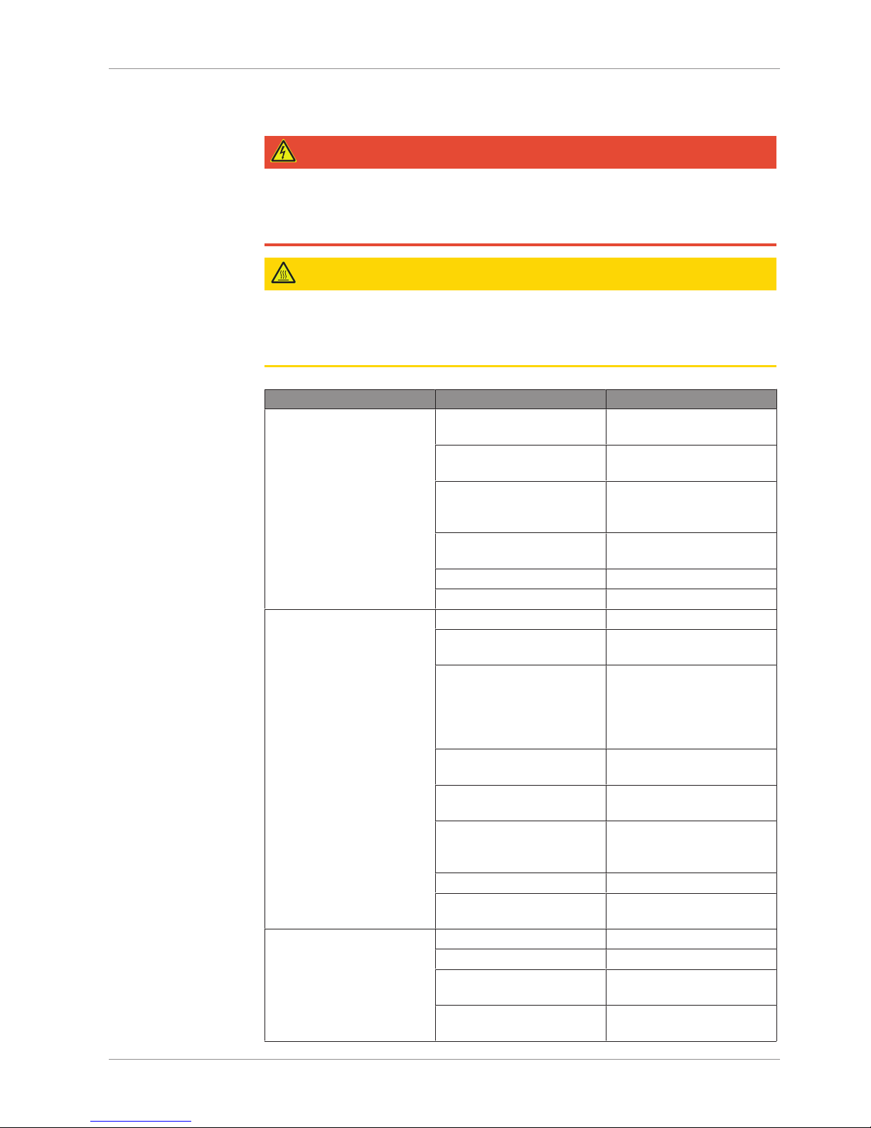
Problem Possible Cause Remedy
The machine does not start. Low ambient temperature. • Observe the permitted
ambient temperature.
The motor is not supplied
with the correct voltage.
• Check the power supply.
Solid foreign matter has
entered the machine.
• Remove the solid foreign
matter or repair the machine (contact Busch).
Internal parts are worn or
damaged
• Repair the machine (contact Busch).
The motor is defective. • Replace the motor.
The coupling is defective. • Replace the coupling.
The machine does not reach
the usual pressure on the
suction connection.
Oil level too low. • Top up oil.
The oil is not circulating. • Conduct an overhaul
(contact Busch).
Oil has deteriorated. • Perform a non load oper-
ation with vacuum valve
closed and gas ballast
valve open or replace the
oil.
The inlet screen is partially
clogged.
• Clean the inlet screen.
The inlet filter cartridge (optional) is partially clogged.
• Replace the inlet filter
cartridge.
Measurement method or
reading is false.
• Check gauge, check final
pressure without installation connected.
Leak in the system. • Repair leak.
Internal parts are worn or
damaged.
• Repair the machine (contact Busch).
The machine runs very noisily.
Worn coupling. • Replace the coupling.
Oil level too low. • Top up oil.
The oil is not circulating. • Conduct an overhaul
(contact Busch)
Internal parts are worn or
damaged.
• Repair the machine (contact Busch).
Page 22

12 | Troubleshooting
22 / 28 0870169116_RH0003-0021B_-0002_IM_en
The machine runs too hot.
(Pump surface rise up to
about 100 °C (212 °F)).
Continuous operation at too
high suction pressure.
• Reduce the suction pressure.
Insufficient cooling. • Remove dust and dirt
from the machine.
Ambient temperature too
high.
• Observe the permitted
ambient temperature.
Oil level too low. • Top up oil.
The oil is not circulating. • Conduct an overhaul
(contact Busch).
Oil has deteriorated. • Perform a non load oper-
ation with vacuum valve
closed and gas ballast
valve open or replace the
oil.
The machine fumes or expels oil droplets through the
gas discharge.
Oil level too high. • Drain the oil until it gets
the specified level.
Continuous operation is performed at high suction pressure.
• Install an oil mist separator.
Oil mist separator (optional)
is clogged.
• Replace the filter element.
Oil mist separator (optional)
is not assembled properly.
• Reassemble properly the
oil mist separator.
The oil is emulsified. The machine sucked in li-
quids or significant amounts
of vapour.
• Perform a non load operation with vacuum valve
closed and gas ballast
valve open or replace the
oil.
• Modify the operational
mode, )see Conveying
Condensable Vapours
[}14]).
For the solution of problems not mentioned in the troubleshooting chart contact your
Busch representative.
Page 23
Technical Data | 13
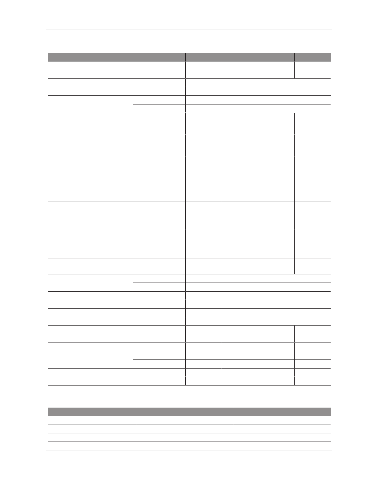
0870169116_RH0003-0021B_-0002_IM_en 23 / 28
13 Technical Data
RH 0003 B RH 0010 B RH 0015 B RH 0021 B
Pumping speed
(50Hz / 60Hz)
m³/h 2.4 / 2.9 8.1 / 9.7 12 / 14.4 16.9 / 20.2
cfm 1.4 / 1.7 4.8 / 5.7 7.1 / 8.5 9.9 / 11.9
Ultimate total pressure
(without gas ballast valve)
hPa (mbar) abs. 6.7 x 10
-3
Torr abs. 5 x 10
-3
Ultimate total pressure
(with gas ballast valve)
hPa (mbar) abs. 6.7 x 10
-2
Torr abs. 5 x 10
-2
Nominal motor rating
Single-phase motor
(50Hz / 60Hz)
kW 0.2 / 0.2 0.4 / 0.4 0.55 / 0.55 0.75 / 0.9
Nominal motor rating
Three-phase motor
(50Hz / 60Hz)
kW N/A 0.4 / 0.4 0.55 / 0.55 0.7 / 0.7
Nominal motor speed
Single-phase motor
(50Hz / 60Hz)
min
-1
1460 / 1760 1455 / 1750 1435 / 1730 1470 / 1770
Nominal motor speed
Three-phase motor
(50Hz / 60Hz)
min
-1
N/A 1460 / 1760 1460 / 1760 1460 / 1760
Noise level (EN ISO 2151)
with oil mist separator and singlephase motor
(50Hz / 60Hz)
dB(A) ≤ 52 / 53 ≤ 52 / 54 ≤ 54 / 56 ≤ 59 / 61
Noise level (EN ISO 2151)
with oil mist separator and threephase motor
(50Hz / 60Hz)
dB(A) N/A ≤ 49 / 52 ≤ 52 / 55 ≤ 59 / 63
Water vapour capacity
(with gas ballast valve)
g / h 5 37.8 40.4 73
Ambient temperature range °C 7 … 40
°F 45 … 104
Relative humidity at 30 °C (86 °F) 85%
Max. internal pressure hPa (mbar) gauge 300
Ambient pressure Atmospheric pressure
Cooling method Air cooled
Max. oil capacity l 0.8 1 1.1 1.1
qt 0.8 1.1 1.2 1.2
Oil type VSD 026 VMA 055 VMA 055 VMA 055
Weight with
Single-phase motor
kg 16 29 31 42
lbs 35 64 68 93
Weight with
Three-phase motor
kg N/A 26 29 34.5
lbs N/A 57 64 76
14 Oil
VSD 026 VMA 055
Viscosity at 40°C (104°F) 26 cSt (mm2/s) 55 cSt (mm2/s)
Part number 1L packaging 0831 169 419 0831 169 415
Part number 5L packaging N/A 0831 169 416
Page 24
15 | EU Declaration of Conformity
24 / 28 0870169116_RH0003-0021B_-0002_IM_en
15 EU Declaration of Conformity
This Declaration of Conformity and the CE-mark affixed to the nameplate are valid for the machine within the
Busch scope of delivery. This Declaration of Conformity is issued under the sole responsibility of the manufacturer.
When this machine is integrated into a superordinate machinery the manufacturer of the superordinate machinery
(this can be the operating company, too) must conduct the conformity assessment process for the superordinate
machine or plant, issue the Declaration of Conformity for it and affix the CE-mark.
The manufacturer Busch Produktions GmbH
Schauinslandstr. 1
DE-79689 Maulburg
declare that the machine(s): Zebra RH 0003 B; RH 0010 B; RH 0015 B; RH 0021 B
with a serial number 1679… to 1779…
has (have) been manufactured in accordance with the European Directives:
– ‘Machinery’ 2006/42/EC
– ‘RoHS’ 2011/65/EU, restriction of the use of certain hazardous substances in electrical
and electronic equipment
and following the standards.
Standard Title of the Standard
EN 1012-2:1996 + A1:2009 Compressors and vacuum pumps - Safety requirements - Part 2
EN ISO 2151:2008 Acoustics - Noise test code for compressors and vacuum pumps - Engineering
method (grade 2)
IEC/EN 61010-1:2010 Safety requirement for electrical equipment for measurement, control and
laboratory use - Part 1: General requirement
IEC/EN 60034-1:2010 Rotating electrical machines - Part 1: Rating and performance
EN 61000-6-2:2005 Electromagnetic compatibility (EMC) - Generic standards. Immunity for indus-
trial environments
EN 61000-6-4:2007 + A1:2011 Electromagnetic compatibility (EMC) - Generic standards. Emission standard
for industrial environments
EN ISO 13849-1:2015
(1)
Safety of machinery - Safety-related parts of control systems - Part 1: General
principles for design
Person authorised to compile the technical file: Andrej Riwe
Busch Produktions GmbH
Schauinslandstr. 1
DE-79689 Maulburg
Maulburg, 16.03.2016
Dr.-Ing Karl Busch, General director
(1)
In case control systems are integrated.
Page 25

Note
Page 26

Note
Page 27

Note
Page 28

Argentina
www.busch-vacuum.com.ar
Australia
www.busch.com.au
Austria
www.busch.at
Belgium
www.busch.be
Brazil
www.buschdobrasil.com.br
Canada
www.busch.ca
Chile
www.busch.cl
China
www.busch-china.com
Colombia
www.buschvacuum.co
Czech Republic
www.buschvacuum.cz
Denmark
www.busch.dk
Finland
www.busch.fi
France
www.busch.fr
Germany
www.busch.de
Hungary
www.buschvacuum.hu
India
www.buschindia.com
Ireland
www.busch.ie
Israel
www.busch.co.il
Italy
www.busch.it
Japan
www.busch.co.jp
Korea
www.busch.co.kr
Malaysia
www.busch.com.my
Mexico
www.busch.com.mx
Netherlands
www.busch.nl
New Zealand
www.busch.com.au
Norway
www.busch.no
Peru
www.busch.com.pe
Poland
www.busch.com.pl
Portugal
www.busch.pt
Russia
www.busch.ru
Singapore
www.busch.com.sg
South Africa
www.busch.co.za
Spain
www.buschiberica.es
Sweden
www.busch.se
Switzerland
www.busch.ch
Taiwan
www.busch.com.tw
Thailand
www.busch.co.th
Turkey
www.buschvacuum.com
United Arab Emirates
www.busch.ae
United Kingdom
www.busch.co.uk
USA
www.buschusa.com
www.buschvacuum.com
Busch Vacuum Pumps
and Systems
All over the World in Industry
0870169116/-0002_en / © Busch Produktions GmbH
 Loading...