


Manufacturer:
burster präzisionsmesstechnik gmbh & co kg
Talstraße 1 - 5 P.O.Box 1432
76593 Gernsbach 76587 Gernsbach
Germany Germany
Tel.: (049) 07224 / 6450
Fax.: (049) 07224 / 64588
E-Mail: info@burster.com
www.burster.com
© 2012 burster
präzisionsmesstechnik gmbh & co kg
All rights reserved
Software version V3.01
Valid from: 18.06.2012
TRANS CAL
Model 7280
972-007280EN-5070-061518

TRANS CAL
Model 7280
Page 2
Note:
All information in the present documentation was prepared and compiled with great care and reproduced
subject to effective control measures. No warranty is provided for freedom from errors. We reserve the
right to make technical changes. The present information as well as the corresponding technical data
can change without notice. Reproduction of any part of this documentation or its processing or revision
using electronic systems is prohibited without the manufacturer’s prior written approval.
Components, devices and measured value sensors made by burster praezisionsmesstechnik (hereinafter
referred to as „product“) are the results of targeted development and meticulous research. As of the date
of delivery, burster provides a warranty for the proper condition and functioning of these products covering
material and production defects for the period specied in the warranty document accompanying the
product. However, burster excludes guarantee or warranty obligations as well as any liability beyond that
for consequential damages caused by improper use of the product, in particular the implied warranty
of success in the market as well as the suitability of the product for a particular purpose. Furthermore,
burster assumes no liability for direct, indirect or incidental damages as well as consequential or other
damages arising from the provision and use of the present documentation.

Model 7280TRANS CAL
Page 3
EG-Konformitätserklärung
EC- Declaration of Conformity according to EN ISO/IEC 17050-1:2004
burster pr äzisionsmes stechnik gmbh & co kg . Talstr. 1-5 . D-76593 Gernsbach (Postfach 1432 D-76587 Gernsbach) Tel. 07224/645-0 . Fax 645-88
www.burster.de
.
www.burster.com . info@burster.de
Sitz der Gesellschaft: HRA 530170 Mannheim . Komplementär: burster präzisionsmesstechnik Verwaltungs-GmbH . Sitz der Gesellschaft: Gernsbach HRB 530130 Mannheim
Geschäftsführer: Matthias Bu rster
.
Prokurist: Edgar Miggler
.
UST-Identnr.: DE 144 005 098
.
Steuernr. : 39454/105 03
Dresdner Bank AG Rastatt Kto . 06 307 073 00 BLZ 662 800 53
.
Volksbank Baden-Ba den*Rastatt eG Kto. 30 2 082 00 BLZ 662 90 0 00
Name des Herstellers:
burster präzisionsmesstechnik gmbh & co kg
Manufacturer’s Name:
Adresse des Herstellers:
Talstr. 1-5
Manufacturer’s Address:
76593 Gernsbach, Germany
erklärt unter alleiniger Verantwortung, dass das gelieferte Produkt
declares under sole responsibility that the product as originally delivered
Produktname:
Prüfgerät für Kraft, Drehmoment, Weg und Druck TRANS CAL
Product Name: Test instrument for force, torque, length and pressure TRANS CAL
Modellnummer(n) (Typ):
7280
Models Number / Type:
Produktoptionen:
Diese Erklärung beinhaltet obengenannte Produkte mit allen Optionen
Options This declaration covers all options of the above product(s)
mit den folgenden europäischen Richtlinien übereinstimmt und entsprechend das CE-Zeichen trägt:
complies with the requirements of the following applicable European Directives, and carries the CE marking accordingly:
2006/95/EC Elektrische Betriebsmittel zur Verwendung innerhalb bestimmter Spannungsgrenzen
Low Voltage Electrical Equipment designed for use within certain voltage limits
2004/108/EC Elektromagnetische Verträglichkeit
EMC Electromagnetic Compatibility
Obengenannte Produkte entsprechen folgenden harmonisierten Normen:
Above named products conform with the following product standards:
Sicherheit:
IEC 61010-1:2001 / EN 61010-1:2001 Messkategorie 1 Schutzklasse III; *
Safety requirements: CAT 1
Safety class 3
* Netzteil Ladestation 7280-Z001
Docking station
Schutzklasse 2
Safety class 2
EMV Störaussendung:
IEC/CISPR 11:2003 + A1:2004 + A2:2006 / EN 55011:2007 + A2:2007
EMC Generic emission:
EMV Störfestigkeit:
IEC 61326-1:2005 / EN 61326-1:2006
Industrie Bereich
EMC Generic immunity:
Industrial environment
Ergänzende Informationen:
/ Additional Information:
Das Produkt wurde in einer typischen Konfiguration getestet. Um optimale Störfestigkeit zu erreichen ist das Gerät über
geschirmte Leitungen anzuschließen. Verwenden Sie nur den angegebenen Batterietyp.
The product was tested in a typical configuration. In order to reach optimal electromagnetic immunity the device has to be conducted
with shielded line.
Do not mix with different types of battery. Always use specified battery.
Diese Konformitätserklärung betrifft alle nach Ausstellungsdatum ausgelieferten Produkte:
This DoC applies to above-listed products placed on the EU market after:
Gernsbach 09.07.2008 i.V. Alfred Großmann
Datum / date Quality Manager
Dieses Dokument ist entsprechend EN ISO/IEC 1705 0-1:2004 Abs. 6.1g ohne Unterschrift gültig / According EN ISO/IEC 1705 0 this document is valid without a signa ture.

TRANS CAL
Model 7280
Page 4
Model 7280TRANS CAL
Page 5
Operating Instruction
Checking Device for Force, Torque, Displacement
and Pressure
Model 7280 (from V3.01)
from serial number: 20218
TRANS CAL
Model 7280
Page 6
Identication
Residual risks which can occur during the operation with the 7280 are pointed out with following
symbols in this instruction:
Warning:
A note which indicates a possible risk of serious or life-threatening injuries. The accident
prevention regulations of the government safety organizations must be considered.
Caution:
A note that indicates a possible risk of damage to the product, process, the human or
the environment
Note:
Additional information
Important / Tip:
Reference to more detailed technical information
Health and safety protection
To ensure that our products are safe and they pose no health hazard, the following points must be
considered:
1. All relevant sections of this manual must be read carefully before beginning with the operation.
2. All warning labels on packages and containers must be observed.
3. Installations, operation, maintenance and repair work must be carried out by suitably trained
personnel in accordance with the given instructions. If any of these instructions are not met, the
user of the product bears the full responsibility for all consequences occurring from this failure
to comply.
4. Before opening the device, it must be separated from any supply.
Qualied personnel
Qualied personnel are persons who are familiar wit the installation, operation and maintenance of the
7280 measuring amplier and also have the required qualications. The 7280 amplier is to be used
by qualied personnel according to the technical data in connection with the special safety rules and
regulations and use. In addition, the operation required for each individual application, legal and saftey
regulations. The 7280 measuring amplier shall only be used by qualied personnel according to the
specications and the following indicated safety regulations and rules. During the operation, the legal
and safety regulations, required for each individual application, must be considered in addition. This
also applies when using accessories.
Modication
The 7280 amplier may not be changed constructional or safety-related without our explicit
permission. burster präzisionsmesstechnik gmbh & co kg will not take responsibility for any
resulting damages. Repairs and modications of the printed boards are prohibited.

Model 7280TRANS CAL
Page 7
Contents
Page
1. General ............................................................................................................................9
1.1 Application ..........................................................................................................9
1.2 Description ..........................................................................................................9
2. Preparations for use ....................................................................................................11
2.1 Unpacking the device .......................................................................................11
2.2 Using the device for the rst time .....................................................................11
2.3 Mains operation ................................................................................................12
2.4 Safe and correct use .........................................................................................12
3. Controls and terminals ................................................................................................13
3.1 General ..............................................................................................................13
3.2 Program overview .............................................................................................13
3.3 Description of the key .......................................................................................14
3.4 Digital input .......................................................................................................15
3.5 Pin assignment ..................................................................................................16
4. Manual operation .........................................................................................................17
4.1 Menu description ..............................................................................................17
4.2 Measuring with 7280 .........................................................................................19
4.2.1 Negative zero output ........................................................................................ 19
4.2.2 Stored adjustment values ................................................................................ 19
4.3 Sensor parameters ............................................................................................20
4.4 ADJUST - adjustment menu .............................................................................20
4.5 Adjustment procedure.......................................................................................21
4.6 Operating and function principle of the data logger in 7280 amplier ..............23
4.7 Adjustments in the LOGG mode .......................................................................24
5. Remote ..........................................................................................................................25
5.1 Serial interface ..................................................................................................25
5.2 Read-out of current sensor parameters ............................................................26
5.3 Read-out complete status ................................................................................26
5.4 Read-out complete status ................................................................................27
5.5 Format of the serial interface output .................................................................29
5.6 Adjustments in the SCI mode ...........................................................................29
5.7 Transfer rate / specication RS232 (V.24) / USB ...............................................29
5.8 Link connection to USB ....................................................................................30
5.9 Measuring rate 1000/s and LOGG Mode 1 ms .................................................30
6. Technical data .............................................................................................................31
7. Programmer example ..................................................................................................33
8. Automatic OFF at battery / mains operation .............................................................37

TRANS CAL
Model 7280
Page 8
Contents
Seite
9. MISC ..........................................................................................................................37
9.1 Transportation ...................................................................................................37
9.2 Initiation and setup ............................................................................................37
9.3 Normal operation ..............................................................................................38
9.4 Maintenance and cleaning ................................................................................38
9.5 Disposal ............................................................................................................39

Model 7280TRANS CAL
Page 9
1.1 Application
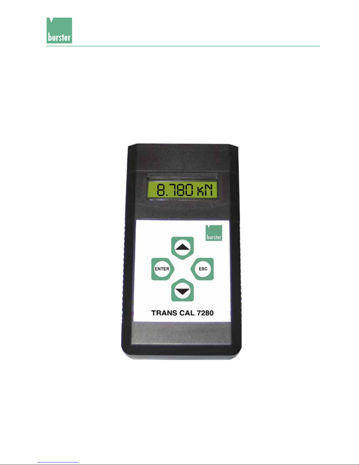
The portable digital indicator model 7280 is a universal checking device for instrumentation
examination mechanical components like press, equipment of torque and so on. The employment
takes place in the ranges quality assurance, start-up and process monitoring. By high measuring
rates very fast reactions to the measuring signals are possible. A min./max. memory makes
further areas of application possible for the equipment. A universally congurable data logger
can store measured values up to 15288. By the possibility 10 parameter sets to deposit, are
possible different calibration data such as sensor designation and physical units. Measured
values or logging values can be spent over RS232-/USB interface at a PC or a printer. So that
the measurement chain is traceable, a proprietary calibration certicate can be provided. The
traceability of the calibration exists over the used reference normal.
1. General
1.2 Description
The model 7280 is mobile by battery or accu, can be operated however also with an external
power pack. A high measuring accuracy paired with fast measuring rate, 16 bit A/D converter
and a microprocessor are ensured by the employment by highly precise ampliers.
The pocket model 7280 support sensors on strain gage basis and active sensors to 10 V /
20 mA. Indicated on the 14 mm high LED main display will the current measured value, on a
second display directly under it can for example the peak value be read off. With the function
tare can be away-tared an existing basis load. For a force measuring chain we recommend to
attach the tension and compression load cell model 8524 to the digital indicator. Depending
upon can be selected between measuring range of 500 N and 200 kN (divides into 9 stages).
The reference measuring chain is completely congures and calibrated.

TRANS CAL
Model 7280
Page 10

Model 7280TRANS CAL
Page 11
2. Preparation for use
2.1 Unpacking the device
The device weights approx. 0.5 kg and due to this it is packed shockproof. Unpack it accurately
and check the completeness of the delivery.
This normally includes: 1 TRANS CAL model 7280
1 copy of this manual
Verify accurately, that there is no damage on the device.
If here is a suspicion, contact the manufacturer within 72 hours.
Retain the packaging for examination by a representative of the manufacturer and/or the deliverer.
Only ship the TRANS CAL in original packaging or in a container providing the same degree
of protection.
2.2 Using the device for the rst time
Warning: The device must never be switched on if it shows signs of damage during
shipping.

TRANS CAL
Model 7280
Page 12
2.3 Mains operation
Mains operation:
A plug-in power supply with controlled 6 V DC must be employed with min 1.5 A. For discharged
batteries the charging current will be approx. 290 mA. In this way, the accumulators are also
loaded simultaneously, also in the case of switched-off 7280.
During continuous operation on the net, it is recommended to remove the accumulators. For fast
loading to 100 % of the accumulators, an external loader (e.g. Ansmann 4 - 6) is recommended.
Prior to mains operation (disposable-) batteries must be removed from the
device, as they would be destroyed by the charging process and thus lead
to equipment damage !
Accumulator operation:
Use 4 x NiMH Mignon-Accumulators of min. 1600 mAh and 1.2 V correctly poled.
Accumulator charge time:
The accumulator charge time at accumulator-capacity of 2.7 Ah is approx. 9 - 10 h. At discharged
accumulators, the constant charging rate is approx. 290 mA. Charged accumulators are
recognized by the Minus-Delta-Peak-Procedure (overload protection).
Battery operation:
Use 4 x Mignon/AA batteries with 1.5 V
Never use a power supply plug when batteries are inserted !
Voltage supply:
If the admissible battery voltage falls below, the display starts to blink.
Safe and correct use
Caution:
- Protect the device from moisture dew, rain, snow...
- Protect the device from direct solar irradiation
- Protect the device from dust and pollution
- Protect the device from high and/or excessive ambient temperature
- Protect the device from excessive vibration

Model 7280TRANS CAL
Page 13
3.1 General
The device can be operated via the keyboard or via the RS232-/USB interface. The following
describes operation of the keyboard in a brief overview.
3. Controls and Terminals
Brief overview for the operation
3.2 Operating overview
MINUS
ESC (7280 switch off)
ENTER (7280 switch on)
1 MEASURE
measure mode
ESC
SENSOR_
sensor selection
ESC
MEASURE
2 SYSTEM
systemparameter
PLUS
MINUS
ESC
ENTER
ENTER
ENTER
2.1 LANG
language
MINUS
PLUS
2.2 INFO
info
MINUS
PLUS
2.3 SCI
interface
MINUS
MINUS
ENTER/ESC
ESC
ESC
PLUS
2.4 RATE
MINUS
ESC
PLUS
2.5 PASS
password for adjust
MINUS
PLUS
2.6 LCD
LCD contrast
MINUS
ENTER/ESC
PLUS
2.7 LOGG
data logger
MINUS
ESC
PLUS
2.8 DATE
date and time
ESC
PLUS MINUS
deutsch
english
francais
espanol
ENTER
ENTER
PLUS MINUS
SW no.
firmware version
PLUS MINUS
BAUD
Baudrate
ENTER
SCI MODE
for measure mode
PLUS MINUS
RATE
measuring rate
ENTER
AVERAGE
average value
brighter
darker
ENTER
PLUS MINUS
LOGGMODE
LOGGSEND
LOGG DEL
ENTER
PLUS MINUS
DATE
TIME
ENTER
ENTER/ESC
ENTER/ESC
ENTER/ESC
ENTER/ESC
ENTER/ESC
ENTER/ESC
ENTER/ESC
3 ADJUST
adjustment menue
PLUS
ENTER
ENTER
SENSOR_
sensor selection
ESC
ESC
3.01
ENTER
PLUS MINUS
2400, 4800, 9600
19200, 38400
115200
ENTER
PLUS MINUS
SCI off
Hand (ENTER)
AUTO
TRIGGER
ENTER
PLUS MINUS
mess / sec
1/10/100/1000
ENTER
PLUS MINUS
1, 2 4, 8, 16, 32
ENTER
PLUS MINUS
LOGG off
HAND
AUTO
DIAGRAM
WINDOW
ENTER
17.04.2012
14:30:00
ENTER
PLUS MINUS
POINT_DIS
100 % range, decpnt
UNIT
physic. unit
ADJUST
adjustment menue
DESIGN
sensor name
ESC
ACT wCON
aktive with control
ENTER
AKT nCON
aktive without control
MINUS
PLUS
MINUS
PAS wCON
passive with control
PAS nCON
passive without control
PLUS
PLUS
CURRENT
0-20 / 4-20 mA
PLUS
MINUS
ENTER/ESC
ENTER
ENTER/ESC
ENTER
ENTER/ESC
ENTER
ENTER/ESC
ENTER
ENTER/ESC
ENTER
Sensors
with control:
self adjustment
Sensors
without control:
sensitivity
or
adjustment
with
100 % load
Measure settings System settings
USB
RS232
ENTER/ESC
ENTER
INTERFAC
interface mode
PLUS MINUS
PLUS MINUS
PLUS MINUS
10 ms
100 ms
1 sec
10 sec
1 min
10 min
1 h
ENTER
ESC
ENTER
PLUS MINUS
1 ms
10 ms
100 ms
1 sec
10 sec
1 min
10 min
1 h
ENTER
ENTER
Adjustment settings
You must first enter the password (9373) under the menu iterm 2.5 to activate the adjustment settings.

TRANS CAL
Model 7280
Page 14
3.3 Description of the keys
Example:
In 7280 switch on
- The 7280 is switched on, when ENTER button is pressed.
Time and data
- control or correct time and date in SYSTEM menu
Edit language
-
Change in menu to 2 SYSTEM – 2.1 LANG. When ENTER button is pressed,
7280 is in selection mode. With the buttons PLUS and MINUS the language can
be selected. With ENTER the selected language will be saved. With ESC the
selected language will be discarded.
Edit time
-
Change in menu to 2 SYSTEM – 2.8 DATE. When ENTER button is pressed
TIME will appear on LCD. Press ENTER and you can edit the time. With PLUS
and MINUS button the hours can be adjusted. After ENTER the minutes can be
adjusted with PLUS and MINUS button. With ENTER the selected time will be
saved. With ESC the selected time will be discarded.
Chance into the measure mode
- From menu 1 MEASUR by pressing ENTER the list of all sensors is called up. By the keys
PLUS and/or. MINUS a sensor parameter set is being chosen, then. By pressing ENTER
the 7280 is being adjusted to this sensor parameter set. By pressing ESC it is possible
to switch back to menu 1 MEASUR from any mode.

Model 7280TRANS CAL
Page 15
Change measuring rate by measuring mode
- The measuring can be exited by pressing key ESC. After pressing key ESC again, the
7280 will return to menu 1 MEASUR. From there the menu 2 SYSTEM – 2.4 Rate can be
called up.Select entry RATE by key PLUS and/or MINUS. By pressing key ENTER the
set measuring rate is being displayed, rst.By key PLUS and/or MINUS a new measur-
ing rate can be set now. By ENTER the new measuring rate will be taken over, by ESC
the new measuring rate will be discarded.
Switch off 7280
- 7280 is switched off, when ESC button is pressed >3 seconds.
3.4 Digital input
The device has a voltaic isolated control input: Trigger. This input can be controlled by e.g. a
PLC, a remote switch, a foot switch etc. As 100 % control signal, following voltage levels must
be applied at the phone jack for the respective logic state:
Logic state Low level High level
Voltage level 0 V ... 2 V 3.5 V ... 27 V
State inactive active
Trigger input
- Depending on adjustment, data can be logged or interface data can be issued.
This input has a high sampling rate, thus very short pulses are detected.
Key assignment:
Key Programming mode
▲ Scroll up
▼ Scroll down
ENTER Conrmation, one step forward in the menu
ESC Reject, one step back in the menu
TRANS CAL
Model 7280
Page 16
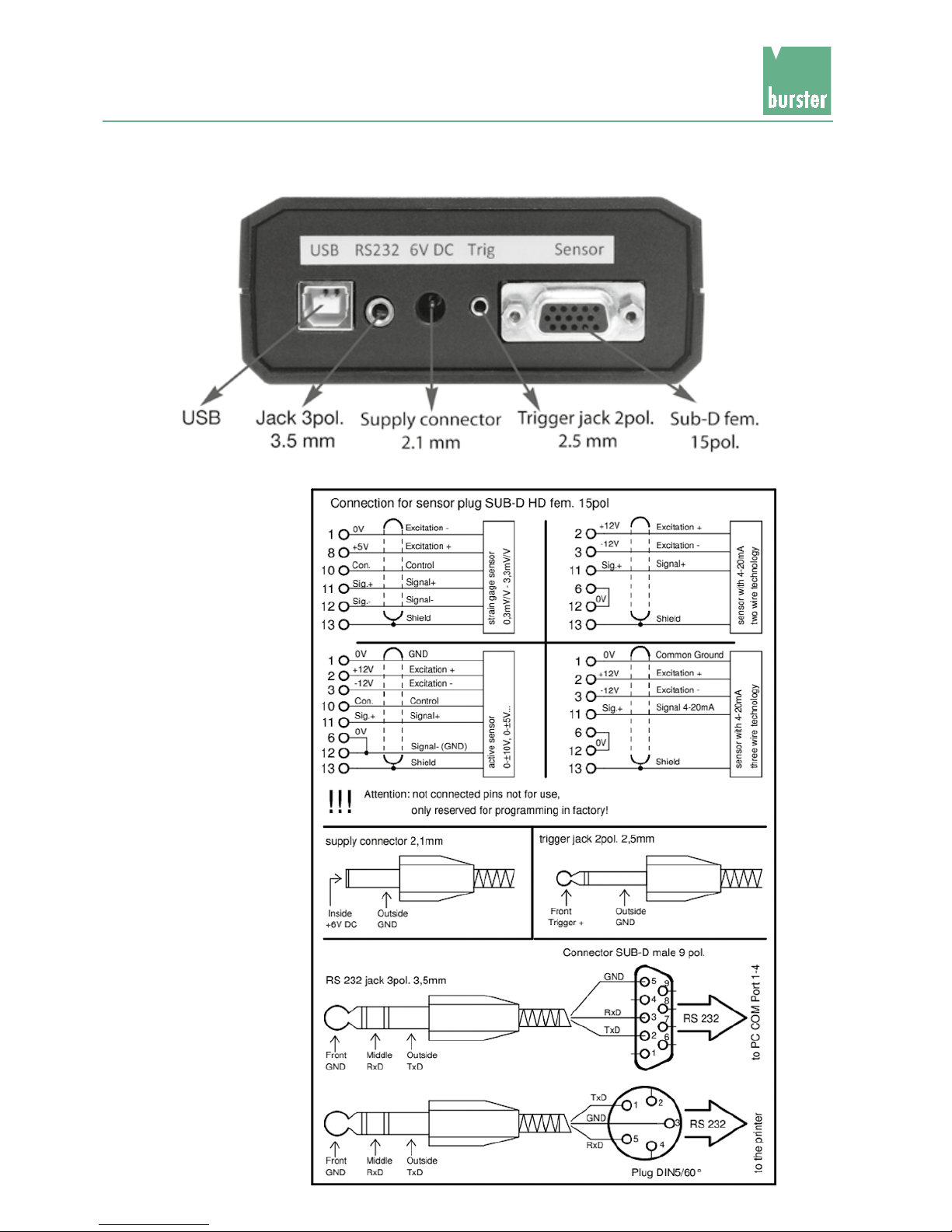
3.5 Pin assignment
Pin assignment of
the sensors

Model 7280TRANS CAL
Page 17
4. Manual Operation
4.1 Menu description
1 MEASURE Measuring mode
SENSOR__ Sensor selection for measuring mode, sensor 0 - 9
Selection of the sensor parameter set of the measurement. The
sensor parameter set must comply with the connected sensor.
2 SYSTEM All system parameters are stored in this menu column.
2.1 LANG Language adjustment
The menu language is available in English, German, French and
Spanish.
2.2 INFO Information query was factory-congured and is not modiable.
SW no. Firmware version
2.3 SCI Interface conguration
BAUD Baud rate adjustment; it must comply with the receiver (PC or printer).
SCI MODE The interface conguration only refers to the measuring mode, not
the log mode!
SCI off Interface switched off
HAND When pressing ENTER in the measuring mode, a measured value
is displayed.
AUTO1 Interval time, adjustable from 10 ms to 1 h (at high measuring rate
only possible with the highest baud rate).
TRIGGER At rising edge on the trigger input, in measuring mode a measured
value is displayed.
INTERFAC Interface selection
USB USB interface is activated
RS232 RS232 interface is activated
2.4 RATE Measuring rate1 and average value
RATE Measuring rate adjustment, selectable from 1/s to 1000/s. For fast
procedures (screw joint, insert press...) always select a fast measur-
ing rate, e.g. 1000/s, for very slow procedures select a small rate,
e.g. 1/s.
AVERAGE Average determination, the numbers indicate the average determina-
tion by the amount of measurements. Applicable for e.g. vibrations,
control oscillations...
2.5 PASS Password query
RATE Entering password 9373 allows to change to menu 3 ADJUST. Here,
the sensor parameters can be changed.
2.6 LCD LCD contrast adjustment
If the LCD becomes unreadable by external inuences, e.g. solar
radiation, heat or cold, the LCD contrast can be changed by press-
ing key ▲ or ▼.
1
If the SCI → AUTO interval time is shorter than the adjusted measuring rate, the same measured value
will be issued on the interface until a new value is entered.

TRANS CAL
Model 7280
Page 18
2.7 LOGG Data logger adjustments
LOGGMODE Data logger conguration
LOGG off Off-switch for logger operation, measuring mode possible, only.
Hand With each keystroke on ENTER a log value is accepted.
AUTO Adjustment of the measurement intervals for the automatic measured
value storing.
DIAGRAM With each rising edge of the trigger signal, a log value is accepted.
WINDOW The window operation is started by a rising trigger edge and can be
nished only by a falling edge. During this time, measured values
are stored in 1 ms raster in the data logger.
LOGGSEND Log values are issued through the interface, press ENTER twice.
LOGGDEL Log values are deleted after a safety query. Before deleting, please
assure that the data was received.
2.8 DATE Data and time adjustment
DATE Date
TIME Time
3 ADJUST Adjustmenu
This menu is active only, if the password has been entered in menu
mode 2.5 PASS. For the adjustment, the sensor must be connected
to the sensor socket.
Sensor__ Sensor number or the name of the sensor which shall be adjusted.
POINTDIS Final measurement value of the sensor with decimal indication e.g.
1000; 100.0; 10.00; 1,000. The numerical values are variable, 4 digits
are available. Change to menu mode POINTSDIS. After pressing
ENTER, the nal measurement value of the sensor can be entered.
With keys ▲ and/or ▼ the rst digit can be edited, go to the next
gure by pressing ENTER. When all 4 digits are edited, the decimal
point gets shifted by keys ▲ and/or ▼. Press ENTER to complete
the entry, the nal value will then be stored in the 7280 measuring
amplier.
UNIT Entry of the physical unit e.g. kg, Ncm, t, gr, kN, Nm, bar...
ADJUST Sensor type selection (active with 100 % control signal, active without
100 % control signal, passive with 100 % control signal, passive
without 100 % control signal, 4-20 mA.
DESIG Name of the sensor e.g. sensor 1, 2, 3, DR-2112, silo, tank, mixer,
scale 1, motor, test 1...

Model 7280TRANS CAL
Page 19
4.2 Measuring with 7280
Measuring with 7280
selected sensor is: Force sensor with meas. range 200 kN
Sens.: 2 mV/V
Designation e.g.: Squeezer
Parameter set: Sensor no.: 3
Option: 100 % Cal. control
In order to be able to now measure with this sensor, the sensor „SQUEEZER“ is selected in
the measuring mode. During a measurement, a minimum and maximum value buffer can be
called up with the arrow keys, the in each case displayed minimum or maximum value can
be deleted with ENTER.
If the measured value should be sent through an interface to a pc or printer, the baud rate
must be adjusted to the receiver and the operating mode must be chosen in the case of SCI-
MODE. For example: HAND, a measured value with time is displayed during every keystroke
on ENTER while measuring.
Should data be logged, adjust operating mode in the logger mode, e.g. choose AUTO and
range time e.g. 10 sec and enter the measuring mode. A measured value with time is now stored
every 10 sec. In the mode LOGGSEND, these data then can be sent through the interface.
ENTER
4.2.1 Negative zero output
With no sensor parameter set, a negative zero output from the sensor can be entered (manually by hand). A negative zero output can only read in directly from the sensor with teach-in
(function adjustment).
4.2.2 Stored adjustment values
The stored adjustment value are not displayed. This will only stored inside the device and can´t
be changed manually.
Key assignment:
Key Measuring mode
▲ Press = TARA
▼ MEASURING --- MIN --- MAX --- MEASURING
at MEASURING: send data
at LOGG: store measured value
at MIN: delete MIN
at MAX: delete MAX
ESC Back to menu / Press 3 sec. Press = Off

TRANS CAL
Model 7280
Page 20
4.3 Sensor parameters
After the password (9373) input in the system, the sensor can be applied in the calibrating menu.
Following parameters are available:
Sensor_ Sensor no 3 Sensor 0 - 9 possible
POINTDIS 200.0 Adjust meas. range and decimal point (max. 9999)
UNIT _kN 1 – 3 digit unit possible
DESIGN Squeezer up to 8 digit name (or numbers) freely optional
ADJUST PAS_nCON Select passive without cal. control
0 % LOAD Relieve sensor 0% value of sensor, indication 0 is assigned
100 % CON Autom. calibration 100 % value of sensor will be assigned to
indication 200 kN
SAVE ENTER or ESC Conrm or reject
4.4 ADJUST Adjustment menu
3 ADJUST Adjustment menu
This menu is active only, if the password has been entered in menu
mode 2.5 PASS. For the adjustment, the sensor must be connected
to the sensor socket.
Sensor_ Sensor number or the name of the sensor which shall be adjusted.
POINTDIS Final measurement value of the sensor with decimal indication e.g.
1000; 100,0; 10.00; 1.000; ...
The numerical values are variable, 4 digits are available. Change to
menu mode POINTDIS. After pressing ENTER, the nal measurement value of the sensor can be entered. With keys ▲ and/or▼ the
rst digit can be edited, go to the next gure by pressing ENTER.
When all 4 digits are edited, the decimal point gets shifted by keys
▲ and/or▼. Press ENTER to complete the entry, the nal value will
then be stored in the 7280 measuring amplier.

Model 7280TRANS CAL
Page 21
UNIT Entry of the physical unit, e.g. Kg, Ncm, t, kN, Nm, bar ...
DESIG Name of the sensor, e.g. 1, 2, 3, DR 2112, silo, tank, mixer, scale1,
motor, test1...
ADJUST Sensor type selection:
ACTIVE without control signal, for transmitter 0-10 V
CURRENT for transmitter 4-20 mA.
PASSIVE without control signal
, for strain gauge (load) sensors
4.5 Adjustment procedure
ACT nCON Active sensor without 100 % control signal
with following adjustment possibilities:
- adjust 0 % load and 100 % load
- adjust 0 % load and enter hub
(100 % load in V - 0 % load in V)
- enter 0 % load in V and the hub
(100 % load in V - 0 % load in V)
Select between 0 % load or nominal value by pressing ▲ or ▼
0 % LOAD unload sensor
or NOMVALUE input of the nominal value in V
Select between load or nominal value by pressing ▲ or ▼
100 % LOAD Adjustment by 100 % load (apply nominal load)
or NOMVALUE input of the nominal value in V
SAVE Query for takeover of the adjusted data
PAS nCON Passive Sensor without 100 % control signal
with following adjustment possibilities:
- adjust 0 % load and 100 % load
- adjust 0 % load and enter 100 % load in mV/V
- enter 0 % load in mV/V and 100 % load in mV/V
Select between load or nominal value by pressing ▲ or ▼
0 % LOAD unload sensor.
or NOMVALUE input of the nominal value in mV/V
Select between 100 % load or nominal value by pressing ▲ or ▼
100 % LOAD adjustment by load (apply nominal load).
or NOMVALUE input of the nominal in mV/V
SAVE Query for takeover of the adjusted data

TRANS CAL
Model 7280
Page 22
Adjustment procedure
CURRENT Sensor with 4 ... 20 mA
with following adjustment possibilities:
- adjust 0 % load and 100 % load
- adjust 0 % load and 100 % load in mA
- enter 0 % load in mA and 100 % load in mA
Select between 0 % load or nominal value by pressing ▲ or ▼
0 % LOAD unload sensor
or NOMVALUE input of the nominal value in mA (xed value 4-20 mA)
Select between 100 % load or nominal value by pressing ▲ or ▼
100 % LOAD adjustment by 100 % load (apply nominal load / nominal torque)
or NOMVALUE input of the nominal value in mA
SAVE Query for takeover of the adjusted data
If a sensor cannot be selected and/or does not change to the measuring
mode, there was a false adjustment for this sensor / parameter set. → Readjustment

Model 7280TRANS CAL
Page 23
4.6 Operating and function principle of the
date logger in 7280 measuring amplier
The data logger can, if the 7280 measuring amplier is not in the measuring mode, be read by
the menu option 2.7 LOGG - SENDING or by the command „A“ via the interface. Outside of the
measuring mode the data logger is deleted only by the menu option 2.7 LOGG - DELETION.
If the 7280 measuring amplier is in the measuring mode, the data logger can be read with the
command „A“ and be deleted with the command „B“.
If the measuring mode is being switched on from the menu option 1 MEASURING-sensor
selection, the starting time of the measurement, the current sensor designation, the nal value
of the measuring range, the adjusted measuring rate and the logger mode (e.g.: AUTO 1 ms)
are saved in the logger.
NOTE: All previous measured values are deleted here!
With the read-out of the data logger via the serial interface different adjustments of the 7280
are sent.
a.) letter head
b.) starting time of the measurement
c.) sensor designation
d.) display nal value
e.) adjusted measuring rate
f.) adjusted logger mode
g.) thereafter the measured values
In the HAND MODE the measured values are always logged with the time. With the data in the
AUTOMODE the measured value is logged. A time can be assigned to each measured value
by the indicated starting time.
Since in GRAPHS and in the WINDOW MODE trigger events smaller than 1 sec can occur, an
additional time log is not possible.

TRANS CAL
Model 7280
Page 24
4.7 Adjustments in the LOGG mode
LOGG OUT Here the data logger is switched off. the logg mode in the measur-
ing mode is switched to “LOGG OUT” as soon as the entire data
logger has been edited.
HAND In this mode a measured value is written into the data logger when
the enter key was pressed at the 7280. By an additional logg of time,
there is a assignment for each measured value.
AUTO In this mode in the adjusted delay a measured value is written into
the data logger. By the stored starting time there is a time assignment for each measured value.
GRAPH In this mode at a trigger event a measured value is written into the
logger. Since the trigger pulses occur in 10 ms raster, an additional
logg of the time is not possible. The ank of the trigger pulse must
stand on HIGH for 4 ms at last. Afterwards on LOW for at least 6 ms.
WINDOW This mode reacts to in increasing and/or decreasing anks. At an
increasing ank the logging of the measured values is started. From
now on the measured values are written in the data logger with 1
ms raster. A decreasing ank ends the recording.
Memory depth of data logger - see chapter 5.1
Trigger Signal
Read values

Model 7280TRANS CAL
Page 25
5. Remote
5.1 Serial interface
For the serial data transmission the 7280 measuring amplier uses a RS232 or
an USB interface. The PC manages the USB interface as a virtual COM port.
For the use of the USB interface, must have a windows operating system (2k,
XP, Vista, 7) and the burster präzsionsmesstechnik gmbh & co kg USB driver
must be installed (see chapter 3 - further documentation). After the driver
installation, the virtual COM port can be used as described below.
Transfer rate / specication RS232 (V.24) / USB
Parity: none
Number of data bits:
8 (1 Byte) 8N1
Stop bit: 1
Baud rate adjustable (2400, 4800, 9600, 19200, 38400, 115200 Baud)
In the USB mode, the baud rate in the 7280 measuring amplier and the
connected device must match.
Protocol overview
Via the serial interface, the 7280 measuring amplier can issue the measured values individually
or automatically. The commands can be send to the 7280 measuring amplier via a termal
program or a PLC.
Following commands are available:
Command overview
ASCII HEX Description in measuring not in measuring
mode mode
k 0x6B ENTER
I 0x6C ▲
m 0x6D ▼
n 0x6E ESC
A 0x41 Read-out data logger
C 0x43 Read-out current sensor parameters
D 0x44 Read-out status
E 0x45 Read-out complete status
g 0x67 Change protocol setup
0 0x30 Continuous measured value query (signed integer)
1 0x31 Query of max. value (signed integer)
2 0x32 Query of min. value (signed integer)
3 0x33 Tare of display
4 0x34 Reset max. value
5 0x35 Reset min. value
6 0x36 Actuate 100 % 100 % control signal -
for sensors with 100 % control resistance
7 0x37 Switch-off 100 % 100 % control signal
for sensors with 100 % control resistance
B 0x42 Delete data logger
a 0x61 Write time
b 0x62 Read-out time
c 0x63 Write company head
e 0x65 Write all sensor parameters (not supported yet)
f 0x66 Read-all sensor parameters (not supported yet)
In Menu 3: ADJUST → UNIT and ADJUST → DESIG the
adjustments can be changed by the commands “I” and “m”
}

TRANS CAL
Model 7280
Page 26
5.2 Read-out of current sensor parameters
Sensor designation 8 Byte ASCII
Final displayed value 2 Byte compressed BCD-gure
Unit 3 Byte ASCII
Sensor type and digit 1 Byte 0xAB: A ... Sensor type, B ... digit (binary coded)
Sensor type:
0xXXXX XXXX
||||
0000 ... active with 100% 100% control signal adjust 0% load and 100% load
0001 ... active without 100% 100% control signal adjust 0% load and 100% load
0010 ... active without 100% 100% control signal adjust 0% load and 100% load V
0011 ... active without 100% 100% control signal adjust 0% load V and 100% load V
0100 ... passive with 100% 100% control signal adjust 0% load and 100% load
0101 ... passive without 100% 100% control signal adjust 0% load and 100% load
0110 ... passive without 100% 100% control signal adjust 0% load V and 100% load mV
0111 ... passive without 100% 100% control signal adjust 0% load mV and 100% load mV/V
1000 ... current adjust 0% load and 100% load
1001 ... current adjust 0% load and 100% load mA
1010 ... current adjust 0% load mA and 100% load mA
Digit:
0xXXXX XXXX
||||
|000 ... _5000___
|001 ... _5,000__
|010 ... _50,00__
|011 ... _500,0__
|100 ... 5,000___
0%load 2 Byte HEX value (MSB/LSB)
100% load 2 Byte HEX value (MSB/LSB)
5.3 Read-out complete status
Status 2 Byte general error condition of the 7280 measuring amplier

Model 7280TRANS CAL
Page 27
5.4 Read-out complete status
Status 2 Byte General error condition of the 7280 measuring amplier
Meas. rate 1 Byte 0x01 ... 1000/sec
0x02 ... 100/sec
0x03 ... 10/sec
0x04 ... 1/sec
Average value 1 Byte 0x01 ... x/1
0x02 ... x/2
0x04 ... x/4
0x08 ... x/8
0x10 ... x/16
0x20 ... x/32
SCI_MODE 1 Byte 0x00 ... interface is off mode
0x04 ... hand mode
0x08 ... automatic mode
0x0C ... trigger mode
SCI_MODE_DELAY 1 Byte 0x02 ...10 ms
0x03 ... 100 ms
0x04 ... 1 s
0x05 ... 10 s
0x06 ... 1 min
0x07 ... 10 min
0x08 ... 1 h
LOGGMODE 1 Byte 0x00 ... logger is off mode
0x04 ... hand mode
0x08 ... automatic mode
0x0C ... DIAGRAM mode
0x10 ... windows mode
LOGGMODE_DELAY 1Byte 0x01 ... 1 ms
0x02 ... 10 ms
0x03 ... 100 ms
0x04 ... 1 s
0x05 ... 10 s
0x06 ... 1 min
0x07 ... 10 min
0x08 ... 1 h
Language 1 Byte 0x00 ... GERMAN
0x02 ... ENGLISH
0x04 ... FRENCH
0x06 ... SPANISH
Protocol status 1 Byte 0xXXXX XXXX (binary coded)
|||| ||||
|||||||1...donotsendnalcharacter
|||| ||1 ... send CR/LF
|||| |1 ... send CR
|||| 1 ... send LF
Write time:
Write time is identical to data block receipt of time. However, the data block for writing is protected with a check sum and the referring weighted check sum.
Read time:
With following read-out:
DAY.MONTH.YEAR
2xSpace
HOURS:MINUTES:SECONDS

TRANS CAL
Model 7280
Page 28
Write company head:
The entry ends either if 256 characters are received or if the character ETX (0x03) Strg-C is
contained in the character string.
Read company head:
By this command, the company head, which is stored in the 7280 measuring amplier, is read-out.
Write all parameters:
The writing data block of all sensor parameters is identical with the receiving data block for
reading all parameters. However, for the writing of the sensor parameters a check sum and
the referring weighted check sum is required.
Read all parameters:
The read-out of all parameters from sensor 1 to sensor 10 occurs in following sequence:
Sensor designation
Final displayed value
Unit
Sensor type (adjustment type) / decimal point
Adjustment values 0 % load, 100 % load with 2 Bytes each
See command “read current sensor parameters”.
Change protocol setup:
Protocol status 1 Byte
0xXXXX XXXX (binary coded)
|||| ||||
|||||||1 ...donotsendnalcharacter
|||| ||1 ... send CR/LF
|||| |1 ... send CR
|||| 1 ... send LF
Calculation of the check sum (CS) and the weighted check sum (gewCS):
The calculation occurs via all parameter bytes (without the command byte). At the CS all bytes
are added (overows are not considered here). For the calculation of the gewCS, the CS is
added to the gewCS. At overow, the gewCS is incremented by 1.

Model 7280TRANS CAL
Page 29
5.5 Format of the serial interface output
Operation via serial interface/USB
Output format in SCI mode:
HAND Sign, value, unit, time and CRLF
AUTO 10 ms value (signed integer) and CRLF
100 ms value (signed integer) and CRLF
1 s Sign, value, unit, time and CRLF
10 s Sign, value, unit, time and CRLF
1 min Sign, value, unit, time and CRLF
10 min Sign, value, unit, time and CRLF
1 h Sign, value, unit, time and CRLF
TRIGGER value (signed integer) and CRLF
Output format in LOGG mode:
HAND Sign, measured value, unit, time and CRLF
AUTO Sign, measured value, unit and CRLF
DIAGRAM Sign, measured value, unit and CRLF
WINDOW Sign, measured value, unit and CRLF
5.6 Adjustments in the SCI mode
SCI off: With this adjustment, measured values transfer from the 7280 measuring
amplier is disabled, but the 7280 measuring amplier can be controlled
via the 7280 commands.
HAND: In this mode a measured value is issued via the serial interface when
ENTER is pressed at the 7280 measuring amplier.
AUTO: In this mode a measured value is issued via the serial interface in the
adjusted delay.
TRIGGER: At a trigger event in this mode, a measured value is issued via the
serial interface. The trigger pulses can occur in 10 ms raster. The ank of
the trigger pulse must be on HIGH for at least 4 ms. Then it must be
on LOW for at least 6 ms.
5.7 Transfer rate / specication RS232 (V.24) / USB
Parity: none
Number of data bits: 8 (1 Byte)
Stop bit: 1
Baud rate: adjustable (2400; 4800; 9600; 19200; 38400; 115200
In the USB mode, the baud rate in the 7280 measuring amplier
and in the connected device must match.

TRANS CAL
Model 7280
Page 30
5.8 Link connection to USB
To establish a connection between 7280 an PC, the user can install the USB driver on his PC.
7280 in 2.3 SCI/INTERFACE choose “USB” as the interface and in 2.3 SCI/BAUD set the desired
BAUD rate. Then connect the 7280 to your PC and start the software. Under the menu point
settings/interface select the COM port with the name “XXXXX USB Sensor” and select in the
same menu the same BAUD rate as in 7280. After that, the communication is established and
can be used exactly as directed by the RS232 interface.
5.9
Measuring rate 1000/s and LOGG Mode 1 ms
During a measurement at a rate of 1000/s and active LOGGING mode with 1 ms can read via
the PC software in the section Data Logger no readings. This is because, that the measurement
values are written 10 x faster in the devices internal memory, as they can be output via interface.

Model 7280TRANS CAL
Page 31
6. Technical Data
Accuracy: 0.1 % F.S. ± 1 digit
Measuring rate: 1 / 10 / 100 / 1000 sec.
Average values: x/1, x/2, x/4, x/8, x/16, x/32
Display counts: ± 9.999 + 3 dig. unit
Zero point alignment: automatic/manual
Sensor selection for measurement mode: 10
Data logger mode: window, diagram, manual, auto
Memory values: max. 15288
Bridge restance of the strain gauges: 350 ... 2000 Ω
Sensitivity, passive: ± 3.3 mV/V
Sensitivity, active: ± 10 V
Input resistance: approx. 100 kΩ
Sensitivity, current: 0/4 ... 20 mA an at 75 Ω
Connection technology: 2 or 3 wire
Voltage supply passive/active: 5 V / 20 mA ± 12 V / over 100 mA
± 12 V altogether max. 120 mA
Working time with 50 % circle duration with accus:
passive sensors > 20 h
active sensors > 8 h
Nominal temperature range: + 15 °C ... + 35 °C
Range of operating temperature: + 5 °C ... + 45 °C
Storage temperature range: - 10 °C ... + 70 °C
Dimensions (D x W x H): 200 x 100 x 40 [mm]
Protection class: IP40

TRANS CAL
Model 7280
Page 32

Model 7280TRANS CAL
Page 33
Given : Load cell model 8524-6050 strain gauge 350 Ω
Range: 50 kN
Output signal : 1.5016 mV/V
Zero output without tting parts: 0.0020 mV/V
Adjustment procedure
The 7280 gets activated by pressing the ENTER key.
The following screen is displayed:
1 MEASUR
By pressing ▲ or▼ you get to the next screen.
2 SYSTEM
Now press ENTER the following screen is displayed:
2.1 LANG
By pressing several times ▲ or▼ until you get to the following screen:
2.5 PASS
By pressing ENTER you takes to the entering of the password:
0 0 0 0
After entering the password (9373), the sensor can be applied in the adjustment menu. (When
the beam is below a paragraph you can change this by pressing of ▲ or▼).
You get to screen:
3 ADJUST
After pressing ENTER you get to the sensor selection 0 - 9, CURRENT, active, sensor test
SENSOR 1
7. Programmer Example

TRANS CAL
Model 7280
Page 34
Given : Load cell model 8524-6050 strain gauge 350 Ω
Range: 50 kN
Output signal : 1.5016 mV/V
Zero output without tting parts: 0.0020 mV/V
After selection of e.g. „SENSOR 1“ and after push of ENTER you get into the mode the sensor
can be applied in Adjust measuring range and decimal point (POINTDIS), UNIT and name of
the sensor (DESIGN).
POINTDIS
By pressing ▲ or▼ you get to the following screens:
UNIT
ADJUST
DESIGN
After pressing SENSOR 1 and ENTER you get the following screen e.g.
10.00 Nm
Now in this example the number e.g. 50.00 can be set by pressing of ▲ or▼. If the beam is
below the count this can be changed by pressing of ▲ or▼. The changed count is taken by
press of ENTER.
After pressing 4 times ENTER you can set the decimal point by pressing ▲ oder▼. If the desired decimal point reached you can taken this by press of ENTER.
Now return to the following screen:
POINTDIS
By pressing ▲ you get to the next screen:
UNIT

Model 7280TRANS CAL
Page 35
Given : Load cell model 8524-6050 strain gauge 350 Ω
Range: 50 kN
Output signal: 1.5016 mV/V
Zero output without tting parts: 0.0020 mV/V
After pressing ENTER you get the following screen e.g.
_Nm
Now in this example the unit kN can be set by pressing ▲ or▼. If the beam is below the letter
this can be changed by pressing ▲ or ▼. The changed letter is taken by press of ENTER.
Now return to the screen:
UNIT
By pressing 2 times ▲ you arrive the following screen:
DESIGN
After pressing ENTER you get the following screen:
SENSOR 1
Now it can be changed as for the designation of the UNIT e.g. Place 1 or similar.
By pressing 1 times ▼ you arrive the following screen:
ADJUST
After pressing ENTER you get the following screen:
ACT nCON
ACT wCON
PAS nCON
PAS wCON
CURRENT
With ▲ or▼ you can toggle through these screens.

TRANS CAL
Model 7280
Page 36
Given : Load cell model 8524-6050 strain gauge 350 Ω
Range: 50 kN
Output signal : 1.5016 mV/V
Zero output without tting parts: 0.0020 mV/V
We choose for the above sensor the menu „PAS nCON“ ---> passive sensor without control.
After pressing ENTER you get the following screen:
0 % LOAD
Or after pressing ▼ you get the second entry menu (0 %)
NOM VAL
After pressing ENTER you can enter the zero value:
0.020 mV/V
After pressing ENTER you can enter the output signal (sensitivity (100 %) NOM VALUE, in this
example 1.502 mV/V. If the entering of the value ended the next is “save?”. Press ENTER to
complete the entry, the nal value will then be stored in the 7280 measuring amplier.
After 0 % LOAD
Now you can choose between two menus
100 % LOAD
or
the second entry menu (100 %) NOM VAL
After pressing ENTER you can enter the 100 % value
1.502 mV/V
If the entering of the value ended the next is “save?”. Press ENTER to complete the entry, the
nal value will then be stored in the 7280 measuring amplier.
Load cell is connected and
the zero value is stored
with ENTER.
The characteristic data
is entered according
data sheet. In this case
0.020 mV/V.
Load cell is connected and
the zero value is stored
with ENTER.
Load cell is connected and
the 100 % value is stored
with ENTER.

Model 7280TRANS CAL
Page 37
8. Automatic OFF at Battery /
mains Operation
When the 7280 is connected to the interface and there is no measurement, the automatic OFF
function is still active.
After a short time OFF is operative.
Only during a measurement, this function is blocked. If there a short pause, the 7280 switches
itself OFF.
9. MISC
9.1 Transportation
Note:
Only transport well packed devices
The device shall not be placed loosely in the package
Protect the device from humidity.
9.2 Initiation and setup
Safety measures before installing:
Caution:
The device may not be connected to mains, directly. The supply voltage is
6 V DC with minimum 1.8 A.
Cable connection
Caution:
Never connect voltage levels to the unused pins!

TRANS CAL
Model 7280
Page 38
9.3 Normal operation
EMC
Caution:
The device may not be exposed to a higher EMC than determined by the
standard!
Cable
Caution:
Never separate the connectors by pulling on the cables; always pull the plug,
directly!
Storage
Note:
Only store the device in dry and dust-free rooms.
Take out the batteries during the storage.
9.4 Maintenance and cleaning
Cleaning
Caution:
Before cleaning, separate the device from voltage supply.
Caution:
Clean the housing with a soft and slightly damp cloth. Do not use solvents as
they may damage the front panel labeling and the display.
When cleaning, ensure that no liquid enters the device or connections.
Model 7280TRANS CAL
Page 39
Battery change
Caution:
Note the correct polarity of the batteries.
Preventive maintenance and inspection
Note:
Check the plug connections.
Repair
Note:
The device do not contain any parts that need or can be serviced by the user.
Repairs may exclusively ba carried out by burster präzisionsmesstechnik gmbh
& co kg. If assumed that safe operation of the device is no longer possible,
it must be taken out of operation immediately and also be secured against
inadvertent operation. Especially if:
- the device is visibly damaged
- the device is no longer functional
- parts of the device are loose
- the connecting lines show visible defects
9.5 Disposal
Battery disposal:
As an end user, you are required by law (battery ordinance) to return all used batteries
and rechargeable batteries; the disposal through household waste is prohibited. By
buying the herein described device you are concerned by this law. Please dispose of
your batteries and rechargeable batteries correctly. Hand them to waste disposal sites
either at your premises or at our company or at any place where batteries/rechargeable batteries are sold.
Equipment disposal:
Please fulll your legal obligations and dispose of unserviceable equipment in accordance with applicable legal requirements. Thus you contribute to environmental
protection.

 Loading...