

Page 1

OPERATION MANUAL
Instrumentation amplifier
Model 9250
Manufacturer:
© 2018
burster
praezisionsmesstechnik gmbh & co kg
burster
praezisionsmesstechnik gmbh & co kg
All rights reserved
Talstr. 1 - 5
Postfach 1432
DE -76593 Gernsbach
DE -76587 Gernsbach
Germany
Germany
Valid from:
05.11.2018
Tel.: +49-7224-645-0
Fax: +49-7224-645-88
Email: [email protected]
www.burster.com
2810-BA9250EN-5170-111529
Page 2
2 of 67
Warranty disclaimer
All information in the present documentation was prepared and compiled with great care and reproduced
in accordance with effective control measures. No warranty is provided for freedom from errors. We
reserve the right to make technical changes. The present information as well as the corresponding
technical data can change without notice. Reproduction of any part of this documentation or its
processing or revision using electronic systems is prohibited without the manufacturer's prior written
approval.
Components, devices and measurement sensors made by burster präzisionsmesstechnik (hereinafter
referred to as the "product") are the result of targeted development and meticulous research. As of the
date of delivery, burster provides a warranty for the proper condition and functioning of these products
covering material and production defects for the period specified in the warranty document accompanying
the product. However, burster excludes guarantee or warranty obligations as well as any liability beyond
that for consequential damages caused by improper use of the product, in particular the implied warranty
of success in the market as well as the suitability of the product for a particular purpose. Furthermore,
burster assumes no liability for direct, indirect or incidental damages as well as consequential or other
damages arising from the provision and use of the present documentation.
Page 3
3 of 67
Page 4
4 of 67
Contents
1 For your safety ..................................................................................................................................... 7
1.1 Symbols used in the instruction manual ....................................................................................... 7
1.1.1 Signal words...................................................................................................................... 7
1.1.2 Pictograms ........................................................................................................................ 8
1.2 Symbols ........................................................................................................................................ 8
1.2.1 Conventions used in the instruction manual ..................................................................... 8
2 Introduction .......................................................................................................................................... 9
2.1 Intended use ................................................................................................................................. 9
2.2 Customer service ........................................................................................................................ 10
2.2.1 Customer service department ......................................................................................... 10
2.2.2 Contact person ................................................................................................................ 10
2.3 Download the test certificate....................................................................................................... 10
2.4 Ambient conditions ..................................................................................................................... 10
2.4.1 Storage conditions .......................................................................................................... 10
2.4.2 Operating conditions ....................................................................................................... 11
2.4.3 Restrictions on use ......................................................................................................... 11
2.4.4 Cleaning .......................................................................................................................... 11
2.5 Personnel .................................................................................................................................... 12
2.6 Contents of pack ......................................................................................................................... 12
2.7 Unpacking ................................................................................................................................... 12
2.8 Warranty ..................................................................................................................................... 12
2.9 Conversions and modifications ................................................................................................... 13
3 Device design .................................................................................................................................... 14
3.1 Range of functions ...................................................................................................................... 14
3.2 Signal processing ....................................................................................................................... 14
3.3 Measurement quality .................................................................................................................. 14
3.4 Block diagram and potentials...................................................................................................... 15
3.5 Model versions ............................................................................................................................ 15
3.6 Power supply .............................................................................................................................. 15
3.7 Sensors suitable for use with the instrument .............................................................................. 16
3.7.1 burster TEDS automatic sensor identification ................................................................. 16
3.8 Fault indicators ........................................................................................................................... 17
4 Controls and connections ................................................................................................................ 18
4.1 LEDs ........................................................................................................................................... 19
4.2 Status LED (normal operation) ................................................................................................... 19
4.3 Control buttons ........................................................................................................................... 20
Page 5

5 of 67
4.3.1 TARE button ................................................................................................................... 20
4.3.2 TIH / INPUT button ......................................................................................................... 20
4.3.3 TIL / OUTPUT button ...................................................................................................... 20
4.4 Grounding and shielding ............................................................................................................. 20
4.5 Compatible sensors / inputs ....................................................................................................... 21
4.5.1 Full-bridge strain-gage sensors ...................................................................................... 21
4.5.2 Potentiometric sensors ................................................................................................... 21
4.5.3 Voltage measurement / transmitter with voltage output ................................................. 21
4.5.4 TTL incremental sensors ................................................................................................ 22
4.6 Outputs ....................................................................................................................................... 22
4.6.1 Analog outputs ................................................................................................................ 22
4.7 PLC inputs .................................................................................................................................. 23
4.8 PLC outputs ................................................................................................................................ 23
4.9 Reading burster TEDS data ....................................................................................................... 24
4.10 MIN and MAX value .................................................................................................................... 24
4.11 Connections ................................................................................................................................ 25
4.11.1 Connecting strain-gage sensors ..................................................................................... 26
4.11.2 Connecting potentiometric sensors ................................................................................ 27
4.11.3 Connecting transmitters that have a voltage output ....................................................... 27
4.11.4 Connecting incremental sensors .................................................................................... 28
4.11.5 burster TEDS connection ................................................................................................ 28
4.11.6 Voltage output ................................................................................................................. 28
4.11.7 Current output ................................................................................................................. 29
4.11.8 USB port ......................................................................................................................... 29
5 Using the instrument for the first time ............................................................................................ 30
5.1 Installation / Removal ................................................................................................................. 30
6 Configuring the unit .......................................................................................................................... 31
6.1 Quick configuration – manual configuration using buttons ......................................................... 31
6.1.1 Important information ...................................................................................................... 31
6.1.2 Selecting the input .......................................................................................................... 31
6.1.3 Selecting the analog output ............................................................................................ 31
6.1.4 Performing sensor teach-in ............................................................................................. 32
6.2 Additional settings via DigiVision ................................................................................................ 33
6.2.1 System requirements ...................................................................................................... 33
6.2.2 Software installation ........................................................................................................ 33
6.3 Device list ................................................................................................................................... 36
6.4 Device settings ........................................................................................................................... 36
6.4.1 Device settings................................................................................................................ 37
Page 6
6 of 67
6.4.2 Configuring the analog output ......................................................................................... 38
6.4.3 Configuring the PLC I/O - Digital inputs / Limits ............................................................. 39
6.4.4 Device settings - Limits ................................................................................................... 39
6.4.5 Configuring the digital inputs........................................................................................... 40
6.4.6 Device settings - Properties ............................................................................................ 40
6.5 Tare function ............................................................................................................................... 41
7 Adjustment in order to calibrate the 9250 instrumentation amplifier with sensors ................... 42
7.1 Adjustment with strain-gage sensors .......................................................................................... 42
7.1.1 Rescaling using a physical variable by the teach-in method .......................................... 43
7.1.2 Adjustment using the test and calibration certificate ...................................................... 46
7.2 Adjustment with potentiometric displacement sensors using the teach-in method .................... 49
7.3 Adjustment with transmitters or sensors having a standard signal output ................................. 53
7.3.1 Adjustment with transmitters with voltage output by the teach-in method ...................... 53
7.3.2 Rescaling using the test and calibration certificate ......................................................... 56
7.4 Adjustment of the counter input .................................................................................................. 59
7.4.1 Totalizing counter ............................................................................................................ 59
7.4.2 360° angle of rotation ...................................................................................................... 60
7.4.3 Rotational speed ............................................................................................................. 62
8 Customer Services for your 9250 instrumentation amplifier ........................................................ 64
9 Technical data .................................................................................................................................... 65
9.1 Electromagnetic compatibility ..................................................................................................... 65
9.1.1 Interference immunity ..................................................................................................... 65
9.1.2 Interference emission ...................................................................................................... 65
10 Accessories available ....................................................................................................................... 66
11 Disposal .............................................................................................................................................. 67
Page 7
7 of 67
1 For your safety
The following symbols on the 9250 instrumentation amplifier and in this operation manual warn of
hazards.
1.1 Symbols used in the instruction manual
1.1.1 Signal words
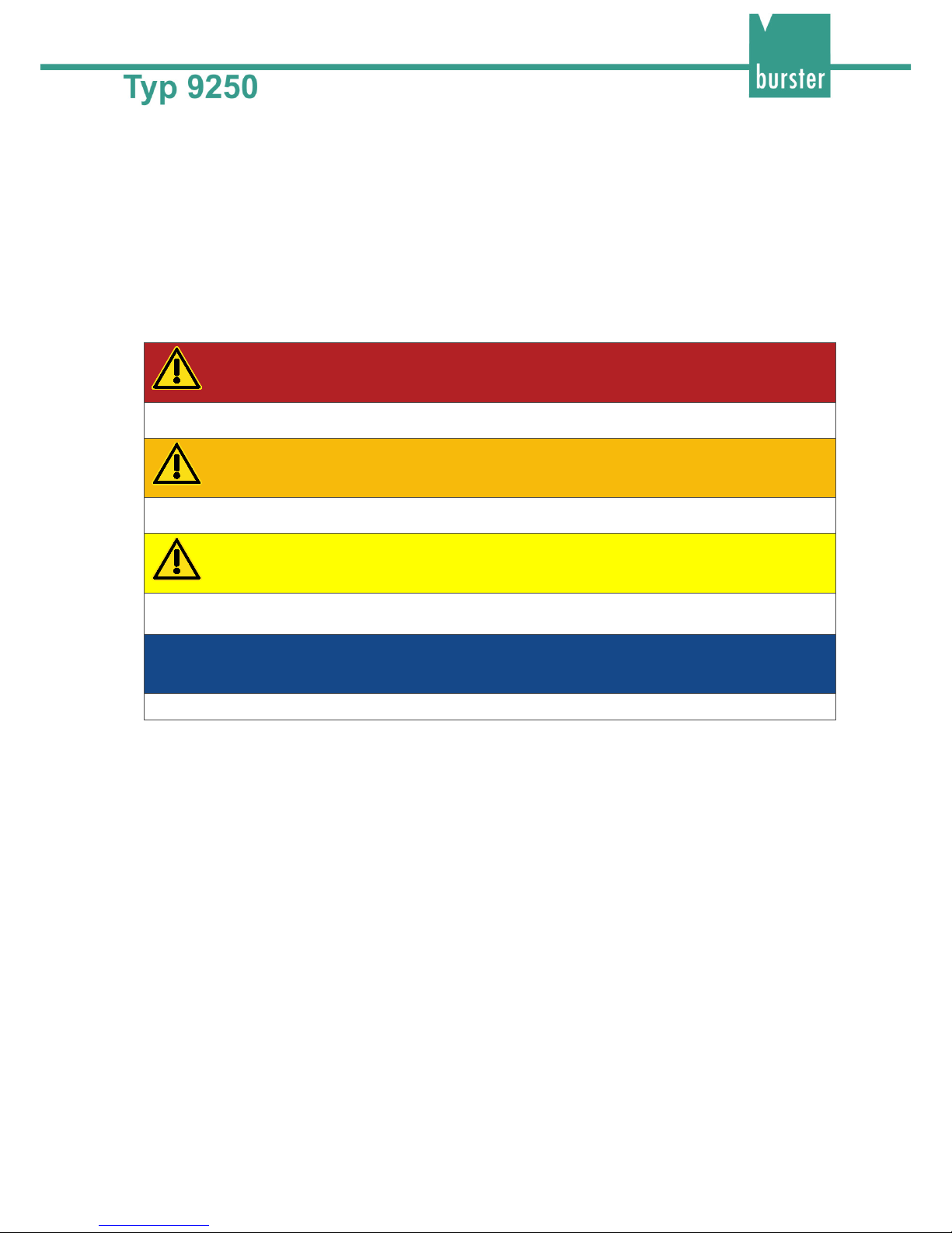
The following signal words are used in the operation manual according to the specified hazard
classification.
DANGER
High degree of risk: indicates a hazardous situation which, if not avoided, will result in death or serious
injury.
WARNING
Moderate degree of risk: indicates a hazardous situation which, if not avoided, may result in death or
serious injury.
CAUTION
Low degree of risk: indicates a hazardous situation which, if not avoided, could result in minor or
moderate injury.
NOTICE
Property damage to the equipment or the surroundings will result if the hazard is not avoided.
Note: It is important to heed these safety notices in order to ensure you handle the 9250
instrumentation amplifier correctly.
Follow the information given in the operation manual. IMPORTANT:
Page 8
8 of 67
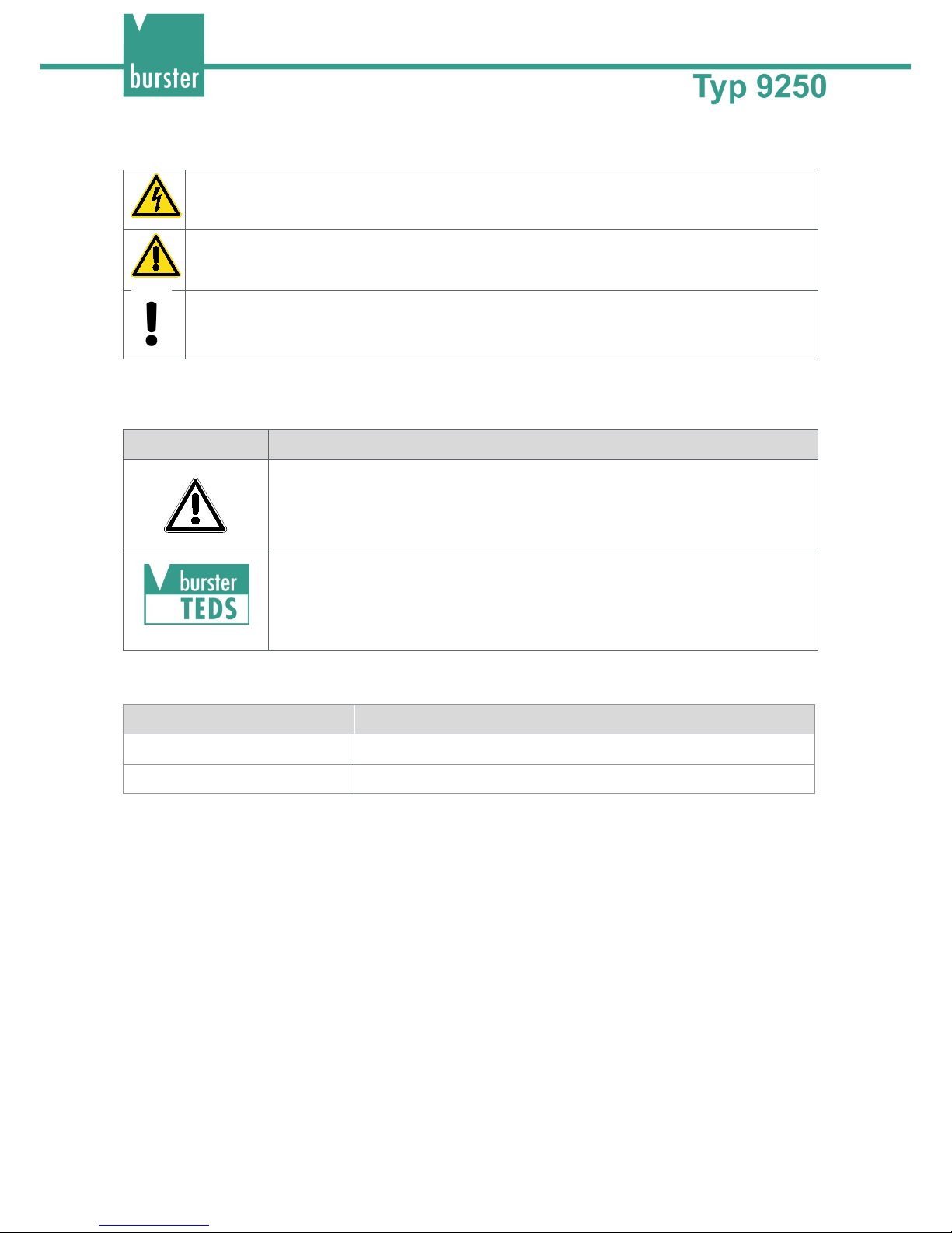
1.1.2 Pictograms
Electric shock hazard.
It is vital to follow the instructions.
Observe the advice for protecting the 9250 instrumentation amplifier.
1.2 Symbols
Symbol Description
See manual!
It is essential that you follow the information and instructions in the operation
manual for the 9250 instrumentation amplifier.
Follow safety instructions - Professional servicing only.
burster TEDS automatic sensor identification
For further details, please refer to section 3.7.1 "burster TEDS automatic sensor
identification" on page 16.
1.2.1 Conventions used in the instruction manual
Designation Description
[Text] Control buttons
"Term" Terms used in the instrument menus
Page 9
9 of 67
2 Introduction
Read the operation manual carefully before using the equipment, and keep for future IMPORTANT:
reference.
2.1 Intended use
DANGER
• The 9250 instrumentation amplifier must not be used in hazardous areas.
• The 9250 instrumentation amplifier is not intended as a substitute for safety
devices and protective equipment. Use safety devices and protective equipment.
• The 9250 instrumentation amplifier is not suitable for medical applications or where
people are at risk.
• Do not connect voltages that are higher than those permitted in the specification.
• Not suitable for safety-critical applications.
The 9250 instrumentation amplifier covers numerous areas of use. Designed for use with a variety of
analog sensors, the 9250 instrumentation amplifier can capture a huge range of output signals for
conditioning in fixed systems.
The intended use is defined to be:
• For industrial purposes
• For use in EMC-certified control cabinets
• For use solely with grounded DIN mounting rail
Industry-compatible connection and installation technologies make it easier for the user to adapt and
integrate the unit in existing mechanical and electrical environments. The outstanding measurement
quality also means it is ideal for use in both development and testing.
Typical applications of the 9250 instrumentation amplifier include:
• Production automation
• Integration of measurement data in a control environment
• Deployment in test and calibration laboratories
• Measuring and control equipment
Page 10

10 of 67
2.2 Customer service
2.2.1 Customer service department
For repair inquiries, please telephone our Service department on +49-7224-645-53, or email:
(Germany only). If you are outside Germany, you should contact your burster agent
(see also www.burster.com).
Please have the serial number to hand. The serial number is essential to establishing the definite
technical status of the instrument and providing help quickly. You will find the serial number on the type
plate of the instrumentation amplifier 9250.
2.2.2 Contact person
If you have any questions relating to the instrumentation amplifier 9250, please go directly to burster
präzisionsmesstechnik gmbh & co. kg, or if outside Germany, please contact your burster agent (see also
www.burster.com
Head office
burster präzisionsmesstechnik gmbh & co kg
Talstr. 1 - 5
DE-76593 Gernsbach
Germany
2.3 Download the test certificate
You have the option to download the test certificate for the instrumentation amplifier 9250 online. To do
this, you need to register at http://www.burster.com/en/registration/
. You can then download the test
certificate directly by entering the serial number.
2.4 Ambient conditions
2.4.1 Storage conditions
The following requirements must be met when storing the 9250 instrumentation amplifier:
• Store at temperatures between -25°C and +70°C
• Package the 9250 instrumentation amplifier sensor in clean materials
• Store in a dry environment
• No condensation
Page 11
11 of 67
2.4.2 Operating conditions
The following requirements must be met when operating the 9250 instrumentation amplifier:
• Always operate indoors
• Maximum height above sea level 2000 m
• Operate at temperatures between 0 °C and 60 °C
• Humidity: 80% up to +31 °C, decreasing linearly above that temperature to 50% at T
max
, no
condensation
• Class of protection: 3
• Transient overvoltage category: CAT II
• Supply voltage 11 ... 30 VDC
• The mounting rail must be connected to the protective earth
Note: Avoid condensation forming after transportation or storage.
2.4.3 Restrictions on use
DANGER
The 9250 instrumentation amplifier is not intended as a substitute for safety devices
and protective equipment.
Use safety devices and protective equipment.
The 9250 instrumentation amplifier does not pose a hazard if used within its specification and in
accordance with the safety regulations.
The manufacturer does not accept liability for any personal injury or property damage arising from
misinterpretation of measurement results.
2.4.4 Cleaning
DANGER
Electrical shock hazard.
Disconnect the 9250 instrumentation amplifier from the power supply before cleaning.
Disconnect the 9250 instrumentation amplifier from the power supply and use a slightly damp cloth to
clean the unit.
NOTICE
Do not immerse the 9250 instrumentation amplifier in water or hold it under running
water. Do not use strong cleaning agents as these may damage the 9250
instrumentation amplifier. Use a slightly damp cloth to clean the 9250 instrumentation
amplifier.
Page 12
12 of 67
2.5 Personnel
Personnel must be familiar with the relevant regulations. They must follow these regulations. Only trained
personnel who are familiar with the applicable safety regulations are permitted to operate the
instrumentation amplifier 9250.
We are happy to train your staff. To find out more, please look at our range of services at
www.burster.com
.
2.6 Contents of pack
The following components are supplied:
• 9250 instrumentation amplifier
• Operation manual
• Warranty document
• Test certificate
• DigiVision configuration and analysis software, free-of-charge version
2.7 Unpacking
DANGER
Electrical shock hazard.
Never switch on the 9250 instrumentation amplifier if it shows signs of damage
incurred in transit. Only ever use the 9250 instrumentation amplifier under the
conditions specified in this operation manual.
Inspect the 9250 instrumentation amplifier for damage. If you suspect that the unit has been damaged
during shipping, notify the delivery company within 72 hours.
The packaging must be retained for examination by a representative of the manufacturer and/or the
delivery company.
The 9250 instrumentation amplifier must be shipped only in its original packaging or in packaging capable
of providing an equivalent degree of protection.
2.8 Warranty
burster praezisionsmesstechnik gmbh & co kg provides a manufacturer's warranty for a period of 24
months after delivery.
Any repairs required during this time will be made without charge. This does not include damage arising
from improper use.
Please note the following when sending the 9250 instrumentation amplifier in for repair:
• If there is a problem with the 9250 instrumentation amplifier, please attach a note to the
instrument case summarizing the fault.
• Technical specifications subject to change at any time without notice.
We also state explicitly that we do not accept liability for consequential damage.
• The instrument must always be dispatched in suitable packaging.
Page 13
13 of 67
2.9 Conversions and modifications
Note: The warranty shall be deemed void immediately if you open or dismantle instrumentation
amplifier 9250 during the warranty period.
The 9250 instrumentation amplifier does not contain any parts that are intended to be serviced by the
user. Only the manufacturer's own qualified personnel are permitted to open the 9250 instrumentation
amplifier.
It is not permitted to make any changes to the 9250 instrumentation amplifier without the written
agreement of burster praezisionsmesstechnik gmbh & co kg. burster praezisionsmesstechnik gmbh & co
kg does not accept liability for damages or injury if this condition is disregarded.
Page 14
14 of 67
3 Device design
Please refer to the data sheet for the 9250 instrumentation amplifier for full details of dimensions, weight,
degree of protection etc.
3.1 Range of functions
The 9250 instrumentation amplifier is intended for the acquisition and processing of sensor signals.
The 9250 instrumentation amplifier is a fully configurable single-channel module that can be configured
both using buttons and via the USB port. The 9250 instrumentation amplifier is ideally suited to measuring
mechanical variables such as force, torque, pressure, acceleration, displacement and angle. Acquisition
and processing of strain-gage, potentiometric, TTL and standard signals is straightforward.
Signal conditioning parameters such as gain, offset, etc., which depend on the sensors used, can be
custom set using the DigiVision configuration and analysis software. A high-performance A/D converter
ensures accurate and high-speed acquisition of the analog sensor signals.
The DigiVision configuration and analysis software can be used to configure functions such as digital
filtering, selectable integration time, tare and MIN/MAX buffers.
The 9250 instrumentation amplifier itself generates a stable and precise sensor supply voltage. The 9250
instrumentation amplifier holds the calibration and configuration data securely against loss in the event of
power failure.
The 9250 instrumentation amplifier has two PLC inputs and two PLC outputs, so that the device can also
work independently to perform control tasks locally and directly.
3.2 Signal processing
The instrument provides the requisite signal amplification for the nature and type of connected sensor,
and uses a 24-bit analog-to-digital converter to digitize the signals. TTL signals are detected by means of
a quadrature decoder.
The built-in high-performance processor controls the digital-to-analog converter, which generates the
analog output signals.
3.3 Measurement quality
The measurement quality that can be achieved depends on numerous factors. Assuming that the
measurement setup is correct, it holds that:
• The best possible measurement results as regards precision and noise suppression are achieved
with longer integration times or, for digital filtering, with low cut-off frequencies.
• Therefore choose the longest integration time or the lowest cut-off frequency that is suitable for
your measurement task.
Page 15
15 of 67
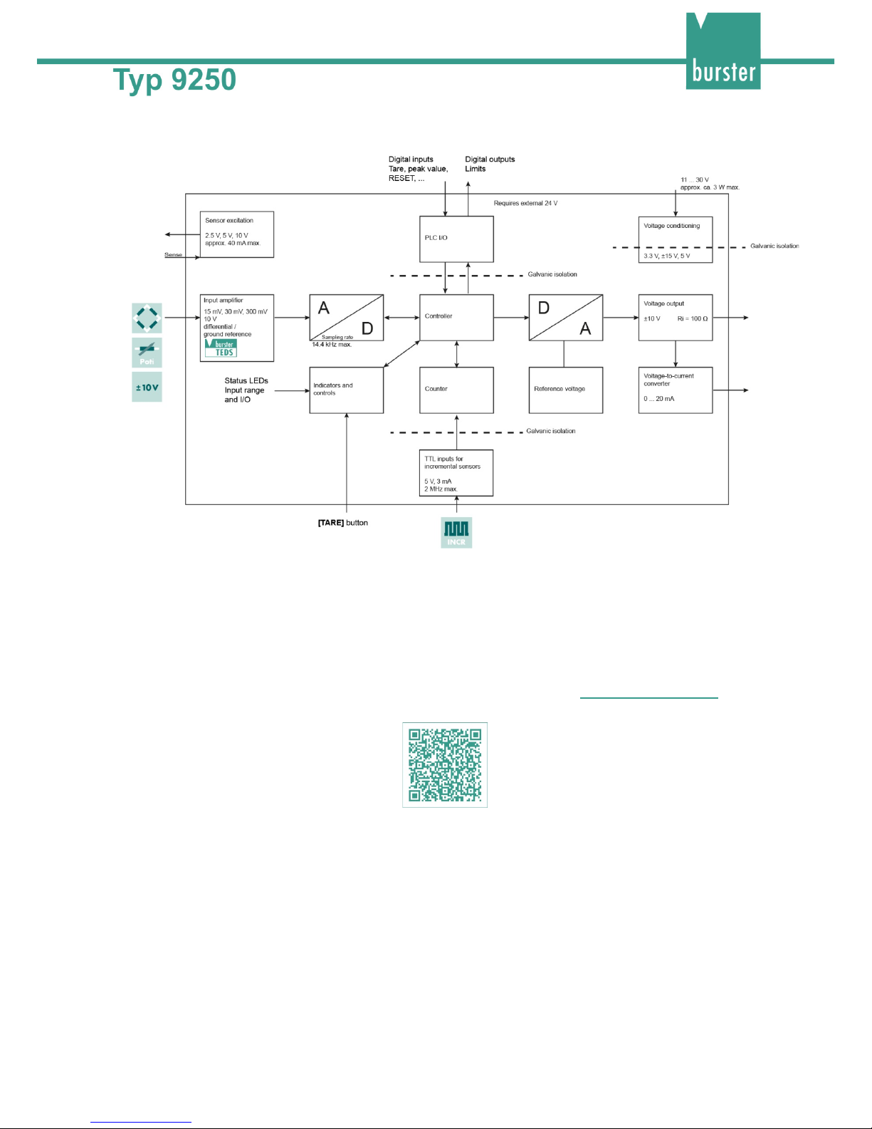
3.4 Block diagram and potentials
Diagram: 1 Block diagram of the 9250 instrumentation amplifier
The PLC inputs and outputs, the TTL inputs and the voltage supply are galvanically isolated from the
actual instrumentation electronics and therefore have their own ground terminals. A maximum voltage of
20 V is allowed between the respective terminals and PE.
3.5 Model versions
Please refer to the data sheet for details of the different model versions. You can obtain the latest data
sheet and additional information on the 9250 instrumentation amplifier from https://goo.gl/MQ27sG
or
simply use the QR code below:
Diagram: 2 QR code for the 9250 instrumentation amplifier
3.6 Power supply
The 9250 instrumentation amplifier can be operated with a voltage of 11 ... 30 VDC. The maximum power
consumption of the 9250 instrumentation amplifier is 3 W.
Page 16
16 of 67
3.7 Sensors suitable for use with the instrument
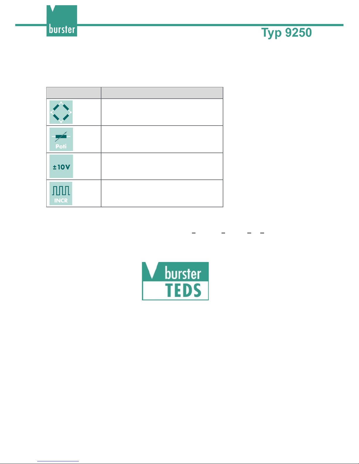
The 9250 instrumentation amplifier can process signals from a huge range of sensor technologies.
The 9250 instrumentation amplifier works with these sensor technologies:
Symbol Type
Strain-gage sensors
Potentiometers
Sensors with standard signal (process signal)
Incremental sensors
3.7.1 burster TEDS automatic sensor identification
The 9250 instrumentation amplifier uses the burster TEDS (Transducer Electronic Data Sheet) to provide
automatic sensor recognition, i.e. the instrument reads the relevant sensor specification from an
EEPROM, fitted in the sensor plug, and can then use this data to perform the necessary channel
configuration automatically. The memory chip in the sensor plug is programmed when the sensor is first
ordered or subsequently calibrated.
Diagram: 3 Label identifying burster TEDS
Page 17
17 of 67
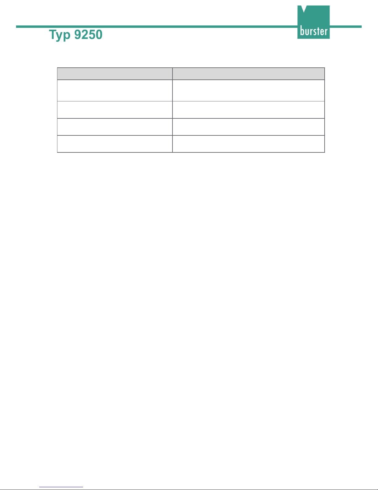
3.8 Fault indicators
Indication Fault description
Status LED flashing red rapidly
Fault after power-up
Sensor excitation not available
Internal malfunction
Status LED solidly red
Input overdrive
Output overdrive
Status LED flashing slowly alternately
red and green
Stay-set mode active: analog output does not
necessarily correspond to the input
Status LED flashing red rapidly and
green slowly
The ADC is not providing measurements because it has
been stopped by PLC input
Page 18
18 of 67
4 Controls and connections
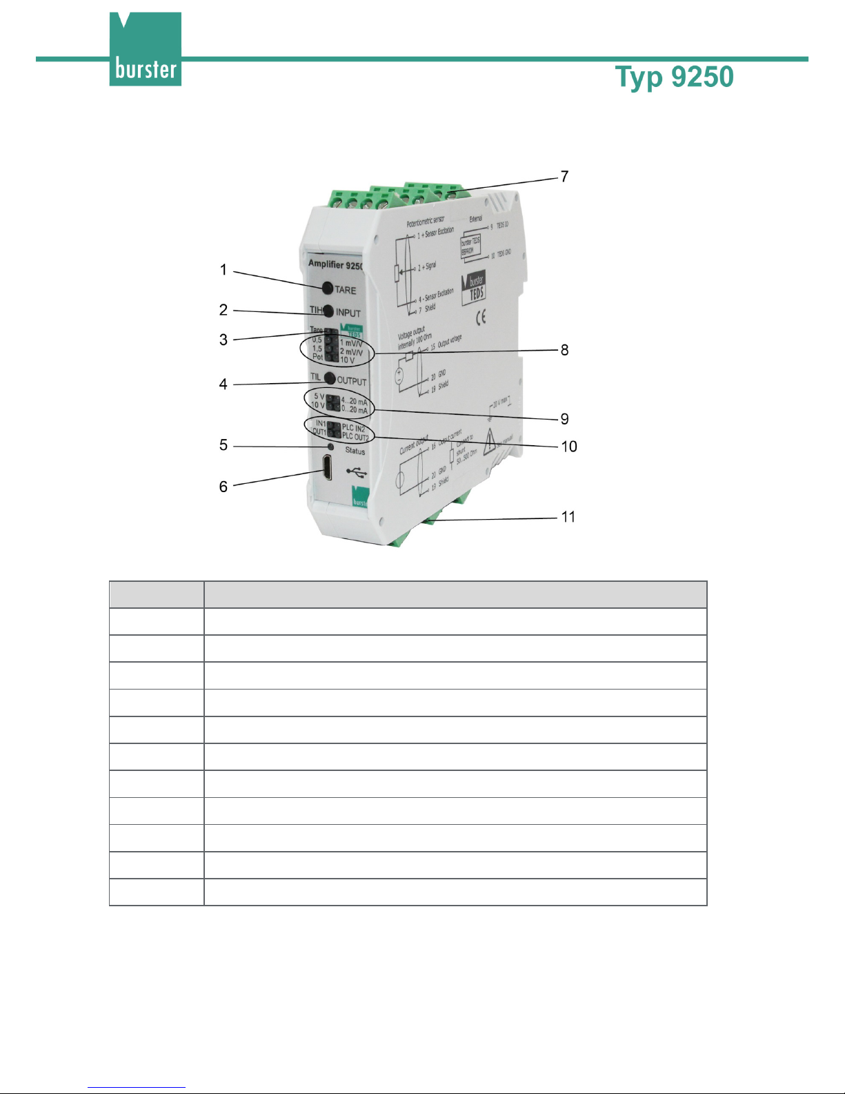
Diagram: 4 Front view
Label Description
1 [TARE] button
2 [TIH / INPUT] button
3 Tare indicator
4 [TIL / OUTPUT] button
5 Status indicator
6 Micro USB socket for configuration
7 Connecting terminals for sensors, output signal and operating voltage
8 Input configuration indicator (input LEDs)
9 Output configuration indicator (output LEDs)
10 Digital I/O indicator
11 Connecting terminals for sensors and supply voltage
Page 19
19 of 67
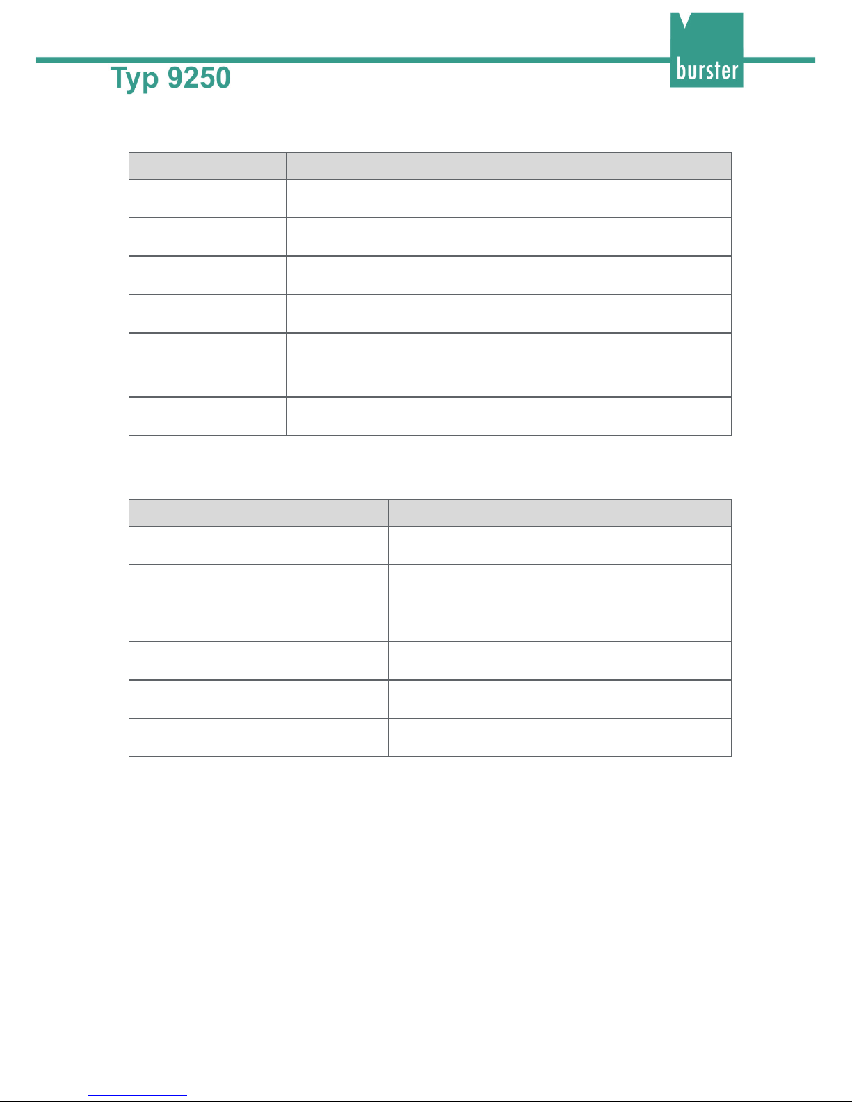
4.1 LEDs
LEDs Description
Flashing Lamp test on power-up
"Status" LED Status LED, dual green and red LED
"PLC" LEDs
Two LEDs for PLC-IN show the detected status of the two PLC inputs.
Two LEDs for PLC-OUT show the control state of the two PLC outputs.
"Output" LEDs
Four LEDs indicate the currently set analog output mode
(0 ... ±5 V, 0 ... ±10 V, 0 ... 20 mA, 4 ... 20 mA)
"Input" LEDs
Seven LEDs show the configuration presets made using the control
buttons. These LEDs remain off if the 9250 instrumentation amplifier was
configured via the interface and the settings do not match any of the
configuration presets.
"Tare" LED
Indicates whether the 9250 instrumentation amplifier is currently working
with a tare (illuminated) or without a tare (off).
4.2 Status LED (normal operation)
Indication Description
Status LED solidly red Boot phase lasting about 3 seconds
Status LED flashing green slowly Normal measurement mode
Status LED flashing red rapidly Input amplifier or output DAC in overdrive
Status LED flashing red slowly
Sensor excitation voltage too low (current limiting, test
during power-up)
Status LED flashing slowly alternately
red and green
Stay-set mode active: analog output does not
necessarily correspond to the input
Status LED flashing red rapidly and
green slowly
The ADC is not providing measurements because it has
been stopped by PLC input
Page 20
20 of 67
4.3 Control buttons
4.3.1 TARE button
The tare function can be used to correct for static offsets on the sensor channels. For instance you can
correct for a static background load caused by a tool changeover system by running the tare function
before every measurement. The [TARE] button initiates the taring process. For further information on
how to use this button, please see section 6.6 "Tare function" on page 41.
4.3.2 TIH / INPUT button
You can use the [TIH / INPUT] button to configure the input to the 9250 instrumentation amplifier.
Possible options are: 0.5 mV/V, 1.0 mV/V, 1.5 mV/V, 2.0 mV/V, potentiometer, 10 V, burster TEDS.
For further information on how to use this button, please see section 6.1 "Quick configuration – manual
configuration using buttons" on page 31.
4.3.3 TIL / OUTPUT button
You can use the [TIL / OUTPUT] button to select the analog output.
Possible options are: analog output 0 ... 5 V, analog output 0 ... 10 V, analog output 0 ... 20 mA, analog
output 4 ... 20 mA.
For further information on how to use this button, please see section 6.1 "Quick configuration – manual
configuration using buttons" on page 31.
4.4 Grounding and shielding
The 9250 instrumentation amplifier sensor must be grounded via the mounting rail.
Use suitable connecting cables for connecting sensors and communication interfaces and for the PLC I/O
signal control lines. Ideally you should connect sensors using burster connecting cables and with a
minimum possible length of cable.
We strongly recommend the following:
• As a general rule, keep sensor connecting leads as short as possible.
• When using control lines from remote PLC systems, make sure all the system components are
suitably grounded.
• When using detachable extension leads, make sure the shielding is continuous.
• Keep signal lines spaced apart from supply lines.
Page 21
21 of 67
4.5 Compatible sensors / inputs
4.5.1 Full-bridge strain-gage sensors
There are three measuring ranges to choose from:
• 0 ... ±15 mV
• 0 ... ±30 mV
• 0 ... ±300 mV
The inputs are differential inputs with no ground reference.
The following settings for the sensor excitation voltage are possible:
• OFF
• 2.5 V
• 5 V
• 10 V
The maximum output current is approximately 40 mA. The sensor excitation voltage is protected against
short-circuit.
4.5.2 Potentiometric sensors
• The excitation voltage has a fixed value of 5 V
• The measuring range is 0 ... ±5 V
The maximum output current is approximately 40 mA. The sensor excitation voltage is protected
against short-circuit. The negative input is connected internally to ground; an external connection is
not needed.
4.5.3 Voltage measurement / transmitter with voltage output
• The measuring range is 0 ... ±10 V
• The sensor excitation voltage is disabled
• The negative input is connected internally to ground; an external connection is not needed
• Transmitters with a voltage output up to ±10 V can be connected like a voltage source
• The transmitters must have a separate power supply
Page 22
22 of 67
4.5.4 TTL incremental sensors
• Any TTL signal source that is able to sink at least 3 mA can be connected.
• The signals are galvanically isolated from the rest of the electronics by optocouplers.
The incremental counter consists of a 32-bit counter and can therefore count from -2,147,483,648 to
+2,147,483,647. If the incremental counter reaches the end of the range, an overflow occurs and the
counter continues counting from the opposite end of the range. You should therefore avoid an overflow.
The 9250 instrumentation amplifier works with 4-edge sampling, i.e. one signal period on the A-line or Bline produces 4 counter increments.
The following incremental modes are available:
• Totalizing counter
The pulses are counted until overflow. The analog output signal represents the count. The "Tare"
function ([TARE] button) can be used to reset the counter.
• Angle measurement mode
By specifying the number of pulses per revolution, the angle from incremental rotary encoders
can be converted into an analog value or scale value. The output value is automatically reset
from e.g. 360° back to 0° when an overflow occurs. The "Tare" function ([TARE] button) can be
used to reset the counter.
• Speed measurement mode
The pulses are counted in three selectable time windows (10 ms, 100 ms, 1 s).
The count reached in the time window is therefore proportional to the speed, and the analog
output signal reflects the count. The "Tare" function ([TARE] button) can be used to reset the
counter.
4.6 Outputs
4.6.1 Analog outputs
The 9250 instrumentation amplifier has a configurable voltage output and a current output. The following
base configurations are possible:
• 0 ... ±5 V
• 0 ... ±10 V
• 0 ... 20 mA
• 4 ... 20 mA
Note: Only one of the outputs at a time is active and calibrated.
For instance, if the voltage output is enabled, the current output continues to operate alongside without
being calibrated, and vice versa. The outputs can be configured largely to suit, and are not galvanically
isolated from the instrumentation electronics.
Page 23
23 of 67
4.7 PLC inputs
The 9250 instrumentation amplifier has two mutually separate PLC inputs that can be assigned different
functions. Possible options here are:
• Tare/Reset the counter
• Reset the tare
• Reset the MIN/MAX value
• Reset the limit buffer 1 or 2
• HOLD function
Note: The PLC inputs are galvanically isolated from the instrumentation electronics but not from the
PLC outputs.
4.8 PLC outputs
The 9250 instrumentation amplifier has two mutually separate PLC outputs that can be assigned different
functions.
Possible options here are:
• Operation of the upper/lower dynamic limit threshold:
The output is set while the measurement is above/below the threshold. Once this condition is no
longer met, the output is cleared again (dynamic behavior).
• Operation of the upper/lower static limit threshold:
The output is set while the measurement is above/below the threshold, and remains set even
when this condition is no longer met. It can only be cleared again by a suitable RESET signal at
the PLC input.
• Operation of window mode:
The output is set while the measurement signal lies between a lower and upper limit threshold.
Once the signal has left this range, the output is cleared. If the signal subsequently satisfies this
condition again, the output is set again (dynamic behavior).
Note: The PLC outputs are galvanically isolated from the instrumentation electronics but not from the
PLC inputs.
Page 24
24 of 67
4.9 Reading burster TEDS data
The 9250 instrumentation amplifier supports burster TEDS for strain-gage, potentiometric and high-level
sensors. Change the input to the 9250 instrumentation amplifier over to burster TEDS (please see section
6.1 "Quick configuration – manual configuration using buttons" on page 31). The 9250 instrumentation
amplifier then reads the TEDS chip for the connected sensor and configures its own parameters
accordingly.
Note: If there is no (valid) sensor with TEDS chip connected, you are not able to select burster TEDS
for the input. If it is found when reading the data that it is not possible to set a sensible set of
device parameters from the available information, the process is terminated and the previous
settings are retained.
4.10 MIN and MAX value
The 9250 instrumentation amplifier has a buffer for the MIN value and MAX value. The value recorded for
the live maximum measured value (MAX value) remains at the highest value reached so far, even if the
measurement signal has since fallen. The MAX value is overwritten as soon as a new measurement
signal exceeds the latest MAX value. You can reset the MAX value using a RESET signal at the PLC
input. The same behavior applies to the MIN value when the measurement signal falls below this value.
Page 25
25 of 67
4.11 Connections
Terminal assignments for the screw terminals on the 9250 instrumentation amplifier:
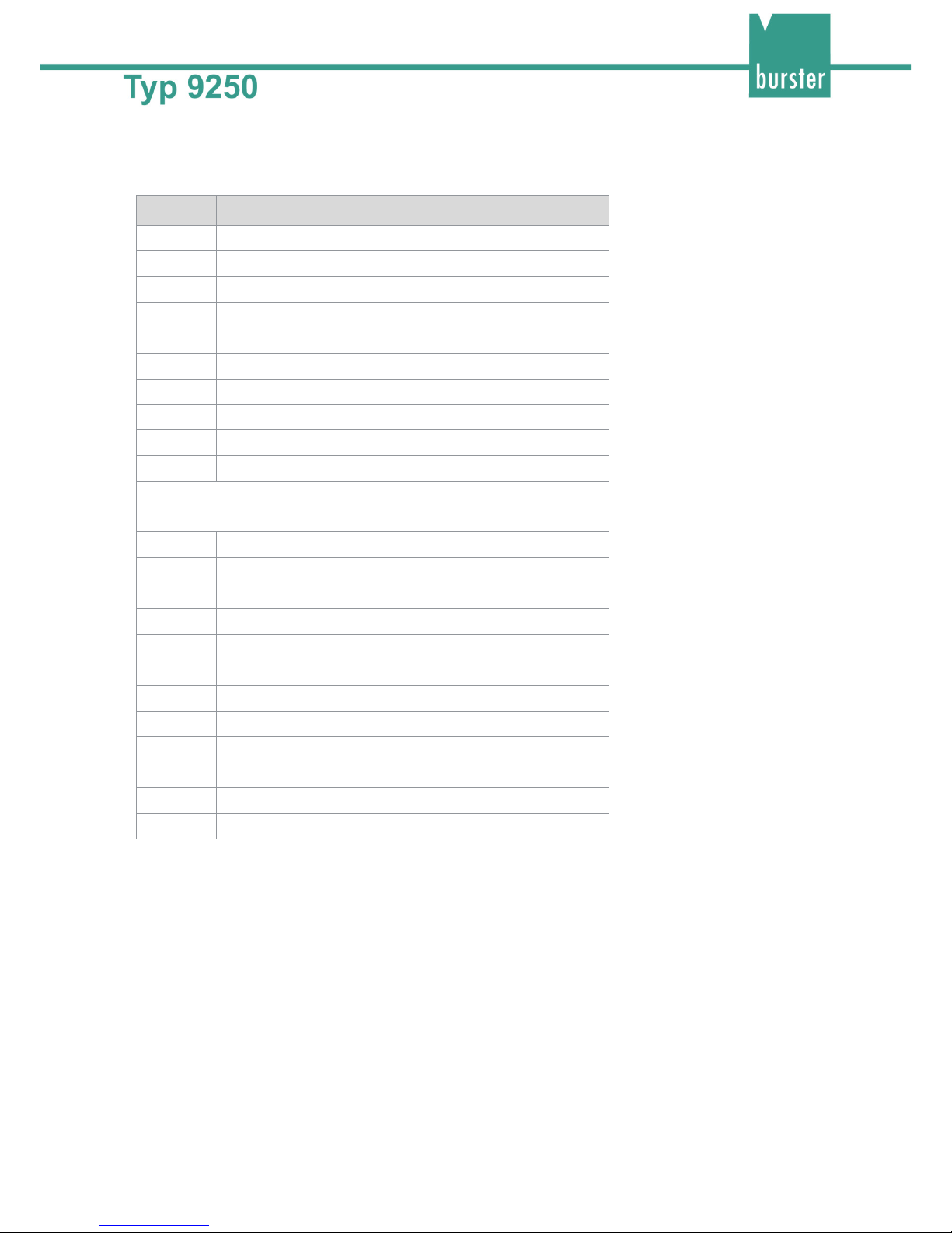
Number Designation
1 + sensor excitation
2 + signal
3 - signal
4 - sensor excitation
5 + sense
6 - sense
7 shield
8 TTL GND
9 TEDS IO
10 TEDS GND
11 supply voltage 11 ... 30 VDC
12 supply voltage GND
13 TTL input A
14 TTL input B
15 voltage output 0 ... ±10 V
16 current output 0 ... 20 mA
17 PLC supply GND
18 +24 V PLC supply
19 shield
20 analog output GND
21 PLC input 1
22 PLC input 2
23 PLC output 1
24 PLC output 2
Page 26
26 of 67
4.11.1 Connecting strain-gage sensors
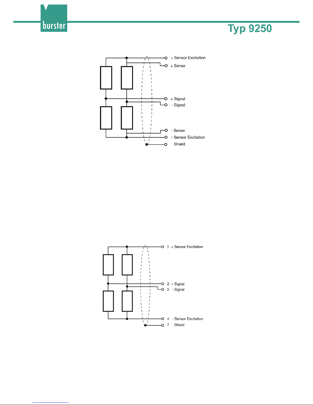
Diagram: 5 Strain-gage connection method
You can connect strain-gage sensors, with or without sense leads, to the 9250 instrumentation amplifier.
Sense lines are used for correcting losses in the cable in order to obtain optimum results regardless of
the cable length.
If the strain-gage sensors are equipped with sense-lead terminals, sense leads should be used, and if
using extension leads, these should also include sense lines.
If you are using strain-gage sensors that have no sense-lead terminals, you can still connect these
sensors directly to the 9250 instrumentation amplifier. If extension leads are needed, these should include
sense leads. In this case, make a connection between +sense and +excitation and between -sense
and -excitation at the extension cable end closest to the strain-gage sensor.
Connecting strain-gage sensors without sense leads
Connect strain-gage sensors without sense leads as follows:
Diagram: 6 Strain-gage sensors without sense leads
Page 27
27 of 67
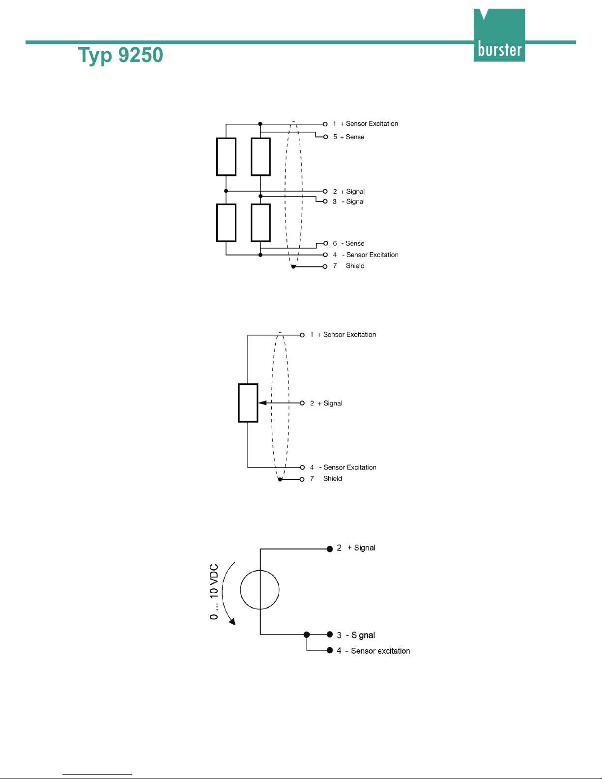
Connecting strain-gage sensors fitted with sense leads
Connect strain-gage sensors fitted with sense leads as follows:
Diagram: 7 Strain-gage sensors with sense leads
4.11.2 Connecting potentiometric sensors
Connect potentiometric sensors as follows:
Diagram: 8 Potentiometric sensors
4.11.3 Connecting transmitters that have a voltage output
Connect the transmitters as follows:
Diagram: 9 Transmitter with voltage output
The input range is 0 ... ±10 V.
Note: The 9250 instrumentation amplifier does not provide any excitation voltages for transmitters.
Page 28
28 of 67
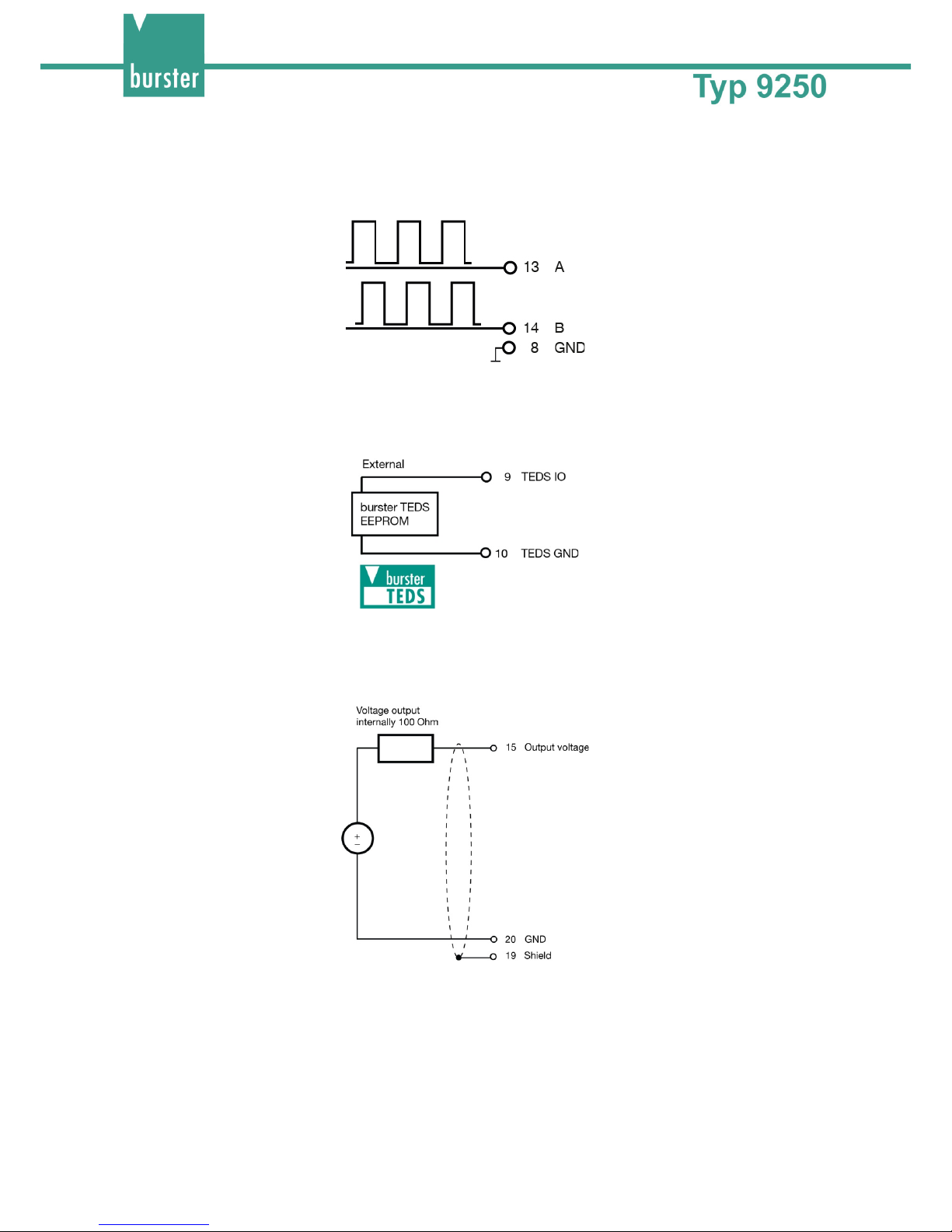
4.11.4 Connecting incremental sensors
Connect incremental sensors as follows:
Diagram: 10 Incremental sensors
4.11.5 burster TEDS connection
Applies to all sensors equipped with the burster TEDS option.
Diagram: 11 burster TEDS connection
4.11.6 Voltage output
Terminal assignment for the voltage output:
Diagram: 12 Terminal assignment for the voltage output
Page 29
29 of 67
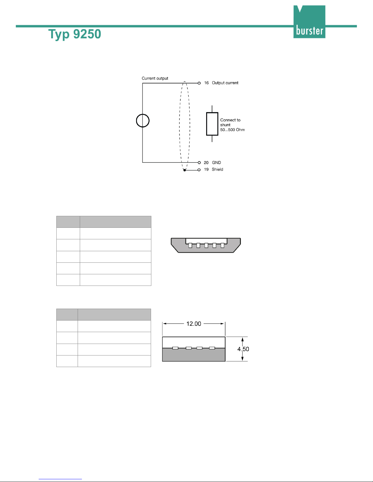
4.11.7 Current output
Terminal assignment for the current output:
Diagram: 13 Terminal assignment for the current output
4.11.8 USB port
The USB port complies with the USB 2.0 standard and has the standard pin assignment. The built-in
connector on the 9250 instrumentation amplifier is a "USB 2.0 Micro-B" plug.
Pin Name
Diagram: 14 USB Micro-B [mm]
1 + 5 V
2 data -
3 data +
4 ID (unassigned)
5 GND
The connector fitted on the supplied cable is a “type A USB” plug.
Pin Name
Diagram: 15 USB A [mm]
1 + 5 V
2 data -
3 data +
4 GND
Page 30
30 of 67
5 Using the instrument for the first time
DANGER
Electrical shock hazard.
• Never switch on the 9250 instrumentation amplifier if it shows signs of damage
incurred in transit. Only ever use the 9250 instrumentation amplifier under the
conditions specified in this operation manual.
• The 9250 instrumentation amplifier must not be used in hazardous areas.
• Do not connect voltages that are higher than those in the specification. The ranges
supported are listed in the data sheet for the 9250 instrumentation amplifier.
5.1 Installation / Removal
WARNING
Install the 9250 instrumentation amplifier only on a grounded mounting rail in a
grounded control cabinet.
The 9250 instrumentation amplifier is intended to be fitted on a grounded DIN EN 60715 mounting rail in
a grounded control cabinet.
Installation
1 Place the top edge of the fastening mechanism on the mounting rail.
2 From the front, press the 9250 instrumentation amplifier against the mounting rail until you
can hear the fixing clip engage.
3 Pull the 9250 instrumentation amplifier gently forward to check that it is held securely.
Removal
1 Use a screwdriver to release the fixing clip on the bottom edge of the 9250 instrumentation
amplifier from the mounting rail.
2 Tilt the 9250 instrumentation amplifier slightly upwards and lift it off the mounting rail by its
top edge.
Page 31
31 of 67
6 Configuring the unit
6.1 Quick configuration – manual configuration using
buttons
6.1.1 Important information
If you want to operate the 9250 instrumentation amplifier solely via the quick configuration IMPORTANT:
facility then it will use a default sampling rate of 1200 measurements/s with digital filter
disabled. Settings that you make via the USB port will be overwritten.
6.1.2 Selecting the input
A button is provided for choosing between full-bridge strain-gage sensors with rated outputs of 0.5 mV/V,
1.0 mV/V, 1.5 mV/V, 2.0 mV/V, potentiometric sensors, a ±10 V voltage input or sensors equipped with
burster TEDS.
1 Press the [TIH / INPUT ] button briefly to activate Input mode for making your selection.
The LED for the option currently selected starts to flash.
2 Press the [TIH / INPUT ] button briefly to activate the next available option. All available
options are offered in a cycle.
Note: You can only use the burster TEDS option if the 9250 instrumentation amplifier has
detected that a sensor equipped with burster TEDS is connected.
3 If you do not press the [TIH / INPUT] button for a second time within 3 seconds, the
selection LED stops flashing and no change is made to the settings.
4 To adopt the currently made selection, press and hold the [TIH / INPUT] button for about 3
seconds.
6.1.3 Selecting the analog output
You can choose from: analog output 0 ... ± 5 V, analog output 0 ... ± 10 V, analog output 0 ... 20 mA,
analog output 4 ... 20 mA.
1 Press the [TIL / OUTPUT ] button briefly to activate Input mode for making your selection.
The LED for the option currently selected starts to flash.
2 Press the [TIL / OUTPUT] button briefly to activate the next available option. All available
options are offered in a cycle.
3 If you do not press the [TIL / OUTPUT] button for a second time within 3 seconds, the
selection LED stops flashing and no change is made to the settings.
4 To adopt the currently made selection for the analog output, press and hold the [TIL /
OUTPUT] button for about 3 seconds.
Page 32
32 of 67
6.1.4 Performing sensor teach-in
1 Press the [TIH / INPUT] button and the [TIL / OUTPUT] button simultaneously for about 3
seconds. This activates calibration mode. The input LEDs show a light moving towards
"TIL" (Teach-In Low).
2 Press the [TIL / OUTPUT] button briefly to perform the teach-in for the lower point of the
two-point calibration first. 0 % of the analog output range (e.g. 0 V, 0 mA, 4 mA) will
subsequently be output for this value. Press any other button to cancel the process.
3 Once the teach-in has been performed, the 9250 instrumentation amplifier confirms the
selection by making all the input LEDs flash.
4 Press the [TIH / INPUT] button briefly to teach the upper point of the two-point calibration
next. 100 % of the analog output range (e.g. 5 V, 10 V, 20 mA) will subsequently be output
for this value. Press any other button to cancel the process.
5 The 9250 instrumentation amplifier uses the teach-in measurements to calculate the
rescaling calibration, which it then saves. A short run of lights moving in the opposite
direction indicates that the calculation has been completed successfully. The unit can then
be used with the new calibration.
Page 33
33 of 67
6.2 Additional settings via DigiVision
6.2.1 System requirements
Operating systems
Windows 7, Windows 8, Windows 10
Processor:
Pentium 1200 MHz minimum, Pentium 2.0 GHz recommended
Graphics card:
At least VGA 800 x 600, minimum 256 colors
Memory:
At least 1024 MB RAM
Hard disk:
Approx. 500 MB free space
Input devices:
MS-compatible mouse, standard keyboard
Font setting:
Small fonts
6.2.2 Software installation
To install the DigiVision configuration and analysis software, the user needs to be logged IMPORTANT:
on as an administrator.
1 To start installing the DigiVision configuration and analysis software, insert the supplied
CD-ROM in the CD-ROM drive.
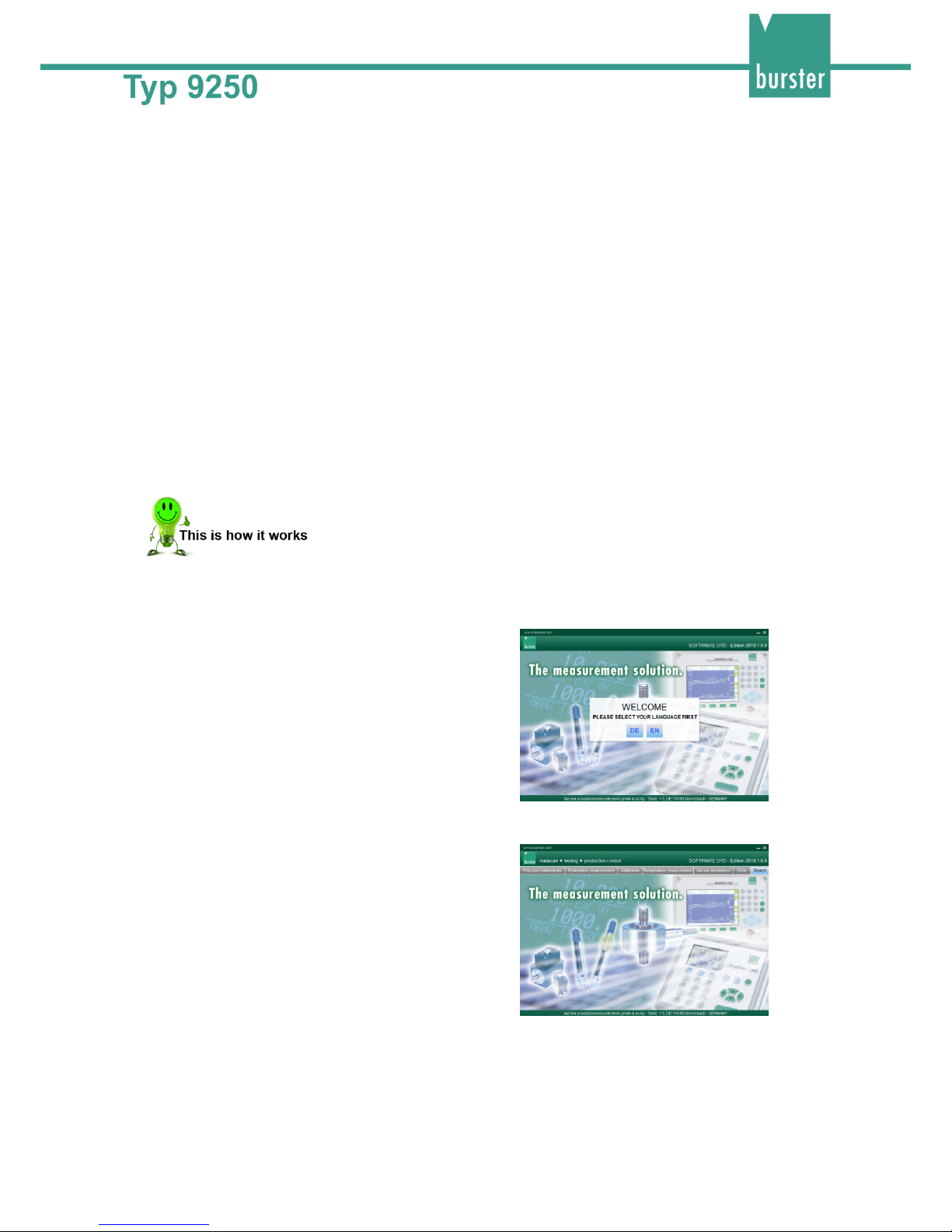
2 Choose your language.
3 Click “Sensor Electronics” and choose
“9250”.
Note: If Microsoft .NET Framework 4.0 is not
already installed on the PC, it is installed
automatically.
Page 34
34 of 67
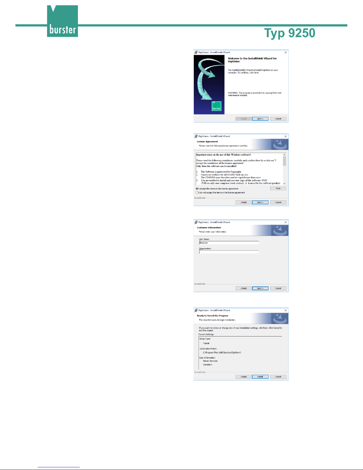
4 Click “Next”.
5 Accept the license agreement then click
"Next >". The installation will terminate if you
do not accept the license agreement.
Note: The next installation screen lets you
review all the relevant information about
the software version you are installing.
After installation, you can also view this
information in the "readme.txt" file.
6 Click "Next >". Enter a user name and the
name of your organization or company.
7 Choose a folder and click “Next >”. Check
your chosen information and click “Install”.
Page 35
35 of 67
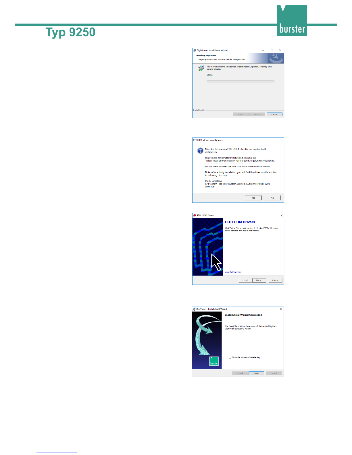
8 The installation may take several minutes.
9 Click “Yes” to install the instrument driver.
10 Click “Extract” to unpack the driver package
and launch the installer.
11 Follow the instructions of the Device Driver Installation Wizard.
12 The DigiVision configuration and analysis
software has been successfully installed on
your system. Click the "Finish" button to
close the Setup wizard.
Page 36
36 of 67
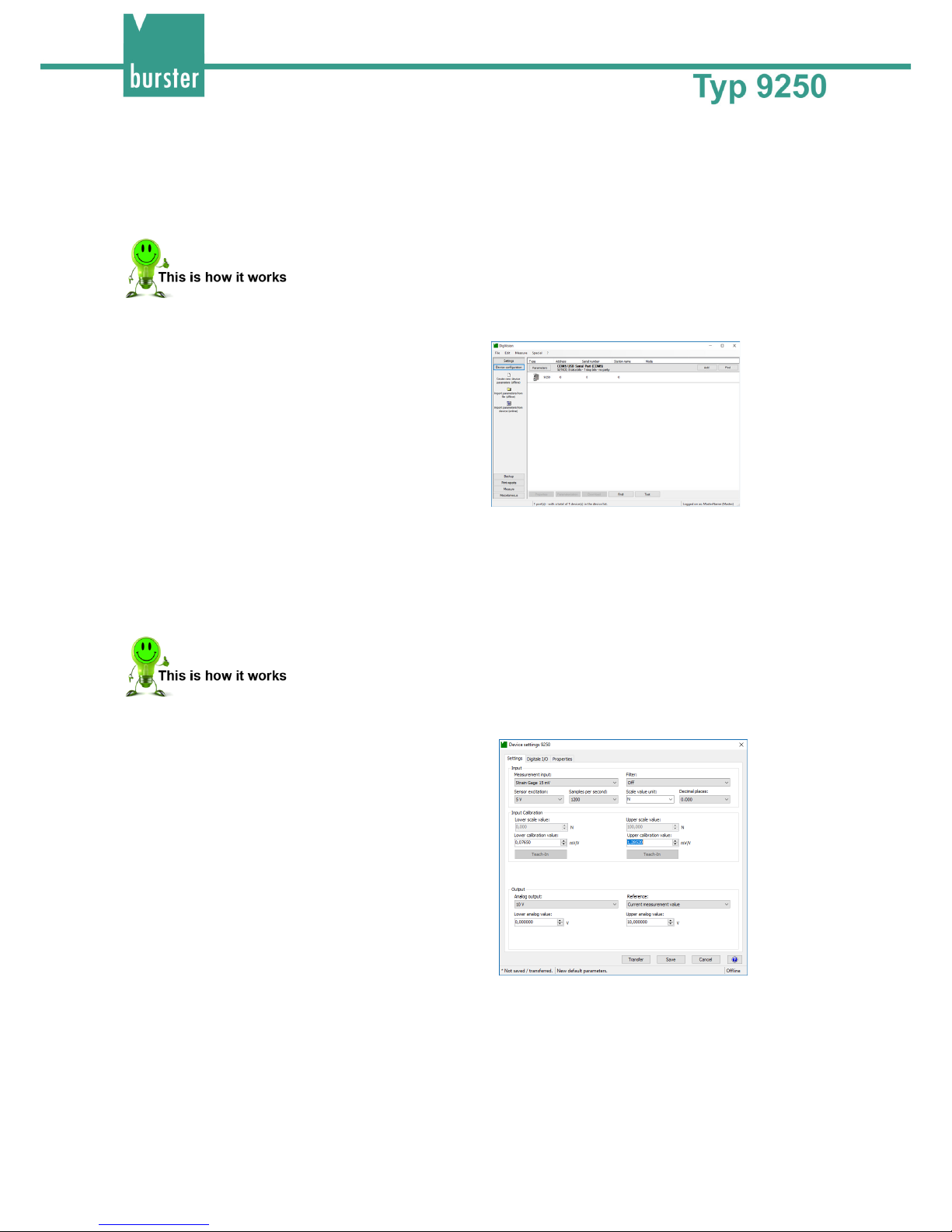
6.3 Device list
You can use the device finder facility to detect and display all the connected 9250 instrumentation
amplifiers automatically.
1 Run the DigiVision configuration and analysis software.
2 Click "Find". You are shown a list of all
available serial ports, and a search is carried
out for any connected 9250 instrumentation
amplifiers. All the connected 9250
instrumentation amplifiers that have been
found are listed under the ports.
6.4 Device settings
Once the devices have been identified, you can configure the 9250 instrumentation amplifiers via the
device list.
1 Select the port you want to configure by clicking on it.
2 Click "Parameters". This opens the Device
settings window.
Page 37
37 of 67
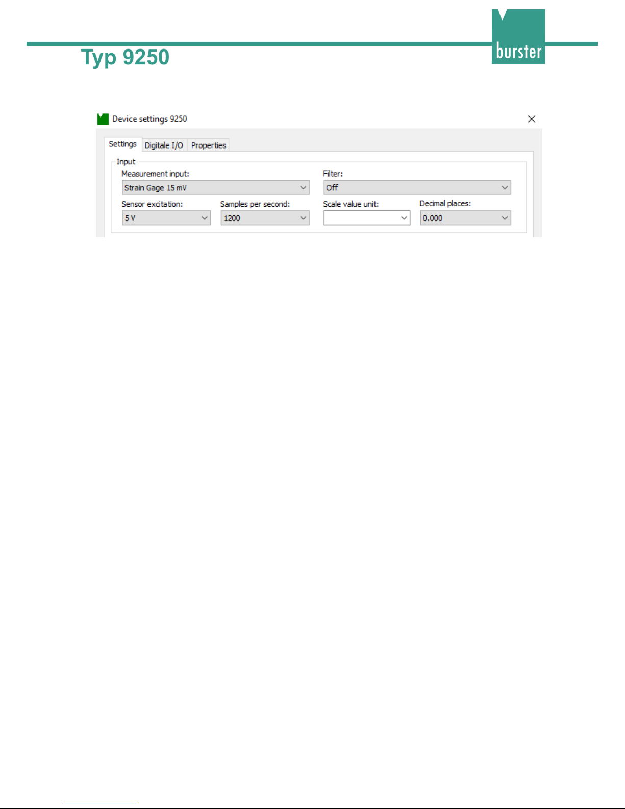
6.4.1 Device settings
Diagram: 16 Device settings 9250
Measurement mode
In order to be able to use 100% of the measurement range of the connected sensor, the selected input
range must be ≥ the sensor rated output.
The following input measurement ranges are possible:
• 0 ... ±15 mV
• 0 ... ±30 mV
• 0 ... ±300 mV
• Potentiometer
• 0 ... ±10 V
• TTL increments
Decimal places
The setting for decimal places refers to the measured value. The number of decimal places can range
from 0 to 6. The number of decimal places is permanently set to four for calibration values. If the
connected sensor supports less than four decimal places, trailing zeros can be added to fill the remaining
places.
The option to set the number of decimal places is only available for the bus model.
Unit
Set here the physical units required for the measurement. If the units that you require are not included in
the list, you can also enter these by hand.
For rescaling with sensors, please refer to section 7 "Rescaling in order to calibrate the 9250
instrumentation amplifier with sensors" on page 42.
The option to set the units is only available for the bus model.
Sensor excitation voltage
The following sensor excitation voltages can be chosen:
• OFF
• 2.5 V
• 5 V
• 10 V
The correct value for the sensor excitation voltage is listed in the relevant data sheet or in the test and
calibration certificate.
Page 38
38 of 67
Filter
A filter is available for filtering certain measurement signals. The filter cut-off frequency can be selected in
steps between 4 and 700 Hz. When set to "Off", the measurement signals are processed without filtering.
Samples per second
Enter here the measurement rate at which you want the measurement to run at the input amplifier and at
the output. The measurement rate applies to both sides. The maximum measurement rate available as
standard is 1200 measurements/s. Optionally, up to 14,400 measurements/s are possible.
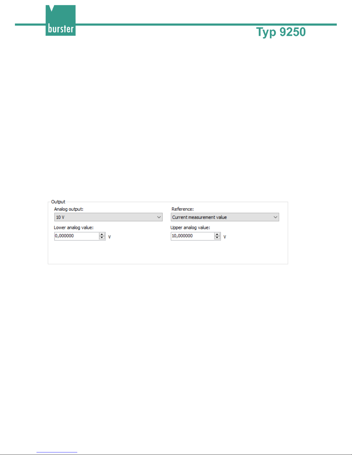
6.4.2 Configuring the analog output
The 9250 instrumentation amplifier has a configurable voltage output and a current output. The following
base configurations are possible:
• 0 ... ±5 V
• 0 ... ±10 V
• 0 ... 20 mA
• 4 ... 20 mA
Only one of the analog outputs at a time is active and calibrated. For instance, if the voltage output is
enabled, the current output continues to operate alongside without being calibrated, and vice versa.
Diagram: 17 Configuring the analog output
The lower analog value always relates to the lower calibration value, and the upper analog value to the
upper calibration value.
The reference for the output signal from the analog output can be chosen. The analog output is then
referred to the selected option.
• Current measurement value (default)
• MIN peak-value buffer
• MAX peak-value buffer
Example:
A tension and compression load cell is meant to span a current range of 4 to 20 mA in both load
directions. In this case, the zero point of the sensor must be set to 12 mA in order to be able to output
both load directions. The lower analog value is set to 4 mA and the upper analog value to 20 mA.
Page 39
39 of 67
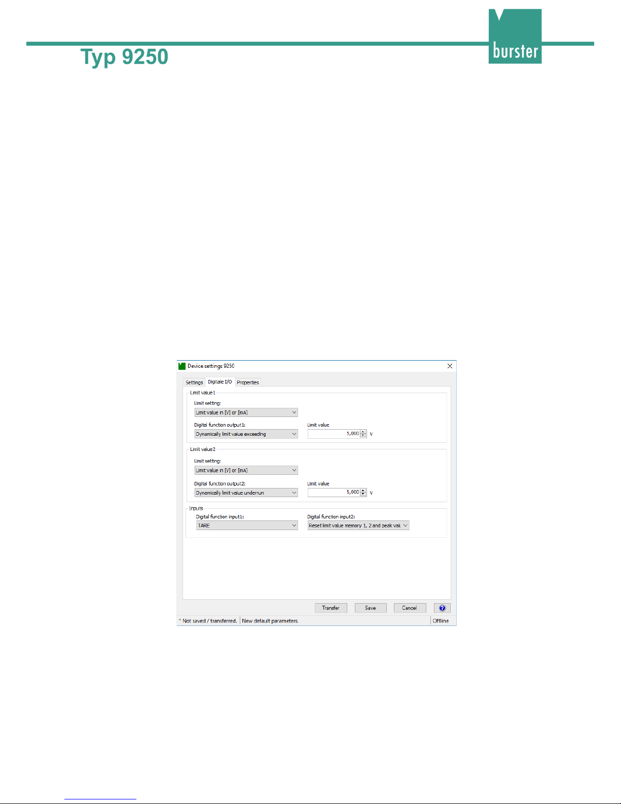
6.4.3 Configuring the PLC I/O - Digital inputs / Limits
You have the option on the 9250 instrumentation amplifier to configure two outputs and two inputs.
For the outputs, when setting the limits, you can specify whether the value is entered as a scale value or
analog output value. Two limits are entered if one of the window modes is selected.
6.4.4 Device settings - Limits
The following selection options are available:
• Dynamically limit value exceeding
• Dynamically limit value underrun
• Statically limit value exceeding (limit buffer)
• Statically limit value underrun (limit buffer)
Window mode
• Above lower limit AND below upper limit, dynamic
• Above upper limit OR below lower limit, dynamic
• Above upper limit OR below lower limit, static
Diagram: 18 Configuring the limits
Page 40
40 of 67
6.4.5 Configuring the digital inputs
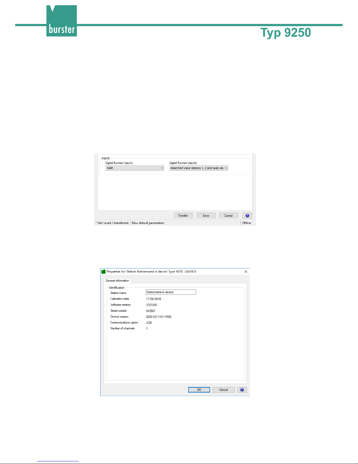
The following selection options are available:
• TARE
• TARE reset
• Peak-value memory MIN/MAX
• Reset limit value memory 1
• Reset limit value memory 2
• Reset limit value memory 1 and 2
• Reset limit value memory 1, 2 and peak-value memory MIN/MAX
• HOLD
Diagram: 19 Configuring the digital inputs
6.4.6 Device settings - Properties
You can make or view the following settings under Device settings 9250 > Properties (“Properties for ...”):
Diagram: 20 Device settings ("Properties for ...")
Page 41
41 of 67
• Station name
You can enter any device name of your choice in this field.
• Calibration date
The calibration date is updated with the date and time whenever new calibration data is
transferred to the 9250 instrumentation amplifier.
• Software version
Shows the current version of the software in the 9250 instrumentation amplifier.
• Serial number
Shows the serial number of the connected 9250 instrumentation amplifier.
• Device version
Shows the device version of the connected 9250 instrumentation amplifier.
1 Run the DigiVision configuration and analysis software.
2 Double click the 9250 instrumentation amplifier. The “Properties for ...“ window will be
opened.
6.5 Tare function
The tare function can be used to correct for static offsets on the sensor channels. For instance you can
correct for a static background load caused by a tool changeover system by running the tare function
before every measurement. The [TARE] button initiates a taring process.
1 Press the [TARE] button briefly. The Tare LED will start flashing.
2 Press and hold the [TARE] button for about 3 seconds while the Tare LED is flashing. The
Tare LED is your indication that "Taring" is active.
3 If you do not press the [TARE] button for a second time within 3 seconds, the Tare LED
stops flashing and no action has been initiated.
4 Releasing the [TARE] button activates or deactivates the tare function.
Page 42
42 of 67
7 Adjustment in order to calibrate the 9250
instrumentation amplifier with sensors
Calibration in the form of adjustment is needed in order to define the relationship between the electrical
signals measured by the connected sensors and the measured values that will be displayed.
7.1 Adjustment with strain-gage sensors
The 9250 instrumentation amplifier can be calibrated by a choice of rescaling techniques:
• Adjustment using a physical variable
• Adjustment using data entered from the test and calibration certificate for the strain-gage sensor
The following sections describe in greater detail the different calibration and rescaling options.
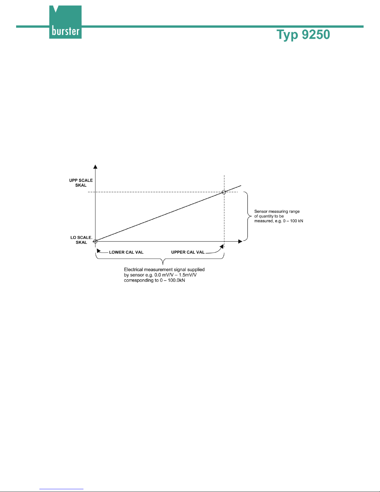
Diagram: 21 Characteristic sensor curve
The relationship between the electrical measurement signal from the connected strain-gage sensor (lower
calibration value, upper calibration value) and the measured value to be displayed (lower scale value,
upper scale value) is set out below. It is a simple two-point calibration.
The values are related as follows:
Lower scale value
Lower calibration value
Upper scale value
Upper calibration value
The lower calibration value is the electrical signal from the strain-gage sensor when the “load” given by
the lower scale value is applied (usually the zero point of the strain-gage sensor). Since the zero point of
a strain-gage sensor tends to shift from the origin as a result of the way the sensor is mounted
(components used to transfer the force exert a pre-load themselves) or material aging, the electrical value
specified under "zero point" in the test and calibration certificate rarely tallies with the value actually
measured. We therefore advise that you always perform a teach-in for this value.
Other terms:
Rated load
upper scale value or upper analog value
Zero signal
zero point, zero signal without assembly parts, lower calibration value
Rated output
output signal at rated load, rated output in preferential measurement direction, upper
calibration value
Page 43
43 of 67
7.1.1 Rescaling using a physical variable by the teach-in method
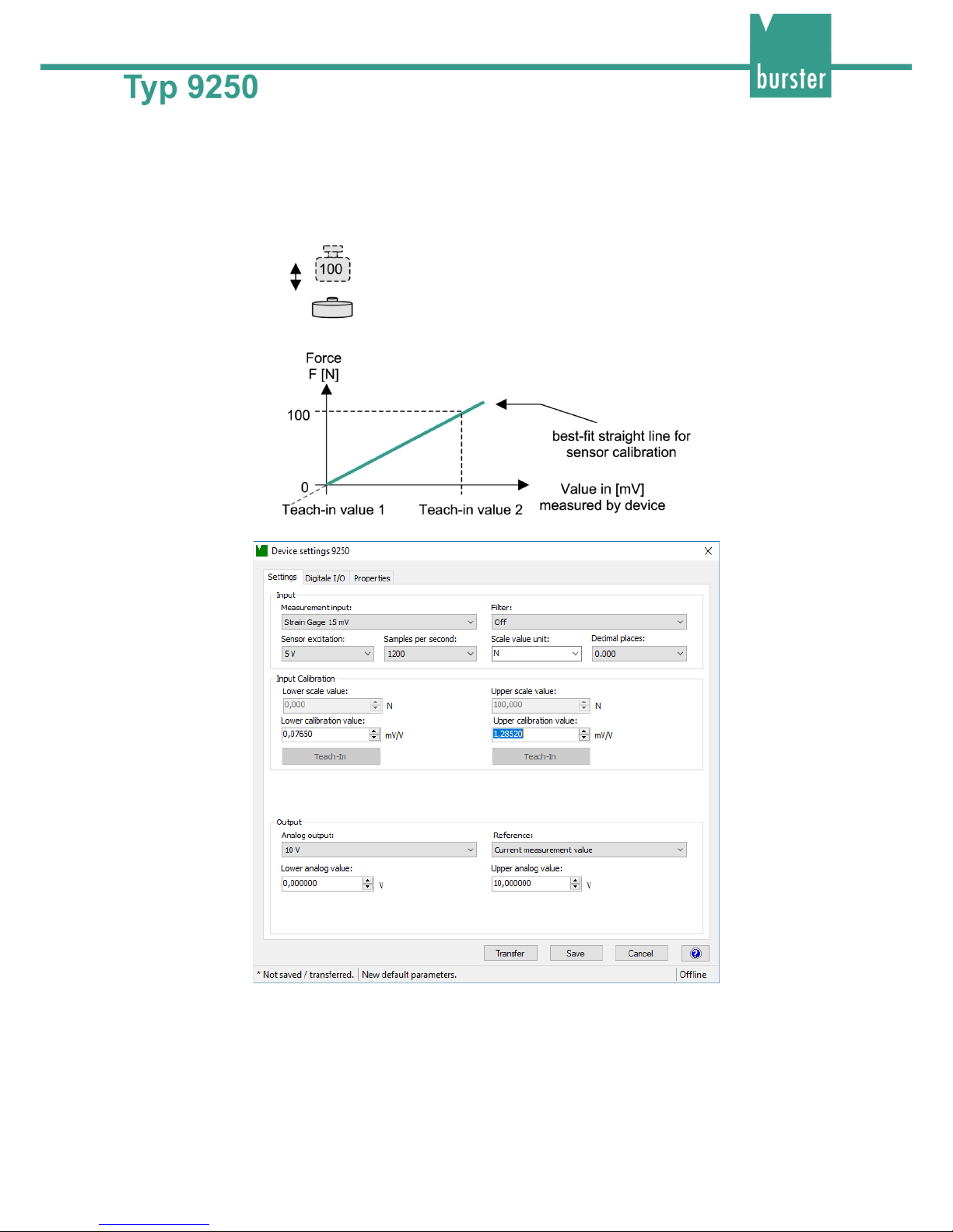
The teach-in method involves two-stage online "training" of the 9250 instrumentation amplifier using
sensor data, in which two teach-in states are applied sequentially. The first teach-in state is the zero point
under no load (lower scale value or lower analog value), and the second teach-in state is the upper limit
(upper scale value or upper analog value).
Diagram: 22 Characteristic sensor curve
Diagram: 23 Device settings 9250
Page 44
44 of 67
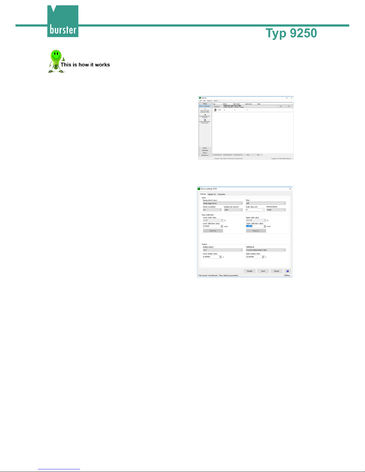
1 Start the DigiVision configuration and analysis software and make sure that the 9250
instrumentation amplifier is connected correctly and appears in the device list.
2 Click in the left-hand menu bar on "Import
parameters from device (online)". The
DigiVision configuration and analysis software
will then import the parameter data held in the
9250 instrumentation amplifier for the straingage sensor.
It is this strain-gage parameter data that can
now be obtained by the teach-in procedure.
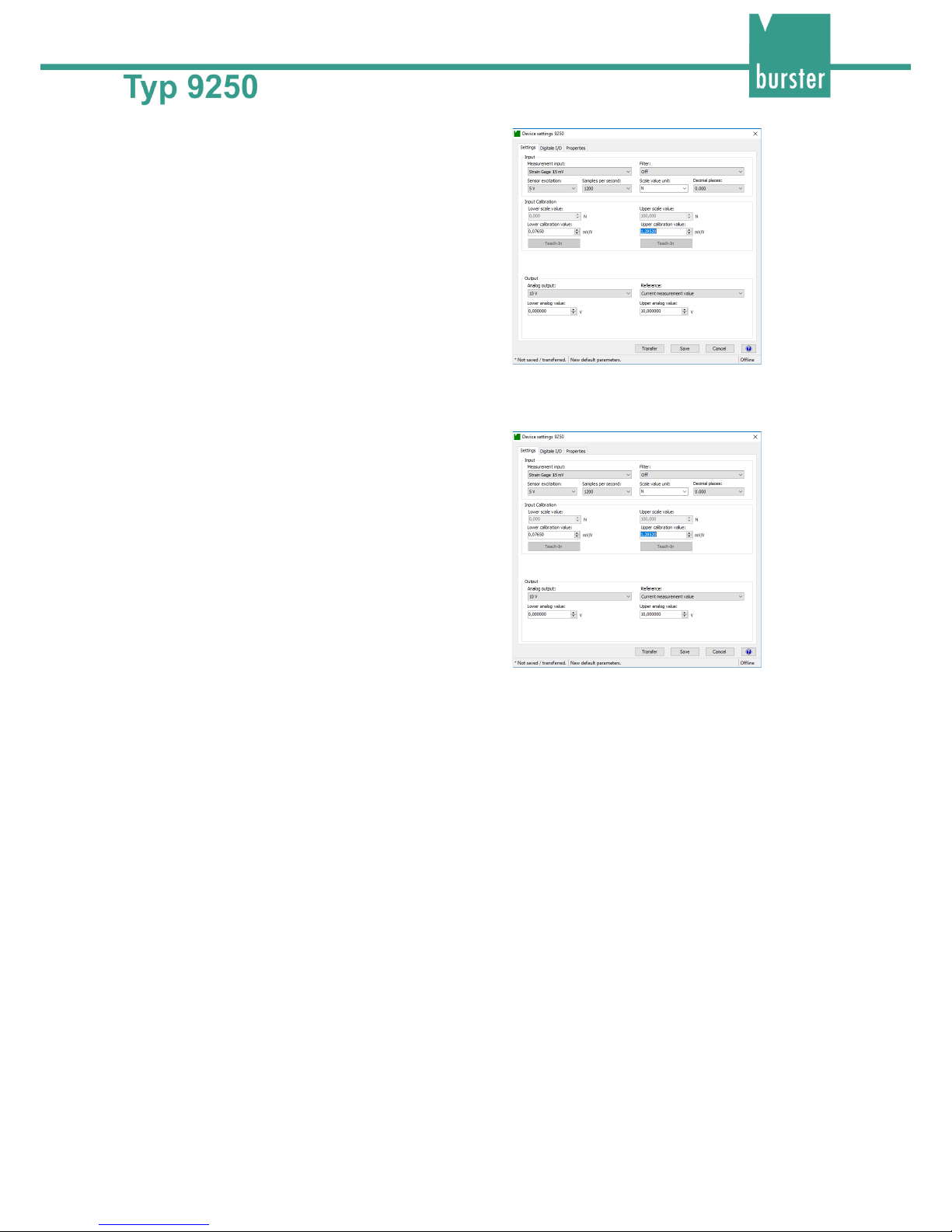
3 Remove any load from the strain-gage sensor and adjust the zero point F = 0 N (lower
scale value or lower analog value).
4 Enter the lower scale value or lower analog
value of the measuring range for the straingage sensor. This is normally "0".
5 Then click the [Teach-In] button under "Lower calibration value” and confirm with "OK".
The lower calibration value appears in the field (e.g. 0.0765).
The lower calibration value is the electrical signal from the strain-gage sensor under
the "load" given by the lower scale value or lower analog value (usually the zero point
of the strain-gage sensor).
Note: The option to adjust the scale value is only available for the bus model.
Note: The zero point of a strain-gage sensor may shift from the origin as a result of the
way the sensor is mounted (load application components, couplings, adapters etc.,
which themselves can exert a pre-load) or material aging. This means that the
electrical value specified under "Zero output" in the test and calibration certificate for
the strain-gage sensor will differ from the measured zero point. This is why we
recommend always using the teach-in process to set the zero point of the strain-
gage sensor.
Page 45
45 of 67
6 Enter the upper scale value or upper
analog value of the measuring range for
the strain-gage sensor. For load cells, this
is usually the rated load of the sensor. In
our example the rated load (nominal
force) equals 100 N.
7 Then apply a known reference load to the strain-gage sensor
e.g. F = 100 N (upper scale value or upper analog value) to set the upper limit.
8 Then click the [Teach-In] button under
"Upper calibration value” and confirm with
"OK".
9 Click "Transfer". This completes the teach-in method.
10 If you wish, you can also save the parameter data for the strain-gage sensor in a file.
Page 46
46 of 67
7.1.2 Adjustment using the test and calibration certificate
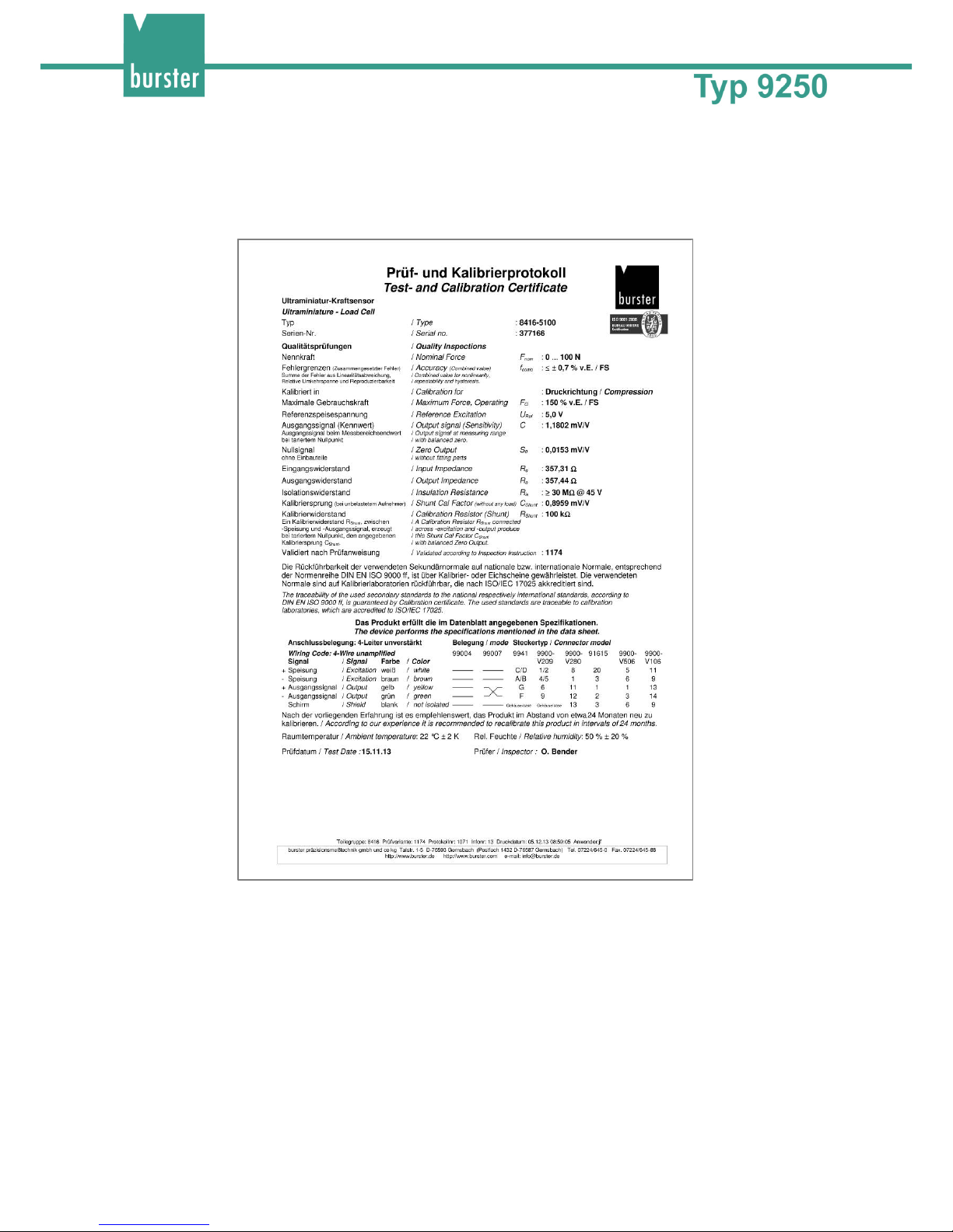
This method involves a two-point calibration in which you enter the necessary data directly in the 9250
instrumentation amplifier. You can obtain all the necessary rescaling data from the test and calibration
certificate for the strain-gage sensor.
Diagram: 24 Test and calibration certificate for a strain-gage sensor (specimen)
Page 47
47 of 67
With two-point calibration you enter two points in succession. The first point, for example, is the zero point
under no load (lower scale value or lower analog value), and the second point is the upper limit (upper
scale value or upper analog value).
Note: It need not necessarily be the zero point and upper limit; in theory any two value pairs will do.
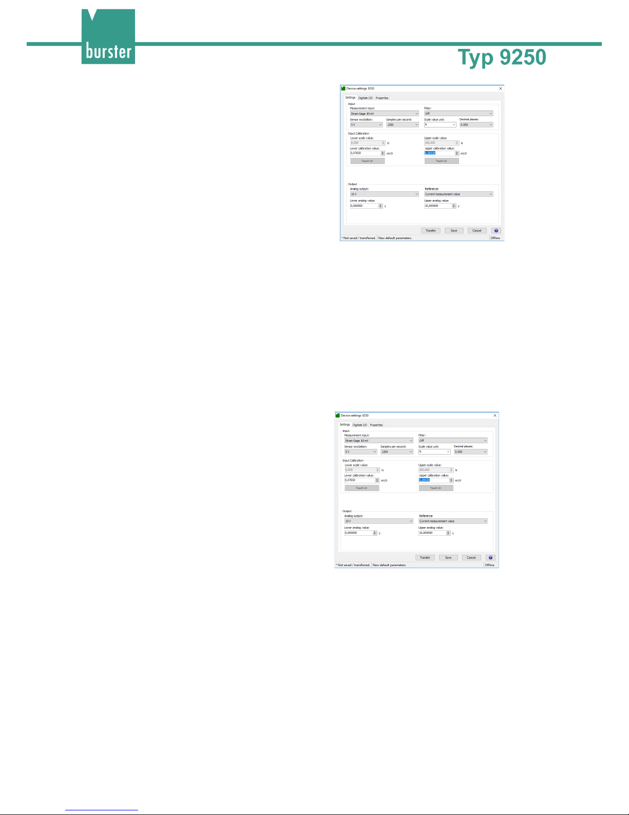
Diagram: 25 Device settings 9250
1 Start the DigiVision configuration and analysis software and make sure that the 9250
instrumentation amplifier is connected correctly and appears in the device list.
2 Click in the left-hand menu bar on "Import
parameters from device (online)". The
DigiVision configuration and analysis software
will then import the parameter data held in the
9250 instrumentation amplifier for the straingage sensor.
The strain-gage parameter data can be
entered here.
3 Remove any load from the strain-gage sensor and adjust the zero point F = 0 N (lower
scale value or lower analog value).
Page 48
48 of 67
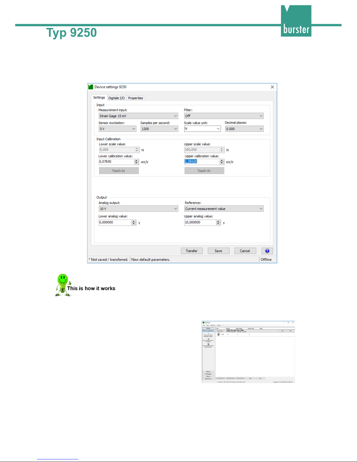
4 Enter the lower scale value or lower analog
value of the measuring range for the straingage sensor. This is normally "0".
5 Then click the [Teach-In] button under "Lower calibration value” and confirm with "OK".
The lower calibration value appears in the field (e.g. 0.0765).
The lower calibration value is the electrical signal from the strain-gage sensor under
the "load" given by the lower scale value or lower analog value (usually the zero point
of the strain-gage sensor).
Note: The option to adjust the scale value is only available for the bus model.
Note: The zero point of a strain-gage sensor may shift from the origin as a result of the
way the sensor is mounted (load application components, couplings, adapters etc.,
which themselves can exert a pre-load) or material aging. This means that the
electrical value specified under "Zero output" in the test certificate for the straingage sensor will differ from the measured zero point. This is why we recommend
always using the teach-in process to set the zero point of the strain-gage sensor.
6 Enter the upper scale value or upper
analog value of the measuring range for
the strain-gage sensor. For load cells, this
is usually the rated load of the sensor. In
our example the rated load (nominal
force) equals 100 N.
7 Now you need to enter a corrected value for the rated output of the strain-gage sensor
in the preferential measurement direction. Add the teach-in value for the lower
calibration value (0.0765 in our example) to the full-scale output of the strain-gage
sensor.
The full-scale output for the strain-gage sensor is given in the test and calibration
certificate under Output signal (e.g. 1.1802). Type in the corrected value
(1.1802 + 0.0765 = 1.2567) under "Upper calibration value".
8 Click "Transfer". This completes the adjustment using the test and calibration
certificate.
9 If you wish, you can also save the parameter data for the strain-gage sensor in a file.
Page 49
49 of 67
7.2 Adjustment with potentiometric displacement sensors
using the teach-in method
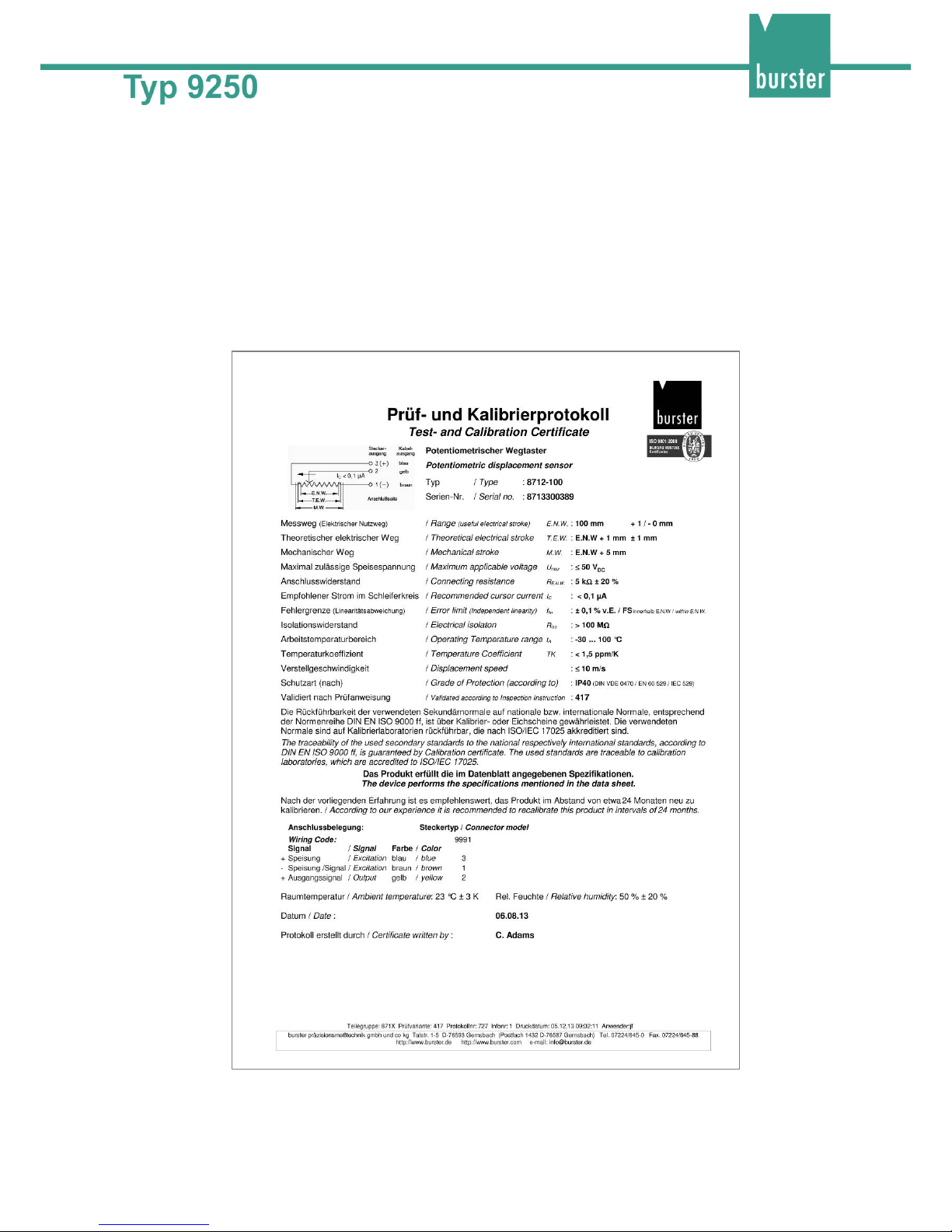
The teach-in method involves two-stage online "training" of the 9250 instrumentation amplifier using
sensor data, in which two teach-in states are applied sequentially. The first teach-in state is the zero point
under no load (lower scale value or lower analog value), and the second teach-in state is the upper limit
(upper scale value or upper analog value). You can obtain all the necessary adjustment data from the test
and calibration certificate for the potentiometric displacement sensor.
Measurements using a calibrated gage block have proved to be the most straightforward and practical
way of adjustment systems that measure position and length (such as potentiometric displacement
sensors). Potentiometric angular position sensors can also be connected.
Diagram: 26 Test and calibration certificate for a potentiometric displacement sensor (specimen)
Page 50
50 of 67
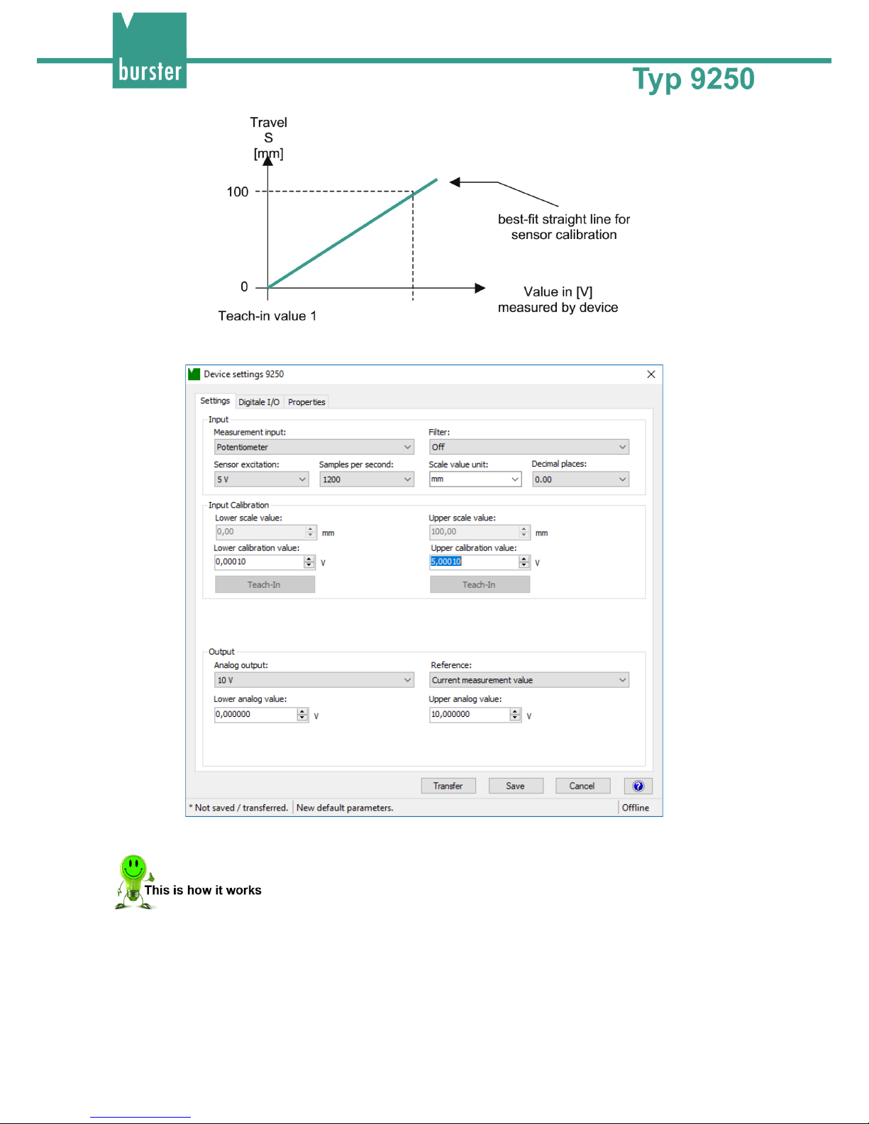
Diagram: 27 Characteristic sensor curve
Diagram: 28 Device settings 9250
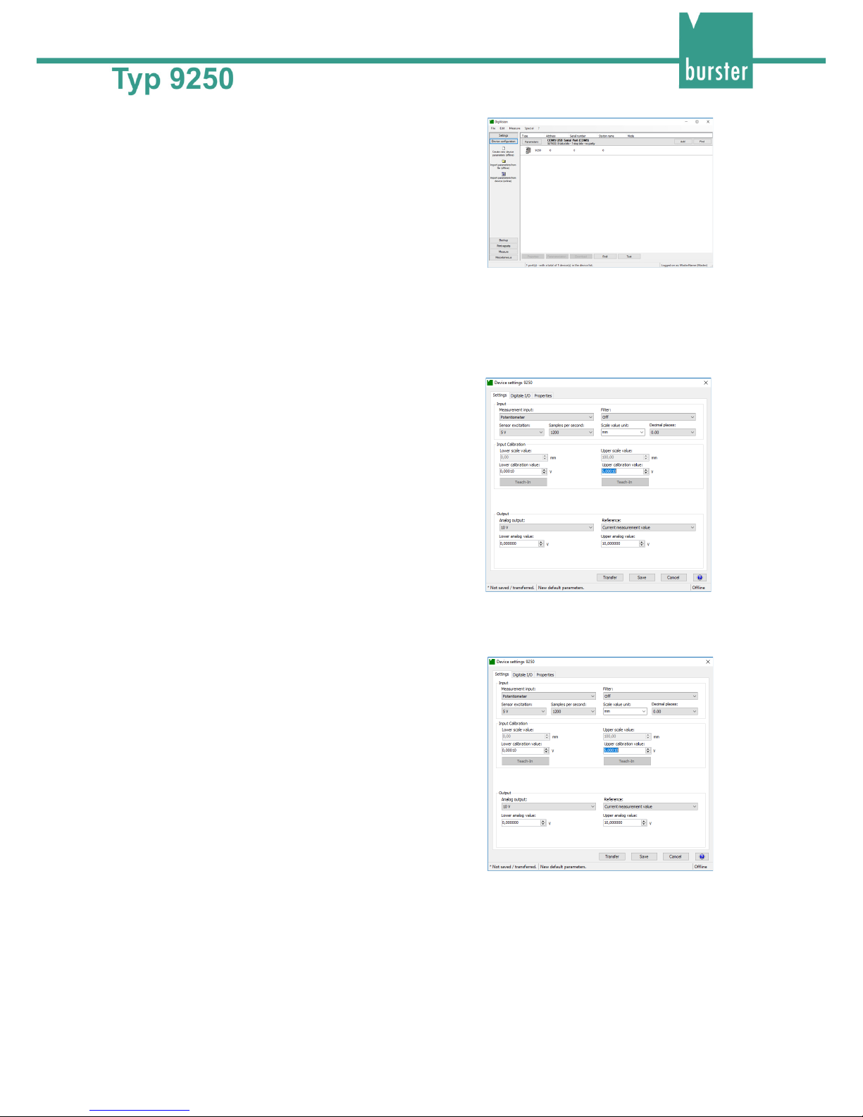
1 Start the DigiVision configuration and analysis software and make sure that the 9250
instrumentation amplifier is connected correctly and appears in the device list.
Page 51
51 of 67
2 Click in the left-hand menu bar on "Import
parameters from device (online)". The
DigiVision configuration and analysis software
will then import the parameter data held in the
9250 instrumentation amplifier for the
potentiometric displacement sensor.
It is this parameter data for the potentiometric
displacement sensor that can now be obtained
by the teach-in procedure.
3 Position measurement using the example of a potentiometric displacement sensor of
type 8712-100:
Set the potentiometric displacement sensor to the zero position (0.00 mm). Usually this
is when the sliding shaft of the sensor is fully pushed in, but there may be slight
differences between the mechanical and electrical zero points.
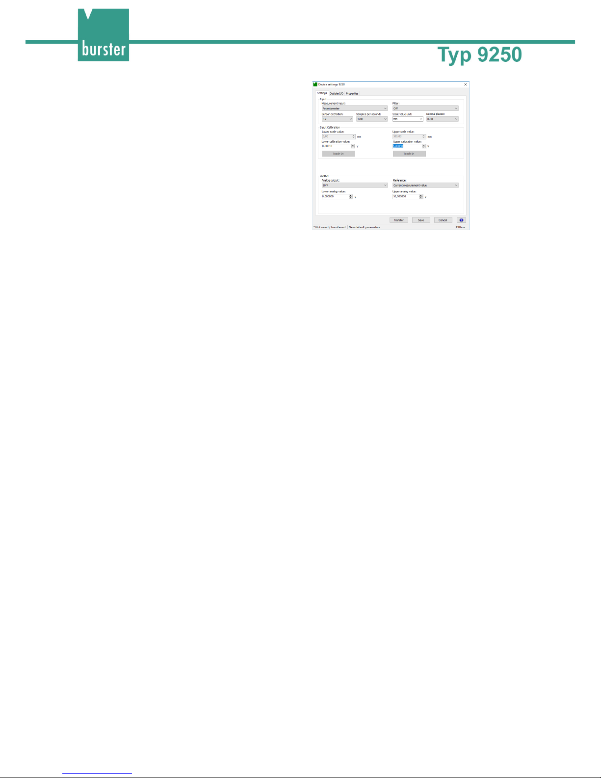
4 Enter the lower scale value or lower analog
value of the measuring range for the
potentiometric displacement sensor. Usually
this is the lower range value of the sensor, e.g.
0.00 mm.
5 Then click the [Teach-In] button under "Lower calibration value” and confirm with "OK".
The lower calibration value appears in the field.
6 Enter the upper scale value or upper
analog value of the measuring range for
the potentiometric displacement sensor,
for instance 100.00 mm.
7 Now move the sliding shaft using a calibrated gage block to s = 100 mm to set the
upper scale value.
Page 52
52 of 67
8 Then click the [Teach-In] button under
"Upper calibration value” and confirm with
"OK". In our example we have specified
"2" decimal places.
9 Click "Transfer". This completes the teach-in method.
10 If you wish, you can also save the parameter data for the potentiometric displacement
sensor in a file.
Note: The option to adjust the scale value and set the number of decimal places is only available for
the bus model.
Note: The maximum permitted sensor excitation voltage for the potentiometric displacement sensors
is given in the test and calibration certificate. To enable practical measurements, choose the 5 V
excitation voltage. The maximum measurement signal output from potentiometric displacement
sensors is always the excitation voltage.
Page 53
53 of 67
7.3 Adjustment with transmitters or sensors having a
standard signal output
7.3.1 Adjustment with transmitters with voltage output by the
teach-in method
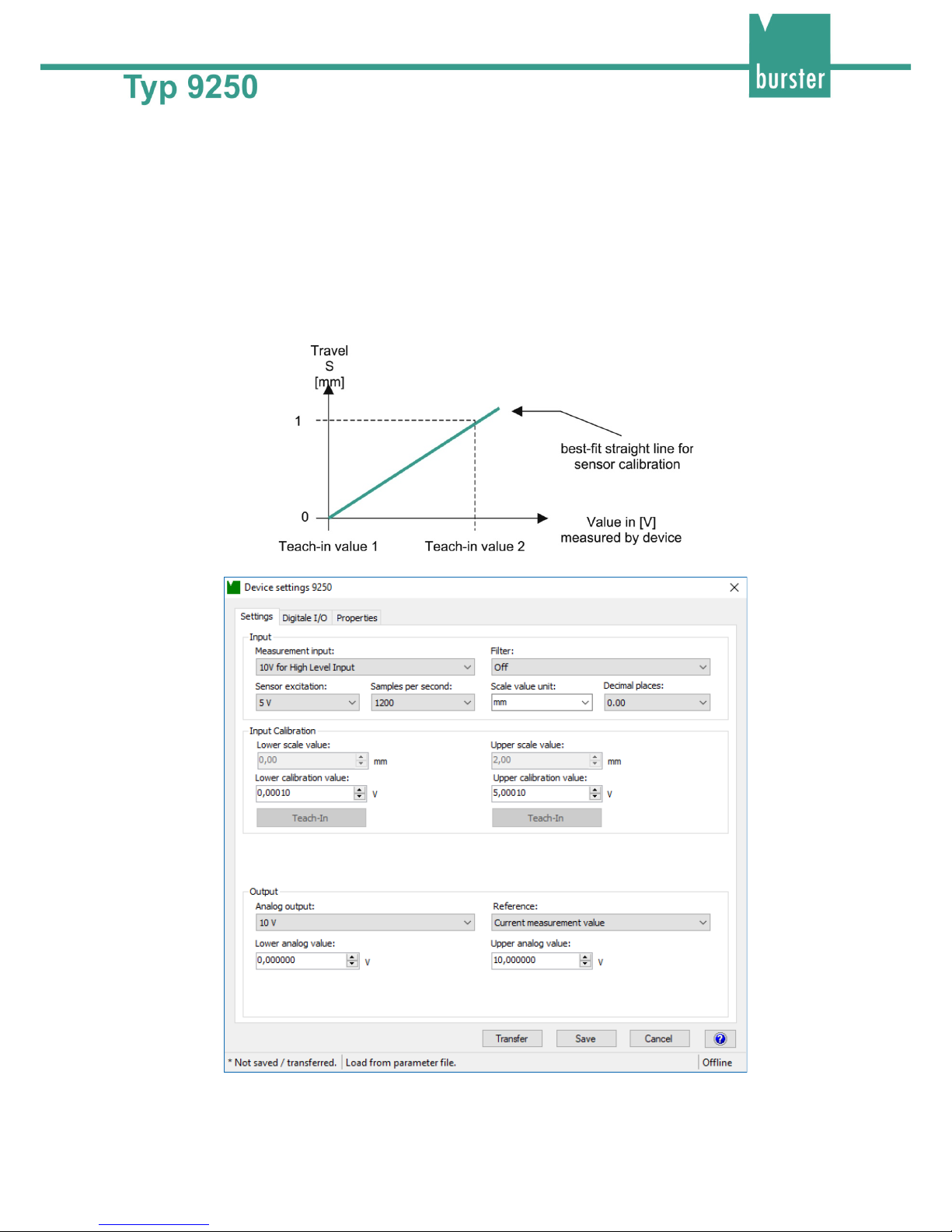
The teach-in method involves two-stage online "training" of the 9250 instrumentation amplifier using
sensor data, in which two teach-in states are applied sequentially. The first teach-in state is the zero point
under no load (lower scale value or lower analog value), and the second teach-in state is the upper limit
(upper scale value or upper analog value).
Diagram: 29 Characteristic sensor curve
Diagram: 30 Device settings 9250
Page 54
54 of 67
1 Start the DigiVision configuration and analysis software and make sure that the 9250
instrumentation amplifier is connected correctly and appears in the device list.
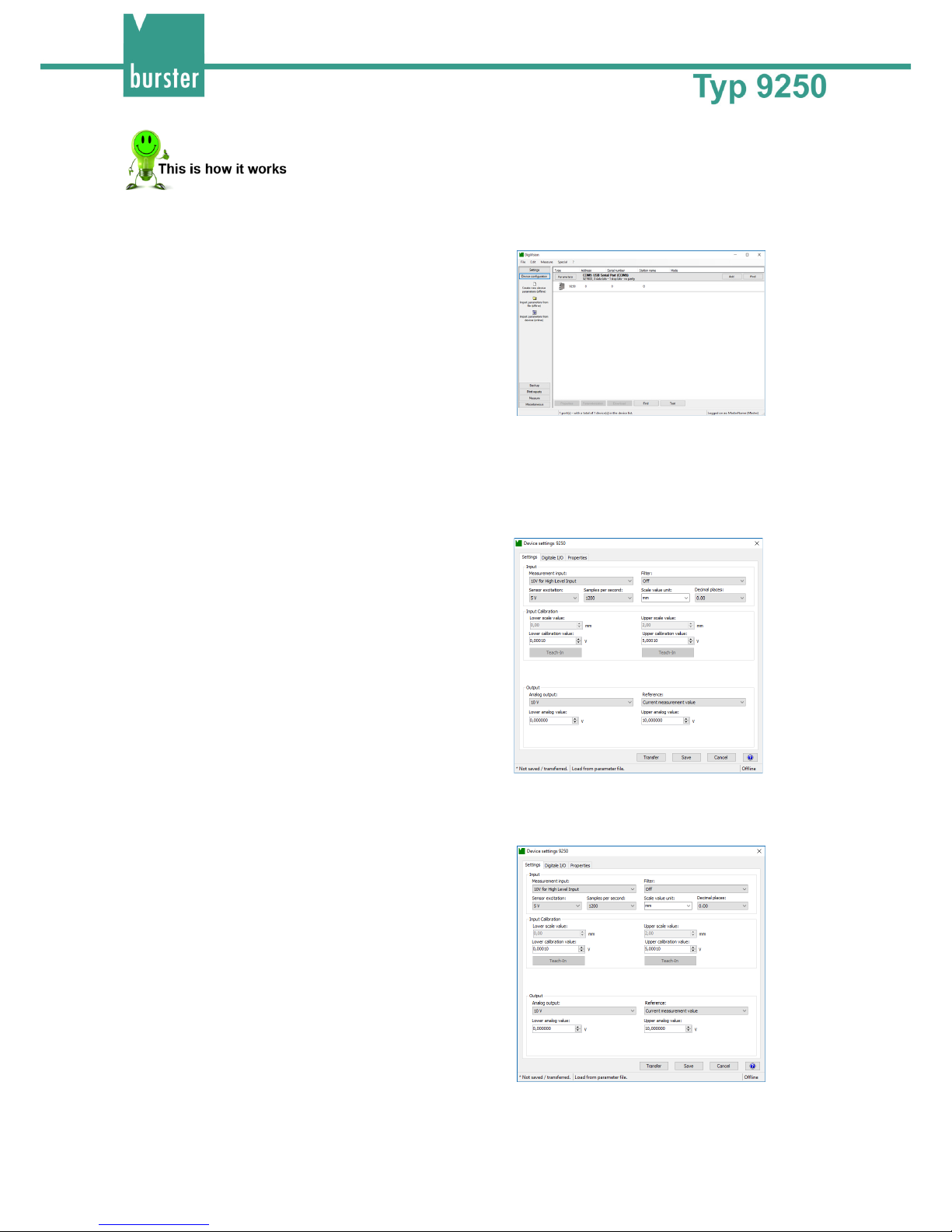
2 Click in the left-hand menu bar on "Import
parameters from device (online)". The
DigiVision configuration and analysis software
will then import the sensor parameter data held
in the 9250 instrumentation amplifier.
It is this sensor parameter data that can now
be obtained by the teach-in procedure.
3 Position measurement using the example of an inductive displacement transducer of
type 8740-5001:
Set the displacement transducer to the zero position (0.00 mm). Usually this is when
the sliding shaft of the sensor is fully extended, but there may be slight differences
between the mechanical and electrical zero points.
4 Enter the lower scale value or lower analog
value of the measuring range for the inductive
displacement transducer. Usually this is the
lower range value of the sensor, e.g. 0.00 mm.
5 Then click the [Teach-In] button under "Lower calibration value” and confirm with "OK".
The lower calibration value appears in the field.
6 Enter the upper scale value or upper
analog value of the measuring range for
the inductive displacement transducer, for
instance 2.00 mm.
Page 55
55 of 67
7 Now move the sliding shaft using a calibrated gage block to s = 2.00 mm to set the
upper scale value.
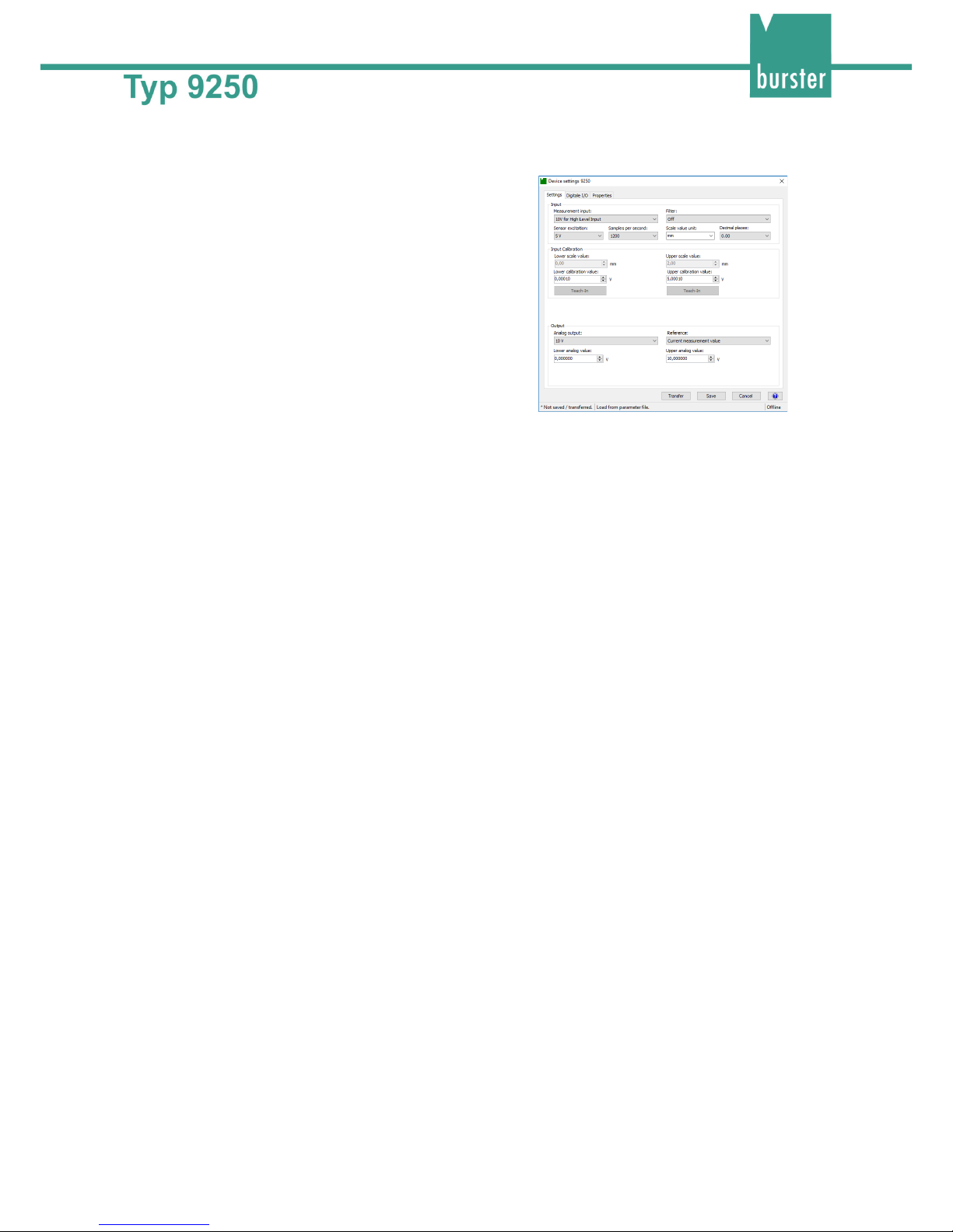
8 Then click the [Teach-In] button under
"Upper calibration value” and confirm with
"OK". In our example we have specified
"2" decimal places.
9 Click "Transfer". This completes the teach-in method.
10 If you wish, you can also save the sensor parameter data in a file.
Note: The option to adjust the scale value and set the number of decimal places is only available for
the bus model.
Page 56
56 of 67
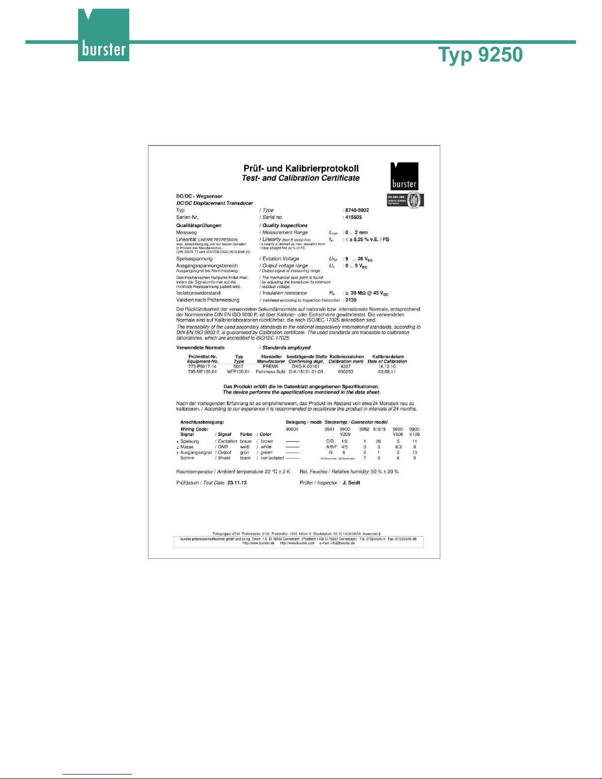
7.3.2 Rescaling using the test and calibration certificate
This method involves a two-point calibration in which you enter the necessary data directly in the 9250
instrumentation amplifier. You can obtain all the necessary rescaling data from the test and calibration
certificate for the transmitter or sensor with standard-signal output.
Diagram: 31 Test and calibration certificate (sample)
Page 57
57 of 67
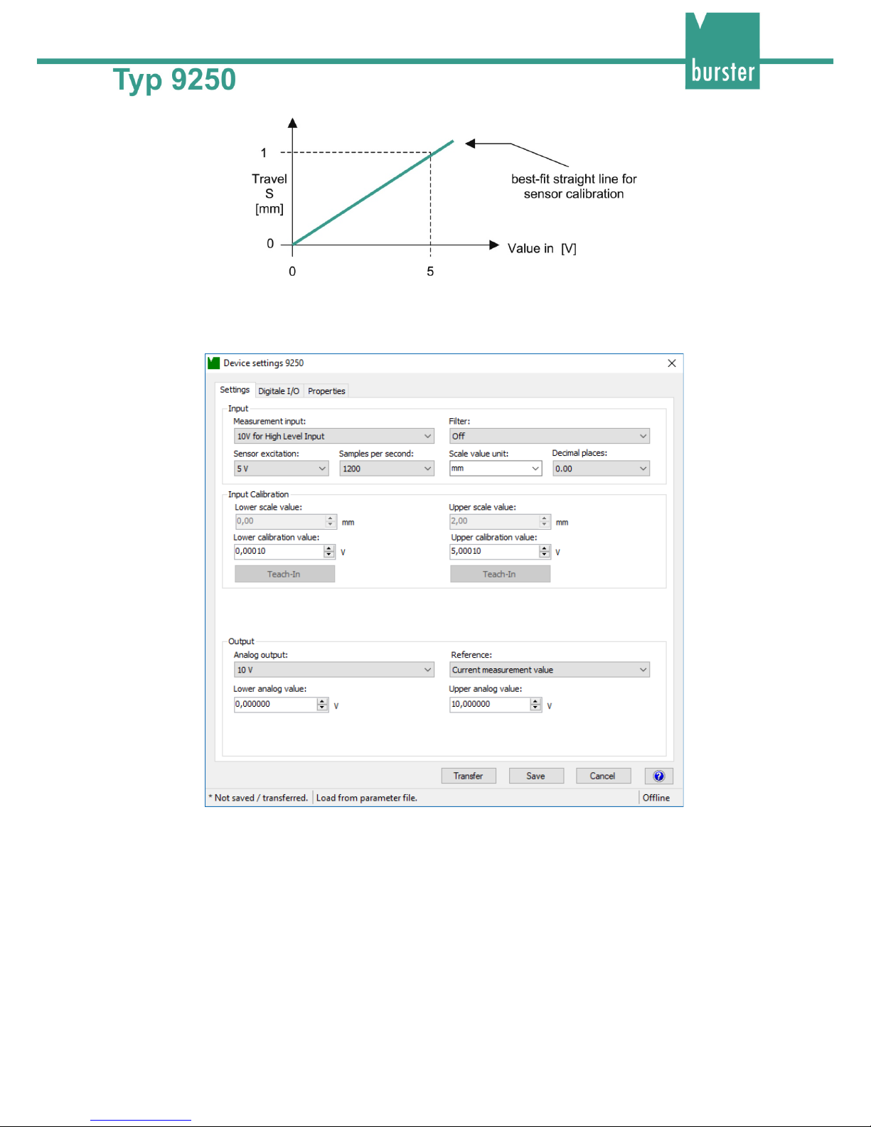
Diagram: 32 Characteristic sensor curve
With two-point calibration you enter two points in succession. The first point is the zero point under no
load (lower scale value or lower analog value), and the second point is the upper limit (upper scale value
or upper analog value).
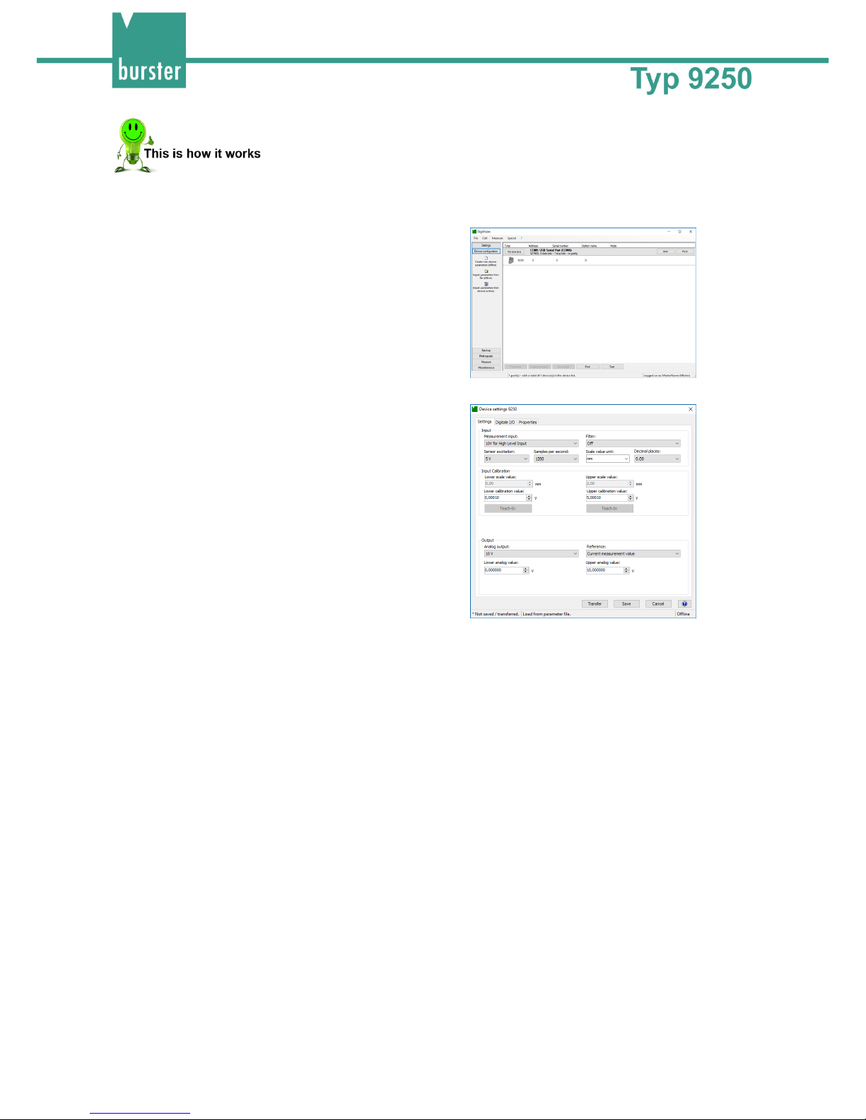
Diagram: 33 Device settings 9250
The adjustment was performed as follows:
Output voltage range of 0 ... 10 V ≡ measured displacement 0 ... 2 mm.
This adjustment data must now be transferred to the 9250 instrumentation amplifier; if required it can also
be saved.
Page 58
58 of 67
1 Start the DigiVision configuration and analysis software and make sure that the 9250
instrumentation amplifier is connected correctly and appears in the device list.
2 Click in the left-hand menu bar on "Import
parameters from device (online)". The
DigiVision configuration and analysis software
will then import the sensor parameter data held
in the 9250 instrumentation amplifier.
The sensor parameter data can be entered
here.
3 Enter the Lower scale value, the Lower
calibration value, the Upper scale value and
the Upper calibration value from the test and
calibration report for the sensor.
Note: The option to adjust the scale value is only available for the bus model.
4 Click "Transfer". This completes the adjustment using the test and calibration
certificate.
5 If you wish, you can also save the sensor parameter data in a file.
Page 59
59 of 67
7.4 Adjustment of the counter input
The 9250 instrumentation amplifier optionally includes a 32-bit counter, which can be operated and
configured in 3 different modes.
7.4.1 Totalizing counter
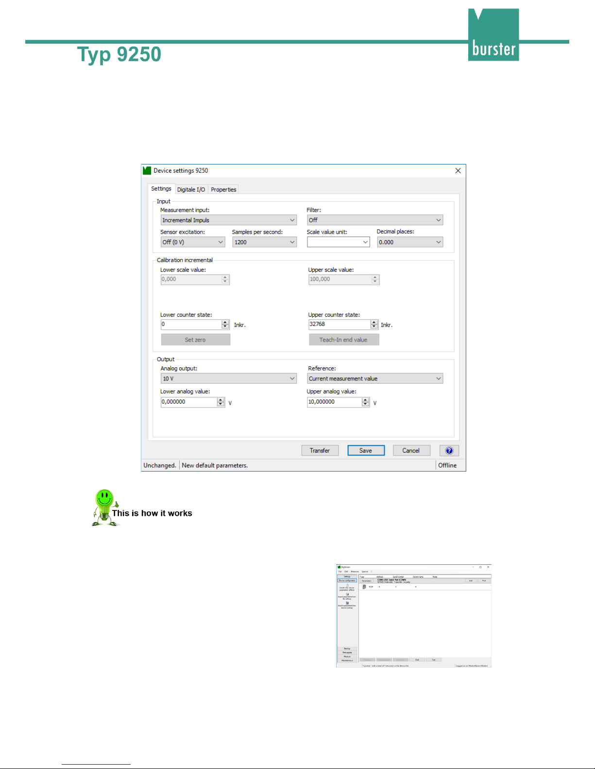
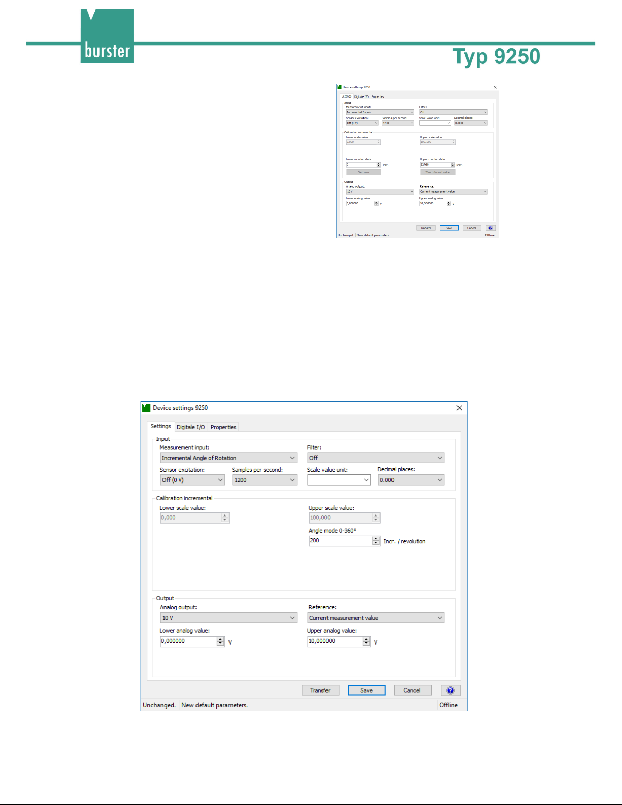
Diagram: 34 Device settings for the totalizing counter (Incremental Impuls mode)
1 Start the DigiVision configuration and analysis software and make sure that the 9250
instrumentation amplifier is connected correctly and appears in the device list.
2 Click in the left-hand menu bar on "Import
parameters from device (online)".
The parameter data can be entered here.
Page 60
60 of 67
3 Set the "Lower counter state" at which the
lower scale value or lower analog output is
output. This is usually 0.
4 Set the "Upper counter state" at which the upper scale value or upper analog output is
output. Alternatively, you can use the teach-in option to obtain this value. Click [Teach-
In end value] if you want to obtain the upper counter state by the teach-in method. The
decimal places have been set to "3" in our example.
5 Click "Transfer". This completes data entry.
6 If you wish, you can also save the parameter data in a file.
Note: The option to adjust the scale value and set the number of decimal places is only available for
the bus model.
7.4.2 360° angle of rotation
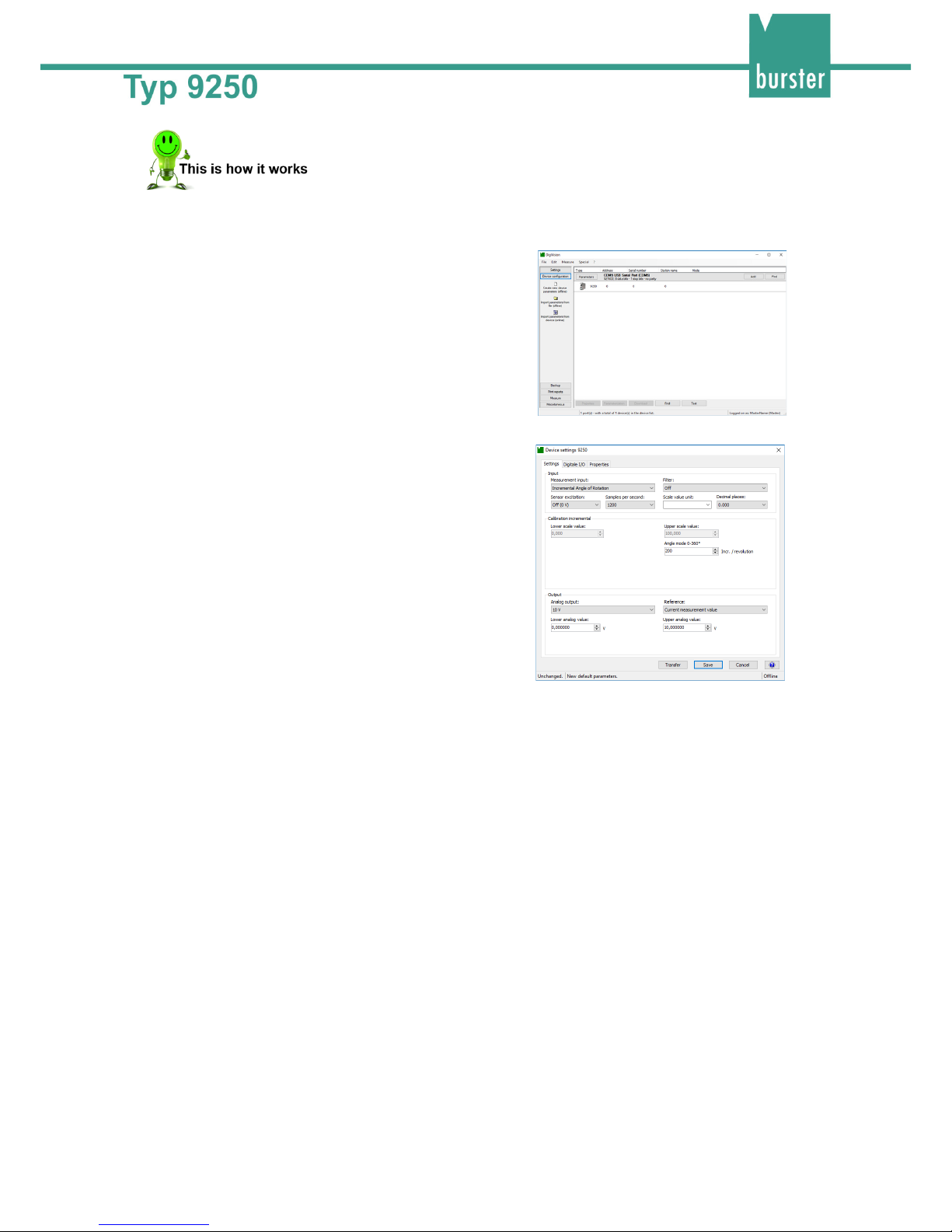
Diagram: 35 Device settings for 360° angle of rotation (Incremental Angle of Rotation mode)
Page 61
61 of 67
1 Start the DigiVision configuration and analysis software and make sure that the 9250
instrumentation amplifier is connected correctly and appears in the device list.
2 Click in the left-hand menu bar on "Import
parameters from device (online)".
The parameter data can be entered here.
3 Enter the number of increments per revolution
that your rotary encoder outputs.
4 Set the lower scale value or lower analog value, and the upper scale value or upper
analog value. The decimal places have been set to "3" in our example.
5 Click "Transfer". This completes data entry.
6 If you wish, you can also save the parameter data in a file.
Note: The option to adjust the scale value and set the number of decimal places is only available for
the bus model.
Page 62
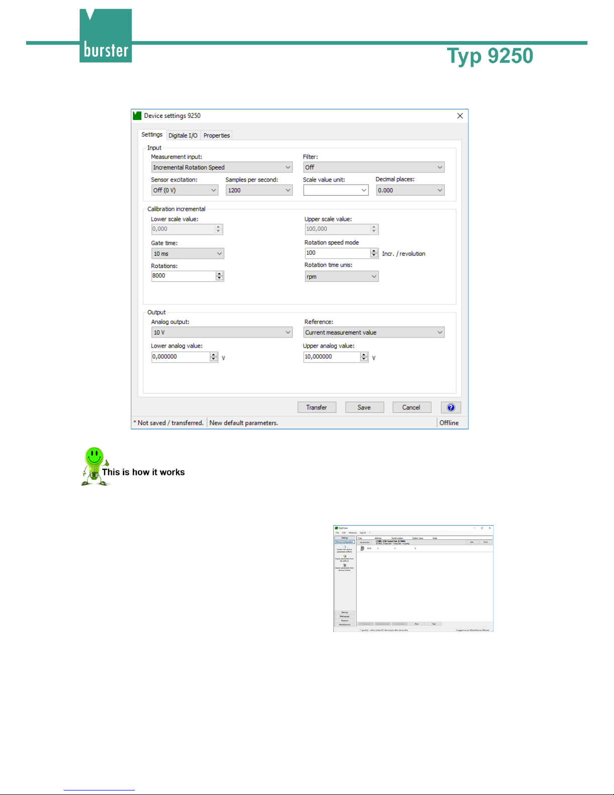
62 of 67
7.4.3 Rotational speed
Diagram: 36 Device settings for rotational speed (Incremental Angle of rotation mode)
1 Start the DigiVision configuration and analysis software and make sure that the 9250
instrumentation amplifier is connected correctly and appears in the device list.
2 Click in the left-hand menu bar on "Import
parameters from device (online)".
The parameter data can be entered here.
Page 63
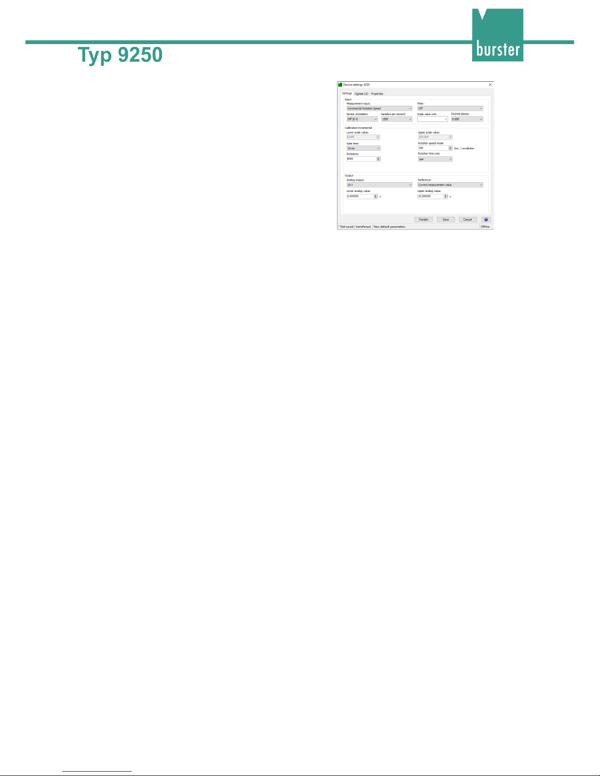
63 of 67
3 Enter the number of increments per revolution
that your rotary encoder outputs.
4 Set the lower scale value or lower analog value, and the upper scale value or upper
analog value. The decimal places have been set to "3" in our example.
5 Set the “Gate time” (the time over which counting is performed). A longer gate time
makes sense for slow speeds.
6 Specify whether the output is in revolutions/min or revolutions/s.
7 Click "Transfer". This completes data entry.
8 If you wish, you can also save the parameter data in a file.
Note: The option to adjust the scale value and set the number of decimal places is only available for
the bus model.
Page 64

64 of 67
8 Customer Services for your 9250 instrumentation
amplifier
To complement the 9250 instrumentation amplifier package you have purchased, burster
präzisionsmesstechnik gmbh & co kg offers the following customer services:
• On-site support for preparing the instrument for use
• Product training (in-house training at burster's premises or on-site training at customer's
premises)
• Initial calibration and recalibration, including sensors
To inquire about our customer services for your 9250 instrumentation amplifier, please telephone our
Service department on (+49) 07224-645-53, or email: [email protected]
(Germany only). If you are
outside Germany, you should contact your burster agent (see also www.burster.com).
Page 65
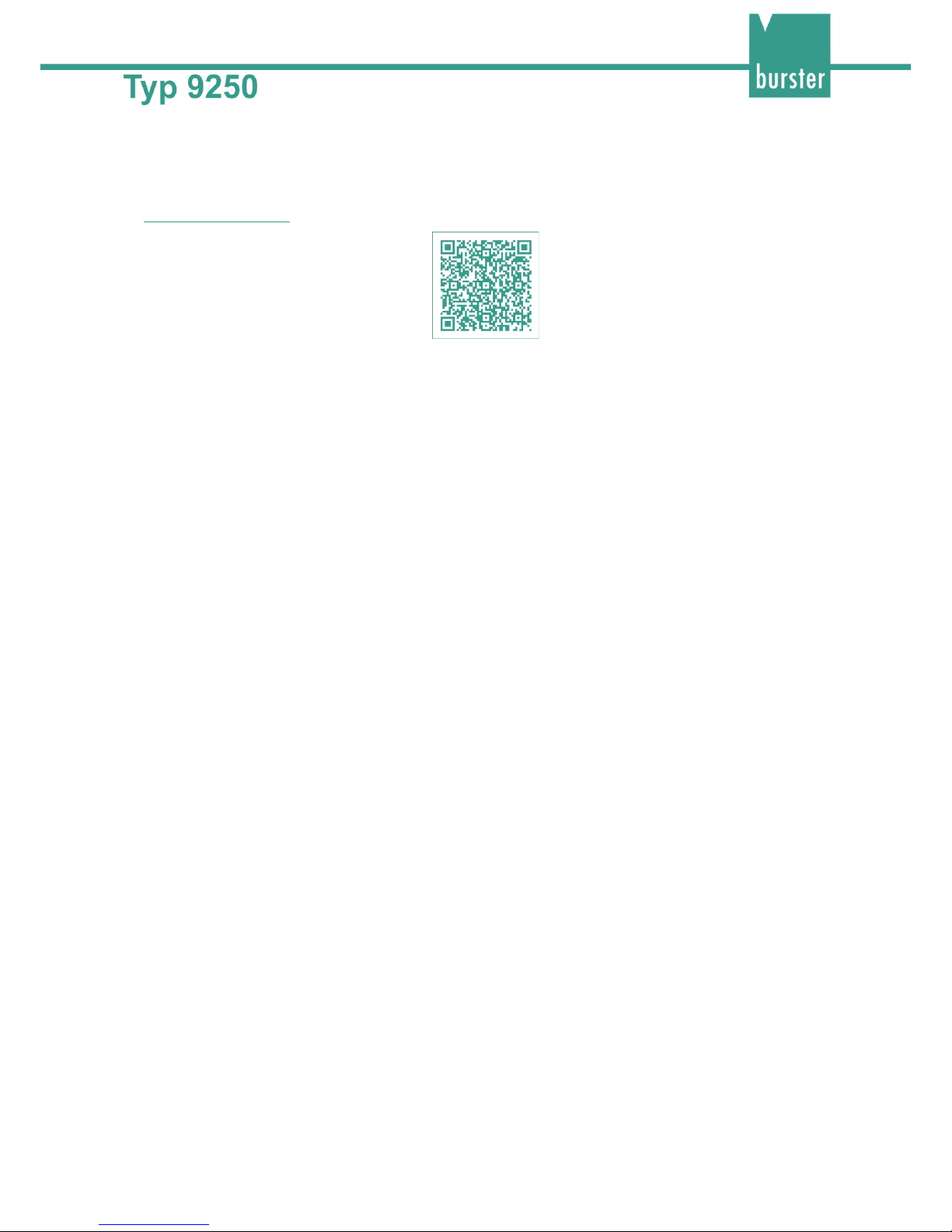
65 of 67
9 Technical data
The data sheet for the 9250 instrumentation amplifier contains the detailed technical specification. You
can obtain the latest data sheet and additional information on the 9250 instrumentation amplifier from
https://goo.gl/MQ27sG
or simply use the QR code below:
Diagram: 37 QR code for the 9250 instrumentation amplifier product page
9.1 Electromagnetic compatibility
9.1.1 Interference immunity
Interference immunity in compliance with EN 61326-1:2013
Industrial environment
9.1.2 Interference emission
Interference emission in compliance with EN 61326-1:2013
Page 66
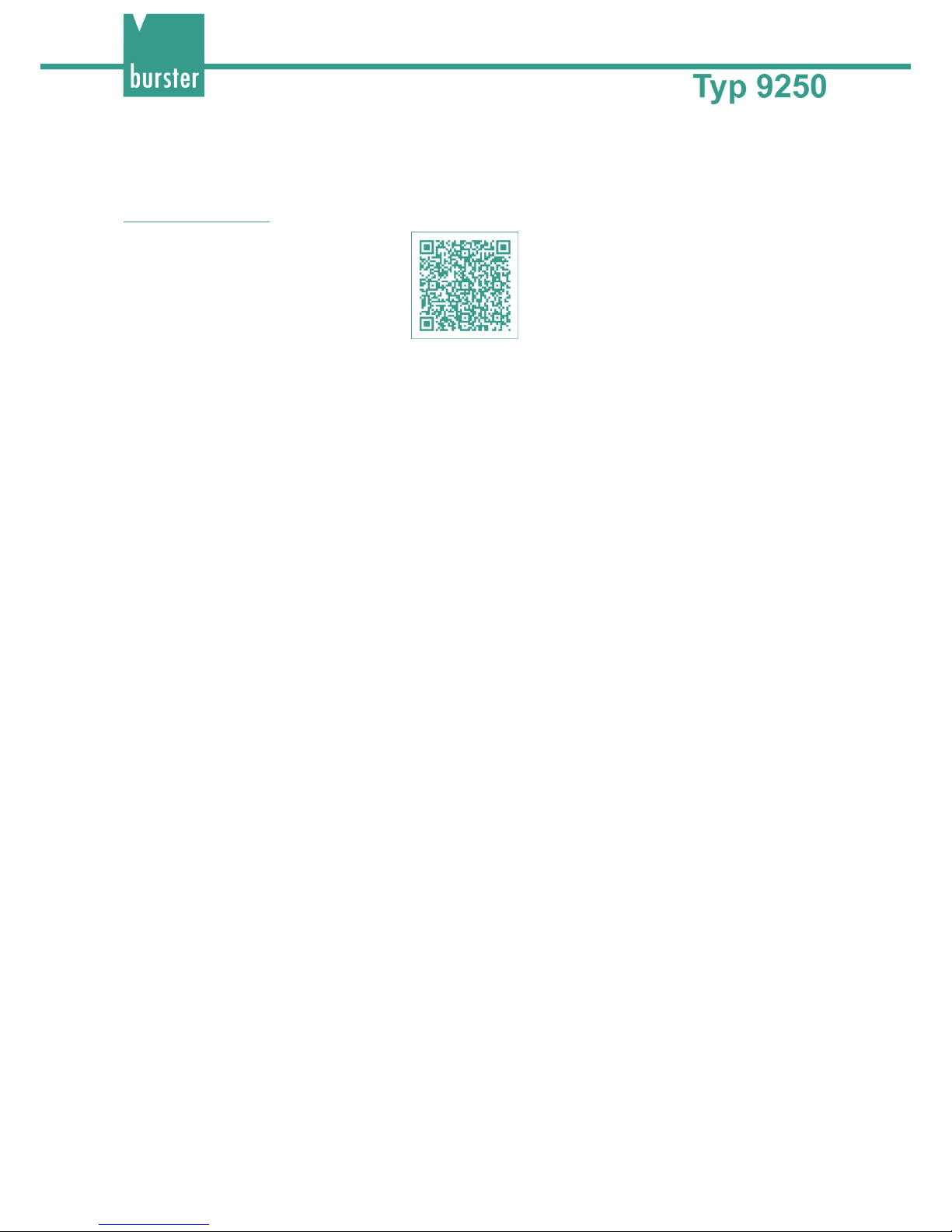
66 of 67
10 Accessories available
The data sheet for the 9250 instrumentation amplifier contains details of the accessories available. You
can obtain the latest data sheet and additional information on the 9250 instrumentation amplifier from
https://goo.gl/MQ27sG
or simply use the QR code below:
Diagram: 38 QR code for the 9250 instrumentation amplifier product page
Page 67
67 of 67
11 Disposal
Battery disposal
In Germany, the end user is legally obliged to return all used
batteries, and it is illegal to dispose of batteries in the household
waste. This law may also affect you as purchaser of the instrument
described here. Please dispose of your used batteries properly and in
accordance with national statutory regulations. Either take them to the
relevant collection point in your organization or to the collection points
provided by your local authority, our company or any battery retail
outlet.
Instrument disposal
If your instrument is no longer usable, please comply with your legal
obligations by disposing of the instrument described here in
accordance with statutory regulations. You will then be helping to
protect the environment!
 Loading...