

Page 1

Assembly Manual DIGNA
Seite 1
Foreword
Dear audio friend,
Thank you for purchasing this state-of-the-art phono preamp DIY kit. Y ou have purchased a
product that captivates as a DIY version a component quality and choice of materials that is
unique in the market and many industrially manufactured high-end products should attract
warm theirselves .
However, this also means that you should not "cobble together" this kit in record time. T ake a
quiet evening and about four hours time to build.
Also, you should already have the necessary equipment and knowledge to be able to build
such a high-quality DIY kit without complications. The resulting success will definitely reward
you for your effort and stamina.
The instructions assume electronic fundamentals, i.e. you already know that ICs, LEDs and
electrolytic capacitors are poled components and may not be soldered in reverse polarity.
Furthermore, the usage of a temperature-controlled soldering station with max. 1 mm wide
tip and correspondingly fine electronic solder as well as appropriate tools (multimeter, TX10
screwdriver, side cutter , tweezers, magnifying glass, etc.) are advised.
Please follow the steps and tips and hints in this manual. These are all tried out and
tested and allow you a trouble-free setup.
Important Safety Instructions
During installation, commissioning and measurements and repair special care is required!
Assembling of the circuit is at your own risk. The functionality can not be guaranteed, nor the
suitability for certain purposes. The user himself has to check this and is responsible for this
suitability . No liability can be accepted for damages arising during or as a result of the assembly
or operation, in particular for damages resulting from a lack of electronic skills.
The phono preamplifier may only be operated in a touch-proof housing in dry indoor enviroment.
Operation without or with defective tubes is not permitted!
The person who has completed a kit or has made an assembly ready by extension or encolure
installation, is according to VDE 0869 a manufacturer and therefore provided to supply all
documents when selling the device and also give his name and address. Devices which are
assembled from kits themselves are to be considered as an industrial product in terms of
safety.
And now, my friend - fire your soldering st ation now ...
Power Supply Board
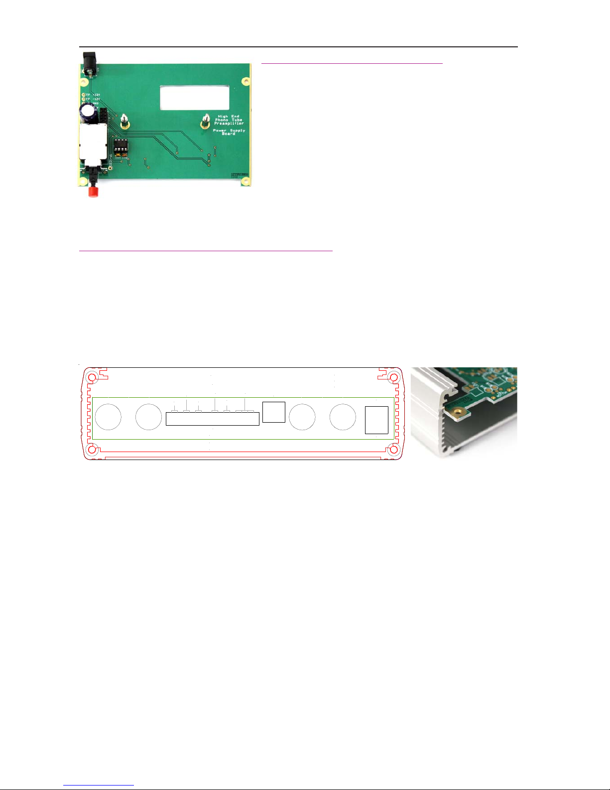
We'll start by assembling and checking the power supply board first. The SMD components
are already assembled and soldered on the solder side, so that our work is limited to the
assembly of the few through hole components and the two M3 x 13 spacers, which are fixed
from the solder side with two T orx screws M3 x 4.
Tip: Please solder only one pin of the 10-pin header BL1 first and align it exactly vertically.
Also, press the S3 switch all the way down to the PCB before soldering it. Also keep care
about the correct polarity of the 1000µF electrolytic capacitor .
Page 2
Assembly Manual DIGNA
Seite 2
Now check how the power supply
Connect the module to the supplied 12V power supply
and switch on. Now use a multimeter to measure the
voltage at the test points against TP GND:
A tolerance of 5% at the 12 V measuring points and
3% at the 64 V measuring point is in order .
If the voltages differ significantly more strongly, then
please check the assembly - also SMD - for any errors
or cold solder joints.
Do not continue as long as the power supply module does not work properly!
Now disconnect the 12V power supply and set aside the power supply module.
We will build an assembly aid for the mainboard
Pick up the black frame for the rear and the engraved silvery rear frame and peel off the
protective films. Carefully fit these two parts precisely to each other - note the drawing below
and that the rectangular cutout in the black frame has a greater distance at the top, but do not
yet press both parts firmly . Now take the black aluminium profile (a natural colored anodized
profile is used in this manual for the photos) and the four M3 x 10 T orx screws. Put the combined
rear frames on the profile and screw it tight. It might be that the U-profile is a little bit "bent" by
the casting process and you get it "in shape" by tighten the srews.
Next fit on the bottom of the aluminium profile the four black adhesive feet to the corners of the
large flat surface. Now slide the mainboard into the second groove from above as shown in
the picture.
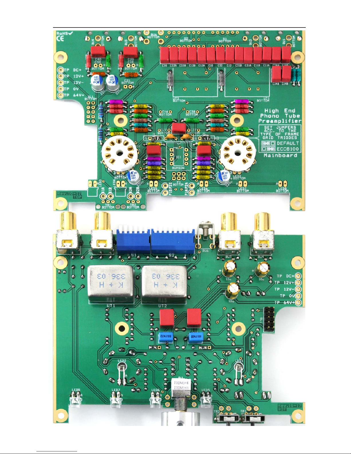
We will start by assembling the CFM55 resistors. As you've already noticed, these brown
audio-grade resistors do not have a color code, but the resistance value is printed directly in
plain text.
However, this requires that the resistors must be bent in the way before fitting, that
their value is still readable from upside.
Otherwise, a later (hopefully not necessary) troubleshooting is almost impossible!
Start with the most common values, here with the 330R resistors. For non-taped (loose)
resistors, cut 2 cm from the wires before assembling. The resistance values which are printed
on the board should help you to find them.
When inserted into the profile, you will not find R1 1 and R31 (49.9k each) because they are
hidden by the profile. Therefore, put these two resistors aside. Next, when assembly of the
resistors is finsihed, fit the two tube sockets by first soldering the two outer pads (pins 1 and
9) from components side for fixation. Then pull the module out of the profile and assemble the
two remaining resistors R1 1 / R31 at the top right edge, the red WIMA capacitors, the two
1µF ceramic capacitors, the four 220µF polymer electrolytic capacitors (please keep a gap
of 0.5 mm to the PCB) and the two jumpers Z1-Y1 or Z2-Y2 if you use the supplied ECC8100
tubes.
50p
R
100p
200p
MM
CAPACITANCE
50p DEFAULT + VALUE OF DIP-SWITCH SETTINGS
INPUT IMPEDANCE MM = 47k MC = VARIABLE ON FRONT
DIY PREAMP KIT CAREFULLY
DESIGNED AND ASSEMBLED
L IN
GND
RL OUT
PWR
12V 1A
INPUT SETTINGS
MC
GD
FOR MM GD MUST BE
set to ON
Do Not Open While Operational – No Servicing Parts Inside
IN GERMANY BY MR. NIXIE
Page 3
Assembly Manual DIGNA
Seite 3
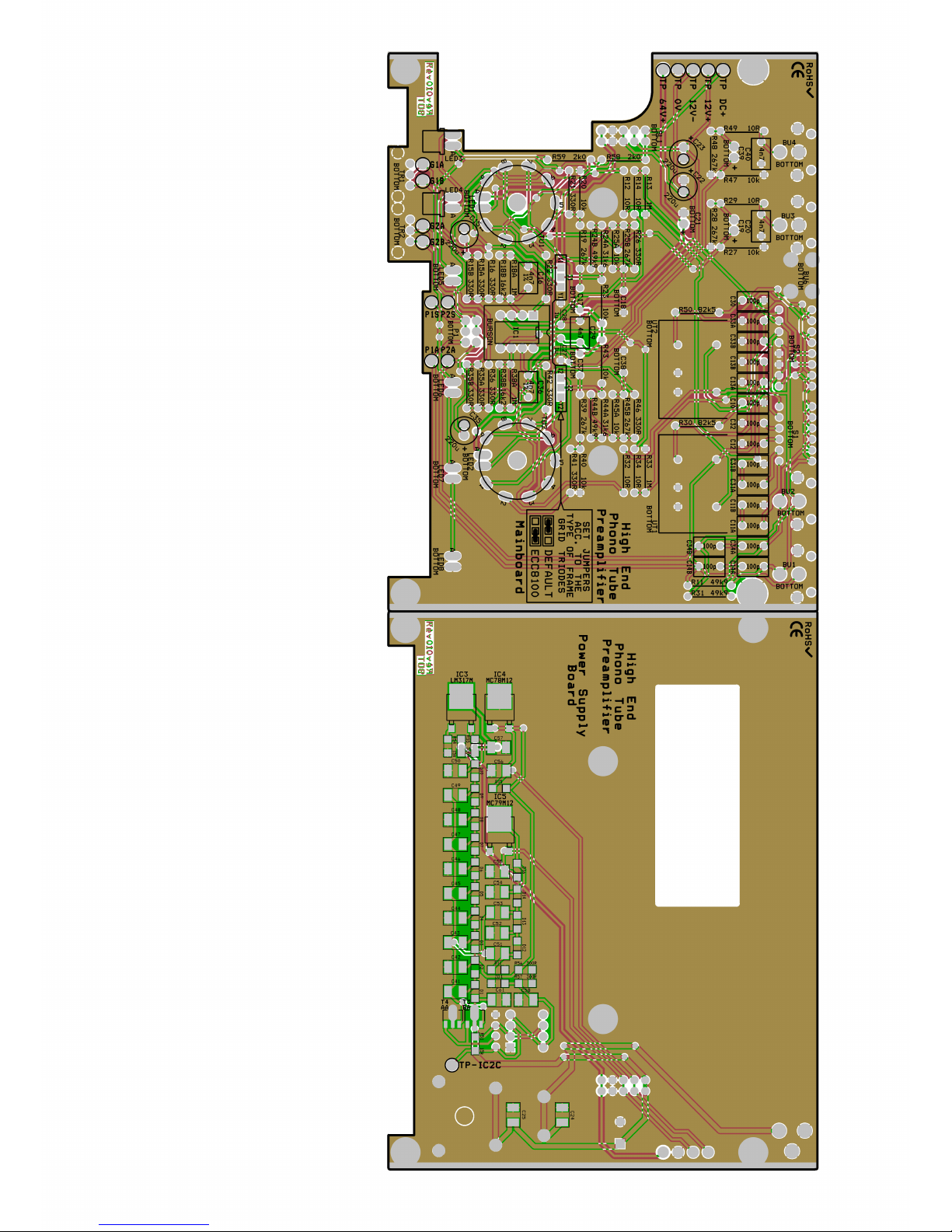
To better find the individual resistances on the PCB their
values are marked in different colors.
10 ohms
330 ohms
10 k
16.2 k
31.6 k
49.9 k
82.5 k
267 k
1 M
Page 4
Assembly Manual DIGNA
Seite 4
Parts assembly on solder side and mounting into the aluminium frame
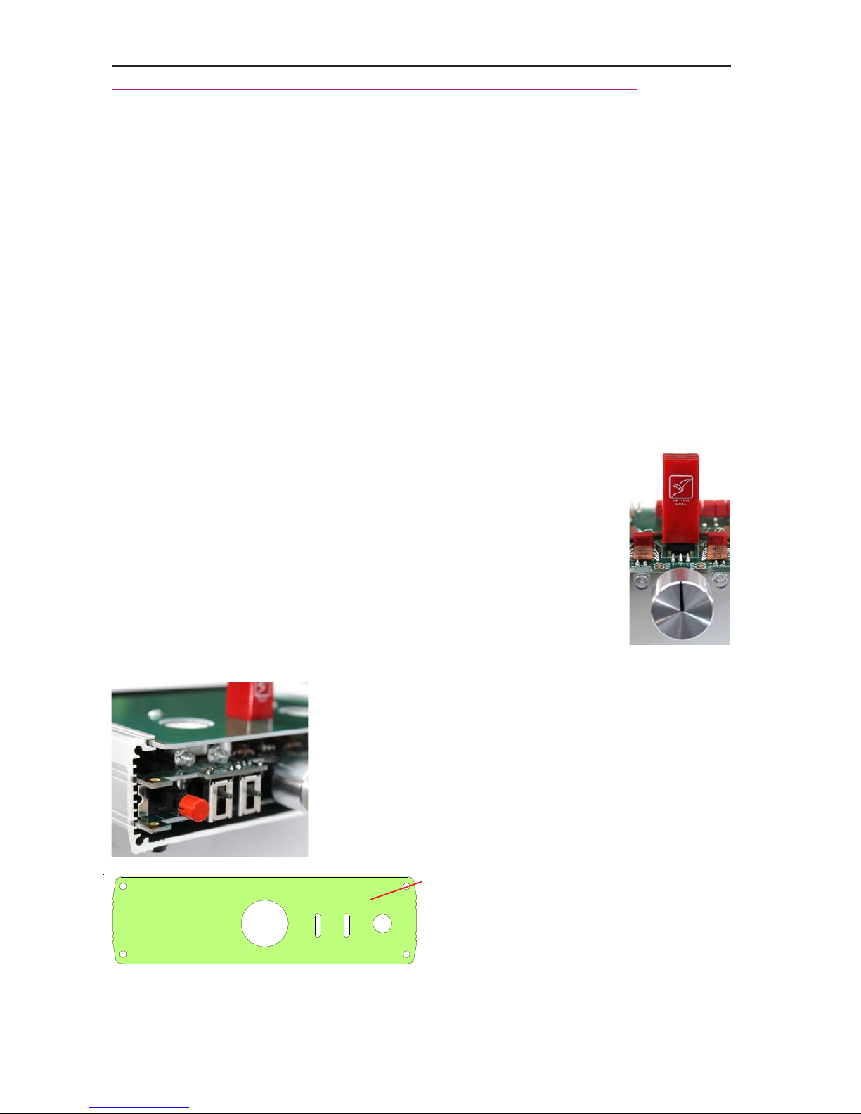
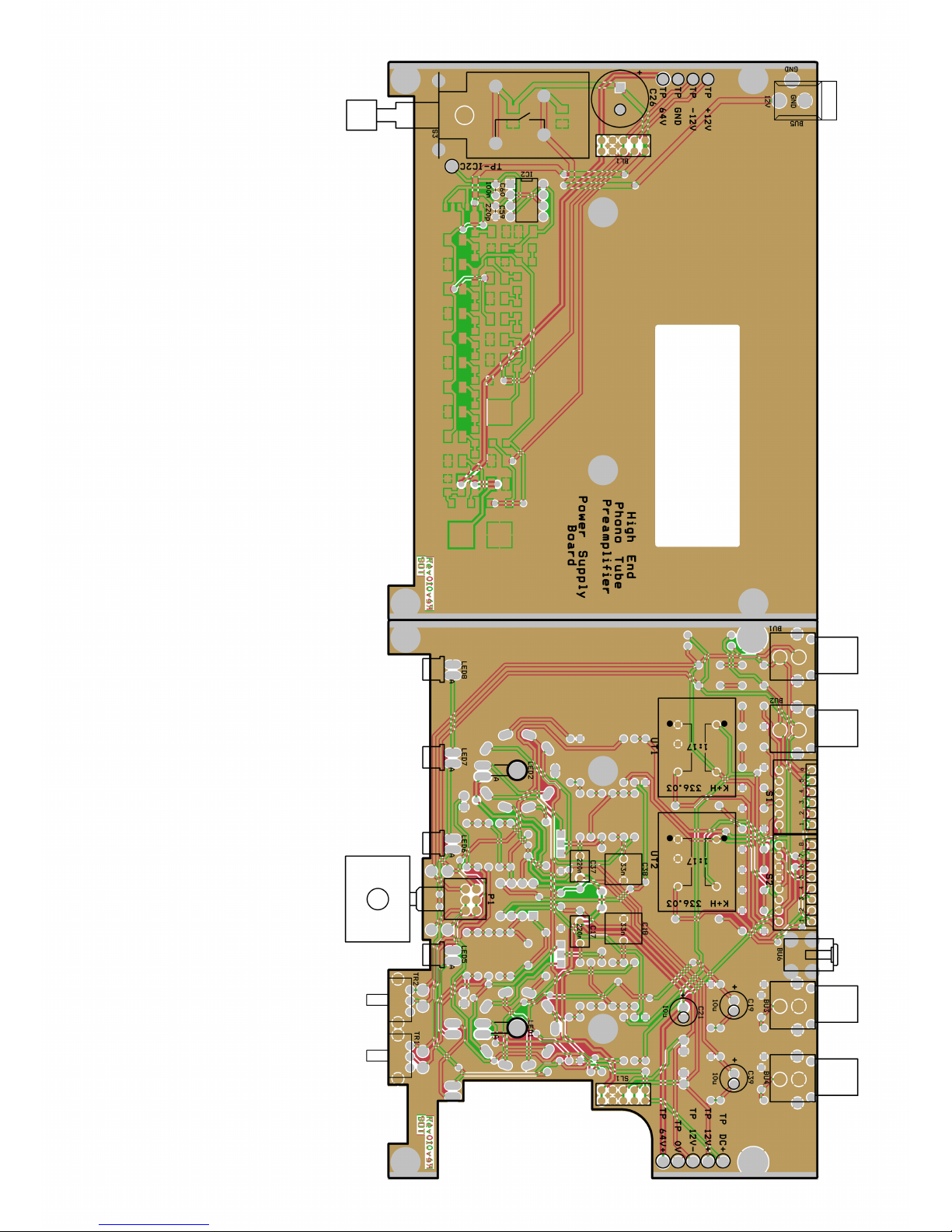
Flip the PCB so you can see the solder side. Solder first the four RCA sockets - and fix them
first on the shielding straps - next assemble the ground terminal and the two 6 and 8 pole DIP
switches S1 and S2, pay attention to a proper and even assembly .
Then fit the three 10 µF MUSE Electrolythic capacitors C19 / C39 / C21, whereby C21 must
be the 80 V type, followed by the two 33 nF WIMA capacitors C18 / C38 and the two 220 nF
capacitors C17 / C37.
The two small sliders TR1 and TR2 are assembled and next the potentiometer P1. It is very
important to ensure a clean right-angled seat. The spring tooth disc and the nut of the
potenziometers are not needed.
The wires of the two orange glowing 3 mm LEDs for the tube lighting are bent around 90 °
about 2 mm after exiting the body with tweezers the right way around (the long wire is the
anode), then fit these LEDs through the PCB holes in the middle of th tube socket and solder.
If you do not want to use the tube lighting, be sure to short the two solder pads for the LED with
a piece of wire.
The wires of the six 5 mm flat head UV LEDs are also angled, but only very
close to the component body; here a longer thumbnail can serve well. Please
note that two LEDs are fitted from the component side and four from the
solder side. It is recommended to solder the LEDs from the side from which
they were fitted on the PCB.
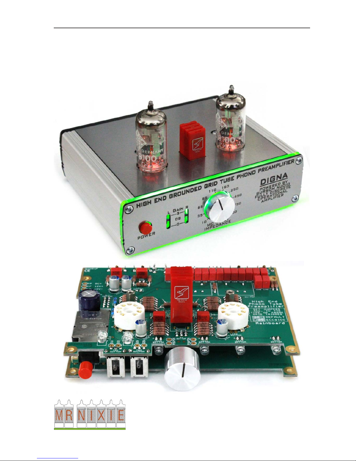
Now plug on the potentiometer knob: To do this, turn the wiper of the
potentiometer to a vertical position (12 or 6 o'clock). Fit the knob with the
marking pointing exactly after 12 o'clock (ie "upwards" in the direction of the
component side). Now fix the knob with its grub screw .
Finally , solder the two transformers UT1 / UT2 and the BURSON
operational amplifier. Note the orientation of the BURSON
amplifier (the kangaroo emblem must face to the front).
Now connect the motherboard board to the power supply board.
Make sure that the 10-pin. header for the power supply will
proper flush in the socket strip. Then fix the motherboard with
the two M3 x 10 spacers. Now fit the cover PCB, fix it with the
two remaining Torx M3 x 4 screws and slide this mounted
module into the U-profile as shown in the picture.
Only remove the protective film from this side
Pick up the green intermediate frame and only
remove now the protective film from the rear
side (see picture). Flip the intermediate frame
(you will now see the front side with protective foil) and fit the engraved front panel after
removing its protective foil onto it. Pay attention to the different position of the recesses; there
are offset to the "down side". Place the frames on the U-profile and secure with four Torx M3
x 10 screws.
Page 5
Assembly Manual DIGNA
Seite 5
Now unscrew the two T orx M3 x 4 screws from the top PCB again, pick up the top silver frame
and glue it on the top PCB after peeling off the protective foil. Y ou will notice that it gets a little
bit "tight" when placed in at the area around the BURSON operational amplifier. This is intended
and serves as an additional safeguard against accidental falling out. However , with the help
of a fingernail (around the BURSON), the cover can easily be pressed flush.
After re-screwing the two screws and plugging in the tubes, everything is now ready for enjoying
your vinyl music. Congratulations.
Anbieter • V endor
Jürgen Grau • Mr.Nixie • Ortsstraße 13 • D-07429 Rohrbach / Thüringen • Germany
[email protected] • http://www.Nixiekits.eu
Dieser DIY Phono Vorverstärker wurde in Deutschland entwickelt und zusammengestellt
This Phono preamplifier kit was carefully engineered and assembled in Germany
Page 6
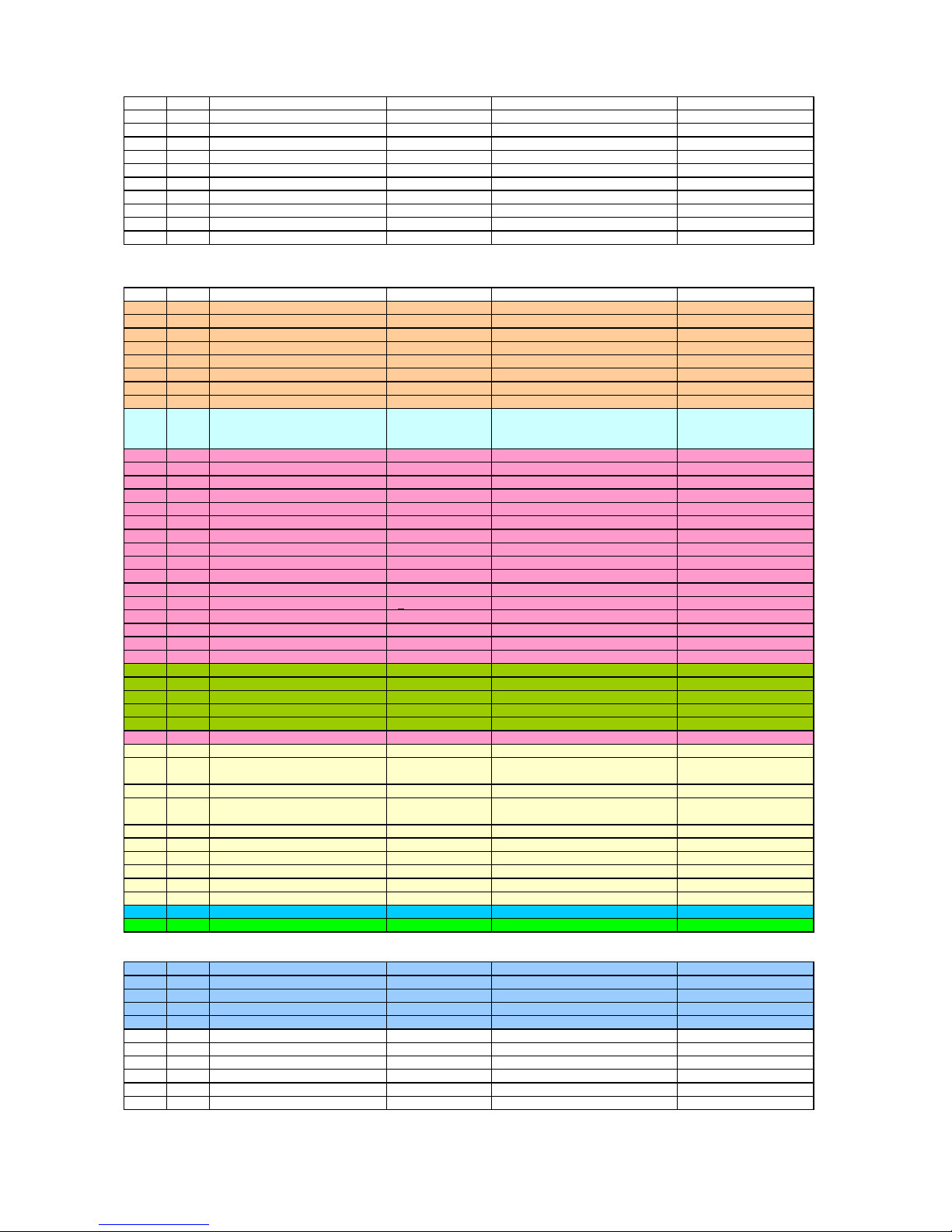
DIGNA Phono Tube Preamplifier Rev.10-17
Power Supply Board
SMT components preassembled and soldere
d
Pos. QtyTyp
e
V
alue/PackageRe
f
Remarks
1 17 SS14L / SS16L Schottky Diode Sub SMA D1…D17
2 21 2u2 100V ceramic 1210 C24,C25,C41….C58,C61
3 1 15V 500mW Zener Diode MiniMelf ZD1
4 1 BCX 51 / 52 / 53 SOT-89 T4
5 1 BCX 54 / 55 / 56 SOT-89 T3
6 1 LM317M D-PAK IC3
7 1 MC78M12 D-PAK IC4
8 1 MC79M12 D-PAK IC5
9 3 300R MiniMelf R55,R56,R57
10 2 15k MiniMelf R51,R54
Power Supply Board and Main Board
Through hole components
Pos. Qt
yType
V
alue/PackageRe
f
Remarks
11 1
DC
jack
FC681465P BU6 5.5/2.1 or 2.5 mm
12 1
Female Heade
r
2 x 5-pol. BL1
13 1
Male Heade
r
2 x 5 pol. SL1
14 4
Cinch
j
acks
shielded BU1…4
15 1
Dip-Switch 6-pol.
MDP-06 S1
16 1
Dip-Switch 8-pol.
MDP-08 S2
17 1
Ground Screw
13.42.322 BU6
18 2
Slider potentiomete
r
4k7 lin TR1,TR2 ALPS RD708
19 16
100pF FKP2 2,5%
100V RM 5,04
C10,C11A,C11B,C12,C13A,C13B,C
14A,C14B,C30,C31A,C31B,C32,C3
3A,C33B,C34A,C34B
WIMA
20 1
220pF ceramic "200"
50V RM 2.54 C59
21 1
100nF ceramic "104"
50V RM 2.54 C60
22 1
1µF ceramic "105"
rad. 5.08 mm C26
23 1
TS555CN
8-pol. DIP IC2
24 1
DIP-Socket
8-pol. DIP for IC2
25 4
4n7 FKP2 1%
50V RM 5.04 C16,C20,C36,C40 WIMA
26 1
4n7 FKP2 2,5
%
50V RM 5,04 C29 WIMA
27 2
33nF FKP2 2,5
%
50V RM 5,04 C18,C38 WIMA
28 2
220nF Pol
y
ester capacito
r
100V RM 5,04 C17,C37
29 4
220µF Pol
y
mer capacito
r
16V 6,3 x 8 mm C15,C22,C23,C35 KEMET
30 2
1µF ceramic capacito
r
50V RM 5,04 C27,C28
31 2
10µF MUSE electrol
y
thic cap. > 63V
C19,C39 NICHICON
32 1
10µF MUSE electrol
y
thic cap. 80V
C21 NICHICON
33 2
LED oran
g
e diffus
3 mm LED1,LED2
34 6
UV-LED 405 nm Flat hat 120°
5 mm LED3…LED8
35 1
P9A2R100FISX1102M
L
2 x 1k +log P1
VISHAY
36 1
Power Switch
ALPS SDDF S3
37 1
Knob for Power Switch
red for S3
38 2
Noval socket
18 mm for PCB TU1,TU2 gold plated
39 1
Potentiometer Knob
20 mm dia for P1 MENTOR 5226191
40 2
Audio-Transforme
r
K+H 336.03 UT1,UT2 Haufe GmbH & Co. KG
41 1
Burson Audio V6D Vivi
d
with DIP Socket IC1
42 6
10R 1%
CMF55 axial R12,R14,R29,R32,R34,R49 VISHAY / DALE
43 12
330R 1%
CMF55 axial
R15A,R15B,R16,R21,R22,R26,
R35A,R35B,R36,R41,R42,R46
VISHAY / DALE
44 2
2k0 1%
0207 axial R58,R59 YAEGO
45 8
10k 1%
CMF55 axial
R20,R23,R25A,R27,R40,R43,
R45A,R47
VISHAY / DALE
46 2
16k2 1%
CMF55 axial R18B,R38B VISHAY / DALE
47 2
31k6 1%
CMF55 axial R24A,R44A VISHAY / DALE
48 4
49k9 1%
CMF55 axial R11,R24B,R31,R44B VISHAY / DALE
49 2
82k5 1%
CMF55 axial R30,R50 VISHAY / DALE
50 6
267k 1%
CMF55 axial R19,R25B,R28,R39, R45B,R48 VISHAY / DALE
51 4
1M 1%
CMF55 axial R13,R18A,R33,R38A VISHAY / DALE
52 2 Dual Triode ECC8100 TU1,TU2
53 1 PCB Set 3 pcs.
Mechanics
54 2 Spacer A-I M3 x 13
55 2 Spacer I-I M3 x 10
56 4 Torx M3 x 4
57 8 Torx M3 x 10 self tapping
58 4 Bumper 8 x 2.8 mm black
59 1 Aluminium U frame GB 83 100 SA black
60 1 Top cover silvery 1.6 mm self adhesive
61 1 Front cover engraved silvery 1.6 mm self adhesive
62 1 Rear cover engraved silvery 1.6 mm self adhesive
63 1 Front mounting frame 3 mm LISA green
64 1 Rear mounting frame 3 mm black matt
Page 7
Page 8
 Loading...