

Page 1
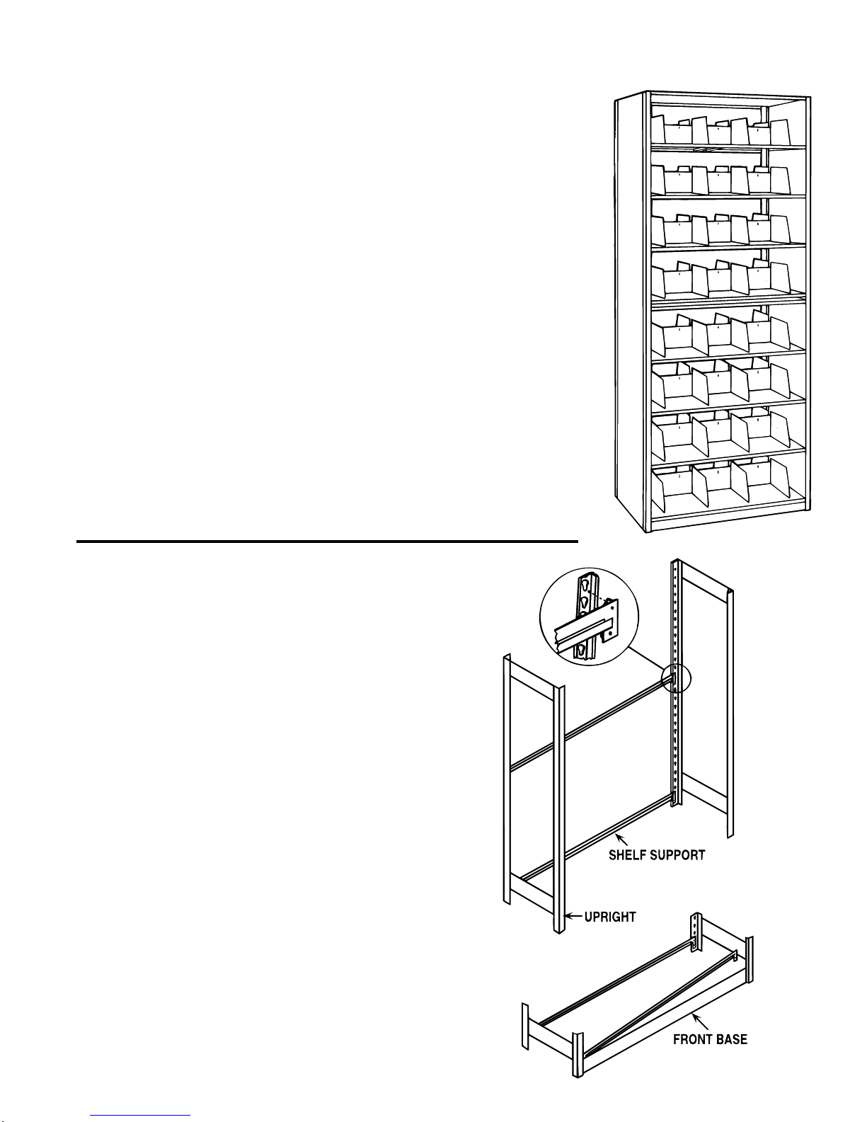
Record Master® Installation Instructions
General Instructions
1. Check parts and bundles against packing slip to be sure all parts and bundles
were received.
2. Sort parts so that like parts are together. This will make installation easier and
faster.
3. Read through the entire instruction sheet carefully before attempting to
assemble Record Master units.
4. Determine that the floor will support shelving load. It is the end users' responsibility to provide adequate flooring.
5. Check your floor plan for layout and assemble from left to right. Measure and
mark floor for intended layout; pre-plan exact location of all units with regard to
columns, lights, windows and obstructions.
6. All uprights must be level and plumb. Shim under bottom of posts. If not level
and plumb, it will be difficult to assemble adder units and component parts.
7. Units may be secured to walls with wall anchors and to each other using "U" or
clothespin clips. Ranges may be anchored across open aisle to opposite units
or to a wall with aisle ties.
8. If assembled units are to be moved about on a dolly or by hand truck, the
bottom shelf and supports must be locked in place by inserting four (4) safety
plugs in post keyhole above shelf surface.
Installation Steps
1. Uprights & Shelf Supports
a. Assemble units from bottom up.
b. Hold uprights in place and temporarily insert shelf
support near mid-point on back posts to space uprights.
c. Locate bottom shelf support with rivet tabs down at back
of unit.
••• For 2-1/2" front base, insert rivet shoulder in 1st and
2nd keyhole slots.
••• For 4-1/4" front base, insert rivet shoulder in 2nd
and 3rd keyhole slots.
2. Front Base
a. Place front base inside upright front posts and insert front
bottom shelf support with rivet tabs down, positioned as
noted in Step 1c.
b. Shelf support retains front base in place.
STEP 1
- 1 -
STEP 2
Page 2
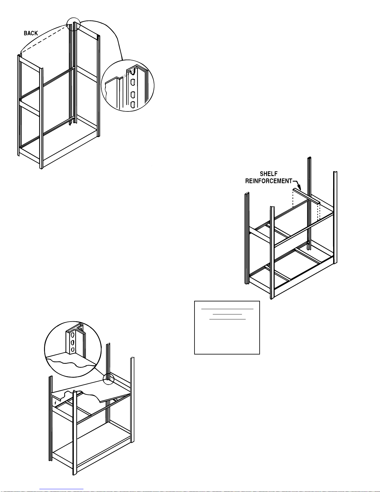
3. Backs
a. Backs, if required, should be installed at this time b. The corner notches in back must be at bottom.
c. Insert offset flange edge of back between post and
d. Optional back holders may be added as stiffeners on top
NOTE: Units 97-1/4" high or higher use two-piece backs.
STEP 3
4. Shelf Spacing
a. Locate shelf supports from bottom of unit spaced to suit
requirements. Upright posts are punched 1-1/2" on center.
b. Set shelf supports at each end by tapping in place with a
rubber mallet to seat rivets tightly into keyhole slots.
before additional shelf supports are inserted.
supports then buckle the back out to spring the opposite
edge flange in between the post and supports.
or bottom edge of back.
The top section is 34-1/16" high and has a
spotwelded splice guide on the lower edge to receive
the upper edge of the bottom section.
5. Shelf Reinforcements
a. The need for shelf reinforcements is determined by the
size of shelves and planned shelf and load distribution
(see catalog for general guidelines).
b. Shelf reinforcements drop in place across two shelf
supports, as shown.
STEP 6
Quantity of Shelf Reinforcements
STEPS 4 & 5
Recommended for
Filing & X-Ray Shelves
36"w x 18 & 24" d -use 1
36"w x 30"d -use 2
42"w x 18" & 24"d -use 2
42"w x 30"d -use 3
48"w x 18" & 24"d -use 2
48"w x 30"d -use 3
6. Shelves
a. Shelves should now be placed on supports and
reinforcements as shown at left.
b. On single entry Record Master slotted shelves, front
slots are 2-1/16" from front edge of unit, rear slots are
29/32" from back.
All other shelves are symmetrical and may be placed
either way in unit.
- 2 -
Page 3
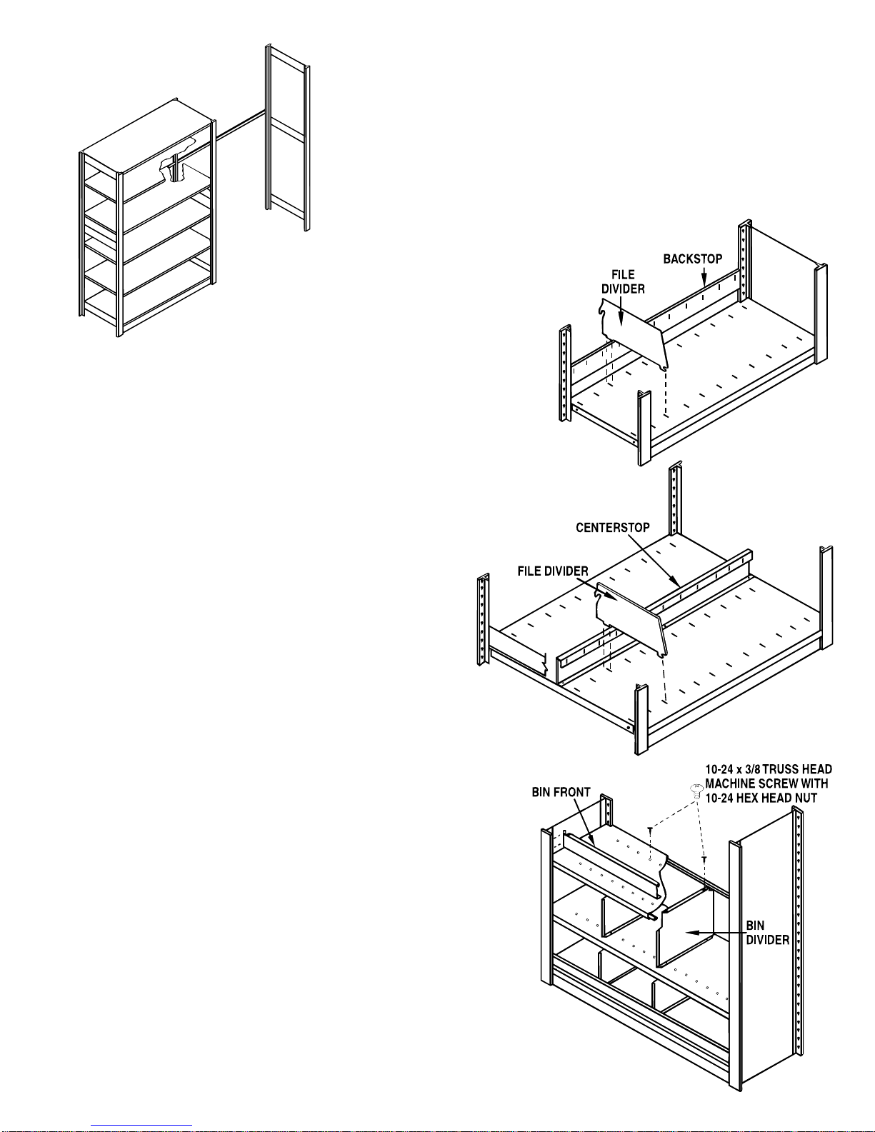
7. Adder Units
(requires T uprights)
a. Insert temporary support at mid-point between finished unit and adder
upright as done in Step 1.
b. Repeat Steps 2 through 6 for each unit to complete the range of
shelving.
STEP 7
8a. Backstops & File Dividers (single entry units)
a. Slotted backstops for file dividers are installed on rear posts of
single entry units.
b. Insert lanced tab in 3rd keyhole above shelf. Backstop must be
positioned with slots closest to top edge.
c. Adjustable file dividers may now be inserted by hooking bottom
front hook of divider into front shelf shot and dropping back
divider tab into shelf slot and rear divider hook into backstop slot.
STEP 8A
8b. Centerstops & File Dividers (double entry units)
a. Slotted centerstop for file dividers is bolted along
center line of double entry shelf. Use three (3)
3/16" x 3/8" bolts with keps nuts.
b. Adjustable file dividers may now be inserted by
hooking bottom front hook of divider into front shelf
slot and dropping back divider tab into shelf slot and
rear divider hook into centerstop slots.
8c. X-Ray Units (bin fronts and bin dividers)
a. Bin fronts must be installed before bin dividers.
b. Rivets in bin front are inserted into 1st and 2nd keyhole of
upright above top of shelf. When seated, the bin front rests
flush on top of shelf.
c. Higher bin fronts may be made by locating additional bin fronts
one on top of the other.
d. Bin dividers are installed with the square rectangular notch
positioned at top front corner under shelf to clear support.
Flanges with holes at top and bottom of divider are to the right
as you face the divider.
e. Fasten divider to shelf through holes in flanges in space above
or below with 10-24 x 3/8 THMS and 10-24 hex head nut.
These fasteners may be reused to relocate bin dividers if
adjustment of spacing is required.
- 3 -
STEP 8B
STEP 8C
Page 4
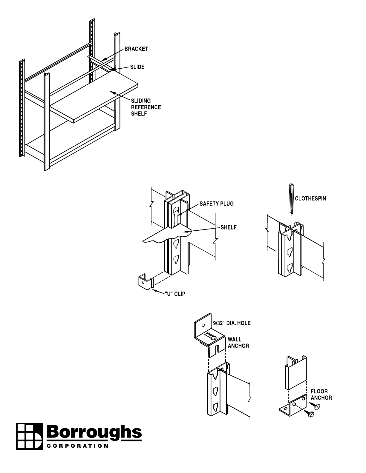
STEP 9
9. Sliding Reference Shelf (optional)
a. Sliding reference shelves should be located at a
convenient working height or positioned to suit
conditions of assembly for shelf filing.
b. The slides and brackets are pre-assembled and
attached to the shelf.
c. Double entry unit brackets are bolted to supports, as
above, with a separate sliding reference shelf on
each side of unit. Brackets have backstops, with
rubber bumpers at center, to stop shelf travel.
d. Shelf supports, from which reference shelf hangs,
must have four (4) safety plugs inserted in keyholes
above the shelf covering the supports to prevent shelf
and supports from lifting when the sliding reference
shelf is fully extended. (See Step 10A.)
10. Small Parts
a. Safety plugs prevent shelf and shelf
support from lifting.
b. "U" clips secure back-to-back units
at bottom of angle or T uprights.
c. Clothespin clips are used at top of
angle or T uprights to join units
together.
STEPS 10 A & B
11. Wall & Floor Anchors
a. Optional wall anchors are used for anchoring sections
to walls and are inserted into top of angle or T upright
at posts against the wall. Fastener used into wall
should suit type of building construction material used.
b. Optional floor anchors are used for securing section to
floor and are attached to upright post with screws (field
drilled) or welded. Anchor plate has two (2) holes for
lag screws or expansion anchors to suit type of floor.
STEP 10 C
3002 N. BURDICK STREET KALAMAZOO, MI 49004-3483
800-748-0227 FAX: 269-342-4161 www.borroughs.com
- 4 -
STEP 11A
STEP 11B
Form #53-50423-00A • April 2004
 Loading...