

Page 1

BK-75
I
NSTRUCTION
MANUAL
BURR KING MFG. CO., INC
1220 Tamara Lane
Warsaw, MO 65355
www.burrking.com
(660)438-8998 • 800-621-2748
Fax (660)438-8991
BK-75
DUST COLLECTOR
Grinder not included
Page 2

BURR KING MFG. CO., INC.
1220 TAMARA LANE
WARSAW MO 65355
WWW.BURRKING.COM
(660) 438-8998 (800) 621-2748
FAX (660) 438-8991
Safe operation and good practice use of your BK-75 dust collection
system April 2001
The BK-75 dust collection system is designed to accept one dust inlet. Dust is drawn into the BK-75 by
its onboard air suction system. The air stream and dust is passed through a filter bank where a significant
amount of the dust is removed from the air stream. The air is then ducted out of the BK-75. The following
minimum safe practices should be read, understood, and practiced by all users of the BK-75, and those
persons who maintain the BK-75, or are present in the BK-
To minimize fire, explosion, health and other risks to personnel and property:
Do not use your BK-75 to collect materials prone to explosion unless it has been specifically
modified to be “explosion proof”.
Do not draw debris from different alloys into the BK-75 system.
Do not use water or other electrically conductive fluid in your BK-75 unless it has been
specifically modified for wet operation.
Do not mix wood, plastic, paper, or other flammable material debris with metal or other
high temperature dust/debris.
Do use a spark-arresting device if your BK-75 will be used to collect debris from materials
that spark or otherwise create ignition level debris when worked.
Do consult with the appropriate authorities to be certain that your BK-75 installation and
its intended use comply with local, state, and federal codes.
Do use approved inhalation protective devices in conjunction with the BK-75.
Do use approved protective eye, face, hand, and body protection when grinding, polishing,
or otherwise creating dust and debris that you intend the BK-75 collect.
Do disconnect all power to the BK-75 (and any equipment connected to it) prior to
performing adjustments, maintenance, or other activity that involves opening any cover on
the BK-75.
Do read, understand, and abide by the operating and maintenance instructions provided for
the BK-75.
Do use specified replacement parts and filters.
Do maintain the BK-75 in specification compliant condition.
Do call Burr King Manufacturing at 1-800-621-2748 if you need assistance.
75 work area.
Page 3

Caution!
Application of Dust Control Equipment
• Combustible materials such as buffing lint, paper, wood, aluminum or steel dust, weld
fume, or flammable solvents represent fire or explosion hazards. Use special care when
selecting and operating all dust or fume collection equipment when combustible
materials are present to protect workers and property from damage due to fire and/or
explosion. Consult and comply with National and Local Codes relating to fire or
explosion and all other appropriate codes when determining the location and operation
of dust or fume collection equipment.
• When combustible materials are present, consult with an installer of fire extinguishing
systems familiar with these types of fire hazards and local fire codes for
recommendations and installation of fire extinguishing and explosion protection
systems. Donaldson dust collection equipment is not equipped with fire extinguishing
or explosion protection systems.
• DO NOT allow sparks, cigarettes or other burning objects to enter the hood or duct of
any dust or fume control equipment as these may initiate a fire or explosion.
• For optimum collector performance, use only Donaldson replacement parts.
Warning – Improper operation of a dust control system may contribute to conditions in the
work area or facility that could result in severe personal injury and product or property
damage. Check that all collection equipment is properly selected and sized for the intended use.
Page 4

Contents
Description ........................................................... 4
Purpose and Intended Use .................................... 4
Operation ............................................................. 5
Inspection on Arrival ........................................... 6
Installation Codes and Procedures ....................... 6
Installation ........................................................... 6
Site Selection, Grade-Mounted Units ............ 6
Unit Location ................................................. 6
Electrical Wiring .................................................. 7
Rigging Instructions ............................................. 7
Hoisting Information ..................................... 7
Typical Installation .............................................. 8
Standard Equipment ............................................ 9
This manual contains specific
precautionary statements relative
to worker safety. Read thoroughly
and comply as directed. Discuss the
use and application of this equipment
with a Donaldson representative.
Instruct all personnel on safe use and
maintenance procedures.
Optional Equipment ............................................. 9
Hopper ........................................................... 9
Hopper Attachments.................................... 11
Indoor Exhaust Deflector ............................. 12
Outdoor Exhaust Deflector .......................... 13
Ductwork ..................................................... 14
Suction Tube Assembly ................................ 14
®
Magnehelic
Gauge ..................................... 16
Outrigger Pack ............................................. 18
HEPA Filter .................................................. 19
Exhaust Silencer ........................................... 21
Attenuator .................................................... 22
Chamber Silencer ......................................... 23
Automatic Shaker ........................................ 23
Preliminary Start-Up Check ............................... 26
Start-Up ............................................................ 26
Service Information ........................................... 27
EZ Filter Pack™ Installation ......................... 27
Dust Disposal ............................................... 29
Troubleshooting ................................................. 30
Service Notes ..................................................... 33
Warranty............................................................ 36
Magnehelic® is a registered trademark of Dwyer Instruments, Inc.
Data Sheet
Model Number _______________________________ Serial Number ________________________________
Ship Date ____________________________________ Installation Date ______________________________
Customer Name ____________________________________________________________________________
Address ____________________________________________________________________________
____________________________________________________________________________
Filter Type ____________________________________________________________________________
Accessories ____________________________________________________________________________
Other ____________________________________________________________________________
Page 5

Description
Purpose and Intended Use
Cabinet Series 50 to 80 dust collectors are selfcontained, intermittent-duty collectors with
envelope-style filters. Using the EZ Filter Pack™
filter system, Cabinet series collectors provide
highly efficient, low maintenance air cleaning.
Filters are cleaned using the standard manual filter
shaker or an optional motorized filter shaker which
cleans the filters automatically each time the unit is
turned off. The EZ Filter Pack is designed for quick,
easy filter replacement without the use of special
tools.
Designed to increase the versatility of the unit,
standard options include a hopper package for a
5-gallon pail or 55-gallon drum, indoor and
outdoor exhaust deflectors, HEPA filter packs, and
exhaust silencers. Four filter media choices and
three construction options are among the many
options available to customize the unit to the
specific application.
Caution!
• Misuse or modification of this
equipment may result in personal injury.
• Do not misuse or modify.
Cabinet collectors provide excellent efficiency on
nuisance dust generated in industrial operations
and are a good choice for low airflow, light-load
applications that do not require continuous airflow.
Typical applications include grinding, buffing and
polishing, abrasive blasting, batch mixing, and bag
dumping. Often, individual Cabinet collectors are
dedicated to one or two machines.
Four filter media selections offer a wide variety of
characteristics: cotton sateen is the standard media
and provides good efficiency in applications up to
180° F; polyester sateen provides the same
efficiency, but has higher temperature resistance
(240° F) and is more abrasion-resistant; woven
polyester provides better dust release capabilities
with lower efficiency; and polypropylene provides
some chemical resistance up to 180° F.
Standard galvanized construction includes
galvanized metal support bars, slide latches, bag
clips, and hardware to support most applications.
Optional stainless-steel construction is tailored to
corrosive environments. This option includes
stainless steel clips and screws if the screws
protrude into the dirty-air chamber. Slide latches,
support bars, and other hardware located in the
clean-air chamber remain galvanized steel.
Grounded, non-spark construction includes the
standard frame and polyester sateen filter media,
an additional stainless steel wire-mesh insert,
stainless-steel bag clips, and ground wires.
Page 6
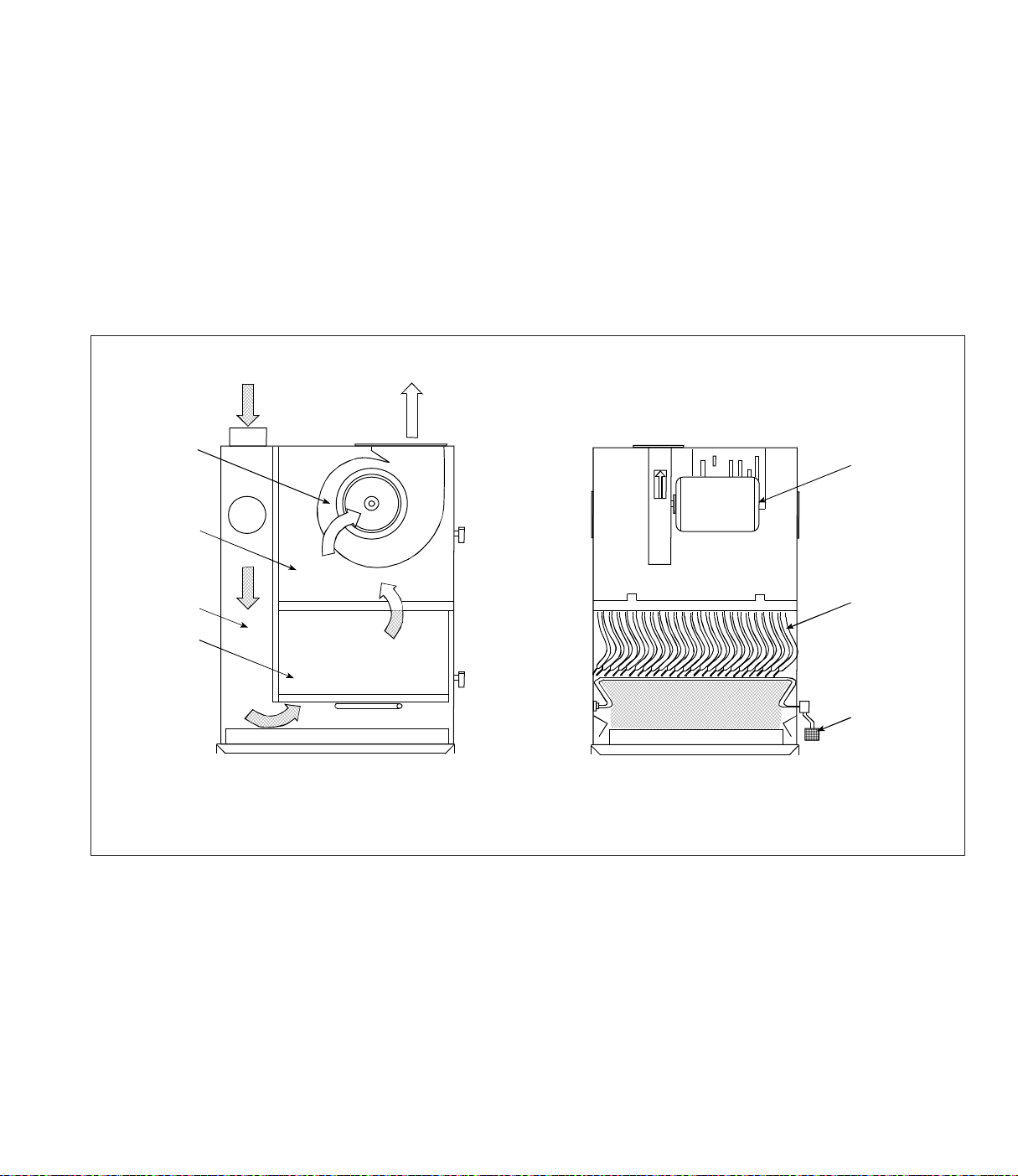
Operation
During normal operation, dust-laden air enters the
unit through the dirty-air inlet and passes through
the unit where the dust collects on the outside
surface of the filter media. As dust collects on the
filter surfaces, a dust cake forms, which actually
improves the efficiency of the filters. The greater
the amount of dust cake accumulated, the higher
the efficiency of the filter.
The filtered air flows up through the center of the
filters and into the clean-air chamber. Clean,
dirty-air inlet
blower ON
clean-air
chamber
clean-air outlet
filtered air discharges through clean-air outlet
located on top of the unit.
Pushing down on the hand- or foot-operated shaker
pedal and releasing rapidly six times completes
manual filter cleaning. The releasing action causes
the dust cake to fracture and fall into the dust
storage area. Motorized filter shakers are optional
and automatically clean the filters each time the
unit is turned off.
blower
motor OFF
fan rotation
stopped
inlet zone
filter bags
Normal Operation
Side sieï
Unit Operation
Filter CleaninÖ
Front sieï
filter bags
shaker pedal
press down
and release
quickly six
times
Page 7

Inspection on Arrival
Installation
1. Inspect unit on delivery.
2. Report any damage to the delivery carrier.
3. Request a written inspection report from the
Claims Inspector to substantiate claim.
4. File claims with the delivery carrier.
5. Compare unit received with description of
product ordered.
6. Report incomplete shipments to the delivery
carrier and your Donaldson representative.
7. Remove crates and shipping straps. Remove
loose components and accessory packages
before lifting unit from truck.
Installation Codes and Procedures
Caution!
OSHA may have requirements regarding
recirculating filtered air in your facility.
Consult with the appropriate local
authorities to ensure compliance with all
codes regarding recirculating filtered air.
1. Safe and efficient operation of the unit depends
on proper installation.
2. Authorities with jurisdiction should be
consulted before installing to verify local codes
and installation procedures. In the absence of
such codes, install unit according to the
National Electric Code, NFPA No. 70-latest
edition.
Site Selection, Grade-Mounted Units
1. The unit can be located on a reinforced
concrete foundation or rooftop.
2. Wind, seismic zone, and other live-load
conditions must be considered when selecting
the location for rooftop-mounted units.
3. Provide clearance from heat sources and
interference with utilities when selecting the
location for suspended units.
4. Portable units require no special installation
accommodations.
Unit Location
1. When hazardous conditions or materials are
present, consult with local authorities for the
proper location of the collector.
2. Foundation or roof support must be capable of
supporting the entire weight of the unit, plus the
weight of the collected material, piping, and
ductwork.
3. Prepare the foundation in the selected location.
Install anchor bolts to extend a minimum of
1 3/4-inches above foundation.
4. Locate the collector to ensure the shortest and
straightest inlet- and outlet-duct length, easy
access to electrical and compressed-air
connections, and routine maintenance.
3. A qualified installation and service agent must
complete installation and service of this
equipment.
Page 8
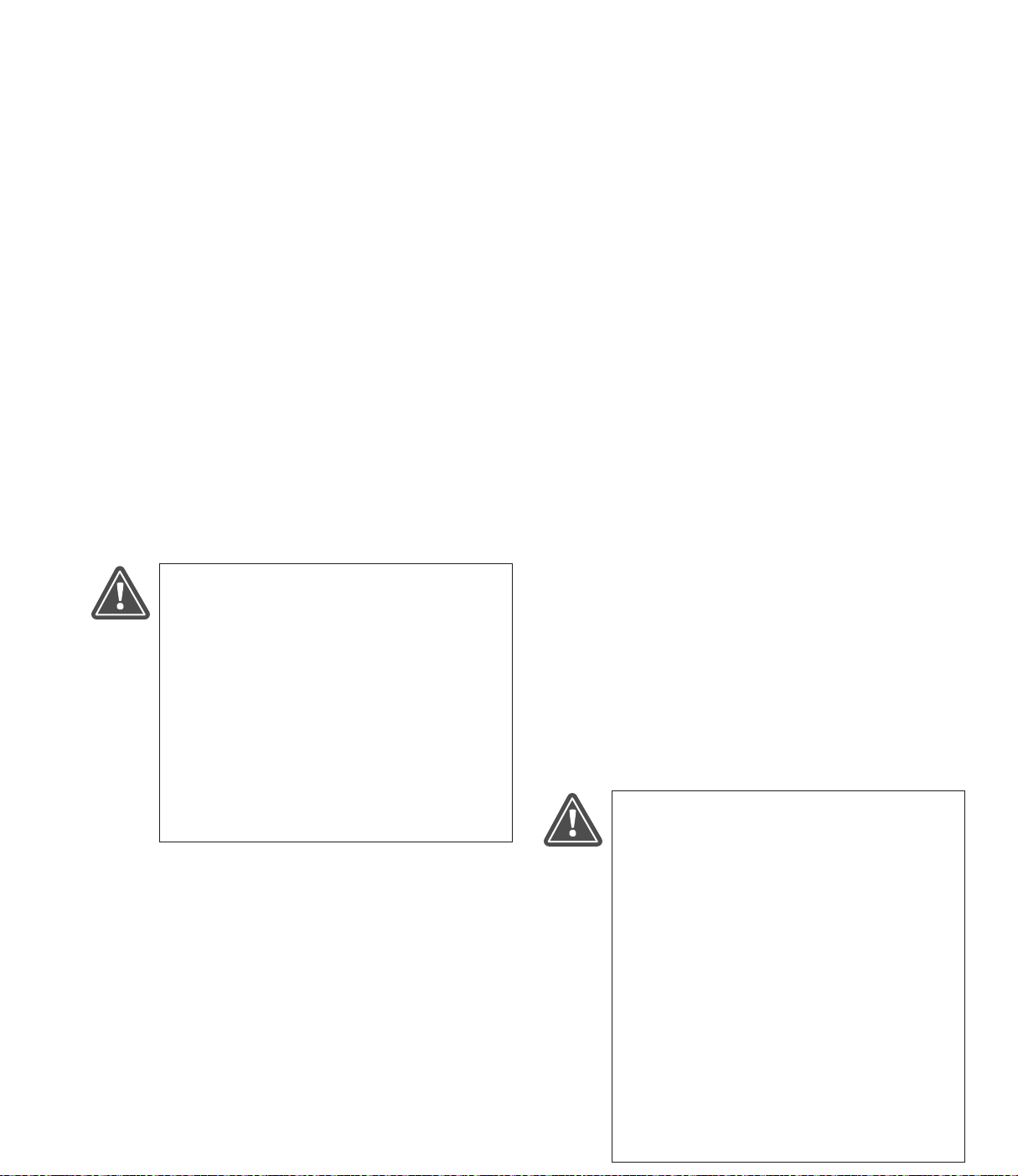
Electrical Wiring
Rigging Instructions
1. All electrical wiring and connections, including
electrical grounding, should be made in
accordance with the National Electric Code,
NFPA No. 70-latest edition.
2. Check local ordinances for additional
requirements that apply.
3. The appropriate wiring schematic and electrical
rating must be used. See unit’s rating plate for
required voltage.
4. If the unit is not furnished with a factory-
mounted disconnect, an electric disconnect
switch having adequate amp capacity shall be
installed in accordance with Part J, Article 430
of the National Electrical Code, NFPA No. 70latest edition. Check unit’s rating plate for
voltage and amperage ratings.
5. Refer to the wiring diagram for the number of
wires required for main power wiring and
remote wiring.
Caution!
• Electrical installation must be
performed by a qualified electrician
and comply with all applicable
national and local codes.
• Turn power OFF during installation
or maintenance.
• Do not install in classified hazardous
atmospheres without an enclosure
rated for the application.
SuÖÖested Tools & Equipment
Clevis Pins and Clamps Lifting Slings
Crane or Forklift Pipe Sealant
Drift Pins Pipe Wrenches
Drill and Drill Bits Screwdrivers
End Wrenches Socket Wrenches
Large Crescent Wrench Spreader Bars
Hoisting Information
1. Use all lifting points provided.
2. Use clevis connectors, not hooks, on lifting
slings.
3. Use spreader bars to prevent damage to unit’s
casing.
4. Check the Specification Control drawing for
weight and dimensions of the unit,
subassemblies, and components to ensure
adequate crane capacity.
5. Allow only qualified crane operators to lift the
equipment.
6. Refer to applicable OSHA regulations and local
codes when using cranes, forklifts, and other
lifting equipment.
7. Lift unit and accessories separately, and
assemble after unit is in place.
8. Use drift pins to align holes in section flanges
during assembly.
Caution!
• Failure to lift the collector correctly
can result in severe personal injury or
property damage.
• Use appropriate lifting equipment and
adopt all safety precautions needed
for moving and handling the
equipment.
• A crane or forklift is recommended
for unloading, assembly, and
installation of the collector.
• Location must be clear of all
obstructions, such as utility lines or
roof overhang.
Page 9
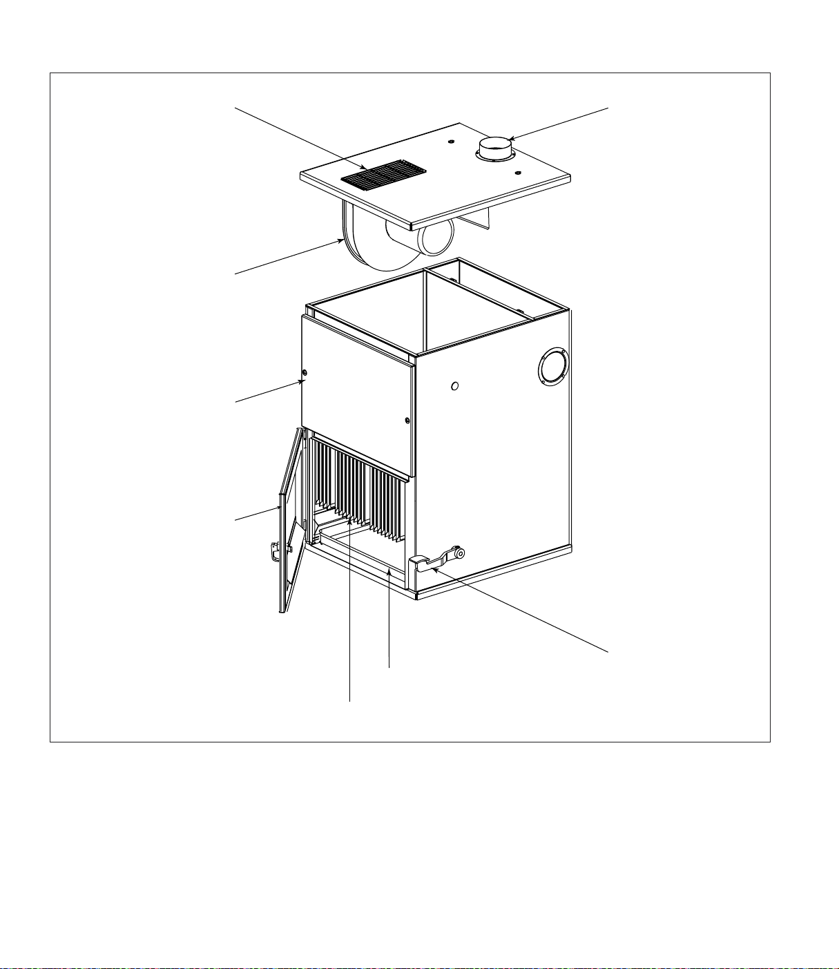
Typical Installation
clean-air outlet
blower
top door assembly
dirty-air inlet
one of three
optional locations
bottom door assembly
shaker pedal
dust drawer
EZ Filter Pack
Typical Installation
Page 10
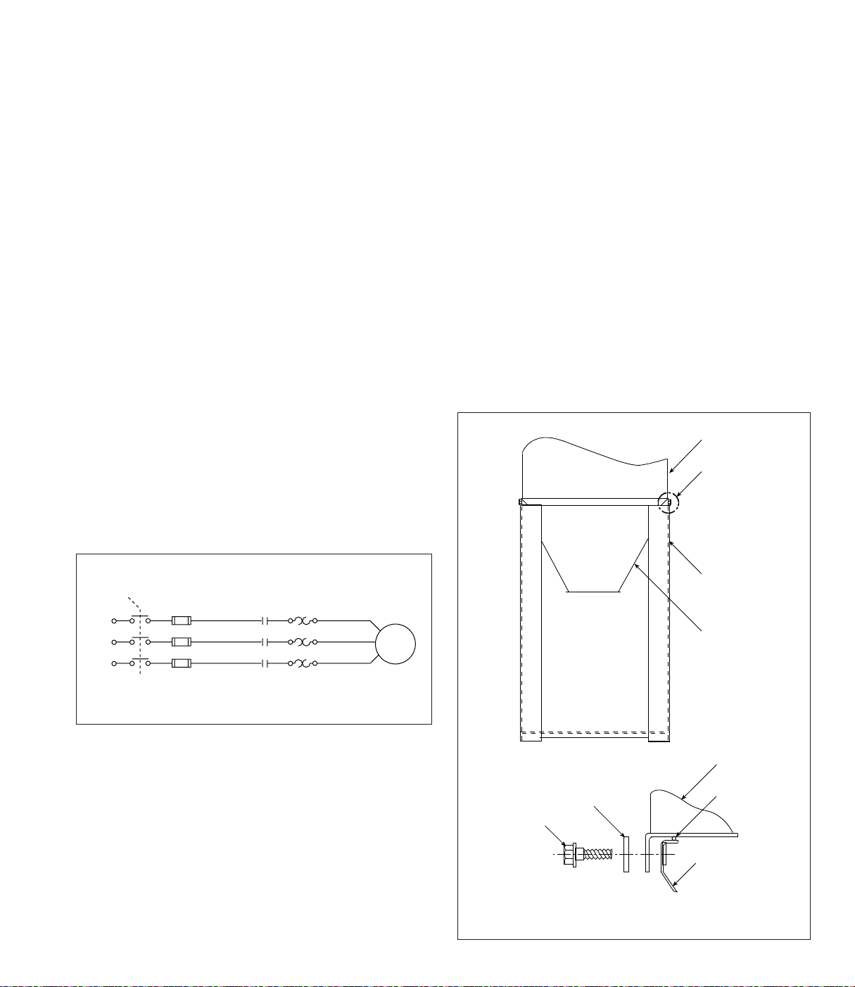
Standard Equipment
Optional Equipment
Standard equipment consists of a self-contained
unit housing the filters, blower, clean- and dirty-air
chambers, and dust drawers. Locate the unit as
close to the dust source as possible, except where
explosive or flammable material is present.
1. Make the electrical connections to the
customer-supplied safety disconnect switch,
blower, and blower starter.
2. Turn power ON at source.
3. Turn the blower motor ON then OFF to check
for proper rotation by referencing the rotation
arrow located on the blower housing. A blower
running in the wrong direction will still deliver
approximately 40% of its rated air volume
making proper rotation extremely important.
To reverse rotation, sinÖle-phase poïer supply:
Follow manufacturer’s instructions on the
motor’s nameplate.
To reverse rotation, three-phase poïer supply:
Turn electrical power OFF at source and switch
any two leads on the output-side of the fanmotor starter.
Hopper
1. Attach legs and cross bracing to hopper using
3/8-16 x 1-in bolts, washers, and nuts as
shown. Cross braces can be installed to allow
front or back hopper access.
Note: The 5-gallon pail hopper does not
require cross bracing.
2. Position the hopper and leg assembly on the
foundation’s anchor bolts and fasten securely.
3. Apply 1/4-in diameter rope-type sealant to the
hopper’s top flange.
4. Lift cabinet over hopper and leg assembly and
lower slowly.
5. Secure with bolts, washers, and nuts supplied.
cabinet
see Detail A
Disconnect
1L1
1L2
1L3
208/230/460/575/60/3
1FU
2FU
3FU
Motor Starter Wiring Diagram
L1
L2
L3
1M
1OL
1T1
1T2
1T3
fan
motor
3/8-in flat washer
3/8-16 x 1-in bolt
Detail A
Hopper to 5-Gallon Pail Assembly
leg
hopper
cabinet
sealant
hopper
Page 11
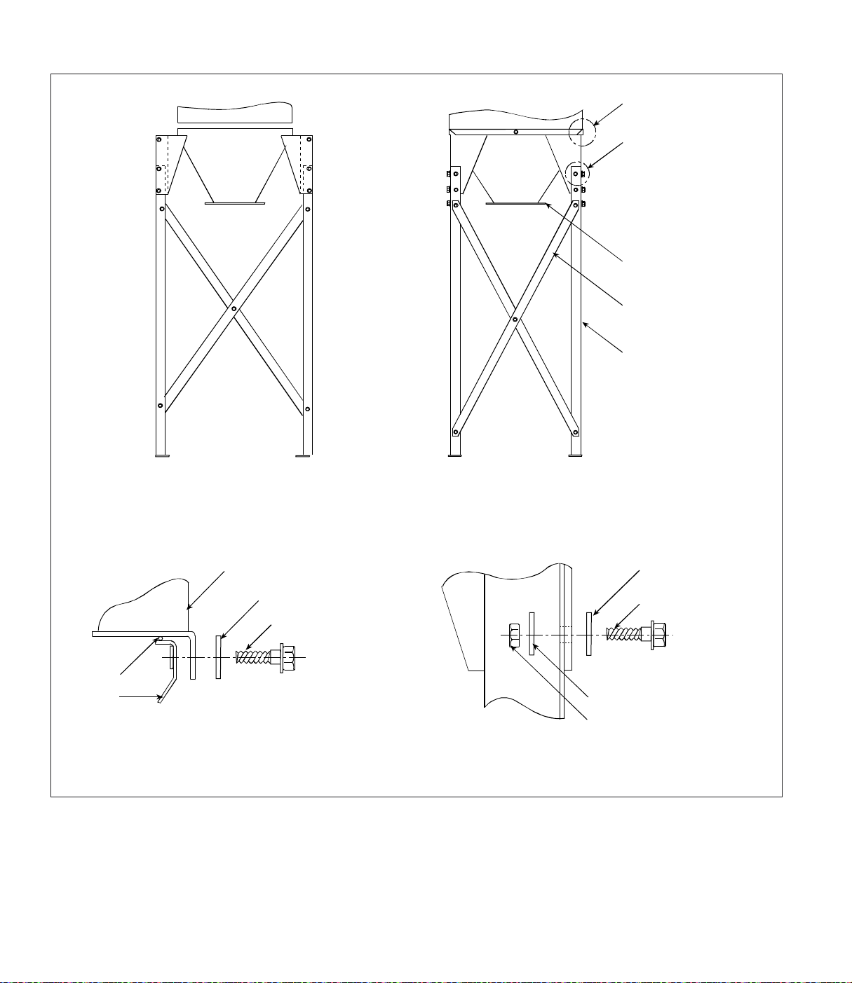
Front sieï Side sieï
See Detail A
See detail B
hopper
cross brace
two 2 x 50.62-in
leg
sealant
hopper
Detail A
cabinet
3/8-in flat washer
3/8-16 x 1-in bolt
Hopper to 55-Gallon Drum Assembly
3/8-in flat washer
3/8-16 x 1-in bolt
3/8-in flat washer
3/8-16 hex nut
Detail _
Page 12
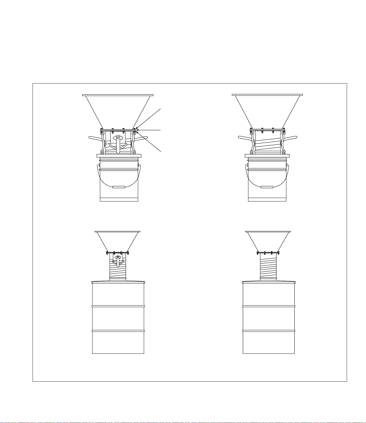
Hopper Attachments
5- or 55-Gallon Drum Packs with or without Slide Gate
1. Apply 1/4-in diameter rope-type sealant to the
drum cover mounting plate flange.
hopper flange
sealant
drum or pail cover
mounting plate
Pail Pack
with Gate Valve
2. Fasten the drum cover assembly to the hopper
flange using the hardware supplied.
Pail Pack
without Gate Valve
Drum Cover Pack
with Gate Valve
Drum Cover Pack
without Gate Valve
5- or 55-Gallon Drum Packs with and without Slide Gate
Page 13
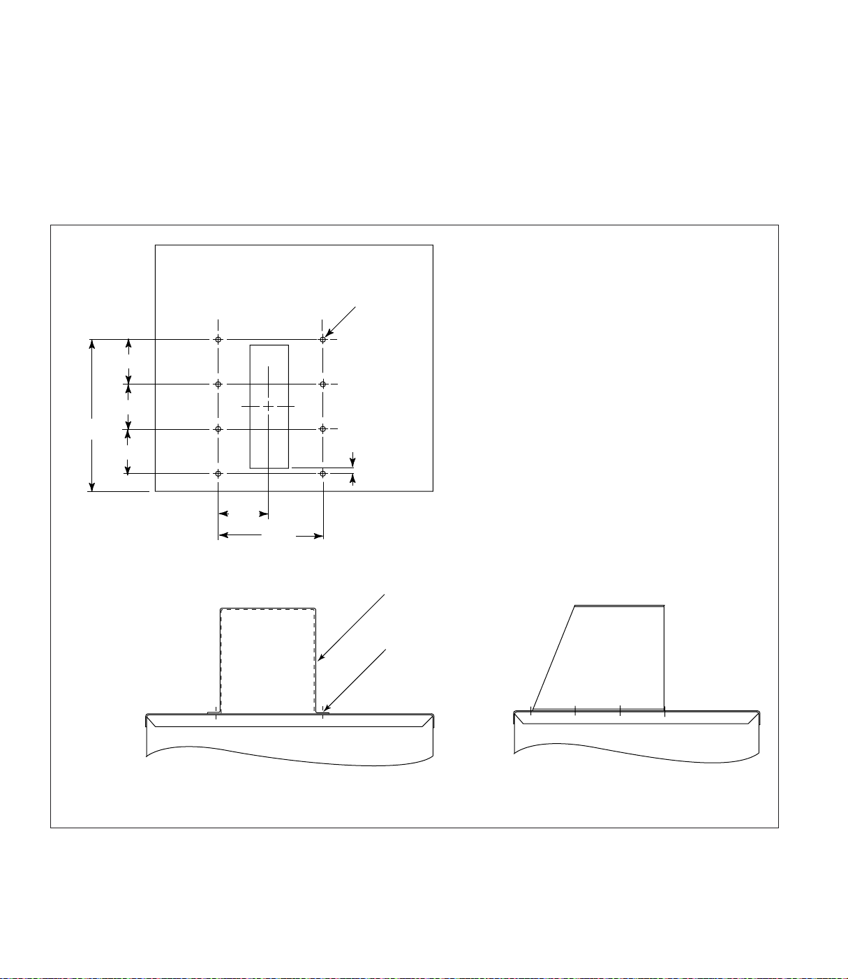
Indoor Exhaust Deflector
1. Remove the top door assembly and set aside.
2. Place a piece of non-combustible cloth over the
filters in the clean-air chamber to protect them
from drilling chips.
3. Use a .213-in diameter drill bit to drill eight
holes as shown.
.213
8x
3.50
3.50
10.50
3.50
.50
4. Position the indoor exhaust deflector on the
cabinet top and fasten using eight 1/4-20
thread-cutting screws. Tighten securely.
5. Carefully remove the cloth protecting the
filters. Replace the top door assembly and
tighten securely by hand.
4.20
8.41
Drill Location
Front View
indoor
exhaust deflector
1/4-20 thread
cutting screw
Left Side View
Indoor Exhaust Deflector
Page 14
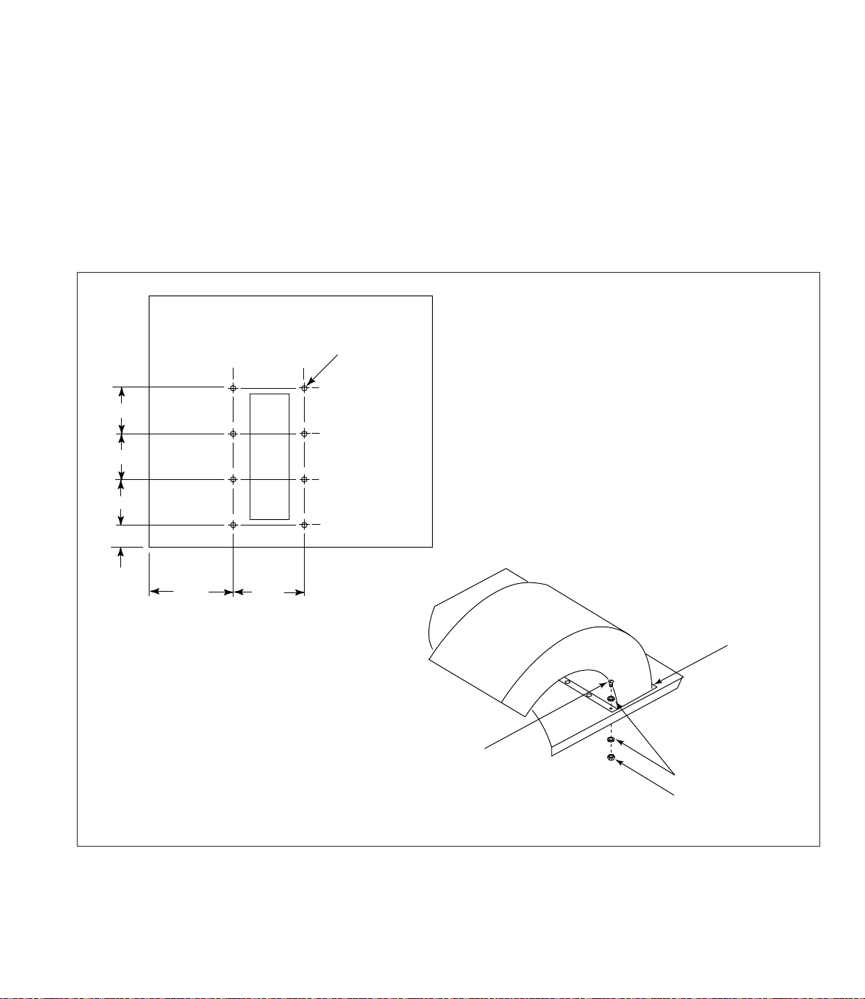
Outdoor Exhaust Deflector
3.25
3.25
3.25
7.31
.218
8x
2.37
8.94
sealant
10-24 x 1/2-in
slot-head screw
#10 flat washer
10-24 hex nut
1. Remove the top door assembly and set aside.
2. Place a piece of non-combustible cloth over the
filters in the clean-air chamber to protect them
from drilling chips.
3. Use a .218-in diameter drill bit to drill eight
holes as shown.
4. Position the indoor exhaust deflector on the
cabinet top, align holes and fasten using eight
#10-24 x 1/2-in bolts, washers, and nuts
supplied. Tighten securely.
5. Apply sealant around outside edge of the
exhaust deflector.
6. Carefully remove the cloth protecting the
filters. Replace the top door assembly and
tighten securely by hand.
Outdoor Exhaust Deflector
Page 15
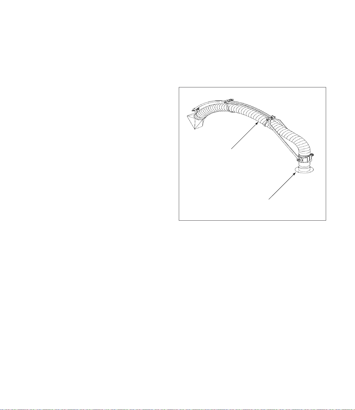
Ductwork
Suction Tube Assembly
Note: If unit is operated with more than the
maximum permissible inlet size, the fan
motor can overload or dust can settle in the
duct due to low air velocity.
1. Inlet collars can be located on the side, top, or
back of the cabinet by removing the desired
inlet cover plate and installing the inlet collar
using the same screws.
2. Use the shortest possible inlet duct. Avoid the
use of tees or flexible, wire-molded duct except
where machine motion or vibration needs to be
isolated. Flexible duct has a high static pressure
and reduces airflow.
3. Size duct for the recommended air velocity of
the conveyed material or material may collect
inside the duct.
4. Connect joints with sheet metal screws, rivets,
or sealer. Finish each joint with sealer or duct
tape.
Note: Sheet metal screws may cause fibrous or
stringing particulate to accumulate inside
duct. Use rivets or sealant in these
conditions.
3- and 4-Inch
1. Apply a thin layer of grease to the inside
surface of the inlet collar.
2. Slide the suction tube base into the inside of the
inlet collar. Swivel the suction tube to lubricate
all surfaces.
3 or 4-in
suction tube
assembly
inlet collar assembly
3 or 4-in
3- and 4-Inch Suction Tube Assembly
Page 16
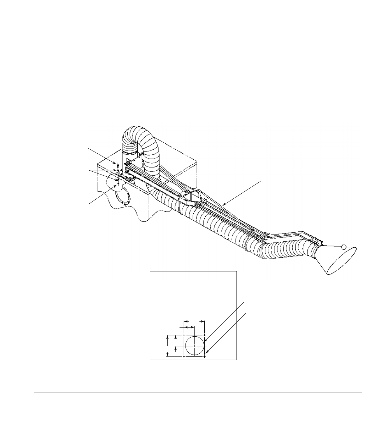
6-Inch
1. Remove the inlet access covers on the top and
back of the unit and set aside.
2. Use a .343-in diameter drill bit to drill four
holes in the top of the unit as shown.
3. Apply sealant around the inside edge of the bolt
pattern.
5/16-18 x 1.25-in
hex bolt
5/16-in
flat washer
5/16-18
hex nut
silicone sealant
4. Position the suction tube assembly on the
collector top, align holes, and fasten securely
using 5/16-18 x 1 1/4-in bolts, washers, and
nuts supplied.
5. Replace the back access cover plate.
6-in x 10-ft
suction tube assembly
rear inlet access cover
3.38
6.75
3.38
6.75
Roof Drill Pattern
6-Inch Suction Tube Assembly
existing inlet hole
.34-in diameter
4 places
Page 17
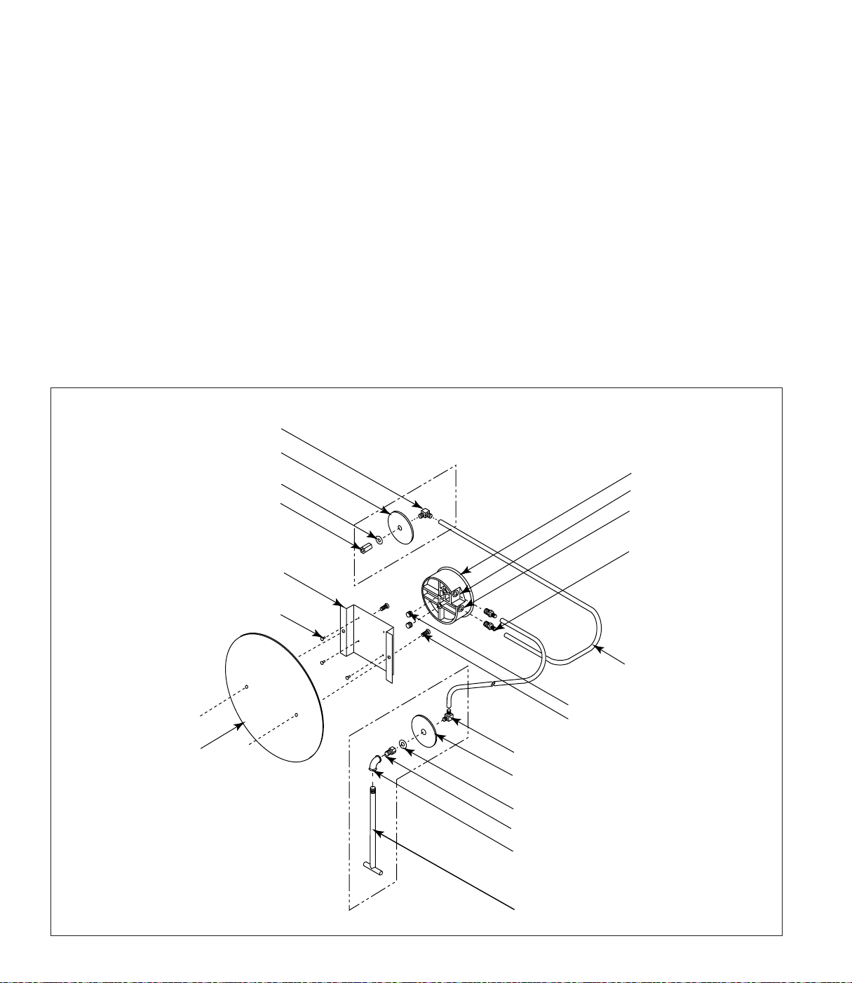
Magnehelic Gauge
The Magnehelic is a differential pressure gauge
used to measure the pressure difference between
the clean- and dirty-air chambers and provides a
visual display of filter change requirements. The
high-pressure tap is located in the dirty-air
chamber and the low-pressure tap is located in the
clean-air chamber.
1. Choose a convenient, accessible location on or
near the unit for mounting that provides the
best visual advantage.
If unit is equipped with factory-installed pressure
taps, skip to Step 5.
2. Before drilling, place a piece of non-combustible
cloth over the filter opening in the clean-air
chamber to protect them from drilling chips.
1/8-in NPT x 90°
male elbow
clean-air chamber
drill location, see detail A
3/8-in flat washer
1/8-in NPT coupling
3. Place a piece of wood behind the drill location
in the dirty-air chamber to protect the filters
from damage by the drill bit. Use a .406-inch
diameter bit to drill the holes as shown in
Magnehelic Gauge, Detail A.
4. Mount the pressure tap hardware on the cleanair chamber panel. Mount the pressure tap with
the tee inside the dirty-air chamber.
5. Plug the pressure ports on the back of the gauge
using two, 1/8-in NPT pipe plugs supplied.
Install two, 1/8-in NPT male adapters supplied
with the gauge into the high- and low-pressure
ports on the side of the gauge. Attach the
mounting bracket using three, #6-32 x 1/4-in
screws supplied.
Magnehelic gauge
high-pressure port
low-pressure port
mounting bracket
#6-32 x 1/4-in mounting screws
support structure
mounting surface
two, 1/8-in NPT
adapters
plastic tubing
two, 1/8-in NPT pipe plugs
two, self-drilling screws
1/8-in NPT x 90° male elbow
dirty-air chamber
drill location, see detail A
3/8-in flat washer
1/8-in NPT adapter
1/8-in NPT x 90° elbow
static pressure tee
Magnehelic Gauge Assembly
Page 18
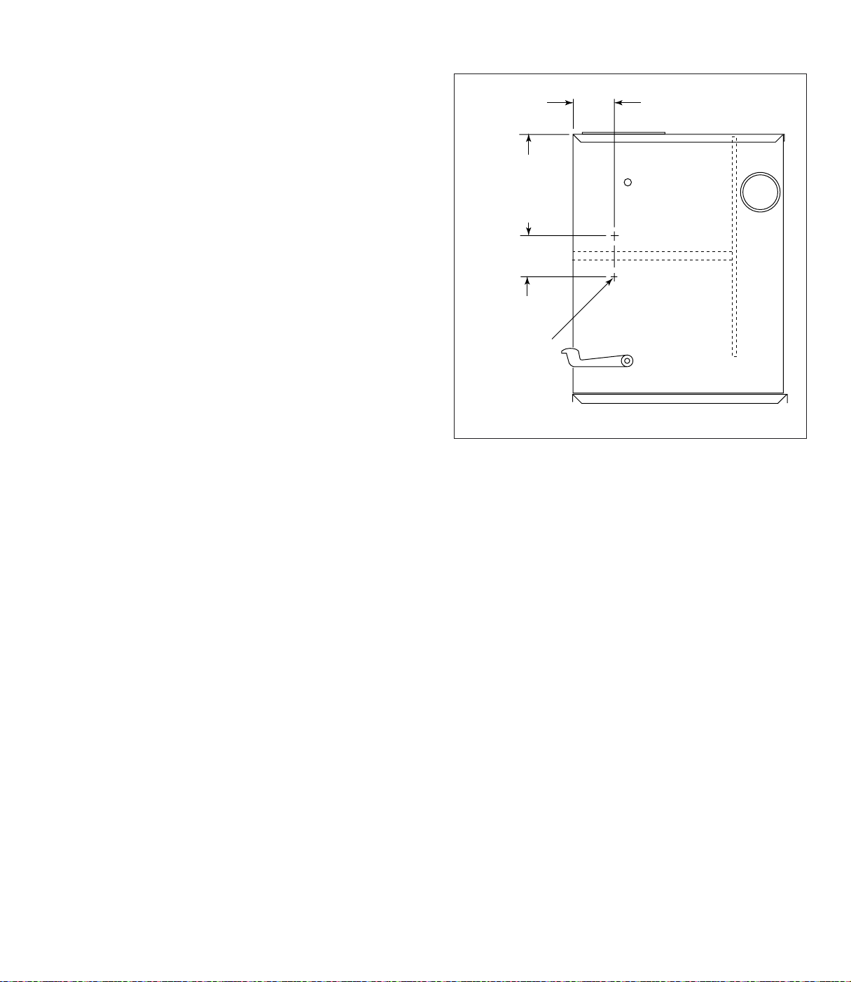
6. Mount the gauge and bracket assembly to the
50 10.14
60 13.14
70 12.02
80 14.08
4.75
4.00
.406 diameter
2 places
Series
supporting structure using two self-drilling
screws.
7. Thirty-five feet of plastic tubing is supplied and
must be cut in two sections. Connect one
section of tubing from the gauge’s high-pressure
port to the pressure fitting located in the dirtyair chamber. Connect remaining tubing from
the gauge’s low-pressure port to the fitting in
the clean-air chamber. Additional tubing can be
ordered from your representative.
8. Carefully remove the cloth protecting the
filters. Close access doors and tighten securely
by hand.
9. Zero and maintain the gauge as directed in the
manufacturer’s Operating and Maintenance
Instructions provided.
Magnehelic Gauge Detail A
Page 19
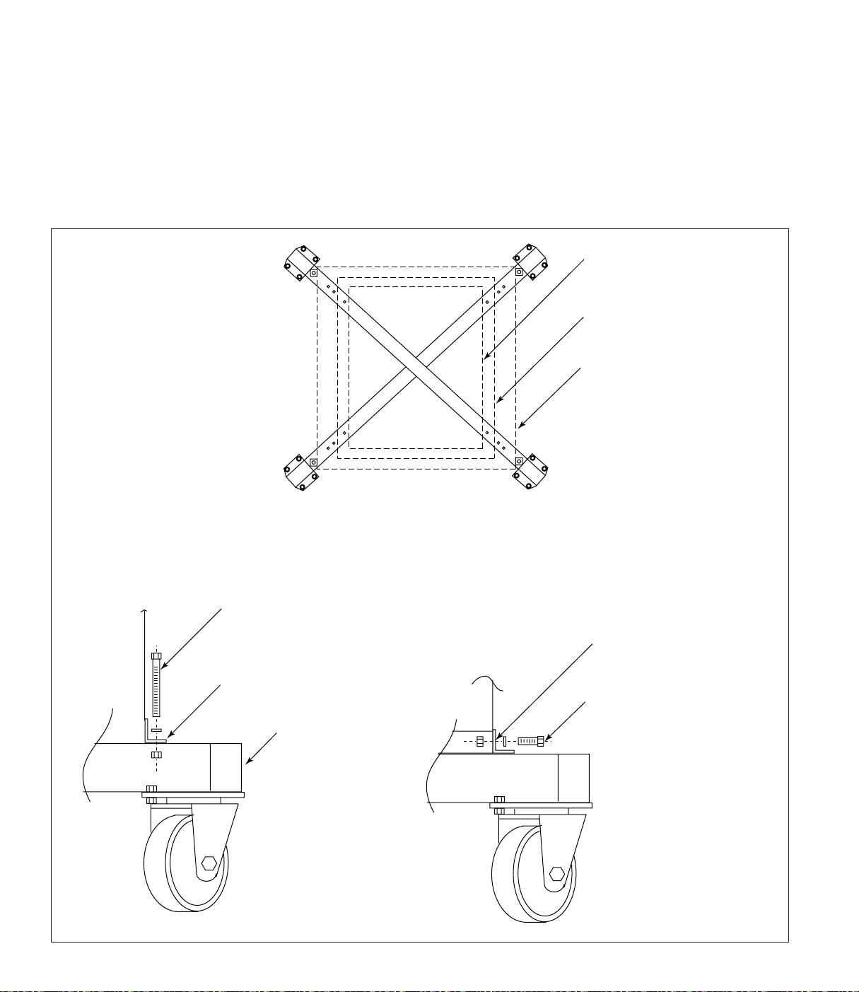
Outrigger Pack
Note: Outrigger pack is for use with dust drawer
models only.
1. Center the unit on the outrigger pack aligning
the appropriate bolt patterns.
2. Fasten the four mounting tabs to the outrigger
base using four 5/16-18 x 4-in bolts, washers,
and nuts. Tighten securely.
3. Drill four .312-in diameter holes in the cabinet
base using the mounting tab holes as a guide.
4. Attach the cabinet base to the mounting tabs
using four 5/16-18 x 3/4-in bolts, washers, and
nuts. Tighten securely.
Series 50
Series 60 and 70
Series 80
Center the unit on the outrigger pack
aligning the appropriate bolt patterns.
fasten mounting tabs
to outrigger base using
5/16-18 x 4-in bolts,
flat washers, and hex nuts
mounting tab
outrigger base
match drill .312-in
diameter holes in
cabinet base
fasten cabinet base
to mounting tabs using
5/16-18 x 3/4-in bolts,
flat washers, and hex nuts
Outrigger Pack Assembly
Page 20
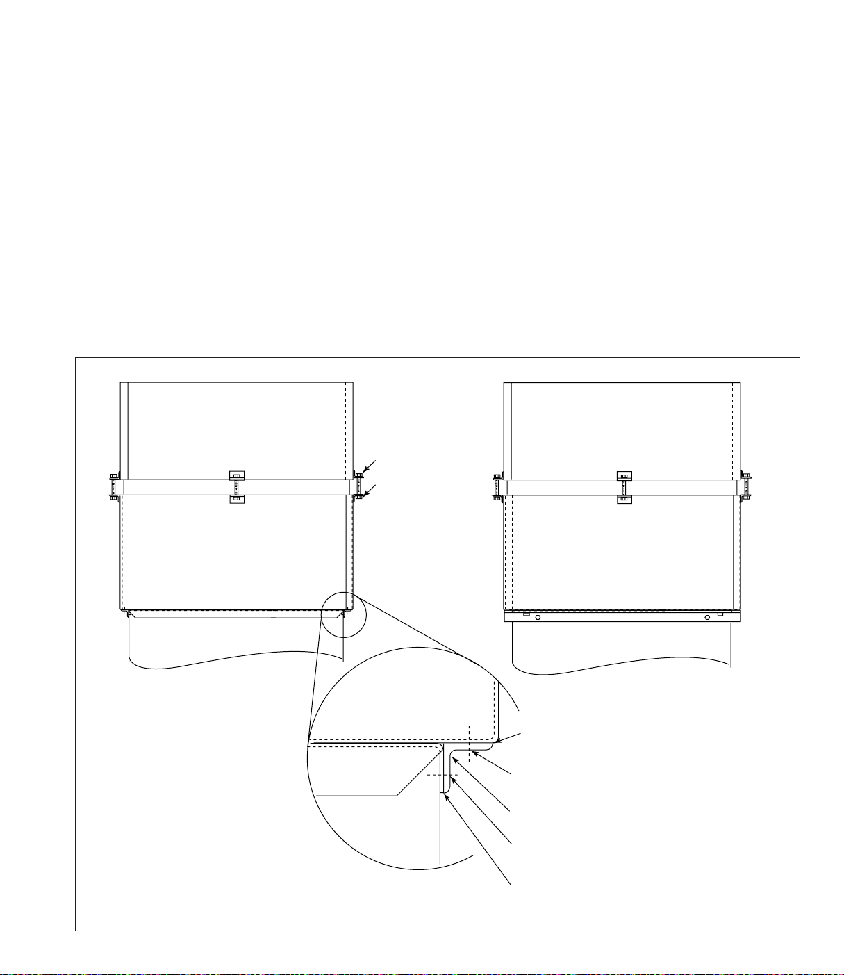
HEPA Filter
Models 60 and 70
1. Position the HEPA filter pack on top of the unit
as shown.
2. Remove the top door assembly and set aside.
3. Place a piece of non-combustible cloth over the
filters in the clean-air chamber to protect them
from drilling chips.
4. Position angle bracket on each side of the unit
flush with the top and under the HEPA filter
brackets as shown.
5. Using the holes in the angle brackets as a guide,
drill two .213-in diameter holes in the cabinet
side and two in the HEPA filter pack.
5/16-18 lock nut
5/16-18 x 2.5-in
hex bolt
6. Remove HEPA filter pack and apply silicone
sealant around mounting surface.
7. Fasten angle bracket to cabinet using four
1/4-20 thread-cutting screws supplied.
8. Align holes in the HEPA filter pack angle
brackets with the holes drilled in the bracket
top surfaces and secure using four 1/4-20
thread-cutting screws.
9. Carefully remove the cloth protecting the
filters. Replace the top door assembly and
tighten securely by hand.
Front View
HEPA Filter Pack
Cabinet Top
HEPA Filter Models 60 and 70
drill four .213-in diameter
holes per side
1 2 3 4
Side View
silicone sealant around
all mounting surfaces
match-drill two .213-in diameter holes
through HEPA filter pack
1 x 1 x 1/8-in angle bracket
match-drill two .213-in diameter holes
through cabinet top and wall
silicone sealant around
all mounting surfaces
Page 21
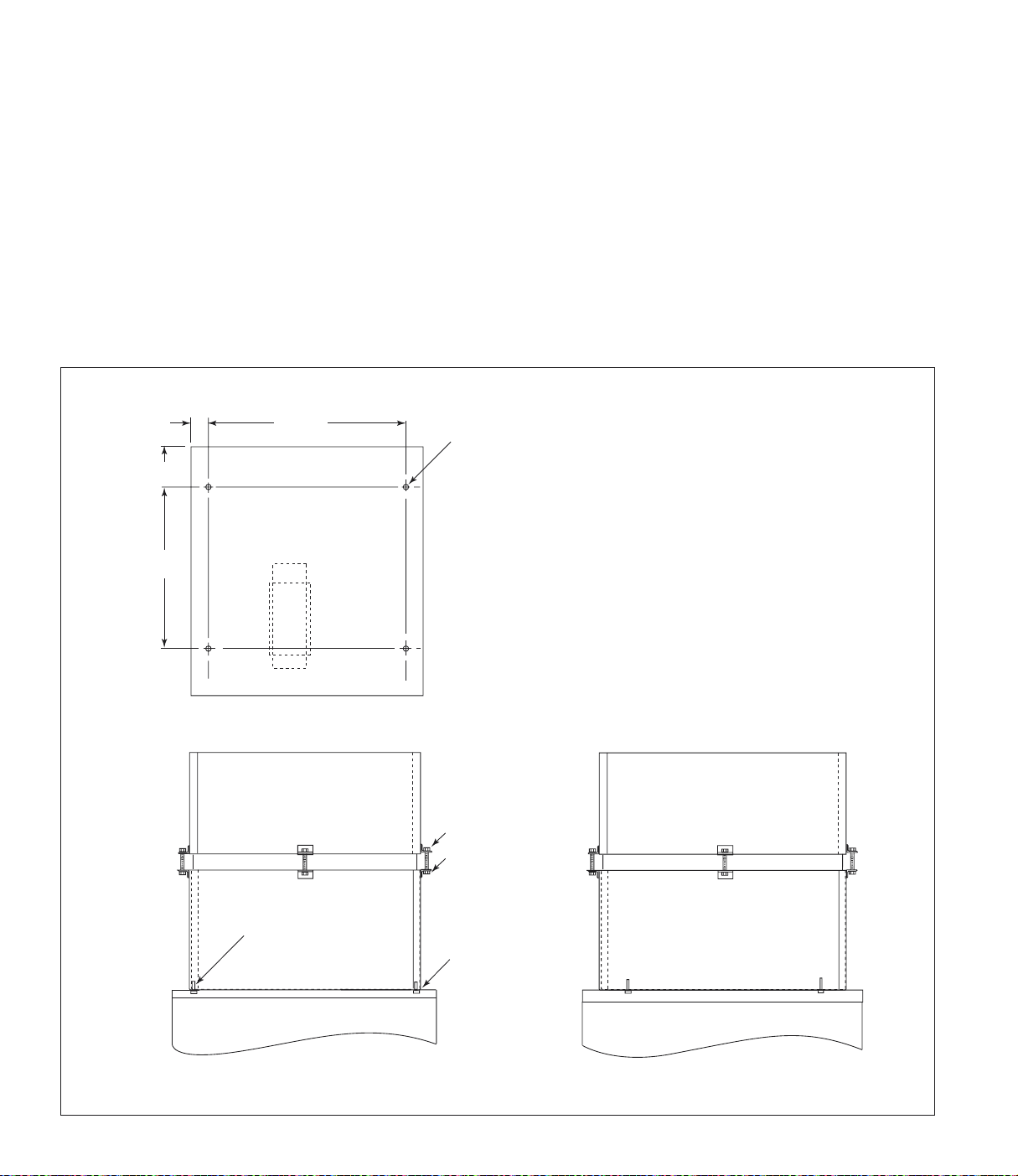
Model 80
1. Remove the top door assembly and set aside.
2. Place a piece of non-combustible cloth over the
filters in the clean-air chamber to protect them
from drilling chips.
3. Use a .312-in diameter drill bit to drill four
holes in the collector top as shown.
4. Apply sealant around sealing surface on
cabinet top.
5. Position the HEPA filter pack on top of the unit
aligning holes.
6. From inside the clean-air chamber, fasten the
filter pack to the top using four 1/4-20 threadcutting screws.
7. Carefully remove the cloth protecting the
filters. Replace the top door assembly and
tighten securely by hand.
4.23
20.00
2.38
23.68
.312
4x
Top View Drill Location
5/16-18 lock nut
5/16-18 x 2.5-in
hex bolt
four 1/4-20
thread-cutting screws
Front View Right Side View
silicone sealant
around all
mounting
surfaces
HEPA Filter Model 80
Page 22
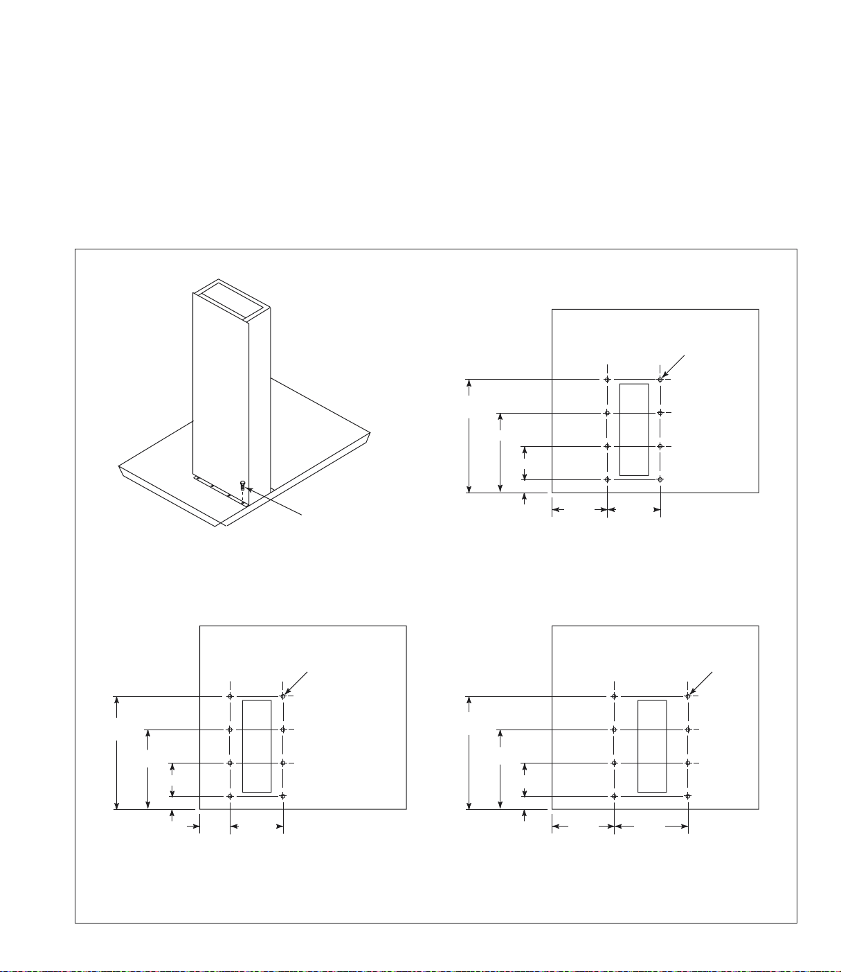
Exhaust Silencer
If an exhaust silencer was ordered with the unit,
the mounting holes are pre-drilled.
To install an add-on silencer:
1. Remove the top door assembly and set aside.
2. Place a piece of non-combustible cloth over the
filters in the clean-air chamber to protect them
from drilling chips.
3. Use a .116-in diameter drill bit to drill eight
holes in the collector top as shown.
4. Position the exhaust silencer, align holes, and
fasten securely with #7 x 1/2-in screws
supplied.
5. Carefully remove the cloth protecting the
filters. Replace the top door assembly and
tighten securely by hand.
.116
8x
10.21
7.75
2.56
1.65
11.17
8.11
3.06
1.92
#7 x 1/2-in
self tapping screw
8 required
.116
8x
11.45
8.95
3.50
1.95
3.90 6.81
Series 60 and 70 Drill Location Series 80 Drill Location
5.24 5.06
Series 50 Drill Location
8.01 8.41
.116
8x
Exhaust Silencer Installation
Page 23
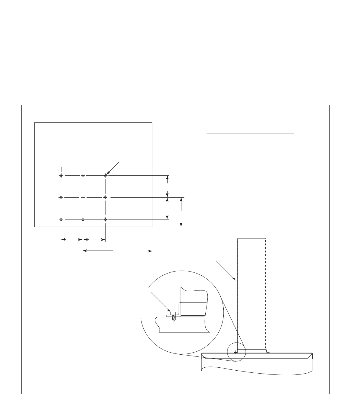
Attenuator
If an attenuator was ordered with the unit, the
mounting holes are pre-drilled.
To install an add-on attenuator:
1. Remove the top door assembly and set aside.
2. Place a piece of non-combustible cloth over the
filters in the clean-air chamber to protect them
from drilling chips.
.213
8x
3. Use a .213-in diameter drill bit to drill eight
holes in the collector top as shown.
4. Position the attenuator assembly, align holes,
and fasten securely using eight 1/4-20 threadcutting screws supplied.
5. Carefully remove the cloth protecting the
filters. Replace the top door assembly and
tighten securely by hand.
Model A B
Series 50 14.50 8.50
Series 60 and 70 14.50 8.63
Series 80 18.00 8.63
6.81
6.81
6.81
Drill Location
6.81
B
A
attenuator
1/4-20 thread
cutting screw
8 required
Front View
Attenuator Installation
Page 24
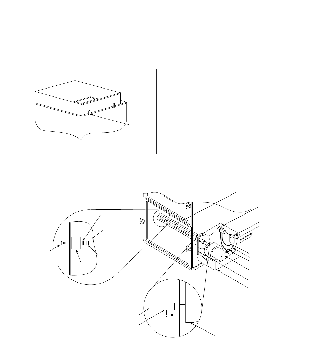
Chamber Silencer
Automatic Shaker
1. Place the chamber silencer over the clean-air
outlet on top of the unit.
2. Position silencer flush with the front of the unit
and the exhaust opening facing the front.
3. Secure with all four latches.
Front
latch
Chamber Silencer
The automatic shaker is driven by a 1/10 Hp
TENV gear motor controlled by a solid-state timer.
The timer control box can be ordered with or
without step-down transformers. A timer control
box without the transformer requires a 120-Volt
AC power supply controlled by a customer-supplied
fan starter. Input power is supplied to the timer on
fan motor shutdown, through the normally-closed
auxiliary contact of the fan starter. After a 60second delay, the timer energizes and the shaker
motor starts for a 30-second fixed time. Turning the
unit ON and OFF initiates the shaker sequence.
Wiring
1. Mount the timer control box in a convenient,
accessible location on or near the unit.
2. Complete the wiring to the fan starter, timer,
and shaker motor according to the appropriate
wiring diagram.
10-24 x 1 1/2-in
truss head screw
#10 lock
washer
shaker bar
10-24 hex nut
bearing bracket
assembly
1/2 x 5/8-in
coupling
shaker bar
shaker motor
relay
bracket clip
capacitor
red wire
blue wire
yellow/black wire
shaker motor
motor mount
shaker motor
cover
shaker bar
shaker motor
Automatic Shaker Installation
Page 25
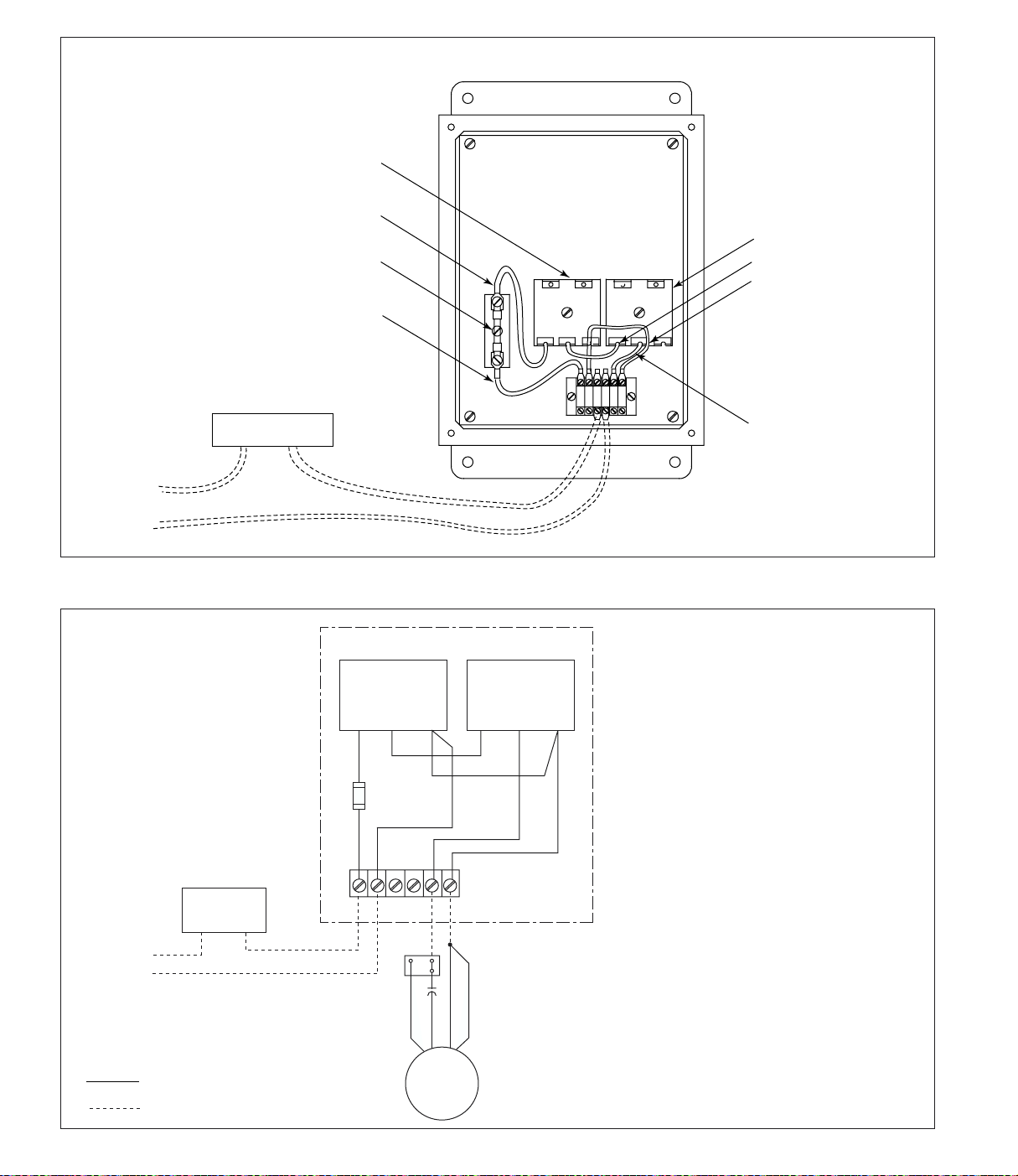
110-Volt
Power
Source
60-second
delay-on-make timer
red wire
fuse MDX 3 amp
red wire
fan starter
normally closed
auxiliary control
Series 50 to 80 Automatic Shaker without Transformer
30-sec interval timer
gray wire
gray wire
red wire
110-Volt
Power Source
Neutral in
grounded
systems
normally closed
auxiliary contact
at fan starter
Factory wired
Field wired
Electrical Control Box
delay timer
D1 D2 D3
4FU
3 amp
L1 L2 4 X2
red
blue
shaker
motor
interval timer
T1 T2 T3
black
yellow
Note: The automatic shaker requires a
120-Volt power supply controlled by
the fan starter. The normally-closed
auxiliary contact is supplied by others.
Solid-State Timer Specifications
Sequence of Operation
Input power is supplied to Terminals L1 and
L2 of the automatic shaker control. On fan
shutdown the normally-closed auxiliary
contact closes and power is supplied to the
solid-state timer which activates the delayon-make timer. After 60-seconds, the delayon-make timer energizes the interval timer
and starts the shaker motor. After 30-sec,
the interval timer times out and the shaker
motor turns OFF.
Input: 105 to 135-Volt AC, 50-60 Hz
Output: 700 Watts maximum load
Shaker Motor Specifications
Input: 105 to 135-Volt AC, 50-60 Hz
Output: 2.6 amp maximum load
Rating: Intermittent load, 1-min/Hour
Seriec 50 to 80 Automatic Shaker without Transformer Wiring Diagram
Page 26
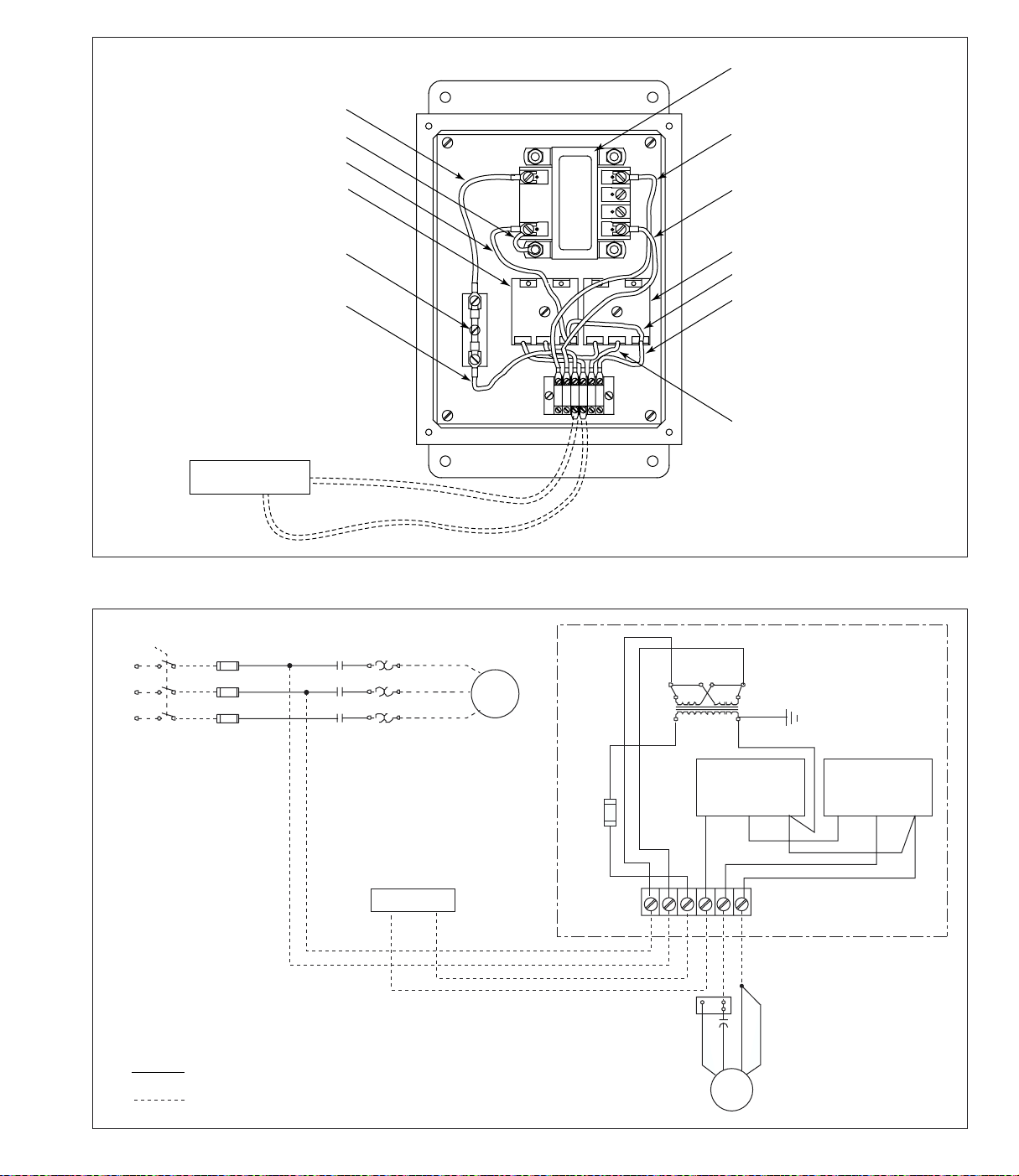
red wire
green wire
gray wire
60-second
delay-on-make timer
transformer
specify voltage
black wire
black wire
1L1
1L2
1L3
230/460V
60 Hz/3Ph
fuse MDX 3 amp
red wire
fan starter
normally closed
auxiliary control
1FU
L1
2FU
L2
3FU
L3
Series 50 to 80 Automatic Shaker with Transformer
1OL
1M
normally closed
auxiliary contact
at fan starter
1T1
1T2
1T3
fan
motor
4FU
3 amp
230V
H3
H1
X1
L1 L2 1 2 4 X2
H2
115V
delay timer
D1 D2 D3
30-sec interval timer
gray wire
gray wire
red wire
Electrical Control Box
H4
X2
interval timer
T1 T2 T3
105 to 135-Volt AC
50-60 Hz
Factory wired
Field wired
Seriec 50 to 80 Automatic Shaker with Transformer Wiring Diagram
blue
shaker
red
motor
black
yellow
Page 27

Preliminary Start-Up Check
Start-Up
1. Check all electrical connections for tightness
and contact.
2. Check for and remove all loose items in or near
the inlet and outlet of the unit.
3. Check that all remote controls are wired into
the control system, and all service switches are
in the OFF position.
4. Check that all optional accessories are installed
properly and secured.
5. Check that hopper discharge is open and the
storage container is sealed, if equipped. Excess
airflow to the blower will cause electrical
failure.
6. Turn power ON at source.
7. Turn the fan motor ON then OFF to check for
proper rotation by referencing the rotation
arrow located on the motor’s mounting plate.
To reverse rotation, single-phase power supply:
Follow manufacturer’s instructions on the
motor’s nameplate.
1. Turn power ON at source.
2. Turn unit ON.
3. On hopper models with 5- or 55-gallon drum
storage, check that hopper discharge is open
and the storage container is sealed, if equipped.
Excess airflow to the blower will cause
electrical failure.
4. When airflow diminishes, turn the unit OFF and
manually shake the EZ Filter Pack.
To reverse rotation, three-phase power supply:
Turn electrical power OFF at source and switch
any two leads on the output-side of the fanmotor starter.
Page 28
Service Information
EZ Filter Pack Installation
Step 1
B
D
E
Step 1
A. Remove top and bottom doors and set aside.
B. Remove and discard set screws and hold-down
channels.
C. Remove and discard envelope bags.
D. Clean bottom of cabinet ledge with stiff brush.
Note: The EZ Filter Pack seals against the
bottom of the cabinet ledge.
Step 2
B
C
Step 2
A. Remove banded EZ Filter Pack from box. Do
not remove bands.
B. Loosen wing screws fully.
C. Move slide latches back, away from the gasket.
E. Remove and empty dust drawer.
Step 3
Step 3
A. Insert banded EZ Filter Pack over shaker bar.
B. Cut and remove bands.
C. Remove cardboard protectors.
Step 4
Step 4
A. Insert one hand midway under each side of the
EZ Filter Pack.
B. Push EZ Filter Pack to bottom of the cabinets
filter frame.
Page 29

Step 5
Step 6
Step 5
A. Place one hand under the center of the EZ Filter
Pack.
B. Hold filter back against bottom of cabinet
ledge.
C. Push each slide latch over cabinet ledge.
D. Do not tighten wing screws at this time.
Step 6
A. Distribute filter envelopes evenly.
B. Finger-tighten wing screws.
Step 8Step 7
Step 7
A. Place support bar over center of EZ Filter Pack.
B. Insert small wing screws through holes in
support bar.
C. Hand tighten all wing screws.
Step 8
A. Inspect filter seal.
B. Replace clean dust drawer.
C. Replace cabinet doors and tighten securely by
hand.
Page 30

EZ Filter Pack Maintenance
Dust Disposal
1. Manually or automatically clean the filters
once each day depending on load
circumstances.
2. A good practice is to clean filters at break,
lunch, and end of day.
1. Turn unit OFF and empty dust container as
necessary to minimize dust in the hopper.
2. If the optional 5- or 55-gallon drum attachment
is used, empty when drum is 2/3 full.
3. If optional slide gate is used, close gate before
servicing drum.
4. Reinstall drum and open gate.
Page 31

Troubleshooting
melborP esuaCelbaborP ydemeR
rotomdnanafrewolB
tratstonod
egatlov
nwodtiucrictupnI llanotiucricrotomotylppusrewopkcehC
rotomdnanafrewolB
yatstonodtub,trats
gninnur
thgitdesolc
eziseriwrotomreporpmI deificepssaeguageriwtcerrocehtgnisueriweR
yltcerrocderiwtoNylppusrofgniriwrotomtcerrocdnakcehC
elbaliavarofderiwtontinU
nwodtiucricylppuslacirtcelE .egatlovreporproftiucricylppusrewopkcehC
dellatsniretrats-rotomtcerrocnI fiecalperdnaretratsrotomreporprofkcehC
tonronepoerasroodsseccA
nepoegrahcsidreppoH ottnemegnarrarevocmurdroetagedilsllatsnI
.sedoclacoldnalanoitanyb
gniriws'rerutcafunamrotomeeS.egatlov
ehtdnamargaidgniriwwolloF.margaid
.edoCcirtcelElanoitaN
.egatlovylppusreporprofgniriwtcerroC
.sdael
ecalpeR.tluafrekaerbtiucricroesufrofkcehC
.yrassecensa
.yrassecen
.sroodsseccanethgitdnaesolC
stnemhcattAreppoHeeS.egrahcsidreppoh
.11egaPno
lortnocrepmadnafrewolB
ylreporpdetsujdaton
.spmadetar
rotcellocrofegraloottelnI
.gnitar
daolrevotiucriclacirtcelE sahtiucricylppusrewopehttahtkcehC
.nosdlanoDtcatnoC
.tnempiuqellanurotrewoptneiciffus
lortnocrepmadtsujdA.tcudniwolfriakcehC
-rewolbehtdnadeveihcasiwolfriareporplitnu
s'rerutcafunamehtnihtiwsiwardpmas'rotom
Page 32

melborP esuaCelbaborP ydemeR
wolfriatneiciffusnI sdrawkcabnoitatornaF gnikoolnehwesiwkcolcsinoitatornafreporP
yranimilerPeeS.rotomrewolbehttanwod
.62egaPnokcehCpU-tratS
tonroneposroodsseccA
thgitdesolc
.11egaPno
detcirtseraeratsuahxenaF .snoitcurtsborofaeratsuahxenafkcehC
.lortnoc
dellifrevoaeraegarotstsuD
deggulpro
tcuddeggulprodespalloC .tcuddespallocecalpeR.sirbedllafotcudnaelC
gnizistcudreporpmI.ecnatsissarofnosdlanoDtcatnoC
deggulpkcaPretliFZE .yadaecnofomuminimaskcapretlifekahS
msinahcemrekahslaunaM
gninoitcnuflam
rekahscitamotuA
gnikrowtonmsinahcem
msinahcemni
sirbedrognidniblacinahceM
.92egaPno
.yrassecen
.msinahcemrekahseht
dnaecalpnierasroodsseccallatahtkcehC
egrahcsidreppohehttahtkcehC.deruces
stnemhcattalanoitpotahtdnadelaessigninepo
stnemhcattAreppoHeeS.yltcerrocdellatsniera
wolfrepmadtsujdA.sirbedrolairetamevomeR
lasopsiDtsuDeeS.aeraegarotstsudtuonaelC
deggulpskcapretlifnaelcyllaunamrohsurB
retlifecalpeR.lairetamsuorbifroykcitshtiw
.gnikahsybylreporpnaelctonodtahtskcap
.72egaPnonoitallatsnIkcaPretliFZEeeS
fiecalpeR.ecalpnisinipllorehttahtkcehC
morfsirbedronoitcurtsbonaelcdnakcehC
egatlovoN
remrofsnartehtot
.senilylppus
egatlovoN
remrofsnartehtmorf
.42egaPnomargaiDgniriW
slanimreTremrofsnarttaegatlovylppuskcehC
sesufkcehc,tneserpsiegatlovonfI.4Hdna1H
riaperdnakcehC.yrassecensaecalperdna
remrofsnarttatuptuotloV-511rofkcehC
,tneserpsiegatlovonfI.2Xdna1XslanimreT
rekahScitamotuAeeS.remrofsnartecalper
Page 33

Troubleshooting continued
melborP esuaCelbaborP ydemeR
rekahscitamotuA
gnikrowtonmsinahcem
deunitnoc
remitlavretnI taegatlovrofkcehc,yaleddnoces-06ehtretfA
roticapaC tupnis'roticapacehtotegatlovtupnikcehC
remitekam-no-yaleD ekam-no-yaledehtotegatlovtupnikcehC
,yaleddnoces-06ehtretfA.1DlanimreTs'remit
tupnifI.2DlanimreTnoegatlovrofkcehc
,egatlovtuptuoontub,tneserpsiegatlov
.remitekam-no-yaledehtecalper
egatlovtupnifI.1TlanimreTremitlavretnieht
.2TlanimreTtaegatlovtuptuokcehc,tneserpsi
siegatlovtuptuoonfiremitlavretniecalpeR
margaiDgniriWrekahScitamotuAeeS.tneserp
.42egaPno
yalerrotomrekahS .revocrekahsehtrednuyalerrotomehtetacoL
,4lanimreTs'yalerehttaegatlovtupnikcehC
tuptuokcehcdnayaleddnoces-06ehttiaw
ehtecalpeR.2lanimreTyalerehtnoegatlov
.tneserpsiegatlovtuptuoonfiyaler
rofkcehc,yaleddnoces-06ehtretfA.lanimret
egatlovtupnifI.lanimrettuptuoehtnoegatlov
ehtecalper,egatlovtuptuoontub,tneserpsi
gniriWrekahScitamotuAeeS.roticapac
.42egaPnomargaiD
rotomrekahsevitcefeD kcehC.rotomrekahsehtotegatlovtupnikcehC
fI.srotcennoclanimretnrowroesoolriaperdna
,doogerastnenopmocdna,slanimret,egatlov
rekahScitamotuAeeS.rotomrekahsecalper
.42egaPnomargaiDgniriW
tub,snurrotomrekahS
gniebtonsikcapretlif
denaelc
otseirtrotomrekahS
esufswolbtub,trats
gnissim
msinahcem
rabrekahsdnarotomrekahS
ro,esool,degamadgnilpuoc
.stnenopmocdegamad
rekahsnidegdolsirbeD
ehtevomerdnatiucriclacirtceletuokcoL
gnilpuocehttahtkcehC.ylbmessaroodmottob
rekahsehtotrotomrekahsehtstcennoctaht
ehtniswercstesehtnethgiT.erucessirab
ecalpeR.yrassecenfistalftfahsehtotgnilpuoc
ehtevomerdnaylppuslacirtceletuokcoL
evomerdnarofkcehC.ylbmessaroodmottob
dellatsnisikcapretlifZEtahtkcehC.sirbed
egaPnonoitallatsnIkcaPretliFZEeeS.ylreporp
tesehtgninesoolybrabrekahsehttsujdA.72
.rabrekahsdnarotomrekahsehtgniniojswercs
tenibacdnarabrekahsneewtebpagtsujdA
.esufecalpeR.swercstesnethgiT.yllauqesllaw
Page 34

Service Notes
etaD demrofrePecivreS setoN
Page 35

The Donaldson Torit Warranty
Donaldson Company, Inc. warrants to the original purchaser that for a period of ten (10) years from
the date of shipment, the product described herein shall be free from defects in materials and workmanship
if properly installed, maintained and operated under normal conditions. Donaldson Company makes
no warranty against damage due to corrosion, abrasion, normal wear and tear, modification or
misapplication and makes no warranty whatsoever as to any goods manufactured or supplied by
others. After Donaldson Company has been given adequate opportunity to remedy any defects in
material or workmanship, Donaldson Company retains the option to accept the return of the product,
with return freight paid by the purchaser, and to refund the purchase price for the product after
confirming the product is returned undamaged and in usable condition. Such a refund will be the full
extent of Donaldson Company’s liability and Donaldson Company shall not be liable for any other
costs, expenses or damages whether direct, indirect, consequential or otherwise. The terms of this
warranty may be modified only by a special warranty document signed by a Director, General Manager
or Vice President of Donaldson Company. Failure to use genuine Donaldson replacement parts will
cancel this warranty. THERE EXIST NO OTHER REPRESENTATIONS, WARRANTIES OR
GUARANTEES EXCEPT AS STATED IN THIS PARAGRAPH AND ALL OTHER WARRANTIES
INCLUDING MERCHANTABILITY AND FITNESS FOR A PARTICULAR PURPOSE, WHETHER
EXPRESS OR IMPLIED ARE HEREBY EXPRESSLY EXCLUDED AND DISCLAIMED.
For genuine Donaldson Torit replacement filters
and parts, call the Parts Express Line
For faster service, have unit’s model and serial number,
part number, description, and quantity available.
Donaldson Company, Inc.
Industrial Air Filtration
P.O. Box 1299
Minneapolis, MN 55440-1299
[email protected]
Parts and Service
800-365-1331
www.donaldsontorit.com
Donaldson Company, Inc. is the leading designer
and manufacturer of dust, mist, and fume collection
equipment used to control industrial-air pollutants.
Our equipment is designed to help reduce
occupational hazards, lengthen machine life,
reduce in-plant maintenance requirements,
and improve product quality.
© 2002 Donaldson Company, Inc. Printed in USA
 Loading...