

Page 1

BURR KING MFG. CO., INC.
1220 TAMARA LANE
WARSAW MO 65355
WWW.BURRKING.COM
(660) 438-8998 (800) 621-2748
FAX (660) 438-8991
January, 05
Dear Customer,
Thank you for purchasing the Burr King model 960-401/960-251 wet grinder. We are confident that it
will add value to your projects. Please note that the belt that is now on the machine (it is orange-brown
in color) is NOT
Do not use water on the belt we have provided to you with the machine, as it may fail to provide the
service you expect, and or physically fail.
Abrasive belts will vary in length, straightness, flexibility, etc. Because of this you need to be
particularly aware when you first install a new belt. If you do the following you will attain greater
satisfaction with each new belt:
Assure the grinder is securely bolted to a stable work surface.
Disconnect the AC electric power from your grinder.
• Push up on the rear wheel-tensioning handle and while holding the handle up push the red button
in the handle center to release the pawl from the ratchet.
• Lower to its lower most position the tensioning handle to remove tension from the old belt.
• Open the safety guard door
• Remove the old belt
• Install the new belt taking care that it is not bent, wrinkled, or otherwise deformed. The belt
should now be around the upper and lower wheel and be slack.
• Without pushing the red button push up on the tensioning handle. You will hear the pawl click as
the handle is moved upward. Push the handle back until you have heard 6 to 7 clicks.
• Manually rotate the belt on the wheels several rotations and see that the belt stays centered on the
wheels within about ¼ inch or less. If it does not, loose the locking handle on the tracking knob
located on the upper left of the machine. CW rotation of the tracking knob will move the belt to
the left, CCW to the right. Turn the knob ¼ turn in the required direction while manually rotating
the belt to observe the tracking effect. Adjust tracking as necessary.
• Close the machine guard door
• Connect the electric source.
• Momentarily engage the motor. The belt should run within ¼ inch of the wheel centers. If the belt
tracks within ¼ inch turn on the machine and slowly turn the tracking knob in the required
direction to fully align the belt.
• Secure the tracking knob locking handle
a wet capable belt.
See our catalog at www.burrking.com Contact us at us at [email protected]
DOC960-401NEWBELT-99 REV08/06
1
Page 2

This page intentionally
left blank
Page 3
MODEL 960-401
I
NSTRUCTION MANUAL
BURR KING MFG. CO., INC
1220 Tamara Lane
Warsaw, MO 65355
www.burrking.com
(660)438-8998 • 800-621-2748
Fax (660)438-8991
Model 30000 shown
with optional pedestal
BURR KING MODEL 960-401
WET GRINDER
Page 4

BURR KING MFG. CO., INC.
1220 TAMARA LANE
WARSAW MO 65355
WWW.BURRKING.COM
(660) 438-8998 (800) 621-2748
FAX (660) 438-8991
June, 2007
Burr King Manufacturing Company. Inc. warrants the below product to be free in material and workmanship. The period of warranty is 1 year
(90 days for vibratory bowls of 20 quart and lesser volume) from the date of purchase. No warranty is provided for products that have been
modified, abused, handled carelessly, where repairs have been made or attempted by others, or for freight damage. No warranty is provided for three
phase electric motors, cont rol lers, etc. when the motors, controllers are n ot protected by magnetic starters that were supplied and installed by Burr
King Manufacturing Company. Inc. No other warranty, written or verbal is authorized by Burr King Manufacturing Company, Inc.
During the warranty period Burr King Manufacturing Company, Inc (or its authorized suppliers or agents) will replace or repair the below
product without charge if the product is found by Burr King Manufacturing Company, Inc. to be defective. To receive warranty services you must
contact Burr King Manufacturing Company, Inc. and receive authorization fir warranty service. Unless otherwise authorized by Burr King
Manufacturing Company, Inc. Products (see * below) must be returned to the factory to receive warranty service.
*Motors, speed controllers, and certain other accessories are warranted by their resp ect ive manufactures. To receive warranty service on these
items you must contact a brand label service center that supports the product in need of service. Burr King Manufacturing Company; Inc. will assist
you in locating a service center.
For the first thirty days after purchase, and when Burr King Manufacturing Company, Inc. authorizes warranty service, we will pay normal and
necessary surface freight charges both ways (except for items in *). After thirty days the customer is responsible for all freight charges. Where
possible Burr King Manufacturi ng Company, Inc. may elect to make on site service and/or repairs necessary to return the product to serviceabl e
condition.
To assure prompt warranty service it is necessary that you complete and return the below warranty information to Burr King Manufacturing
Company, Inc. please FAX or MAIL at your convenience.
Product model: _______________________ Serial number: _______________________
Date Purchased: ______________________ Purchased from: ______________________
Address: ____________________________ City: _______________________State/Prov: _________Postal code________
Your company name: _____________________________________________
Address: _____________________________City: _______________________State/Prov: __________Postal code________
Phone: _______________________________Fax: _______________________Email: _______________________________
Your name: ___________________________Title: _______________________
How did you learn about Burr King products?
Trade show___Web___Industrial Distributor ___Advertisement ___Other __________________________Which one:________________________
What is the intended use of this product? ______________________________________________________________________________________
Please indicate the general work types performed at your company, check all that apply
Fabrication___Machining___Casting__Molding___Welding___Finishing___Assembly___Research___Other___
Please indicate the primary product focus of your company; check all that apply,
Aircraft/Missile___Automotive___Contract machine___Contract Fabrication___ Agricultural____Maintenance___ Recreational___
Job shop___Foundry___Construction___Arts___Orthopedic___Dental___Medical___Other_________________________________
Please tell us what we can do to improve our products
________________________________________________________________________________________________________________________
________________________________________________________________________________________________________________________
May we contact you? Yes___No___
Thank you for purchasi ng Burr King products!
:
:
Register online @
www.burrking.com
Page 5

(
)
(
)
(
)
August 29, 2007
BURR KING MFG. CO., INC.
1220 TAMARA LANE
WARSAW MO 65355
WWW.BURRKING.COM
660
438-8998
FAX
660
LETTER OF AUTHENTICITY
800
621-2748
438-8991
This letter is to certify that all Burr King Belt grinders, Disc
grinders, Polishing machines Vibra King Chambers and Bowls are
manufactured and assembled in the United States of America.
Tariff number 847990 criterion A )
(
Don Mac Carthy
President
See our catalog at www.burrking.com contact us at [email protected]
Page 6

BURR KING MFG. CO., INC.
1220 TAMARA LANE
WARSAW MO 65355
WWW.BURRKING.COM
(660) 438-8998 (800) 621-2748
FAX (660) 438-8991
February 2005
OPERATOR, and OPERATING AREA SAFETY
Subject equipment includes Grinders, buffers, polishers, and other rotating equipment. Serious injury
or death may occur if minimum safety precautions are not understood, and obeyed by operators and
those other persons who may be in the immediate vicinity of the subject equipment. Persons who
operate, or are in the immediate vicinity of the subject equipment must be properly trained in, and
use, minimum safety precautions and procedures for such machinery.
Minimum safety requirements to operate, or work in the immediate vicinity subject equipment:
1. Read and understand all operating instructions, manuals, labels, and other information provided with the
equipment.
2. Install the equipment according to manufacturer’s instructions.
3. Securely bolt the equipment to a rigid, structurally sound mounting surface.
4. Use and wear proper eye and face protection.
5. Use and wear proper protection for the body, hands, fingers, feet, and leg s.
6. Review and understand all machine guards, adjustments, and points of exposure to potential injury.
7. Do not remove, tamper with, or otherwise alter, equipment guards, and other safety features.
8. Insure the machine is adjusted, and remains adjusted according to manufacture’s requirements.
9. Maintain the equipment in good operating condition.
10. Have another person who is knowledgeable in proper and safe operation of the subject equipment
demonstrate proper and safe operation to all operators, and to those persons who might be in the immediate
vicinity of the subject equipment.
11. Use work piece holding devices when ever possible that diminish the possibility that persons will come
in contact with moving machine pieces, or spark/debris output from the machine.
12. Use spark and debris arresting apparatus. Such apparatus should be connected to the machine so as to
contain dust and debris that is generated, and to suppress sparks thereby limiting human inhalation risk, and
the risk of fire or explosion.
13. Use appropriate inhalation apparatus to protect person from ingestion and/or inhalation of sparks, debris,
smoke, particulates, etc.
14. Avoid mixing different metals, alloys, and materials. To mix such materials might create a fire or
explosion hazard.
15. Protect persons from work pieces, particulates, etc. that could be forcibly ejected from the machine. For
example, a buffing wheel or grinding belt can “grab” a work piece while the work piece is being buffed,
polished, ground, or otherwise conditioned, resulting in forcible ejection toward the operator or those in the
vicinity of the machine. The use of leather aprons, gloves, and eye shields are examples of protective gear
that may be effective. In general do not grind, buff, or otherwise engage the traveling belt, wheel, or disc
surface with the work piece pointing into the direction from which the belt, wheel, or disc is traveling.
However, if you choose to do so be aware the work piece may lodge in the traveling belt, wheel, or disc and
be forcibly, and dangerously ejected.
16. Do not operate this machine if the gap (nip point) between a moving belt, wheel or disc and the work
support surface exceeds 1/8 inch.
17. Do not operate this machine if the gap between the moving abrasive belt, disc or wheel and the adjacent
face
page 1 continued on next page
Page 7

Continued from page 1
of the work rest (or table) will permit passage of the work piece through the gap (nip point). Note, however,
that certain alloys such as titanium may create conditions where grinding debris can accumulate in a tight gap
creating a potential fire hazard. When in doubt consult with your safety officer. Failure to observe this
warning may result in the work piece or other item being caught in this gap, and/or being forcibly ejected.
Failure to heed this warning may cause serious bodily harm to the operator and/or bystanders. NEVER USE
THIS EQUIPMENT IF YOU ARE NOT PROP ERLY TRAINED IN ITS OPERATI ON and/or SAFE
USE! IF IN DOUBT STOP and ASK FOR GUIDANCE!
18. Never position the work rest table at an acute angle between the top of the work rest table and the moving
belt or wheel. Doing so will create “nip point” that can cause serious injury should an operator body part
become entangled (pulled into) the nip point created by this acute angle.
19. Do not operate the equipment, or allow others to operate the equipment without proper training in these
and other rotating machinery safety requirements.
20. Do not perform maintenance on the equipment unless you are fully qualified to do so, and understand all
necessary safety and operating requirements.
21. Do not leave the machine unattended while it is running.
22. Correct equipment or safety problems immediately. Do not operate the equipment when it requires
maintenance, or correction.
23. Install and use high quality abrasive belts, wheels, discs, media, etc., as appropriate to your machine.
Understand and follow the operating requirements provided by the manufacturer of these materials.
Rotational Speed Warning, Contact Wheels
Scope: Contact wheels manufactured by Burr King Manufacturing Company, Inc., which have rubber or
urethane tires. Examples include but are not limited to stock codes 202, 302, 402, 502,702, 802, 902, 1002,
1202 and variants. Variants have stock codes that begin with the base number; i.e. 802-S-55 is an 802
variant.
Users are warned not to exceed the below listed revolutions per minute (RPM) on the subject wheels. Failure
to heed this warning may lead to tire de-bonding, fragmentation, or other mechanical failure. Such failures
may cause serious personal injury to operators or bystanders, and/or cause property damage. All Burr King
products are warranted for various time periods to be free of material and/or workmanship defects. Burr King
Manufacturing Companies standard warranty policy is summarized as follows for contact wheels. 1 year
from date of purchase if mounted on a Burr King machine purchased on the same date or 90 days if
purchased as a spare or replacement part. Our warranty does not apply to wheels that are mounted on
products not manufactured by Burr King Manufacturing Company, Inc. Users who mount Burr King
manufactured contact wheels on product not manufactured by Burr King Manufacturing Company, Inc. do so
at their own risk and assume all liability for having so mounted the contact wheel(s).
Remember good safety practice demands guarding to protect operators and bystanders from wheel failure
and/or debris. Never use the subject contact wheels without proper guarding that meets commonly accepted
safe practice. See OSHA, U/L, CSA, CE, ISO and other respected
Stock code
Contact Wheel Maximum Safe RPM
202, 302 10000
402, 502, 702 802 4400
902, 1002 2200
1202 1600
Page 2, continued on page 3
safety standards.
Page 8

Continued from page 2
Occupational Noise Exposure
Burr King products produce levels of noise consistent with their intended purposes. The level and spectral
content of noise produced is dependent on the product type, the degree that the product is maintained in
proper operating condition, the abrasive/media and accessories used, the specific application, and the
surrounding environment. Noise levels produced by various Burr King grinders and polishers, as measured at
the Burr King factory, range from 80 to 93 decibels. Product operators and persons in the immediate product
vicinity should be protected from excessive noise does levels as prescribed in OSHA regulation 29, piece
1910.95 titled “Occupational Noise Exposure”.
ROTATING EQUIPMENT CAN BE DANGEROUS TO OPERATORS AND THOSE WHO MAY BE
IN ITS IMMEDIATE OPERATING VICINITY. IT IS THE ABSOLUTE AND DIRECT
RESPONSIBILITY OF PURCHASERS, MANAGERS, AND OPERATORS OF THIS EQUIPMENT
TO UNDERSTAND AND OBEY THE FOREGOING MINIMUM
REQUIREMENTS. IF YOU HAVE QUESTIONS OR SAFETY CONCERNS REGARDING
OPERATING THE SUBJECT EQUIPM ENT PLEASE CALL YOUR AUTHORIZED BURR KING
DISTRIBUTOR, OR BURR KING MANUFACTURING AT 1-800-621-2748. YOUR SAFETY IS
OUR FOREMOST CONCERN!
Burr King Manufacturing disclaims any and all responsibility for injuries, damage, loss of income, or other
adverse consequence as might be incurred by purchasers, managers, and operators of this equipment.
OPERATING SAFETY
Page 3
is last page
Page 9

BURR KING MFG. CO., INC.
1220 TAMARA
LANE
WARSAW, MO 65355
(660) 438-8998
(800) 621-2748
FAX (660) 438-8991
WWW.BURRKING.COM
s
Technical tip May 16, 2006
As you may know we improved many of our 120 and 220-volt single-phase variable speed grinders and
buffers to use a three-phase AC motor with an inverter controller rather than the DC motors and a rectifier
controller previously used. This change is transparent to the end user since the machine is “plugged in” to
single-phase outlets. The use of a three-phase motor permits the use of computerized “inverter” controls to
achieve variable speed control. Current technology does not support the use of single-phase motors for
variable speed operation except through the use of mechanical systems. We made this change for the
following reasons:
• Customers frequently demand excess horsepower output from the machines. Regardless of the “labeled”
horsepower electric motors can deliver power well in excess to stated capability for short periods of
time. Since there is “no free lunch” this excess horsepower is sustained by high current drain on the
supply service (what comes out of the wall). Further this high current drain taxes the control module on
the grinder or buffer and all interconnect circuitry such as the electrical cord which can get warm as
evidence of the overstress. The new configurations are more tolerant of excess horsepower demand.
• The DC motors and controllers previously used had fuses that would “blow” when the customer
demanded even short periods of overload necessitating the customer searching for and replacing up to
two fuses at the machine and perhaps having to reset an wall circuit breaker. The new configurations
are more tolerant of overload, but in the event of an overload the customer needs only to reset the
controller.
• The DC motors require the use of “brushes” that have a specified service life of about 1200 hours with
normal loading. Excess loading greatly reduces this time. The three-phase motors used with the new
configurations do not have brushes and are inherently more reliable.
• The DC controllers previously used are very limited in their ability to be interfaced with external
controls as might be found with robotics or other automation devices. The new AC controllers have
greatly expanded interface capability.
• The DC motors and controls were often limited in their ability to drive the machines to maximum
specified belt or wheel speed. The new configurations can be readily set for optimum advertised
speeds.
• The cost of modern inverter controls is now competitive with the cost of the older DC control modules;
and three-phase motors are very competitive with DC motors. This allows us to deliver a superior
value to our customers and to expand the application utility of our products without negatively
impacting the price that our customers pay.
Because of the common and widely used 120 volt single-phase service (your home, office, and in factories)
there are some important application aspects that you and our customers need to bear in mind. These apply
to the new variable speed configurations or for that matter any electrical motor driven machine where the
horsepower is 1-½ or greater. People often do not understand the electrical supply beyond “it comes out of
the wall” and “if it is my garage it must work on everything specified 120 volts, single phase”. Many homes,
offices, and even factories (in accordance with local and national codes) are wired with 14-guage feeder
wire to the 120-volt outlets making the supplied service inadequate for machines with 1-½ horsepower
See our catalog at www.burrking.com Contact us at [email protected] 1
Page 10

motors. To force these inadequate services to deliver power that is greater than their designed 15-ampere
capability leads to early equipment failure and potential fire danger. This must always be considered when
choosing the electrical supply.
• Burr King provides 1-½ horsepower, 120-volt machines with a 20-ampere power cables and
connectors. This is necessary to assure that the power cord does not dissipate excess energy (delivers all
available current to the motor), and to assure that the user plugs into a supply capable of delivering the
required 20 amperes of current. You can identify the 20-ampere cable by its 20-ampere plug that has a
90-degree orientation of the two flat blades. If a user defeats this performance and safety feature he
does so at his own hazard.
• At the application site you and our customer must assure 20-ampere service is used. Should the user
defeat the 20 ampere polarized plug provided by Burr King in favor of a 15-ampere service he may
experience nuisance circuit breaker trips.
• A 120 -volt, single phase 1-½ horsepower machine must always be connected to at least a 20-
ampere 120-volt source that incorporates 12-gauge wire at minimum. 20-ampere circuit breakers
must never be used with smaller than 12-gauge wire. Failure to observe this warning may create a
fire hazard and result in the loss of life and or property.
• It is common (by code and fact) to have five or more AC outlets wired to a single 20-ampere circuit box
breaker. This means that when a 20-ampere demanding device (1-½ horsepower motor) is connected to
one of the outlets no other device should be connected to the other shared outlets, in other words all of
the available current must be reserved for the 1-½ horsepower motor.
• 220-volt, single-phase 1-½ horsepower configurations should be connected to 15-ampere service.
Burr King machines are provided with appropriate power cables and connectors for this service
arrangement. Similar concerns exist for 220-volt, single-phase systems; however, 120-volt systems
are far and away of more concern and therefore require greater awareness and pro action.
• For 1-½ horsepower, 120-volt, single phase motor applications the use of extension cords should be
avoided. If it is necessary for an extension cord to be used assure that the cord does not exceed twenty
feet in length and is constructed with 12-gauge or larger wire. Failure to observe this will lead to
reduced performance, premature failure, and a potential fire hazard.
Remember that this is an important issue that effects product performance, reliability, and physical
safety. If you have doubts or need assistance call the factory. The new configuration machines will safely
deliver solid performance for many years provided they are supplied with and adequate AC power.
Finally, we think that you will agree the new configuration variable speed machines are a superior value
because of their improved reliability, improved tolerance to overloads, and extended capability!
See our catalog at www.burrking.com Contact us at [email protected] 2
Page 11

BURR KING MFG. CO., INC.
1220 TAMARA LANE
WARSAW MO 65355
WWW.BURRKING.COM
(660) 438-8998 (800) 621-2748
FAX (660) 438-8991
August 2002 Rev A
Operating instructions for the Model 960-401 wet belt grinder
The model 960-401 belt grinder is a two-wheel path belt grinder that uses a 2.5 or 4.0 x 60-inch continuous
loop abrasive belt. The grinder is intended for wet abrasive belt operation such as may be required for glass
finishing or lapidary work. For maximum effectiveness, and operator safety uses abrasive belts manufactured
by well-respected abrasive manufacturers.
• Use abrasive belts that are the proper size and type for your machine.
• Do not use abrasive belts that are old and excessively worn.
• Do not use abrasive belts that use lap splice joints. This type of belt is prone to separate. It also
may tend to snag your work and create a safety hazard. It may also perform poorly.
• Do not use metalized belts or other belts with sharp edges. Belts of these configurations could
present serious cutting injury potential to the operator or to bystanders should the belt
inadvertently leave the machine while the machine is in motion.
• Never touch or otherwise contact any portion of the abrasive belt while it is in motion. Doing so
could result in serious personal injury.
Prior to operating the model 960-401 please take time to do the following:
1. Insure that you have received all of the items that you ordered. Compare the packing slip with your
purchase order, and of course with the physical items received.
2. Verify that there is no obvious shipping damage. If shipping damage is discovered notify the freight carrier
of your intention to file a freight damage claim. They will assist you.
3. Verify that the AC power that is identified on the machine as received matches the AC power that you
intend to operate the machine with. Do not modify the machines wiring without first contacting your
distributor or Burr King manufacturing.
4. Do not modify or defeat any AC wiring safety feature. In example, do not remove the grounding pin on the
AC plug, or defeat the ground fault interrupt system if so equipped.
5. Verify that you have received a warranty card, parts lists, catalog, and Operator, and Operating Area
Safety Instructions.
6. Complete the warranty card and return it to Burr King Manufacturing.
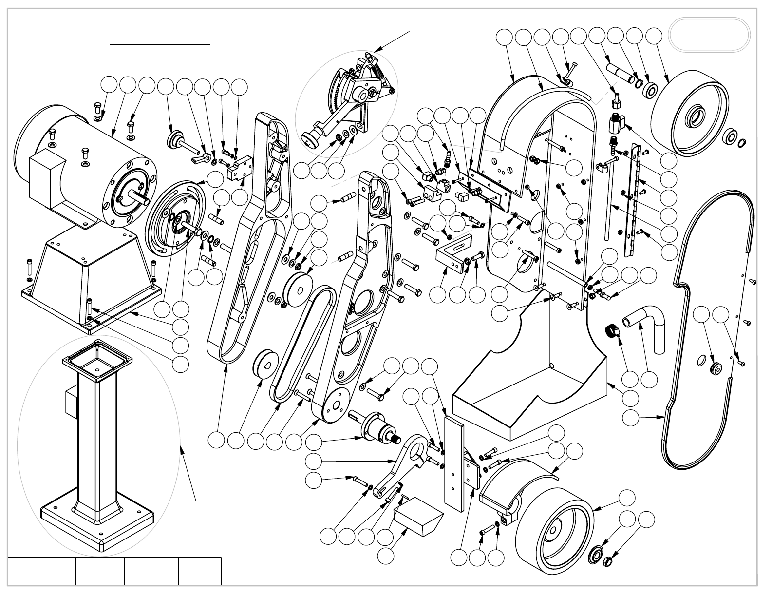
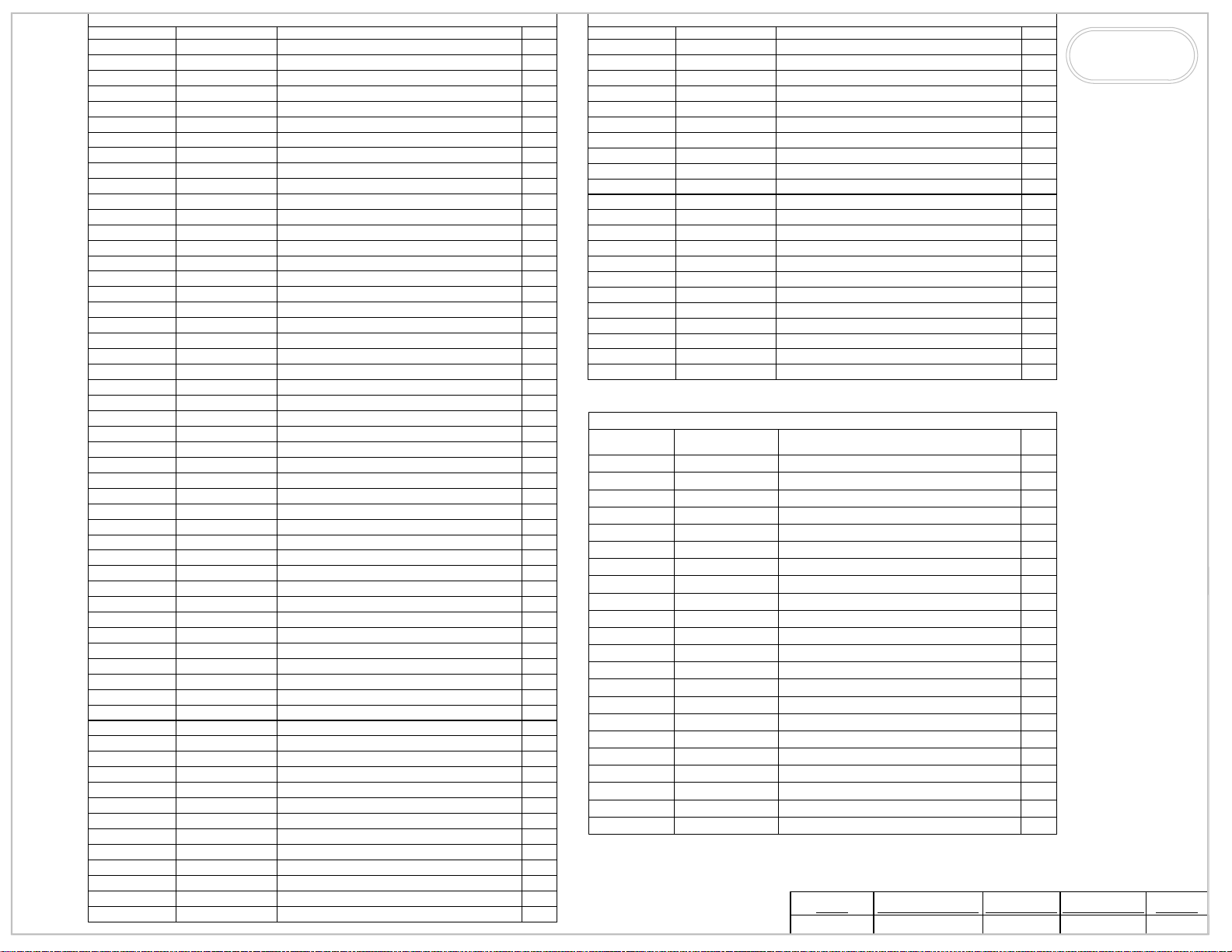
7. Verify that the various guards for the machine are in place and functional. See the parts list for the
indicated part numbers.
a. The contact wheel guard (903-4) is a mounted and adjusted such that pinch guard plate (914) if
used, is about 1/8 inch behind the abrasive belt and the contact wheel guard covers side of the contact wheel
(802-4) away from the operator. Where the pinch guard (914) is not mounted back-up platen assembly (904-
4) must be mounted to protect the pinch point that exists at the junction of the moving belt and the contact
wheel (804-4, i.e.). Burr King Manufacturing Company supplies one or both of these assemblies with each
machine shipped. FOR YOUR SAFETY DO NOT OPERATE THE 960-401 WITH THE PINCH
GUARD, BACK UP PLATEM ASSEMBLY OR ANY OTHER GUARD REMOVED OR NOT
PROPERLY ADJUSTED.
b. The full safety guard is in place, closed and its door latch is functional such that it will securely
hold the safety door closed (P/N 942A-1. 942-4B)
8. Prior to operating the model 960-401 read the Operator and Operating Area Safety Instructions
carefully. Insure that all persons who will operate the model 960-401, or who will work in the vicinity of the
model 960-401 read, understand, and comply with these instructions.
1
Page 12

9. Insure that the grinder is located in a work area that provides clear access to the machine such that
operators have clear and unobstructed access to the machine. The work place should be free from floor
obstructions, trip points, and other faults that may reduce operator safety.
10. Burr King recommends that all three-phase installations include a magnetic starter. Magnetic starters
protect motors from “single phasing”, overheating, etc. thereby reducing the risk of damage to the equipment
and/or fire hazard to your facility.
11. Insure that the model 960-401 AC power source is properly sized, and properly fused. You should
consult a competent electrician, or you may call Burr King Manufacturing for guidance.
Functional operating instructions for the model 960-401 belt grinder
The model 960-401 was fully tested and verified to comply with requirements prior to shipping from the
factory. You should perform the following steps in preparation for using the grinder:
1. With the machine securely bolted to its table, pedestal, and/or floor point connect the AC power to its
source.
2. Insure that the abrasive belt is tensioned properly. To do this, raise the tensioning handle (P/N 937G). You
will hear mechanical clicks as the tensioning ratchet pawl (737F) moves. Generally, the belt will be
adequately tensioned when you hear three to eight clicks. To reduce or release the belt tension slightly raise
the tensioning handle (P/N 737A) then press the button (P/N 737B) in the center of the tensioning handle.
Move the tensioning handle down slightly to reduce belt tension or all the way down to release belt tension.
4. Engage the motor by placing the ON/OFF switch to ON. The belt should rotate smoothly
in a CCW
direction about the machine wheel belt path as you face the right side of the machine. If either of these
conditions is a not met turn the machine OFF immediately.
a. If the abrasive belt does not remain centered on the contact wheel (802-4) while the belt is moving
use the tracking adjustment (P/N 921-4) on the upper left side of the machine to track the belt. Turning this
control CW to causes the belt to track to the right, conversely turn the control CCW to causes the belt to
move to the left.
b. If the belt runs in reverse ( up from the floor) you must correct this by changing the main drive
motor rotation direction. A COMPETENT ELECTRICIAN SHOULD PERFORM ALL ELECTRICAL
WORK ON THE MODEL 960-401.
1) Reversed the motor direction of a three-phase motor by reversing any
two legs of the input power lines.
2) Reverse the motor direction of a single phase motor by reversing leads 5 and 8 found
within the metal wiring box located on the motor, or as otherwise instructed on the actual
motor label.
c. If the machine belt tensions, and tracks properly, but has excessive vibration turn the machine OFF
and call the Burr King factory for assistance.
Belt speed
The 960-401 will operate at two different belt speeds (fixed speed model). It is shipped from the factory in
the high-speed mode of approximately 4700 surface feet per minute (SFPM). To change to the lower belt
speed of approximately 2100 SFPM it is necessary to reverse the drive pulleys. To do this first remove
electrical power ten:
• remove the rear idler wheel
• remove the pinch guard
• remove the main belt guard
• locate the hex head bolts that secure the two halves of the main frame together, support the frame
and remove these bolts.
• loose the two elastic hex bolts that secure the motor side of the frame to the motor, do not
remove these.
• remove the v-belt
• remove and reverse the v-pulleys taking care to align them so that the v-belt tracks true and the
pulleys do not drag the frame.
• reassemble
• tighten the v-belt and secure by tightening the elastic nuts.
2
Page 13

• check for proper operation
Using the water system that is part of the 960-401 grinder.
The 960-401 is equipped with a re-circulating water fed system that is intended to bath the abrasive belt,
gather in the water, and return the water and grinding slurry into a pail.. The system consists of:
• one 5 gallon pail
• one low pressure pump
• one stainless steel pump bracket
• one metering valve
• two spray nozzles
• one stainless steel fluid gathering tray
• necessary tubing, connections, etc. to permit fed and drain of the water and slurry.
The water system is intended ONLY for water. Do not substitute other solvents they may create a fire,
electrocution, or chemical hazard to operator and/or the equipment.
Operation of the water fed system is simple.
• Adjust the water flow to the desired volume by using the valve located on the rear of the
machine guard.
• The water spray is factory adjusted to address the abrasive belt when the machine is operated in
any attitude from a horizontal to a vertical belt track position.
• The water is returned into the pail via the gathering tray and its associated drain hose that
extends to the water pail.
• The water deliver system and the recovery drain apparatus is designed to work in any machine
position from a horizontal to a vertical belt angle.
NEMA 4 electrical system
The 960-401 wet grinder is factory equipped with a motor, switch, and cord that are NEMA 4 rated for wet
operation. This means that they may be used in wet locations, but not in locations where flooding of the
equipment is probable. The 960-401 also is equipped with a ground fault interrupt plug, and a central
ON/OFF switch mounted in a “rain” type electrical box intended for mounting away from the wet abrasive
belt location. AVOID ELECTICUTION, DO NOT MODIFY OR DEFEAT THE NEMA 4
ELECTRICAL SYSTEM. If your 960-401 requires electrical work insure that a qualified electrician who
understands NEMA 4 requirements performs the work.
In the event the GFI circuit breaker open circuits you must investigate for and correct the problem. Failure
to correct an electrical ground fault condition may result in electrocution
Maintenance for the model 960-401
FIRST DISCONNECT THE MACHINE FROM ITS AC POWER SOURCE.
* Every thirty days check the v-belt (P/N 429) tension. If you can hear the belt “slap” the v-belt guard (P/N
928-4) when the drive motor starts, the v-belt may require re-tensioning. Do this by loosening the two nuts
(P/N 39) that secure the motor to the v-belt guard (P/N 928-4) and slide the guard forward. Tighten the two
nuts (P/N 39).
* Daily vacuum or otherwise remove dust and debris build-up from the machine and the machine belt track.
* Routinely inspect for loose screws and other hardware and tighten as required.
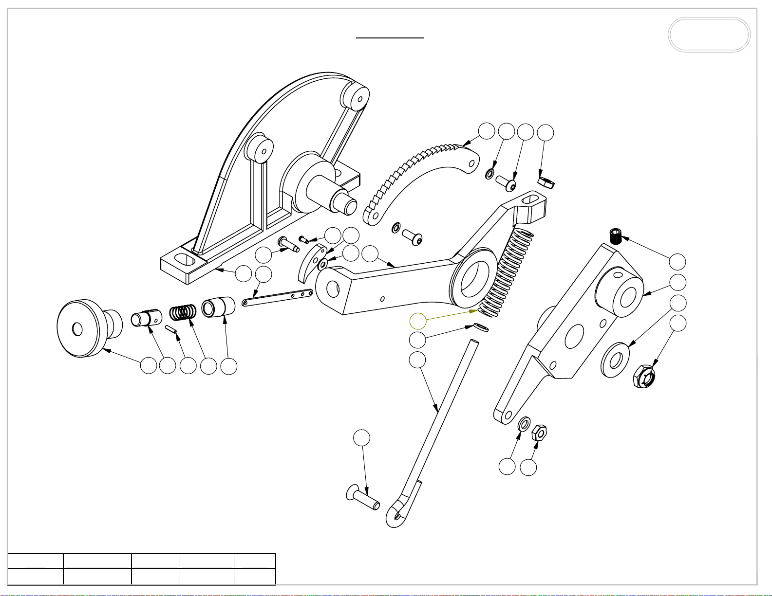
* If the rear wheel assembly (945) does not operate smoothly it may require lubrication. To re-lubricate you
must disassemble the 945, clean it with a mild solvent, and greaser it lightly with a good grade of marine
bearing grease such as NLGI type GC-LB intended for water bathed applications. Do not use ordinary
bearing grease as the water used in your glass(i.e.) grinding process will dilute the grease making it
ineffective.
There are a no other maintenance actions required. All bearings is a sealed for life and require no additional
lubrication.
------------------------------------------------------------------------------------------------------------
3
Page 14

Remember for operator safety and the continued effectiveness of your model 960-401:
Do not defeat the safety guards and other safety provisions of the model 960-401.
Do not operate the model 960-401 with the safety guard open or the contact wheel guard/platen
assembly (or internal grinding attachment) removed.
Do not reach inside the safety guards while the machine is running. To do so is hazardous.
Do not uses fluids in your grinding process unless your model 960-401 is designed for liquid operation
(NEMA 4, 4X). To do so may create an electrical safety hazard.
Do not uses your model 960-401 to grind/polish explosive materials such unless it is equipped with
explosion proof electrical devices and motor.
Do not mix alloys in your grinding. To do so may create an explosion hazard.
Do not use stone or vitreous wheels on the model 960-401. To do so will create an operator safety
hazard.
Do uses eye, hand, face, arm, leg, feet and body protection that is adequate to protect against flying
debris, forcibly ejected work pieces, broken abrasive belts, etc.
Do train operators and others in safe operating practices.
Post these or equivalent instructions such they are available for ready operator reference.
Burr King Manufacturing can help you with problem solutions, and/or answers to your questions. Please call your Burr
King distributor first. If you can not reach satisfactory conclusion please call the Burr King factory, telephone 1-660438-8998.
4
Page 15
M960-401
SCHEMATIC
1
2
3
4
5
945S
7
6
8
34
3736
38
51
52
53
54
55
56 57
58
59
BURR KING
1220 TAMARA LANE
WARSAW, MO. 65355
33
39
41
35
42
43
45 46 47
40
13
44
13
41
48
49
60
63
60
61
64
43
63
66
67
65
69
73
74
75
76
52
77
78
79
30
31
25
9
16
18
17
14
15
14
10
9
11
12
13
26
17
9
25
27
32
1
DATE DRAWN
9/25/2009
REV DATE
DRAWN BY
CMW
19
20
21
SEE PAGES 4 & 5
FOR ELECTRICAL
SHEET
1 OF 6
22
19
23
24
12
13
12
13
28
29
50
12 13
13
41
62
70
71
68
72
Page 16
85
86
87
945-4S
89
88
90
91
95
96
79
97
BURR KING
1220 TAMARA LANE
WARSAW, MO. 65355
98
99
100
TITLE
M960-401
DATE DRAWN
9/25/2009
80 81
REV DATE
82
83
84
DRAWN BY
CMW
SHEET
2 OF 6
92
13
94
?
13
97
101
Page 17
ITEM NO.
1 4
2
3
4
5 922
6
7
8
9
10
11
12 31
13
14 42
15
16
17
18
19
20
21
22
23
24
25 39
26 40
27
28
29
30 3569
31 3571
32
33 3570
34 3572
35 3568
36
37
38 3577
39
40
41 30
42
43
44
45
46
47
48
49
50
51
52 3408
53 3578
54
55 3340
56
57
PART NUMBER
MOTOR
37
921-4
18
2-0023
5-0035
17
1-0003
941
5
5-0014
908
920
923-4
900-4
725
429K
6
701
705-1
730
6-0014
706-1
1-0035
3577-3
3-0026
1-0019
904A
209
4-0013
5-0032
924
4-0009
1
2-0011
3-0039
904B
942-4S
3-0036
707c
701F
M960-401
BOLT, 5/16-18x3/4 HH, GRD5, PLTD
WASHER, #10, LOCK, HIGH COLLAR
SCREW, 1/4-20x1 1/4 SOC CAP
WASHER, 3/8, LOCK, INTERNAL STAR
SCREW, 1/4-20 x 1 1/2 FH ALLEN
BEARING, CONTACT WHEEL ASSY
ELBOW, STREET, EXTRUD, 1/8NP
BOLT, 1/4-20 x 1.25, SOC CAP SS
BARB, 1/8MP TO 1/4 TUBE, BRASS
SCREW, 8-32 x 1, FLATHEAD, PHILLPS, SS
BOLT, 5/16-18x1 1/2 HH, CS, ZN PLTD
WASHER, 1/4, LOCK, SPLIT, PLTD
BOLT, 5/16-18x1, HH, GRD 5, PLTD
SCREW, 1/4-20 x 3/4, S/S FH SCS
TUBING, CLEAR, FLEXIBLE, 1/4ID
SCREW, 10-32 X 1 1/4 ALLEN CAP
RING, RETAINING, 5/8 EXTERNAL
DESCRIPTION
WASHER, 5/16 SAE ZINC PLTD
CALL FACTORY
KNOB, TRACKING ASSY
LOCK, KNOB, TRACKING
WASHER, 960-516, AN
SCREW, 10-24 X 5/8 SC ALLEN
WASHER, 960-616, AN
BOLT, 3/8-16 x 1 1/4 HEX HEAD
BASE
WASHER, 960-416, AN
WASHER, 3/8,THRU-HARD, YZ
ADAPTER, C-FACE MOTOR
STUD 3/8"x1 1/2", DOUBLE
BRACKET, TRACKING
FRAME/GUARD, ASSEMBLY
PULLEY, 2 1/2"
BELT, V, NOTCHED, 4L240
ARM, WORKREST SUPPORT
NUT, 3/8-24, JAM, ESNA, NTE
WASHER, 3/8, SAE, PLTD
PULLEY, 3"
PIN, 1/8 X 3/4, ROLL
WORKREST, ANTI-TILT
BLOCK, SECURING
TEE, BRASS, EXTRUDE, 1/8NPTF
NOZZLE, SPRAY, BRASS, V8NPT
BRACKET, BRUSH RETAINING
FELT
PLATEN, BACKUP
SCREW, 1/4-20x1 SHCS
SCREW, 1/4-20 X 3/4 SHCS
NUT, 1/4-20, KEP
SUPPORT, BACKUP
NUT, 5/16-18, JAM, PLTD
SCREW, 1/4-20 X 1.5 SOC CAP
BRACKET, PLATEN
GUARD, SAFETY, PAINTED
CLAMP,3/8OD, PLS. HOSE
BARB, HOSE, FM, 1/4H x 1/4F
SHAFT, BEARING
QTY.
10
1
4
1
1
1
3
3
6
2
1
7
12
4
2
1
4
1
1
1
1
3
1
1
4
1
1
1
1
2
1
2
1
1
2
1
3
1
6
1
5
1
2
1
1
1
1
3
3
1
1
1
2
2
1
1
2
ITEM NO.
58
59
60
61 23
62
63
64
65
66 3406
67
68
69 3409
70
71
72
73 3337
74 3339
75
76 14
77 24
78
79
ITEM NO.
80
81
82 26
83
84
85
86 27
87
88 28
89
90
91
92 34
93
94
95
96 15
97
98 25
99
100
101
PART NUMBER
701B
907
4-0025
903
4-0022
942C-4
742L1
DF4-1
942B-1
802
726
727
742E
742H
9
M960-401
CONTACT WHEEL, 7x2.5, 55 DURO
VALVE, LOW PRESSURE, 1/4 NPT
GROMMET, SAFETY GUARD DOOR
SCREW, 10-24x1/2 BH, BLK OXIDE
DESCRIPTION
BEARING
WHEEL, IDLER
NUT, 8-32, ELASTIC, STOP, SS
NUT, 6-32, KEP, PLTD
GUARD, CONTACT WHEEL
NUT, 1/2-20, NYLOK, SS
STANDOFF, DOOR
LATCH, STUD, CLEAR ZN PLTD
CLAMP, HOSE, 7/16" TO 1"
SCOOP, FLUID, SS
DOOR, GUARD
HOSE, STL. REINF., 5/8ID VIN
FLANGE, OUTER WHEEL
NUT, 5/8-18 RH, JAM, BRT PLT
BARB, ML, HOSE, 1/4H x 1/4M
HINGE, GUARD TO DOOR
NUT, 10-24, KEP
SCREW, 6-32 x 1/2, MACH
945-4S
PART NUMBER
737A
737B-1
737D
737E
940
937BA
737F
5-0027
937G
989
939
736
3
935
21
20
WASHER, #8,18-8 STAINLESS STEEL
SCREW, 5/16-18 x 3/8, SET, SOC
DESCRIPTION
KNOB, HANDLE
BUTTON
PIN, 3/32 x 3/8, ROLL PLTED
SPRING, REAR WHEEL ASSY
NIPPLE, HANDLE
SUPPORT, IDLER WHEEL
SCREW, #8 X 5/8, DRIVE
STRIP, BUTTON ASSEMBLY
SCREW, #2 x 1/4, DRIVE
PAWL
HANDLE
SCREW, 1/4-20 X 1, FH PHILLIPS
SPRING, BELT TENSION
GUIDE, SPRING
SECTOR
WASHER, #10, LOCK
NUT, 1/4-20 JAM, PLTD
SUPPORT, REAR WHEEL
WASHER, 1/2 SAE, FLAT, ZINC
NUT, 1/2-20, JAM, ESNA, NTE
* USES A 011D TOGGLE SWITCH
TITLE
M960-401
DATE DRAWN
9/25/2009
QTY.
2
1
5
3
1
5
1
1
1
1
1
1
1
1
1
1
1
1
3
3
1
3
QTY.
1
1
1
1
1
1
1
1
1
1
1
1
1
1
1
1
2
2
1
1
1
1
REV DATE
BURR KING
1220 TAMARA LANE
WARSAW, MO. 65355
DRAWN BY
CMW
SHEET
3 OF 6
Page 18
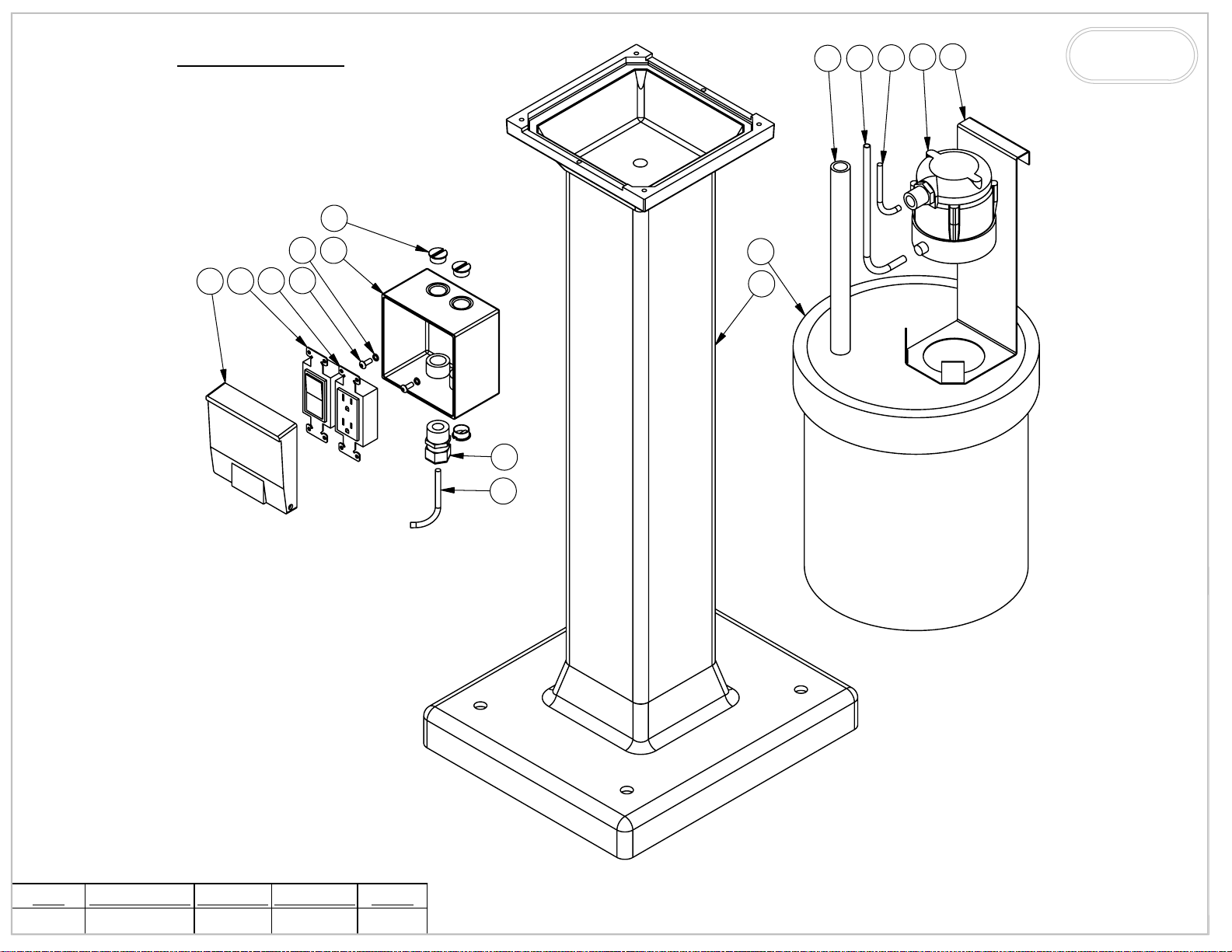
115 SET UP
6
69 52
13
12
9
BURR KING
1220 TAMARA LANE
WARSAW, MO. 65355
4 7
5
3
2
1
8
9
10
11
TITLE
M960-401
DATE DRAWN
9/25/2009
REV DATE
DRAWN BY
CMW
SHEET
4 OF 6
Page 19
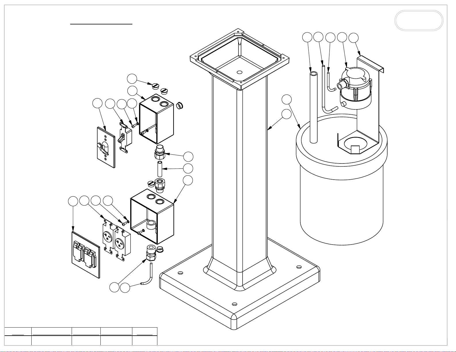
220 SET UP
5
6
3
BURR KING
1220 TAMARA LANE
52
69
7
8
4
11
12
13
14
15
10
16
17
WARSAW, MO. 65355
TITLE
M960-401
DATE DRAWN
9/25/2009
2
1
REV DATE
3
4
DRAWN BY
CMW
9
10
SHEET
5 OF 6
Page 20
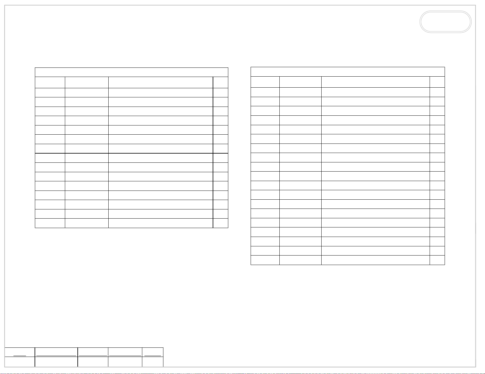
BURR KING
1220 TAMARA LANE
WARSAW, MO. 65355
ITEM NO.
1 9952
2 9951
3 9950
4 15
5 9
6 9902
7 3326
8 3356
9 015
10 3317
11 02
12
13 3331
52 3408
69 3409
PART NUMBER
3316-3
115V SET UP
DESCRIPTION
COVER, 2 GANG RAYNTITE,5045-0
SWITCH, ROCKER, 15A, 120V,
RECEPTACLE, GFI, DUPLEX, 120V
WASHER, 5/16 LOCK, SPLIT
SCREW, 10-24x1/2 BH, BLK OXIDE
PLUG, 1/2" CONDUIT
BOX, WP, 2 GANG, DEEP
RELEIF, STRAIN, 1/2"
CORD
PAIL, 5 GAL. PLASTIC, BLACK
PEDESTAIL
PUMP, WATER/120V/1PH/60HZ
BRACKET, PUMP HANGER
TUBING, CLEAR, FLEXIBLE, 1/4 ID
HOSE, STL. REINF. 5/8 ID VIN
QTY.
1
1
1
2
2
3
1
1
2
1
1
1
1
1
1
ITEM NO.
1
2
3 9
4 15
5 3325
6 3323
7 9902
8 3354
9 3356
10 017
11 775
12 020
13 3326
14 3317
15 02
16
17 3331
52 3408
69 3409
PART NUMBER
3567-2
3329-1
3316-1
220V SET UP
DESCRIPTION
COVER, 2 GANG, 2 SGL, RCPT, WP
RECP, 20A SINGLE 250V
SCREW, 10-24x1/2 BH, BLK OXIDE
WASHER, #10 LOCK
COVER, SINGLE, LEVER, RAIN
SWITCH, TOGGLE
PLUG, 1/2" CONDUIT
BOX, WP, SINGLE, DEEP
RELEIF, STRAIN, 1/2"
CORD
CONNECTOR, 3/8" STR, LIQ. TIGHT
CONDUIT, 3/8", LIQ. TIGHT
BOX, WP, 2 GANG, DEEP
PAIL, 5 GAL. PLASTIC, BLACK
PEDESTAIL
PUMP, WATER, 220V/1PH/50-60HZ
BRACKET, PUMP HANGER
TUBING, CLEAR, FLEXIBLE, 1/4 ID
HOSE, STL. REINF. 5/8 ID VIN
QTY.
1
2
4
4
1
1
5
1
1
2
2
1
1
1
1
1
1
1
1
TITLE
M960-401
DATE DRAWN
9/25/2009
REV DATE
DRAWN BY
CMW
SHEET
6 OF 6
 Loading...