

Page 1

MODEL
960-272
I
NSTRUCTION
MANUAL
BURR KING MFG. CO., INC
1220 Tamara Lane
Warsaw, MO 65355
www.burrking.com
(660)438-8998 • 800-621-2748
Fax (660)438-8991
BURR KING MODEL 960-272
TWO WHEEL GRINDER
Page 2

BURR KING MFG. CO., INC.
1220 TAMARA LANE
(660) 438-8998
(800) 621-2748
FAX (660) 438-8991
Re gis ter o nli ne @
w w w. bu r r k i ng . co m
WARSAW MO 65355
WWW.BURRKING.COM
June, 2007
Burr King Manuf acturing Company. Inc. warrants the below product to be free of defects in material and workmanship. The period of
warrant y is 1 year (90 days for vibratory bowls of 20 quar t and lesser volume) from the date of purchase. No warranty is provided for
products that have been modified, abused, handle d carelessl y, where repairs have been m ade or attempted by ot hers, or for freight damage.
No warranty is provided for three phase electric motors, controllers, etc. when the motors, controllers are not protected by magnetic start ers
that were supplied and installed by Burr King Manufacturi ng Company. Inc. No other warranty, written or verbal is authorize d by Burr
King Manufact u ring Company, Inc.
During th e w arranty peri od Burr King Manufa cturing Company, Inc (or its authorized suppliers or agents) will replace or repair the below
product without char ge if the product is f ound by Burr King Manufacturing Company, Inc. to be defective. To receive warranty se rvices you must
contact Burr King Manufacturing Company, Inc. and rec eive authorization fo r w arranty ser vice. Unless otherwise aut horized by Burr King
Manufacturing Company, Inc. Products (see * below) must be returned t o the factory t o receive warranty service.
*Motors, speed controllers, a nd certain other accessories are warranted by their respective ma nufacture. To receive warranty service on these
items you must contact a brand label ser vice center t hat supports t he product in need of service . Burr King Manufac turing Company; Inc. will as sist
you in locating a servic e center.
For the first thirty days afte r purchase, and when Burr King Manufacturing Company, I nc. authorizes warr anty service, we will pay
normal and necessary surf ace freight charges both ways (except for it ems in *). After thirty days the customer is res p onsible for all freight
charges . W here possible Burr King Manufacturi ng C om p any, Inc. may elect to make on site servic e and/or repairs necessary to r e turn the
product to serviceable condition.
To assure prompt warranty service it is necessary t hat you complete and return the below warranty information to Burr King Manufacturing
Company, I nc. please FAX or MAIL at your conve nience.
Product m odel: _______________________ Serial number: _______________________
Date Purchased: ______________________ Purchased from: ______________________
Address: ____________________________ City: _______________________State/Prov: _________Postal code________
Your company name: _____________________________________________
Address: _____________________________City: _______________________Sta te/Prov: __________Postal code________
Phone: ___________________ ____________Fax: _______________________Email: _______________________________
Your name: ___________________________Title: _______________________
How did you lea rn about Burr King pr oducts?
Trade show ___Web___Indus trial Distributor ___Advertiseme nt ___Other __________________________Which one:________________________
What is the intended use of this product? ________ ____________ __________________________________ ________________________________
Please indicate the general work types performed at your company, check all that apply
Fabrication___Machining___Casting__Molding___Welding___Finishing___Assembly___Research___Other___
Please indicate the primary product focus of your c o m pany; check all that apply,
Aircra ft/Missile ___A utomotive___Contrac t m achine___Contr act Fabrication___ Agricultural____Ma intenance___ Recreational___
Job shop___Foundry___Constructi on___Arts___Orthopedic___Dental ___M edical___Other_____________ ____________ ________
Please tell us what we can do t o im prove our products
________________________________________________________________________________________________________________________
________________________________________________________________________________________________________________________
May we contact you? Yes___No___
Thank you for purchasing Burr King products!
:
:
Page 3
BURR KING MFG. CO., INC.
(660) 438-8998
(800) 621-2748
FAX (660) 438-8991
April 2, 2009
1220 TAMARA LANE
WARSAW MO 65355
WWW.BURRKING.COM
LETTER OF AUTHENTICITY
This letter is to c ert ify tha t a ll B urr King Belt grinde rs , Disc grinders, Polish ing
machines Vibra King Chambers and Bowls are manuf a ctu red and assemb l ed in the
United S ta tes of America.
Tariff number 847990 criterion A)
(
Don Mac Carthy
President
See our catalog at www.burrking.com contact us at [email protected]
Page 4

BURR KING MFG. CO., INC.
(660) 438-8998
(800) 621-2748
FAX (660) 438-8991
RE A D AN D S AV E A LL IN S T R U C T I O N S FO R F UT U R E R E FE RE N CE
1220 TAMARA LANE
WARSAW MO 65355
WWW.BURRKING.COM
960-272 Important Safety Instructions
OPERATOR, and OPERATING AREA SAFTEY
WARNING!
WHEN USING ELECTRIC TOOLS, BASIC SAFTEY PRE CA US TIONS
SHOULD ALWAYS BE FOLLOWED TO REDUCE RISK OF FIRE,
ELECTRIC SH O CK AND PERS O NAL INJUR Y.
Subject equipment includes Grinders, buffers, polishers, and other rotating equipment. Serious injury or death
may occur if minimum safe ty precautions are not unders tood, and obey ed by operators and those ot her persons
who may be in the immediate vicinity of the subject equipment. Persons who operate, or are in the immediate
vicinity of the subject equipment must be properly trained in, and use, minimum safety precautions and
procedures for s uch machinery.
1. READ ALL INSTRUCTIONS
• Read and understand all operating instruction, manuals, labe ls, a nd other information provided with the equipment.
2. KEEP WORK AREA CLEAN
• Cluttered areas and benches invite injuries.
3. CONSIDER WORK AREA ENVIRONMENT
• Do Not expose power tools to rain
• Do Not use grinder in damp or wet locations.
• Keep work area well lit.
• Do Not use grinder in presence of flammable liquids or gases
4. GUARD AGAINST ELECTRICAL SHOCK
• Prevent body contact with grounded surfaces. For example: pipes, radiators. Disconnect from power source when
not in use. Never use if electrical cord is damaged or wet. Always keep electrical cords clear of rotating parts and belt
while in motion. Electrical installation shall be in accordance with applicable codes and regulations.
5. KEEP CHILDREN AWAY
• Do Not let visitors contact tool or cord
• All visitors should be kept away from work area
6. DRESS PROPERLY
• Do Not wear loose clothing or jewelry.
• Non-Skid footwear is recommended when working with equipment.
• Wear protective hair coverings to contain long hair.
• Wear proper attire to protect eye, hand, face, arm, leg, feet and body that is adequate to protect against flying debris,
forcibly ejec ted work pieces, broken abrasive belts, ect.
Page 5

7. USE SAFETY GLASSES
• Everyday eyewear does not feature impact resista nce lenses, and they are NOT safety glasses
8. WEAR DUST MASK
• Some dust created by grinding activities may contain chemicals known to cause cancer, birth defects or other harm.
Provide adequate ventilation.
9. SPARK AND DEBRIS ARRESTING APPARATUS
• To further reduce the exposure you may wish to connect an apparatus to the machine to contain dust and debris/spark
arresting devic e to suppress sparks thereby limiting human inhalation risk, and risk of fire or explosion
10. KEEP ALL GUARDS IN PLACE AND PROPERLY ADJUSTED
• Keep all guards in place and in working order.
• Do not reach inside the safety guards while the machine is running.
• Do not operate this machine if the gap (nip point) between a moving belt, wheel or disc and the work support surface
exceeds 1/8 inch or 3.175 mm
• Never position the work rest table at an acute angle between the top of the work rest table and the moving belt or
wheel. Doing so will create “nip point” that can cause serious injury should an operators body part become entangled
(pulled into) the nip point cr eated by this acute angle.
• Do not operate this machine if the g ap between the moving abrasive belt, disc or wheel and the adjacent face of the
work rest (or table) will permit passage of the work piece through the gap (nip point). Note, however, that certain
alloys such as titanium may create conditions where grinding debris can accumulate in a tight gap creating a potential
fire hazard. When in doubt consult with your safety officer. Failure to observe this warning may result in the work
piece or other item being caught in this gap. And/or being forcibly ejected. Failure to heed this warning may cause
serious bodily harm to the operator and/or bystanders. Never use this equipment if you are not properly trained in its
operation and/or sa fe use. If in doubt stop and ask for guidance.
11. AVOID CONTACT WITH THE BELT
• The abrasive belt when running is an aggressive cutting tool.
Use work piece holding devices when ever possible that diminish the possibility that persons will come in contact with
moving machine pieces, or spark/debris output from the machine.
12. SECURE THE GRINDER
• Bolt the grinder securely to the stand or other stable surface to avoid tipping when unit is in operation.
13. BEFORE SERVICING
• Disconnect the grinder from the power source.
14. NEVER LEAVE TOOL RUNNING UNATTENDED
• Turn power off. Don’t leave until the grinde r comes to a complete stop.
15. DO NOT USE NEAR FLAMMABLE MATERIALS
• Sparks from the grinder can cause fires.
16. HOLD MATERIAL TIGHTLY
• Always hold the work piece firmly when grinding and apply steady pressure.
• Use work piece holding devices when ever possible that diminish the possibility that persons will come in contact
with moving machine pieces, or spark/debris output from the machine.
17. DO NOT USE DAMAGED BELTS
• Belts that show wear should be discarded.
18. AVOID USING DIRECTIONAL BELTS
• Using belts with a butt joint will out perform belts that have a lap joint and also do not require directional installation.
• Lap joint style belts are prone to separation.
Page 6

19. USE ABRASIVE BELTS F RO M RES P ECTED BELT MANUFACTURES
• Not all abrasive belts are created equal. Belts that are very inexpensive are usually manufactured cheaply.
• Use abrasive belts of proper size
20. KNOW WHAT YOUR GRINDING
• Avoid mixing different metals, a lloys, and materials. To mix such materials might create a fire or explosion hazard
• Exotic materials such as titanium, magnesium, and other chemically active materials will present fire and explosion
hazards that if ignored can result in grave personal injury and/or property dama ge.
• Consult with your material supplier or other qualified expert regarding the materials on which you wish to work.
21. KEEP GRINDER MAINTAINED
• Ensure contact wheels and idler wheels are in good condition and are free from cuts or splits. If damaged parts are
found, immediately discontinue use of the grinder and order replacement parts.
• Never perform maintenance on the grinder with its electrical power source connected.
22. DO NOT USE STONE WHEELS
• The use of stone or vitreous wheels on any Burr King grinder is prohibited. The machine gu arding is not suitable for
these types of wheels. To do so will create an operator safe ty hazard.
23. ROTATIONAL SPEED WARNING, CONTACT WH EELS
Scope: Conta c t whe el s manufactu red by Bu rr Ki ng Manufa ctu ri ng Co mpany, Inc., which have rub ber or urethane
tires. Examples include but are not limited to stock codes 202, 302, 402, 502,702, 802, 902, 1002, 1202 and variants.
Variants have stock codes that begin with the base number; i.e. 802-S-55 is an 802 variant.
Users are warned not to exceed the belo w lis ted revolutions per minute (RPM) on the subject wheels. Failure to heed this
warning may lead to tire de-bonding, fragmentation, or other mechanical failure. Such fai lu res may c au se s erious pers o nal
injury to operators or bystanders, and/or cause property damage. All Burr King products are warranted for various time
periods to be free of material and/or workmanship defects. Burr King Manufacturing Companies standard warranty policy
is summarized as foll o ws for cont act wheels. 1 y ear fr om dat e of purch ase if mo unted on a Burr King machine pu rchased
on the same date or 90 days if purchased as a spare or replacement part. Our warranty does not apply to wheels that are
mounted on products not manufactured by Burr King Manufacturing Company, Inc. Users who mount Burr King
manufactured contact wheels on product not manufactured by Burr King Manufacturing Company, Inc. do so at their own
risk and assume all liability for ha ving so mounted the contact wheel(s).
Remember good safety practice demands guarding to protect operators and bystanders from wheel failure and/or debris.
Never use the subject contact wheels without proper guarding that meets commonly accepted safe practice. See OSHA,
U/L, CSA, CE, ISO and other respected
safety st an d ards.
Stock code
Contact Wheel Maximum Safe RPM
202, 302 10000
402, 502, 702 802 4400
902, 1002 3000
1202 2200
24. OCCUPATIONAL NOISE EXPOSURE
Burr King products produce levels of noise consistent with their intended purposes. The level and spectral content of noise
produced is dependent on the product type, the degree that the product is maintained in proper operating condition, the
abrasive/media and accessories used, the specific application, and the surrounding environment. Noise levels produced by
various Burr King grinders and polishers, as measure d at the Burr King factory, range from 80 to 93 decibels. Product
operators and persons in the immediate product vicinity should be protected from excessive noise levels as prescribed in
OSHA regulation 29, piece 1910. 95 titled “Occupational Noise Exposure”.
Page 7

ROTATING EQUIPMENT CAN BE DANGEROUS TO OPERATORS AND THOSE WHO MAY BE IN ITS
IMMEDIATE OPERATING VICINITY. IT IS THE ABSOLUTE AND DIRECT RESPONSIBILITY OF
PURCHASERS, MANAGERS, AND OPERATORS OF THIS EQUIPMENT TO UNDERSTAND AND OBEY
THE FOREGOING MINIMUM
SAFETY CONCERNS REGARDING OPERATING THE SUBJECT EQUIPMENT PLEASE CALL YOUR
AUTHORIZED BURR KING DISTRIBUTOR, OR BURR KING MANUFACTURING AT 1-800-621-2748.
YOUR SAFETY IS OUR FOREMOST CONCERN!
OPERATING SAFETY REQUIREMENTS. IF YOU HAVE QUESTIONS OR
Burr King Manufacturing disclaims any and all responsibility for injuries, damage, loss of income, or
other adverse consequence as might be incurred by purchasers, managers, and operators of this
equipment.
25. TRAINING
• Do train operators and others in safe operating practices
• Post these instructions so they are available for future reference and new operators.
Page 8

BURR KING MFG. CO., INC.
(660) 438-8998
(800) 621-2748
FAX (660) 438-8991
1220 TAMARA LANE
WARSAW MO 65355
WWW.BURRKING.COM
960-272 ASSEMBLY INSTRUCTIONS
Please note that your grinder has been partially disassembled to help prevent damage during shipping. We hope
this will not cause you an inconvenience. If you have any questions or need assistance please contact the
factory 800-621-2748.
Fig. 1.3
Fig. 1.4
Use caution when lifting grinder . Use two
people when removing from shipping box.
Installing the trac king assembl y
1. Remove machine and contents from the carton leaving the machine fastened to the
plywood-shipping base. Place machine on a secure workbench or the floor.
2. Unwrap the tracking and tensioning asse mbly.
3. Locate the 3/8” studs and elastic stop nuts a nd washers. See Figure 1.3
4. Using a 9/16” wrench or socket, remove the nuts and washers.
5. Place the tracking assembly over the studs and replace the nuts and washers tightening
the nuts before letting go of the tra cking assembly.
6. “SNUG” the nuts and do not over tighten because the tracking assembly must be able to
pivot for the belt to track proper ly.
Installing contact wheel
1. Remove nut and washer from drive arbor. See figure 1.4
2. Slide contact wheel onto arbor.
3. Reinstall washer and nut and tighten with a 15/16” socket or crescent wrench.
Page 9

BURR KING MFG. CO., INC.
1220 TAMARA LANE
(660) 438-8998
(800) 621-2748
FAX (660) 438-8991
WARSAW MO 65355
WWW.BURRKING.COM
Operating instructions for the Model 960-272 belt grinder
Over view: The model 960-272 belt grinder is a two-wheel belt grinder that use s a 2 x 72-inch (50.8mm x 1.82m) continuous loop
abrasive belt. For maximum efficiency and your safet y we recommend you re ad and understand all operating instructions, ma nuals,
labels, a nd other information provided with the equipment.
Various model 960-272 versions are available including models wit h fixed and variable abrasi ve belt speed, and vari ous horse
power options a nd models with 8 or 10 inch contact wheels (203mm and 254mm contact wheels). Several accessories are also
available including small diameter contact wheels, combination platen and small contact wheel assemblies, full abrasive belt guards,
dust collect ion apparatus, and other contact wheel options. Your Burr King distributor will assist you in selecting value adding options
and accessories to meet your needs.
Receipt and initial machine set-up
1. Insure that you have received all of the items that you ordered. Compare the packing slip with your purchase order, and of course
with the physical items received.
2. Verify that there is no obvious shipping dama ge. If shi pping damage is discovered notify the freight ca rrier of your intenti on to fi le
a freight damage cla im . T hey will assist you.
3. Verify that t he AC power that is identified on the machine as recei ved matches the AC power that you intend to operate the
machine with. Do not modi fy the machine’s wiring without firs t contacting your distributor or Burr King Manufacturi ng.
4. Do not modify or defeat any electrical wiri ng safety feature. For example, do not rem ove the grounding pin on the AC electrical
plug.
5. Verify that you have recei ved a warranty card, parts lists , catalog, and Operator, and Operating Area Safety Instructions.
6. Complete the warranty card and return it to Burr King Manufacturing via FAX or mail.
7. Verify that the safety guards for the machine are in place and functional. See the parts list and schematic for the below indicated
part numbers.
a. The contact wheel guard (903K or 913) and backup platen (964-01) are mounted and adjusted such that the platen lightly touches
the back of the abrasive belt.
b. The rear idler wheel guard (912) is mounted.
8. Prior to operating the model 960-272 read the Operator, and Operating Area Safety Instructions carefully. Insure that all
persons who will operate the machine or who will work in the vicinity of the machine read, understand, and comply with these safety
instructions.
9. Insure that the grinder is located in an area that provides operators with clear and unobstructed access to the machine. The work
place should be free from floor obs tructions, trip points, and other faults that c ould reduce operator safety.
10. Bolt the machine to a structurally sound surface or pe destal. If a pedestal is used bolt the pedest al securely to the floor.
11. Insure that your AC electrical power source is properly sized and properly fused for the machine you purchased. Consult with a
competent electrician to determine the proper specifications for your electrical servi ce prior to connecting your model 960-272 belt
grinder.
Page 10
Functional machine operating instructions
Perform the following ste ps before each use of your model 960-272 belt grinde r:
1. Insure that the gap (nip point) between the face of the abrasive belt and the work rest is adjusted so
that your work piece will not pass through this gap. See Figure 2.1
Warning: Failure to properly adjust the nip point
may cause your part to become lodge, ejected
and may lead to bodily harm .
2. Locate the two 9/16 inch hex nuts and studs that secure the motor adapte r (P/ N 908) to the electric
motor. The machi ne can be adj usted to positions bet w ee n vertical to horizontal by loosening thes e
nuts, pivoting the machine and securi ng the nut s. See Figure 2.2
3. Check the nut that sec ures the contact wheel (P/ N 902 or 1002) to its mount. Insure this nut is
tightene d to 10 to 15 foot pounds of torque. (1.4 - 2 kg force metres) See Figure 2.3
4. Insure that the abrasive belt is tensioned properly. To do this raise the te nsi oning handle (P/N
937G). You will hea r mechanical clicks as the tensioning ratchet pawl (737F) moves. Generally,
the belt will be adequately tensioned when you hear three to eight clicks. To reduce or release the
belt tension s lightly raise the te nsi oning handle (P/N 737A) then press t he button (P/N 737B) in the
center of the tens ioning handle. Move the tensioning handle down slightly to reduce belt tens ion or
all the way down to relea se belt tension. See Figure 2.4
5. Insure that your hands and other body parts and electric al cords are completely cle ar of the grinding
belt, and pi nch points.
6. Protect your face and eyes and other body tissue from grinding debri s.
Fig. 2.1
Fig. 2.2
Fig. 2.3
Wear proper clothing and
personal protection
equipment we operating
Fig. 2.4
Page 11

Fig. 3.1 -Correct
7. Engage the motor by placi ng the Start/Stop swit ch to Start. The belt must rotate smoothly in a counte r -clockwise (CCW) direction
about the machine whee l belt path. If either of these c onditions are not met immediat ely turn the machine OFF.
a. If the abrasive belt doe s not remain centered on the contact wheel (P/N 902 or 1002) while the belt is moving use the tracking
adjustme nt (P/N 921) on the uppe r left side of the machine to track the belt to the center of the contact wheel. Turning this control
clockwise CW will ca use the belt to track to the right, conversely turn the control CCW will cause the belt to track to the left.
b. If the belt runs in reverse (up from the floor, or CW) correct this by changing the mai n drive motor rotation direction.
Disconnect the machine from its AC electrical power and have a competent elect rician:
1) Reverse the motor direct ion of a three-phase motor by reversi ng any two le gs of t he input power lines.
2) Reverse the motor direction of a fixed speed single phase mot or by reversing leads 5 and 8 found within the metal wiring box
located on the motor, or as otherwise instructed on the actual motor label.
3) To reverse variable speed models consul t the documentation that was supplied with the motor controller, or call the Burr King
factory for assistance.
If the abrasive belt te ns ions, and tracks prope rly, but the machine has excessive vibra tion, turn the machine OFF and call the Burr
King factory for assista nce .
8. Your machine may als o comes equipped with a braking system. This brake ha s be en preset from the factory and should stop your
grinder with in 5 sec onds.
9. About your controll er. Your Burr King Grinder uses a controller from KB Electronics. The complete manual for t he control ler is
included with your machine. For an additi onal copy of the manual please visit www.kbelectronics.com
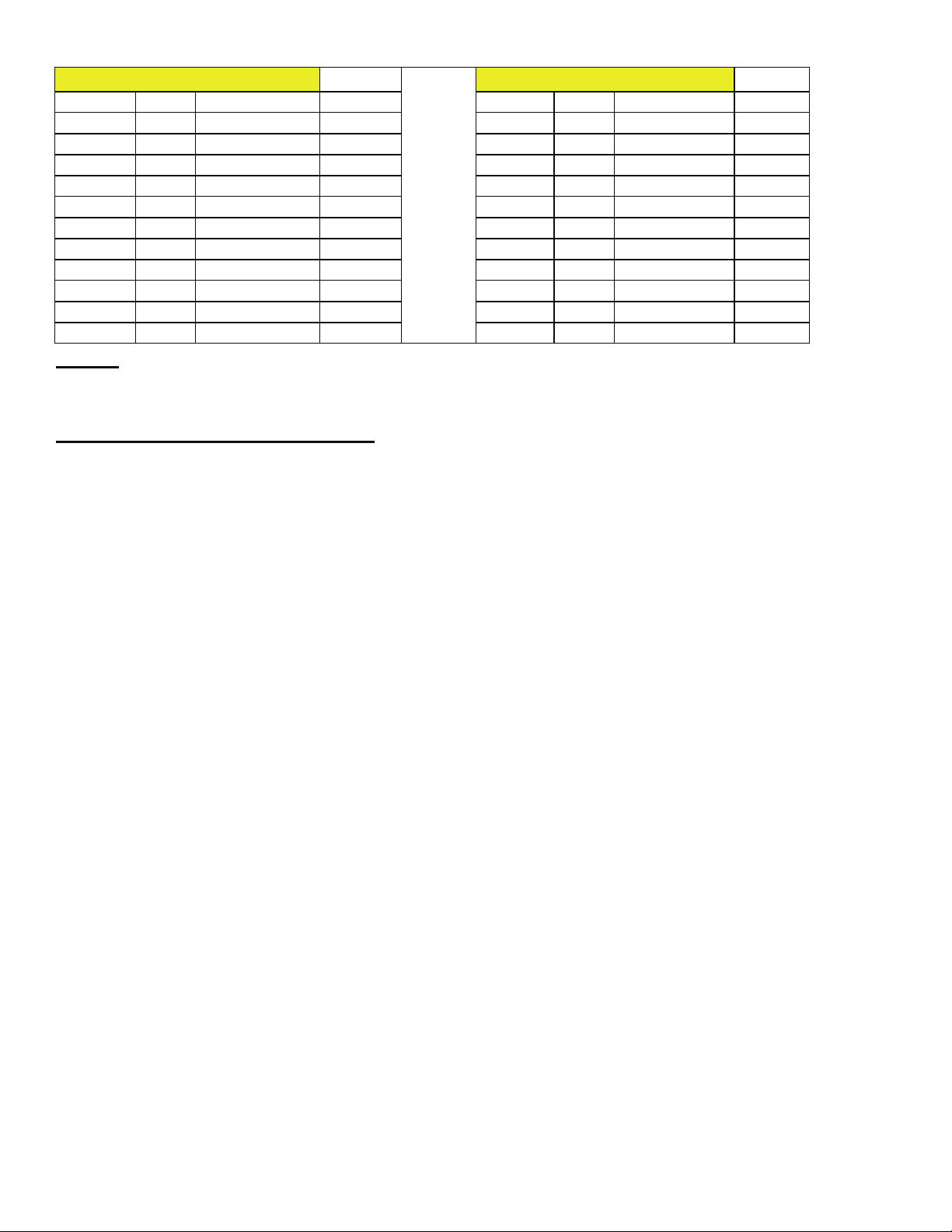
controller and settings. The variable speed control is bas ed on a percentage of spindle speed. The spindle is set at the factory to
approximatel y 3,000 RPM. Figure 3.6 shows the conversi on to surface fee t (and meters) per minute.
Fig. 3.2 –
Tracked Left
Fig. 3.3 –
Tracked Right
Your controller may have the following options depending on your models
installed options.
1. Forward – Stop – Reverse: This option allows your belt to run in a
Counter-Clockwise or Clockwise direction. Normal operation of the
machine is to run in a Forward or Clockwise direction. If you wish to run
your machine in a reverse or counter-clockwise direction please make sure
your machine is fitte d with part number 701-2, Anti-Rotate Bearing. If
you have a controlle r with the reverse switch installed you already have
the Anti-Rotate bearing. When reversing direction, make sure t he belt
comes to a compete stop. Then engage in the reverse direction.
2. Stop – Start: To start your m achine make sure the red mushroom switch
is pulled out and then move the toggle switch all the way to the start
position. The switch will return to the middle position. To turn the
machine off, lower the switch to the stop position.
3. Red Mushroom Stop Switch: This switch is inst alled incase of
emergency. Push the switch in to stop the grinder. To reset pull the switch
NOTE: Controller box and motor still will contain voltage even
when unit is in t he off position, and even if the mushroom push
stop is depres sed. Disconnect the unit from t he electrical
outlet for service work or whe n needed!
Fig. 3.4 –
Tracking Assembly
. Figure 3.5 shows your
Fig 3.5
Page 12
Model 960-272 6200 SFPM
Percent SFPM Spindle RPM SMPM Percent SFPM Spindle RPM SMPM
100.00% 6200
90.00% 5580
80.00% 4960
70.00% 4340
60.00% 3720
50.00% 3100
40.00% 2480
30.00% 1860
20.00% 1240
10.00% 620 437 188.976
0.00% 620 437 188.976
2962 1889.76
2665.8 1700.784
3312 1511.808
2898 1322.832
2484 1133.856
2070 944.88
1656 755.904
1242 566.928
592.4 377.952
Meters
Model 960-272 7000 SFPM
100.00% 7000
90.00% 6300
80.00% 5600
70.00% 4900
60.00% 4200
50.00% 3500
40.00% 2800
30.00% 2100
20.00% 1400
10.00% 700 437 213.36
0.00% 700 437 213.36
2962 2133.6
2665.8 1920.24
3312 1706.88
2898 1493.52
2484 1280.16
2070 1066.8
1656 853.44
1242 640.08
592.4 426.72
Meters
Fig 3.6
Maintenance of the model 960-272
• Every thirty days apply light mac hine oil to the rear wheel support to rear wheel handle interface. Two drops of oil i s sufficient.
• Every thirty days check the drive belt tension. If you can hear the belt “slap” the frame when the drive motor starts , the belt may
require re-tens ioning. Do this by loosening the two nuts that secure the motor to the belt guard and slide the guard forward. Do
not over tighten the belt. Doing so will s horten the life of the machine bearings. Tighten the two nuts.
• Routinely inspect the ma ch ine for loo s e h ar d w ar e . Tig h t en as required.
• Daily vac uum or otherwise remove dust and debri s buil d-up from the machine and the machine belt t r ac k.
There are no other mai ntenance actions requi red. All bearings are seal ed for life and require no additional lubrication.
Burr King Manufacturing can help you with problem soluti ons, and/or answers to your questions. Please call your Burr King
distributor first; if you can not reach satisfactory conclusi on please call the Burr King factory.
Page 13

MODEL 960-272
8" CONTACT WHEEL
PARTS LIST
BURR KING
1220 TAMARA LANE
WARSAW, MO. 65355
51
59
61
60
67
52
53
66
65
64
4
3
6
10
8
11
27
26 25
6
8
12
23
14
22 12
24
17
10
19
21
18
8
3
28
40
8
20
54
55 56
57
31
62
63
71
70
31
945K
72
31
68
68
74
69
32
75
32
1
2
5
7
13
9
15
31
16
11
29
33
31
30
32
31
33
31
34
36
37
35
39
36
37
38
41
42
43
44
45
46
47
49
48
50
Page 14
ITEM NO.
1 941
2
3 4
4 2
5 908
6 42
7
8 17
9
10 920
11
12 39
13 725
14 730
15
16 6
17 40
18
19
20
21 943
22 923
23
24
25 18
26 922
27 921
28
29 701
30
31 5
32 30
33 31
34 917
35
36
37
38
39
40
41 902
42 726
43 727
44 912
45
46 1431
47
48
49
50
PART NUMBER
MOTOR
5-0014
1-0003
900A
429K
920K
1-0004
4-0007
5-0035
2-0023
1-0019
916-1
966-01
5-0008
2-0046
903K
904BK
964-01
5-0032
907K
701B
701F
707c
960-272
DESCRIPTION
BASE
CALL FACTORY *
WASHER, 5/16 SAE ZINC PLTD
BOLT, 5/16-18x1 1/2 HEX HEAD
ADAPTER, C-FACE MOTOR
WASHER, SAE, 3/8
WASHER, LOCK 3/8, INTERNAL STAR
WASHER, 960-616, AN
BOLT 3/8-16 x 1 1/4 HEX HEAD
STUD 3/8"x1 1/2", DOUBLE
FRAME/GUARD ASSEMB
NUT, 3/8-24, JAM, ESNA, NTE
PULLEY, 2 1/2
PULLEY, 3
BELT, V DRIVE
SCREW 1/4-20 x 1 1/2 FH SOC
WASHER, SAE, 3/8
STUD 3/8"x1 1/2", DOUBLE
BOLT 3/8-16 x 1 1/4 HEX HEAD
NUT, 3/8-16, ELASTIC LOCK GD 2
BAR, EXTENSION
BRACKET, TRACKING
WASHER, #10, LOCK, HIGH COLLAR
SCREW, 10-24 X .625 ALLEN HEAD
WASHER, 960-516, AN
LOCK, KNOB, TRACKING
KNOB, TRACKING ASSY
BOLT, 5/16-18x1 1/2 HEX HEAD
HOUSING, BEARING, w/keyway
ARM, WORKREST SUPPORT
WASHER, 1/4 AN
SCREW 1/4-20x1 SHCS
SCREW 1/4-20x1 1/4 SHCS
WORKREST
REST EXTENDER
WASHER, 1/4, LOCK, EXTERNAL
SCREW, 1/4-28x1/2 BH, BLK OX
GUARD, CONTACT WHEEL
BRACKEN, PLATEN
PLATEN, MAIN 272
WHEEL, CONTACT
FLANGE, OUTER WHEEL
NUT, 5/8-18 RH, JAM, BRT PLT
GUARD, IDLER WHEEL
WASHER, 1/4, LOCK, SPLIT, PLTD
SCREW, 1/4-20 x 1/2 ALLEN HEAD
WHEEL, IDLER, w/Brg. & Shaft
BEARING
RING, RETAINING 5/8 EXT.
SHAFT, BEARING
QTY.
1
1
7
4
1
4
2
7
2
3
1
4
1
1
1
3
1
1
1
1
1
1
3
3
1
1
1
3
1
1
8
4
2
1
1
4
4
1
1
1
1
1
1
1
2
2
1
1
2
1
ITEM NO.
51 934
52 14
53 13
54 736
55 15
56 9
57
59
60 28
61 27
62
63
64
65
66 26
67
68 3
69 738
70 939
71 34
72 935
74 21
75 20
PART NUMBER
937G
737F
937C
737E
737D
737B-1
737A
* 011C
945K
DESCRIPTION
SUPPORT, REAR WHL, w/STUD
NUT, 10-24, KEP
SCREW, 10-24 x 3/4, SOC, HD, CAP
SECTOR
WASHER, 5/16 LOCK, SPLIT
SCREW, 10-24x1/2 BH, BLK OXIDE
HANDLE
PAWL
SCREW, DRIVE, #2 x 1/4
SCREW, DRIVE, #8 X 5/8
STRIP, HANDLE
NIPPLE, PIPE
SPRING, BUTTON
BUTTON
PIN, 3/32 x 3/8, ROLL PLTED
KNOB, REAR TENSION ARM
NUT, 1/4-20 JAM, PLTD
SPRING, BELT TENSION
GUIDE, SPRING
SCREW, 1/4-20 X 1, FH PHILLIPS
SUPPORT, REAR WHEEL
WASHER, 1/2 ID
NUT, NYLOK JAM, 1/2-20
NOTE
ROCKER SWITCH FOR 1PH
QTY.
1
1
1
1
2
2
1
1
1
1
1
1
1
1
1
1
2
1
1
1
1
1
1
BURR KING
1220 TAMARA LANE
WARSAW, MO. 65355
Page 15
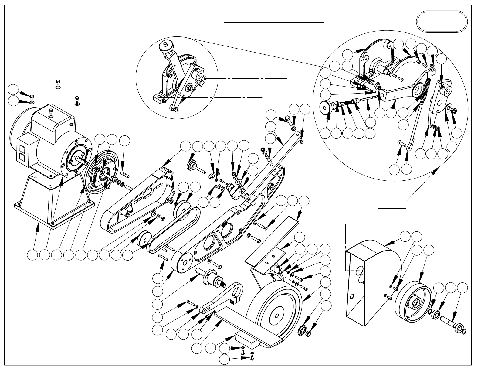
MODEL 960-272
10" CONTACT WHEEL
PARTS LIST
51
59
50
58
53
BURR KING
1220 TAMARA LANE
54
WARSAW, MO. 65355
55
66
72
4
3
20
19
21
6
8
10
2
1
5
9
7
8
6
13
15
12
11
14
27
24
26
25
23
12
8
18
17
10
8
3
28
42
41
52
57
56 67
31
65
64
63
62
60
61
69
31
68
70
31
72
71
66
945K
44
46
43
3736
3
47 45
16
11
29
33
31
30 32
31
35
34
36
37
32
38
39
40
49
48
50
Page 16

BURR KING
ITEM NO.
1 941
2
3 4
4 2
5 908
6
7
8
9
10
11
12 39
13
14
15
16
17 40
18
19
20
21
22
23
24
25 18
26
27
28
29
30
31
32 30
33 31
34
35
36
37
38 1002
39
40
41
42
PART NUMBER
MOTOR
42
5-0014
17
1-0003
920
900A
725
730
429K
6
920K
1-0004
4-0007
943
923
5-0035
2-0023
922
921
1-0019
701
948K
5
706-1M
966-01
5-0008
2-0046
726
727
913
964-01
960-272
DESCRIPTION
BASE
CALL FACTORY *
WASHER, 5/16 SAE ZINC PLTD
BOLT, 5/16-18x1 1/2 HEX HEAD
ADAPTER, C-FACE MOTOR
WASHER, SAE, 3/8
WASHER, LOCK 3/8, INTERNAL STAR
WASHER, 960-616, AN
BOLT 3/8-16 x 1 1/4 HEX HEAD
STUD 3/8"x1 1/2", DOUBLE
FRAME/GUARD ASSEMB
NUT, 3/8-24, JAM, ESNA, NTE
PULLEY, 2 1/2
PULLEY, 3
BELT, V DRIVE
SCREW 1/4-20 x 1 1/2 FH SOC
WASHER, SAE, 3/8
STUD 3/8"x1 1/2", DOUBLE
BOLT 3/8-16 x 1 1/4 HEX HEAD
NUT, 3/8-16, ELASTIC LOCK GD 2
BAR, EXTENSION
BRACKET, TRACKING
WASHER, #10, LOCK, HIGH COLLAR
SCREW, 10-24 X .625 ALLEN HEAD
WASHER, 960-516, AN
LOCK, KNOB, TRACKING
KNOB, TRACKING ASSY
BOLT, 5/16-18x1 1/2 HEX HEAD
BEARING, CONTACT WHEEL ASSY
ARM, WORKREST SUPPORT
WASHER, 1/4 AN
SCREW 1/4-20x1 SHCS
SCREW 1/4-20x1 1/4 SHCS
WORKREST
REST EXTENDER
WASHER, 1/4, LOCK, EXTERNAL
SCREW, 1/4-28x1/2 BH, BLK OX
WHEEL, CONTACT
FLANGE, OUTER WHEEL
NUT, 5/8-18 RH, JAM, BRT PLT
GUARD, 10" DRIVE WHEEL
PLATEN, MAIN 272
QTY.
1
1
9
4
1
4
2
7
2
3
1
4
1
1
1
3
1
1
1
1
1
1
3
3
1
1
1
3
1
1
5
3
1
1
1
4
4
1
1
1
1
1
ITEM NO.
43
44
45
46 1431
47
48
49
ITEM NO.
50
51 14
52 13
53
54 15
55
56
57
58 28
59 27
60
61
62
63
64 26
65
66
67
68
69 34
70
71 21
72 20
960-272
PART NUMBER
5-0032
912
707
701B
701F
707c
WASHER, 1/4, LOCK, SPLIT, PLTD
IDLER WHEEL 6 X 2, w/BRGS & SHAFT ALUM.
SCREW, 1/4-20 X 1/2 ALLEN HEAD
DESCRIPTION
GUARD, IDLER WHEEL
BEARING
WHEEL, IDLER CIR-CLIP
SHAFT, BEARING
945K
PART NUMBER
934
736
9
937G
737F
937C
737E
737D
737B-1
737A
3
738
939
935
SUPPORT, REAR WHL, w/STUD
SCREW, 10-24 x 3/4, SOC, HD, CAP
SCREW, 10-24x1/2 BH, BLK OXIDE
SCREW, 1/4-20 X 1, FH PHILLIPS
DESCRIPTION
NUT, 10-24, KEP
SECTOR
WASHER, 5/16 LOCK, SPLIT
HANDLE
PAWL
SCREW, DRIVE, #2 x 1/4
SCREW, DRIVE, #8 X 5/8
STRIP, HANDLE
NIPPLE, PIPE
SPRING, BUTTON
BUTTON
PIN, 3/32 x 3/8, ROLL PLTED
KNOB, REAR TENSION ARM
NUT, 1/4-20 JAM, PLTD
SPRING, BELT TENSION
GUIDE, SPRING
SUPPORT, REAR WHEEL
WASHER, 1/2 ID
NUT, NYLOK JAM, 1/2-20
NOTE
*011C ROCKER SWITCH 1PH
QTY.
4
1
1
2
2
2
1
QTY.
1
1
1
1
2
2
1
1
1
1
1
1
1
1
1
1
2
1
1
1
1
1
1
1220 TAMARA LANE
WARSAW, MO. 65355
Page 17
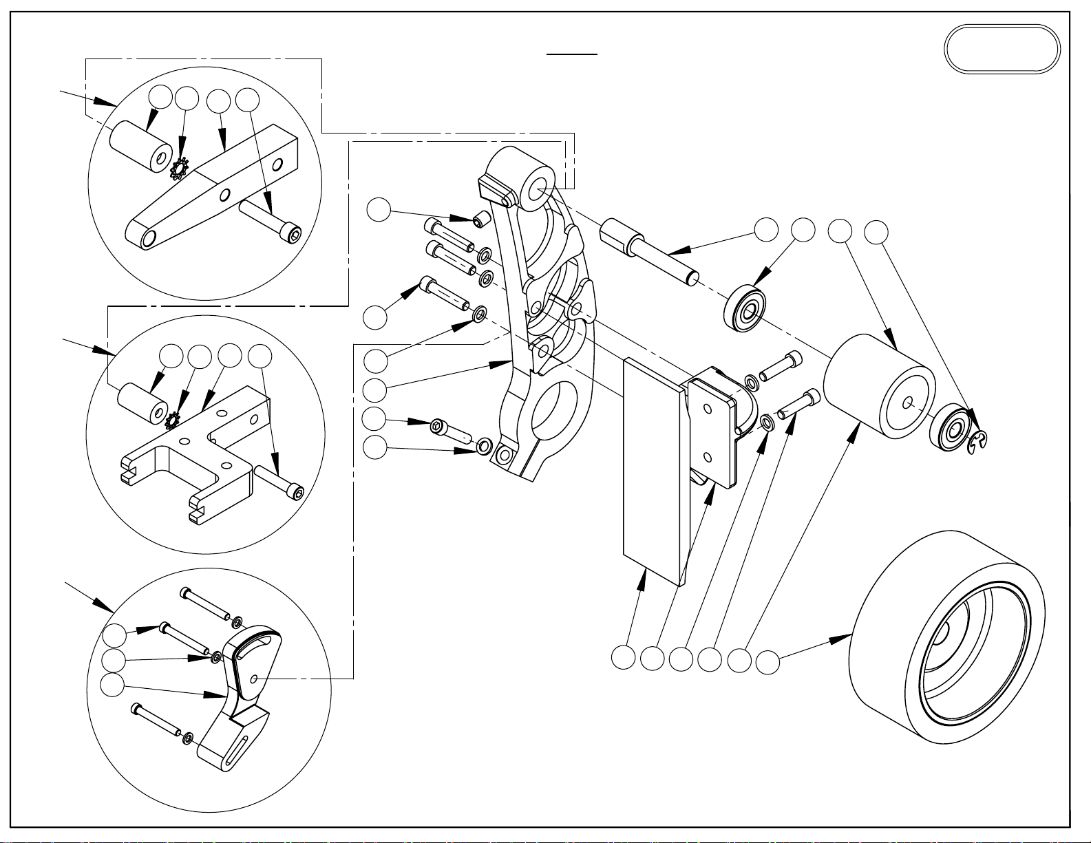
OPTIONAL ATTACHMENTS
1276
20
19
16
18
944
BURR KING
PARTS LIST
1220 TAMARA LANE
WARSAW, MO. 65355
2
8
9
10
11
4
1277
946K
13
15
14
20
19
17
18
3
1
4
3
6
5
3
7
10
12
Page 18
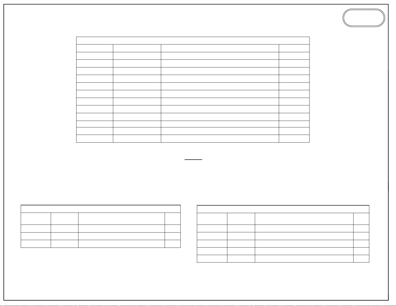
ITEM NO.
1 9066
2 25
3 5
4 31
5
6
7 30
8
9
10
11 1454
12 402
944
PART NUMBER
904B-5
904AKM
1444A
202B
202K
ARM, MAIN ATTACHMENT
SCREW, SET, 5/16-18 X 3/8, ALLEN
SCREW 1/4-20x1 1/4 SHCS
WHEEL, CONTACT 2x2 w/Brg. & Shaft
RING, RETAINING, E STYLE
DESCRIPTION
WASHER, 1/4 AN
BRACKET, PLATEN
PLATEN
SCREW 1/4-20x1 SHCS
SHAFT, IDLER
BEARING
CONTACT WHL, 5x2
NOTE
TO USE 944 MUST HAVE 907K IDLER WHEEL.
QTY.
1
1
6
4
1
1
2
1
2
1
1
1
BURR KING
1220 TAMARA LANE
WARSAW, MO. 65355
ITEM NO.
13
14 5
15
OPTIONAL ATTACHMENTS
946K
PART
NUMBER
946KM
2-0062
SCREW, 1/4-20 X 1.5 ALLEN
USE TO ATTACH WORKREST TO 944
DESCRIPTION
ARM
WASHER, 1/4 AN
QTY.
1
3
3
ITEM NO.
16
17
18 31
19
20
PART
NUMBER
1276B
1277B
5-0008
1277A
1276 & 1277
DESCRIPTION
ARM, UNI 1x1
ARM, FORK 1x2
SCREW1/4-20x1 1/4 SHCS
WASHER, 1/4, LOCK, EXTERNAL
STUD
QTY.
1
1
2
2
2
Page 19
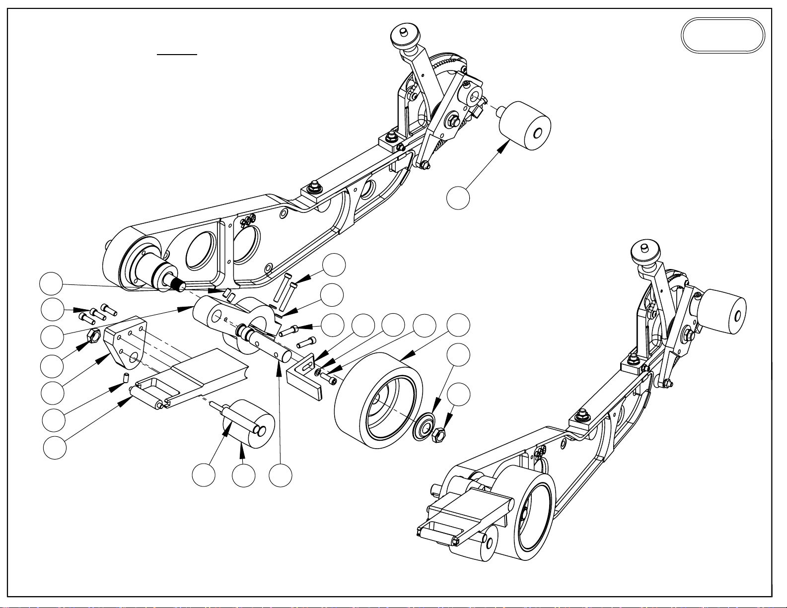
19
965
BURR KING
1220 TAMARA LANE
PARTS LIST
15
3
2
7
9
1
6
5
7
16
WARSAW, MO. 65355
18
12
11
17
14
4
13
15
8
Page 20
ITEM NO.
1 1425
2 5
3
4 1441
5 9653
6
7 209
8 1426
9 30
10 9654
11
12 9651
13 9652
14 727
15
16 402
17 726
18
19 1445
PART NUMBER
2-0011
5-0032
*AR2311
1444V
4-0015
965
DESCRIPTION
BRACKET, MOUNTING
WASHER, 1/4 AN
SCREW, 1/4-20 X 1.5 ALLEN
SCREW, SET, 1/4-20-1/2, ALLEN
GUARD, L, SMALL, WHL.
WASHER, 1/4, LOCK, SPLIT, PLTD
SCREW, 1/4-20 X 3/4 ALLEN HEAD
BAR, PIVOT
1/4-20x1 SHCS
SUPPORT, ARM, SMALL, WHL.
CONTACT WHEEL, 1x2, FORK, 70D SM
SUPPORT, WHEEL, SM
GUARD, PINCH, SMALL, WHL.
NUT, 5/8-18 RH, JAM, BRT PLT
WHEEL, IDLER
CONTACT WHL, 2X5
WASHER, SPRING FLANGE
NUT, 5/8-18 HEX, THIN, NYLON INSERT
SCREW, 1/4-20x 3/8, SET
QTY.
1
2
2
1
1
1
4
1
2
1
1
1
1
1
2
1
1
1
2
BURR KING
1220 TAMARA LANE
WARSAW, MO. 65355
* CALL FACTORY FOR OPTIONAL WHEEL SIZES.
Page 21
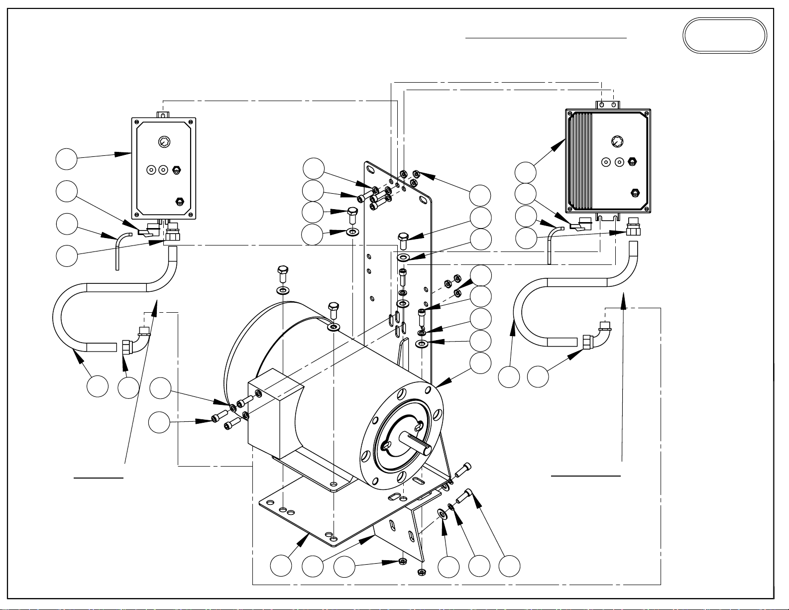
272 VARI SPEED
PARTS LIST
BURR KING
1220 TAMARA LANE
WARSAW, MO. 65355
12
15
10
13
11
14
6
5
9
4
6
5
7
9
4
7
5
6
4
8
11
16
15
10
13
14
1 HP
1.5 HP
1
2
7
4
3
5
Page 22
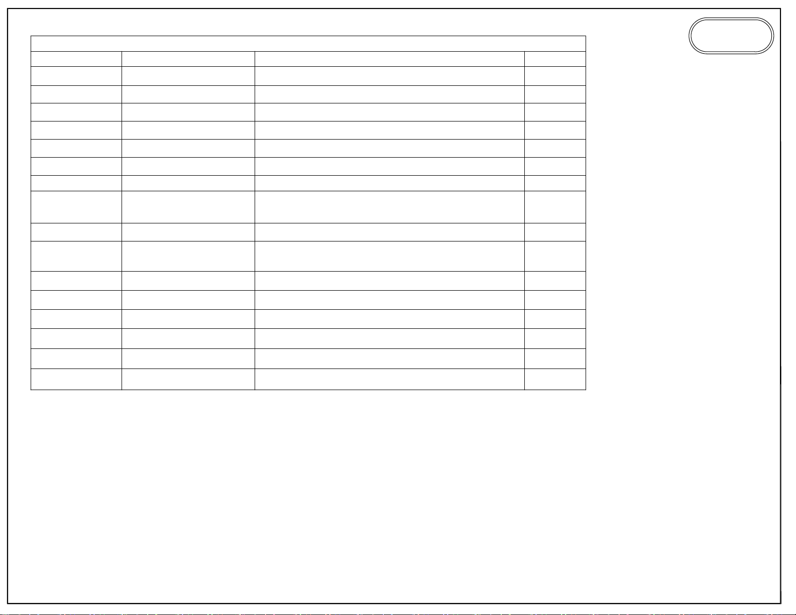
ITEM NO.
1
PART NUMBER
MB-4C
272 VARI SPEED
DESCRIPTION
BRACKET, MOUNTING, STARTER
QTY.
1
BURR KING
1220 TAMARA LANE
WARSAW, MO. 65355
2
3
941-3
5-0032
4 4
5 209
6 5
7
8
4-0013
100B-1725C
150B-1725C
9 37
10
015-1
017
11 020
12
864-1
13 775
14 776
15 643
16
862-3
BRACE, MB4 SUPPORT
WASHER, 1/4, LOCK, SPLIT, PLTD
WASHER, 5/16 SAE ZINC PLTD
SCREW, 1/4-20 X 3/4 ALLEN HEAD
WASHER, 1/4 AN
NUT, KEP, 1/4-20
1 HP MOTOR
1.5 HP MOTOR
BOLT, 5/16-18x3/4 HEX HEAD
120V CORD
220V CORD
CONDUIT 3/8" LIQUIDTIGHT
CONTROLLER, 115/220V/1PH INPUT
CONNECTOR, 3/8" STR, LIQ. TIGHT
CONNECTOR, 3/8", 90 DEG, LIQ. TIGHT
RELIEF, STRAIN 3/8" 90 DEG
CONT. 220/120V/1PH IN, 3PH OUT
1
2
8
10
8
8
1
4
1
1
1
1
1
1
1
Page 23
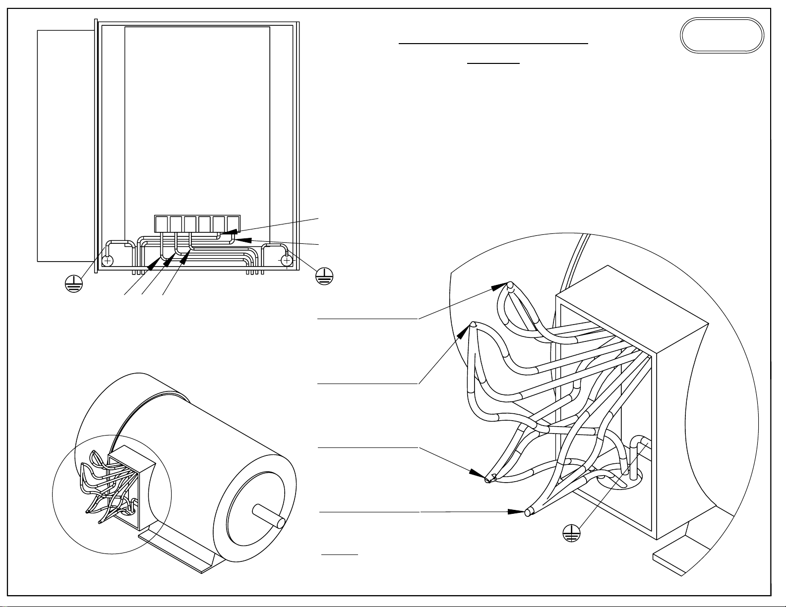
WIRING DIAGRAM
BURR KING
1220 TAMARA LANE
WARSAW, MO. 65355
U
V
W
U
V
W
A
L1
L2
BLUE
BROWN
TWIST TOGETHER
T4, T5, T6
TWIST TOGETHER
U, T7, T1
TWIST TOGETHER
V, T2, T8
TWIST TOGETHER
W, T3, T9
NOTE:
LEESON- ALPH. & NUM.
BALDOR- NUM.
DETAIL A
SCALE 2 : 2.5
 Loading...