

Page 1

BURR KING MFG. CO., INC
1220 Tamara Lane
Warsaw, MO 65355
www.burrking.com
(660)438-8998 • 800-621-2748
Fax (660)438-8991
MODEL 600 & MODEL 800
I
NSTRUCTION MANUAL
Model 60100 Shown
BURR KING MODEL 600/800
DEBURRING & POLISHING MACHINES
Page 2

BURR KING MFG. CO., INC.
1220 TAMARA LANE
www.burrking.com
WARSAW, MO 65355
(660)438
-
8998
s
(800) 621
-
2748
FAX (660) 438
-
8991
June, 2007
Burr King Manufacturing Company. Inc. warrants the below product to be free in material and workmanship. The period of warranty is 1 year
(90 days for vibratory bowls of 20 quart and lesser volume) from the date of purchase. No warranty is provided for products that have been
modified, abused, handled carelessly, where repairs have been made or attempted by others, or for freight damage. No warranty is provided for three
phase electric motors, controllers, etc. when the motors, controllers are not protected by magnetic starters that were supplied and installed by Burr
King Manufacturing Company. Inc. No other warranty, written or verbal is authorized by Burr King Manufacturing Company, Inc.
During the warranty period Burr King Manufacturing Company, Inc (or its authorized suppliers or agents) will replace or repair the below
product without charge if the product is found by Burr King Manufacturing Company, Inc. to be defective. To receive warranty services you must
contact Burr King Manufacturing Company, Inc. and receive authorization fir warranty service. Unless otherwise authorized by Burr King
Manufacturing Company, Inc. Products (see * below) must be returned to the factory to receive warranty service.
*Motors, speed controllers, and certain other accessories are warranted by their respective manufactures. To receive warranty service on these
items you must contact a brand label service center that supports the product in need of service. Burr King Manufacturing Company; Inc. will assist
you in locating a service center.
For the first thirty days after purchase, and when Burr King Manufacturing Company, Inc. authorizes warranty service, we will pay normal and
necessary surface freight charges both ways (except for items in *). After thirty days the customer is responsible for all freight charges. Where
possible Burr King Manufacturing Company, Inc. may elect to make on site service and/or repairs necessary to return the product to serviceable
condition.
To assure prompt warranty service it is necessary that you complete and return the below warranty information to Burr King Manufacturing
Company, Inc. please FAX or MAIL at your convenience.
Product model: _______________________ Serial number: _______________________
Date Purchased: ______________________ Purchased from: ______________________
Address: ____________________________ City: _______________________State/Prov: _________Postal code________
Your company name: _____________________________________________
Address: _____________________________City: _______________________State/Prov: __________Postal code________
Phone: _______________________________Fax: _______________________Email: _______________________________
Your name: ___________________________Title: _______________________
How did you learn about Burr King products?
Trade show___Web___Industrial Distributor ___Advertisement ___Other __________________________Which one:________________________
What is the intended use of this product? ______________________________________________________________________________________
Please indicate the general work types performed at your company, check all that apply:
Fabrication___Machining___Casting__Molding___Welding___Finishing___Assembly___Research___Other___
Please indicate the primary product focus of your company; check all that apply,
Aircraft/Missile___Automotive___Contract machine___Contract Fabrication___ Agricultural____Maintenance___ Recreational___
Job shop___Foundry___Construction___Arts___Orthopedic___Dental___Medical___Other_________________________________
Please tell us what we can do to improve our products:
________________________________________________________________________________________________________________________
________________________________________________________________________________________________________________________
May we contact you? Yes___No___
Thank you for purchasing Burr King products!
Page 3

BURR KING MFG. CO., INC.
1220 TAMARA LANE
(660) 438
-
8998
s
(800) 621
-
2748
FAX (660) 438
-
8991
WARSAW MO 65355
WWW.BURRKING.COM
June 21, 2007
LETTER OF AUTHENTICITY
This letter is to certify that all Burr King Belt grinders, Disc
grinders, Polishing machines Vibra King Chambers and Bowls are
manufactured and assembled in the United States of America.
(Tariff number 847990 criterion A)
Don Mac Carthy
President
See our catalog at www.burrking.com contact us at [email protected]
Page 4

BURR K ING MFG. CO., INC.
1220 TAMARA L ANE
WARSAW MO 65355
WWW.BURRKING.CO
(660) 438-8998
FAX (660) 438-8991
(800) 621-2748
s
February 2005
OPERATOR, and OPERATING AREA SAFETY
Subject equipment includes Grinders, buffers, polishers, and other rotating equipment. Serious injury
or death may occur if minimum safety precautions are not understood, and obeyed by operators and
those other persons who may be in the immediate vicinity of the subject equipment. Persons who
operate, or are in the immediate vicinity of the subject equipment must be properly trained in, and
use, minimum safety precautions and procedures for such machinery.
Minimum safety requirements to operate, or work in the immediate vicinity subject equipment:
1. Read and understand all operating instructions, manuals, labels, and other information provided with the
equipment.
2. Install the equipment according to manufacturer’s instructions.
3. Securely bolt the equipment to a rigid, structurally sound mounting surface.
4. Use and wear proper eye and face protection.
5. Use and wear proper protection for the body, hands, fingers, feet, and legs.
6. Review and understand all machine guards, adjustments, and points of exposure to potential injury.
7. Do not remove, tamper with, or otherwise alter, equipment guards, and other safety features.
8. Insure the machine is adjusted, and remains adjusted according to manufacture’s requirements.
9. Maintain the equipment in good operating condition.
10. Have another person who is knowledgeable in proper and safe operation of the subject equipment
demonstrate proper and safe operation to all operators, and to those persons who might be in the immediate
vicinity of the subject equipment.
11. Use work piece holding devices when ever possible that diminish the possibility that persons will come
in contact with moving machine pieces, or spark/debris output from the machine.
12. Use spark and debris arresting apparatus. Such apparatus should be connected to the machine so as to
contain dust and debris that is generated, and to suppress sparks thereby limiting human inhalation risk, and
the risk of fire or explosion.
13. Use appropriate inhalation apparatus to protect person from ingestion and/or inhalation of sparks, debris,
smoke, particulates, etc.
14. Avoid mixing different metals, alloys, and materials. To mix such materials might create a fire or
explosion hazard.
15. Protect persons from work pieces, particulates, etc. that could be forcibly ejected from the machine. For
example, a buffing wheel or grinding belt can “grab” a work piece while the work piece is being buffed,
polished, ground, or otherwise conditioned, resulting in forcible ejection toward the operator or those in the
vicinity of the machine. The use of leather aprons, gloves, and eye shields are examples of protective gear
that may be effective. In general do not grind, buff, or otherwise engage the traveling belt, wheel, or disc
surface with the work piece pointing into the direction from which the belt, wheel, or disc is traveling.
However, if you choose to do so be aware the work piece may lodge in the traveling belt, wheel, or disc and
be forcibly, and dangerously ejected.
16. Do not operate this machine if the gap (nip point) between a moving belt, wheel or disc and the work
support surface exceeds 1/8 inch.
17. Do not operate this machine if the gap between the moving abrasive belt, disc or wheel and the adjacent
face
page 1 continued on next page
See our catalog at www.burrking.com Contact us at [email protected]
Page 5

Continued from page 1
of the work rest (or table) will permit passage of the work piece through the gap (nip point). Note, however,
that certain alloys such as titanium may create conditions where grinding debris can accumulate in a tight gap
creating a potential fire hazard. When in doubt consult with your safety officer. Failure to observe this
warning may result in the work piece or other item being caught in this gap, and/or being forcibly ejected.
Failure to heed this warning may cause serious bodily harm to the operator and/or bystanders. NEVER USE
THIS EQUIPMENT IF YOU ARE NOT PROPERLY TRAINED IN ITS OPERATION and/or SAFE
USE! IF IN DOUBT STOP and ASK FOR GUIDANCE!
18. Never position the work rest table at an acute angle between the top of the work rest table and the moving
belt or wheel. Doing so will create “nip point” that can cause serious injury should an operator body part
become entangled (pulled into) the nip point created by this acute angle.
19. Do not operate the equipment, or allow others to operate the equipment without proper training in these
and other rotating machinery safety requirements.
20. Do not perform maintenance on the equipment unless you are fully qualified to do so, and understand all
necessary safety and operating requirements.
21. Do not leave the machine unattended while it is running.
22. Correct equipment or safety problems immediately. Do not operate the equipment when it requires
maintenance, or correction.
23. Install and use high quality abrasive belts, wheels, discs, media, etc., as appropriate to your machine.
Understand and follow the operating requirements provided by the manufacturer of these materials.
Rotational Speed Warning, Contact Wheels
Scope: Contact wheels manufactured by Burr King Manufacturing Company, Inc., which have rubber or
urethane tires. Examples include but are not limited to stock codes 202, 302, 402, 502,702, 802, 902, 1002,
1202 and variants. Variants have stock codes that begin with the base number; i.e. 802-S-55 is an 802
variant.
Users are warned not to exceed the below listed revolutions per minute (RPM) on the subject wheels. Failure
to heed this warning may lead to tire de-bonding, fragmentation, or other mechanical failure. Such failures
may cause serious personal injury to operators or bystanders, and/or cause property damage. All Burr King
products are warranted for various time periods to be free of material and/or workmanship defects. Burr King
Manufacturing Companies standard warranty policy is summarized as follows for contact wheels. 1 year
from date of purchase if mounted on a Burr King machine purchased on the same date or 90 days if
purchased as a spare or replacement part. Our warranty does not apply to wheels that are mounted on
products not manufactured by Burr King Manufacturing Company, Inc. Users who mount Burr King
manufactured contact wheels on product not manufactured by Burr King Manufacturing Company, Inc. do so
at their own risk and assume all liability for having so mounted the contact wheel(s).
Remember good safety practice demands guarding to protect operators and bystanders from wheel failure
and/or debris. Never use the subject contact wheels without proper guarding that meets commonly accepted
safe practice. See OSHA, U/L, CSA, CE, ISO and other respected safety standards.
Stock code
Contact Wheel Maximum Safe RPM
202, 302 10000
402, 502, 702 802 4400
902, 1002 2200
1202 1600
Page 2, continued on page 3
See our catalog at www.burrking.com Contact us at [email protected]
Page 6

Continued from page 2
Occupational Noise Exposure
Burr King products produce levels of noise consistent with their intended purposes. The level and spectral
content of noise produced is dependent on the product type, the degree that the product is maintained in
proper operating condition, the abrasive/media and accessories used, the specific application, and the
surrounding environment. Noise levels produced by various Burr King grinders and polishers, as measured at
the Burr King factory, range from 80 to 93 decibels. Product operators and persons in the immediate product
vicinity should be protected from excessive noise does levels as prescribed in OSHA regulation 29, piece
1910.95 titled “Occupational Noise Exposure”.
ROTATING EQUIPMENT CAN BE DANGEROUS TO OPERATORS AND THOSE WHO MAY BE
IN ITS IMMEDIATE OPERATING VICINITY. IT IS THE ABSOLUTE AND DIRECT
RESPONSIBILITY OF PURCHASERS, MANAGERS, AND OPERATORS OF THIS EQUIPMENT
TO UNDERSTAND AND OBEY THE FOREGOING MINIMUM OPERATING SAFETY
REQUIREMENTS. IF YOU HAVE QUESTIONS OR SAFETY CONCERNS REGARDING
OPERATING THE SUBJECT EQUIPMENT PLEASE CALL YOUR AUTHORIZED BURR KING
DISTRIBUTOR, OR BURR KING MANUFACTURING AT 1-800-621-2748. YOUR SAFETY IS
OUR FOREMOST CONCERN!
Burr King Manufacturing disclaims any and all responsibility for injuries, damage, loss of income, or other
adverse consequence as might be incurred by purchasers, managers, and operators of this equipment.
Page 3 is last page
See our catalog at www.burrking.com Contact us at [email protected]
Page 7

BURR KING MFG. CO., INC.
1220 TAMARA LANE
WARSAW, MO 65355
WWW.BURRKING.COM
(660) 438-8998
FAX (660) 438-8991
(800) 621-2748
Technical tip May 16, 2006
As you may know we improved many of our 120 and 220-volt
buffers to use a three-phase AC motor with an inverter controller rather than the DC motors and a rectifier
controller previously used. This change is transparent to the end user since the machine is “plugged in” to
single-phase outlets. The use of a three-phase motor permits the use of computerized “inverter” controls to
achieve variable speed control. Current technology does not support the use of single-phase motors for
variable speed operation except through the use of mechanical systems. We made this change for the
following reasons:
• Customers fr
equently demand excess horsepower output from the machines. Regardless of the “labeled”
horsepower electric motors can deliver power well in excess to stated capability for short periods of
time. Since there is “no free lunch” this excess horsepower is sustained by high current drain on the
supply service (what comes out of the wall). Further this high current drain taxes the control module on
the grinder or buffer and all interconnect circuitry such as the electrical cord which can get warm as
evidence of the overstress. The new configurations are more tolerant of excess horsepower demand.
• The DC
motors and controllers previously used had fuses that would “blow” when the customer
demanded even short periods of overload necessitating the customer searching for and replacing up to
two fuses at the machine and perhaps having to reset an wall circuit breaker. The new configurations
are more tolerant of overload, but in the event of an overload the customer needs only to reset the
controller.
• The DC
motors require the use of “brushes” that have a specified service life of about 1200 hours with
normal loading. Excess loading greatly reduces this time. The three-phase motors used with the new
configurations do not have brushes and are inherently more reliable.
• The DC
controllers previously used are very limited in their ability to be interfaced with external
controls as might be found with robotics or other automation devices. The new AC controllers have
greatly expanded interface capability.
• The DC
motors and controls were often limited in their ability to drive the machines to maximum
specified belt or wheel speed. The new configurations can be readily set for optimum advertised
speeds.
• The cost of
modern inverter controls is now competitive with the cost of the older DC control modules;
and three-phase motors are very competitive with DC motors. This allows us to deliver a superior
value to our customers and to expand the application utility of our products without negatively
impacting the price that our customers pay.
Because of the common and widely used 120 volt single-phase service (y
there are some important application aspects that you and our customers need to bear in mind. These apply
to the new variable speed configurations or for that matter any electrical motor driven machine where the
horsepower is 1-½ or greater. People often do not understand the electrical supply beyond “it comes out of
the wall” and “if it is my garage it must work on everything specified 120 volts, single phase”. Many homes,
offices, and even factories (in accordance with local and national codes) are wired with 14-guage feeder
wire to the 120-volt outlets making the supplied service inadequate for machines with 1-½ horsepower
single-phase variable speed grinders and
our home, office, and in factories)
1
Page 8

motors. To force these inadequate services to deliver power that is greater than their designed 15-ampere
capability leads to early equipment failure and potential fire danger. This must always be considered when
choosing the electrical supply.
• Burr
King provides 1-½ horsepower, 120-volt machines with a 20-ampere power cables and
connectors. This is necessary to assure that the power cord does not dissipate excess energy (delivers all
available current to the motor), and to assure that the user plugs into a supply capable of delivering the
required 20 amperes of current. You can identify the 20-ampere cable by its 20-ampere plug that has a
90-degree orientation of the two flat blades. If a user defeats this performance and safety feature he
does so at his own hazard.
• At the application site y
ou and our customer must assure 20-ampere service is used. Should the user
defeat the 20 ampere polarized plug provided by Burr King in favor of a 15-ampere service he may
experience nuisance circuit breaker trips.
• A 120 -volt,
single phase 1-½ horsepower machine must always be connected to at least a 20ampere 120-volt source that incorporates 12-gauge wire at minimum. 20-ampere circuit breakers
must never be used with smaller than 12-gauge wire. Failure to observe this warning may create a
fire hazard and result in the loss of life and or property.
• It is common (b
y code and fact) to have five or more AC outlets wired to a single 20-ampere circuit box
breaker. This means that when a 20-ampere demanding device (1-½ horsepower motor) is connected to
one of the outlets no other device should be connected to the other shared outlets, in other words all of
the available current must be reserved for the 1-½ horsepower motor.
• 220-volt, single-phase 1-½ horsepower configura
tions should be connected to 15-ampere service.
Burr King machines are provided with appropriate power cables and connectors for this service
arrangement. Similar concerns exist for 220-volt, single-phase systems; however, 120-volt systems
are far and away of more concern and therefore require greater awareness and pro action.
• For 1-½ hors
epower, 120-volt, single phase motor applications the use of extension cords should be
avoided. If it is necessary for an extension cord to be used assure that the cord does not exceed twenty
feet in length and is constructed with 12-gauge or larger wire. Failure to observe this will lead to
reduced performance, premature failure, and a potential fire hazard.
Remember that this is an important issue that effects product performance, reliability, and physical
safety. If you have doubts or need assistance call the factory. The new configuration machines will safely
deliver solid performance for many years provided they are supplied with and adequate AC power.
Finally, we think that you will agree the new configuration vari
able speed machines are a superior value
because of their improved reliability, improved tolerance to overloads, and extended capability!
2
Page 9

BURR KING MFG. CO., INC.
1220 TAMARA LANE
WARSAW MO 65355
WWW.BURRKING.COM
(660) 438-8998 (800) 621-2748
FAX (660) 438-8991
June 1999
Operating instructions for the Model 600/800 buffer
The model 600/800 buffer is a single spindle buffer designed to use cotton, nylon, flap, wire, and other buffing and/or deburring wheels.
and operator safety use wheels manufactured by well respected manufacturers.
* Use wheels that are the proper size and type for y
to 2 inches wide. Different wheels require properly configured adapters (i.e. WA-N, WA-1-1/2, WA-1, WA-2, WA 11/4).
* Do not use wheels that are old and/or excessively worn.
• Do not operate the buffing wheel in a reverse rotation. The spindle must rotate CCW when viewed from the right side
(opposite of the motor).
• Do not exceed the m
model 600/800 spindle speed, which ever is less.
Prior to operating the model 600/800 please take time to do the following:
1. Insure that you have received all of the items that you ordered. Com
of course with the physical items received.
2. Verify that there is no obvious shipping damage. If shipping dam
intention to file a freight damage claim. They will assist you.
3. Verify that the AC power that is identified on the machine as received m
the machine with. Do not modify the machines wiring without first contacting your distributor or Burr King
manufacturing.
4. Do not modify or defeat any AC wiring safety feature. In example, do not remove the grounding pin on the AC plug.
5. Verify that you have received a warranty card, parts lists, catalog, and Operator, and Operating Area Safety
Instructions.
6. Complete the warranty card and return it to Burr King Manufacturing.
7. Verify that the buffing wheel guard (P/N 703) is in place and functional.
8. Prior to operating the model 600 read the Operator, and Operating Area Safety Instructions
persons who will operate the model 600/800, or who will work in the vicinity of the model 600/800 read, understand, and
comply with these instructions.
9. Insure that the model 600/800 is located in an area that provides clear access to the m
clear and unobstructed access to the machine. The work place should be free from floor obstructions, trip points, and other
faults that may reduce operator safety.
10. Burr King recommends that all three phase installations include a magnetic starter. Magnetic starters protect motors
from “single phasing”, overheating, etc. thereby reducing the risk of damage to the equipment and/or fire hazard to your
facility.
11. Insure that the model 600/800 AC power source is properly sized, and properly fused. You should consult a competent
electrician, or y
Functional operating instructions for the model 600/800 buffer
The model 600/800 was fully tested and verified to comply with requirements prior to shipping from the factory. No
adjustm
1. With the m
2. Insure the buffing wheel is firm
wheel adapter suitable to the 5/8-inch arbor and the wheel desired for use is used to secure and tighten the wheel to the
ents should be necessary. You should perform the following steps:
Stone or vitreous grinding wheels must not be used on the model 600/800
our machine. The model 600 uses 6 inch diameter wheels up
aximum recommended buffing wheel speed (see the manufacture’s instructions), or 4200 RPM
pare the packing slip with your purchase order, and
age is discovered notify the freight carrier of your
atches the AC power that you intend to operate
ou may call Burr King Manufacturing for guidance.
achine securely bolted to its table, pedestal, and/or floor point connect the AC power to its source.
ly tightened to the spindle. A WA-N, WA-1/2 , WA-1, WA-2, WA-1-1/4, or other
. For maximum effectiveness,
carefully. Insure that all
achine such that operators have
See us at www.burrking.com Contact us at info at burrking.com DOC 600/800op-99
1
Page 10

model 600/800 spindle. A buffing wheel running in reverse rotation can unscrew from the spindle, creating a serious
personnel safety hazard.
3. Engage the motor by placing the ON/OFF switch to ON. The wheel should rotate smoothly
the front face of the buffing wheel moving toward the floor. If either of these conditions are not met turn the machine OFF
immediately.
b. If the model 600/800 runs in reverse ( up from the floor) you must correct this by changing the main
drive m
COMPETENT ELECTRICIAN SHOULD PERFORM ALL ELECTRICAL WORK ON THE MODEL 600/800.
1) Reverse the motor direction of a three phase motor by reversing any two legs of the
input power lines.
2) Reverse the motor direction of a single phase motor by reversing leads 5 and 8 found within the m
located on the motor, or as otherwise instructed on the actual motor label.
c. If the model 600/800 has excessive vibration turn the m
assistance.
Maintenance for the model 600/800
FIRST DISCONNECT THE MACHINE FROM ITS AC POWER SOURCE.
* Every thirty days check the v-belt (P/N 429) tension. If you can hear the belt “slap” the v-belt guard (P/N 428) when the
drive m
the machine base (P/N 731) and slide the motor toward the rear of the machine. Tighten the four bolts.
* Daily vacuum or otherwise remove dust and debris build-up from the machine and the machine belt track.
There are no other maintenance actions required. All bearings are sealed for life and require no additional lubrication.
------------------------------------------------------------------------------------------------------------
Remember for operator safety and the continued effectiveness of your model 600/800:
Do not defeat the safety guards and other safety provisions of the model 600/800.
Do not reach inside the safety guards while the machine is running. To do so is haz
Do not use fluids in your buffing process unless your model 600/800 is designed for liquid operation (NEMA 4, 4X).
To do so may create an electrical safety haz
Do not use your model 600/800 to grind/polish explosive materials such unless it is equipped with explosion proof
electrical devices and motor.
Do not mix alloys in your buffing. To do so may create an explosion hazard.
Do not use stone or vitreous wheels on the model 600/800. To do so will create an operator safety haz
Do use eye, hand, face, arm, leg, feet and body protection that is adequate to protect against flying debris, forcibly
ejected work pieces, broken abrasive belts, etc.
Do train operators and others in safe operating practices.
Post these or equivalent instructions such they are available for ready operator reference.
otor rotation direction. FIRST DISCONNECT THE MACHINE FROM ITS AC POWER SOURCE. A
achine OFF and call the Burr King factory for
otor starts, the v-belt requires re-tensioning. Do this by loosening the four bolts (P/N 2) that secure the motor to
ard.
in a CCW direction with
etal wiring box
ardous.
ard.
Burr King Manufacturing can help you with problem solutions, and/or answers to your questions. Please call your Burr King
distributor first. If you can not reach satisfactory conclusion please call the Burr King factory, telephone 1-660-438-8998 or 800-621-
2748.
See us at www.burrking.com Contact us at info at burrking.com DOC 600/800op-99
2
Page 11
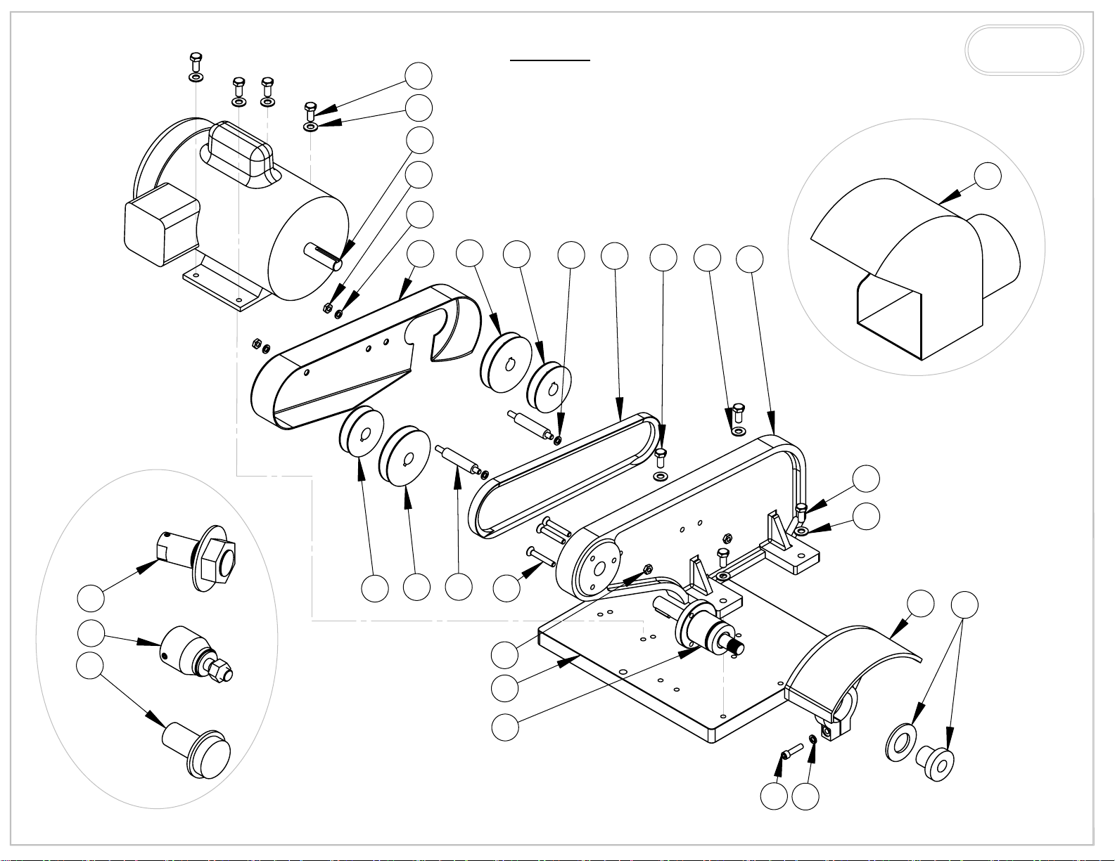
17
M600
SCHEMATIC
3
BURR KING
1220 TAMARA LANE
WARSAW, MO. 65355
OPTIONAL
18
12
16
OPTIONAL
19
8
14
15
8
13
4
3
2
4
3
20
21
22
15
14
11
12
5
7
11
1
6
9
8
Page 12
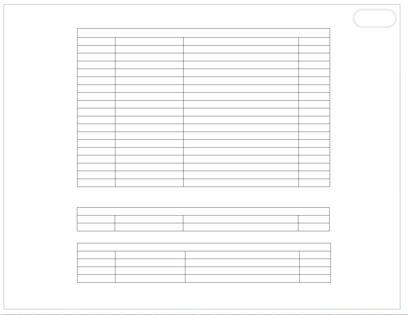
ITEM NO.
1 731
2 600
3 4
4 1
5 6
6 701
7 903
8 5
9 31
10
11
12 3
13 729
14 730
15 725
16 728
17 2
18
PART NUMBER
WA1
728A
MOTOR*
M600
DESCRIPTION
BASE, MACHINE
FRAME, MAIN
WASHER, 5/16 SAE ZINC PLTD
BOLT, 5/16-18x1 HEX HEAD
1/4-20 x 1 1/2 FH SOC
BEARING, CONTACT WHEEL ASSY
GUARD, CONTACT WHEEL
WASHER, 1/4 AN
SCREW 1/4-20x1 1/4 SHCS
ADAPTER 1"
STUD, GUARD, V, BELT
NUT, 1/4-20 JAM, PLTD
BELT, V DRIVE
PULLEY, 3.0
PULLEY, 2.5
GUARD, V-BELT
BOLT, 5/16-18x1 1/2 HEX HEAD
CALL FACTORY FOR MOTOR
QTY.
1
1
8
4
3
1
1
5
1
1
2
4
1
2
2
1
4
1
BURR KING
1220 TAMARA LANE
WARSAW, MO. 65355
ITEM NO.
19
ITEM NO.
20
21
22
PART NUMBER
DS6
PART NUMBER
WA14
WA12
WA2
* 011C ROCKER SWITCH FOR 1PH
OPTIONAL ATTACHMENT
DESCRIPTION
SCOOP, DUST
ACCESSORY WHEEL ADAPTERS
DESCRIPTION
ADAPTER 1- 1/4"
ADAPTER 1/2"
ADAPTER 2"
QTY.
1
QTY.
1
1
1
Page 13
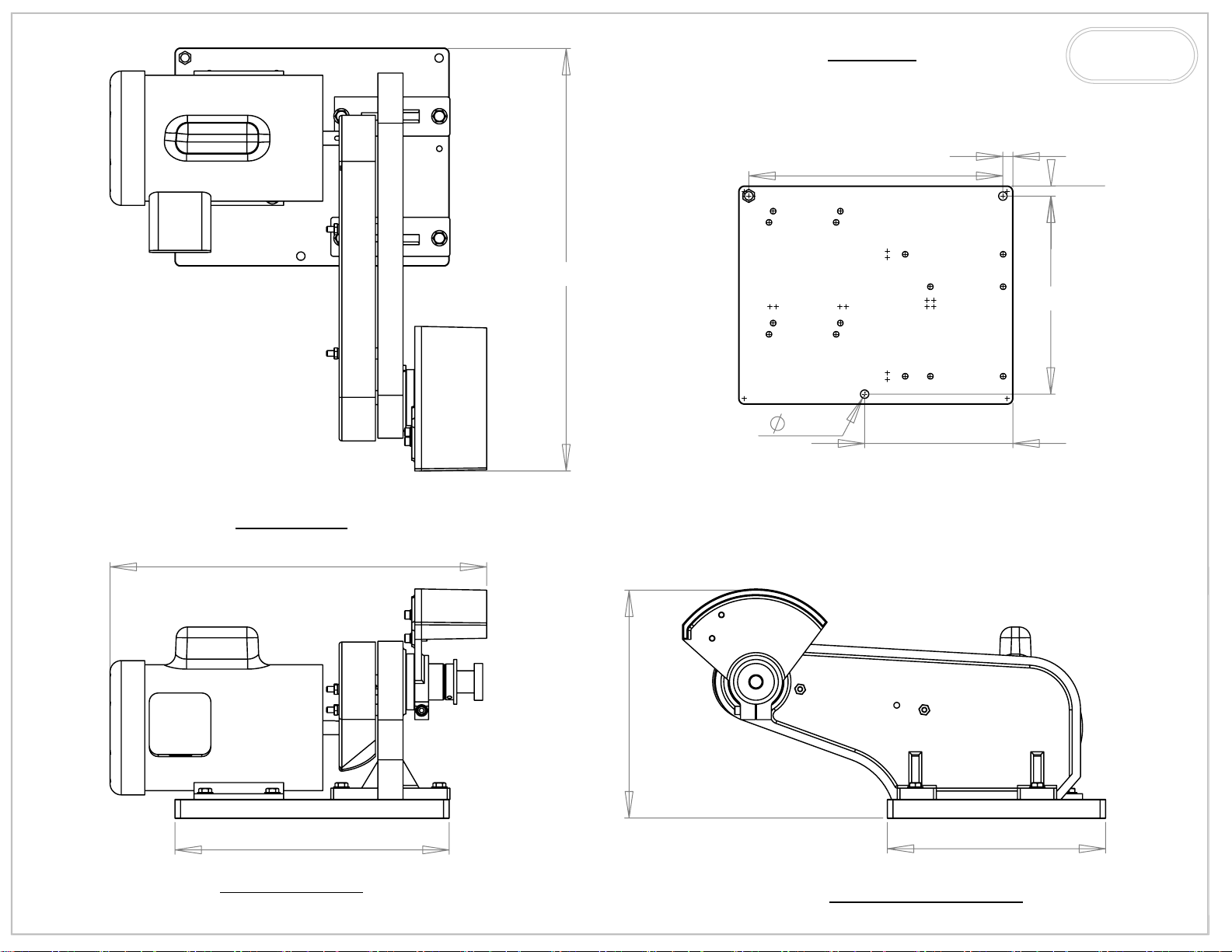
19.0
M600
FOOT PRINT
11.25
0.45
0.45
8.75
BURR KING
1220 TAMARA LANE
WARSAW, MO. 65355
TOP VIEW
17.0
12.25
10.50
0.38
6.625
9.75
FRONT VIEW
RIGHT SIDE VIEW
Page 14
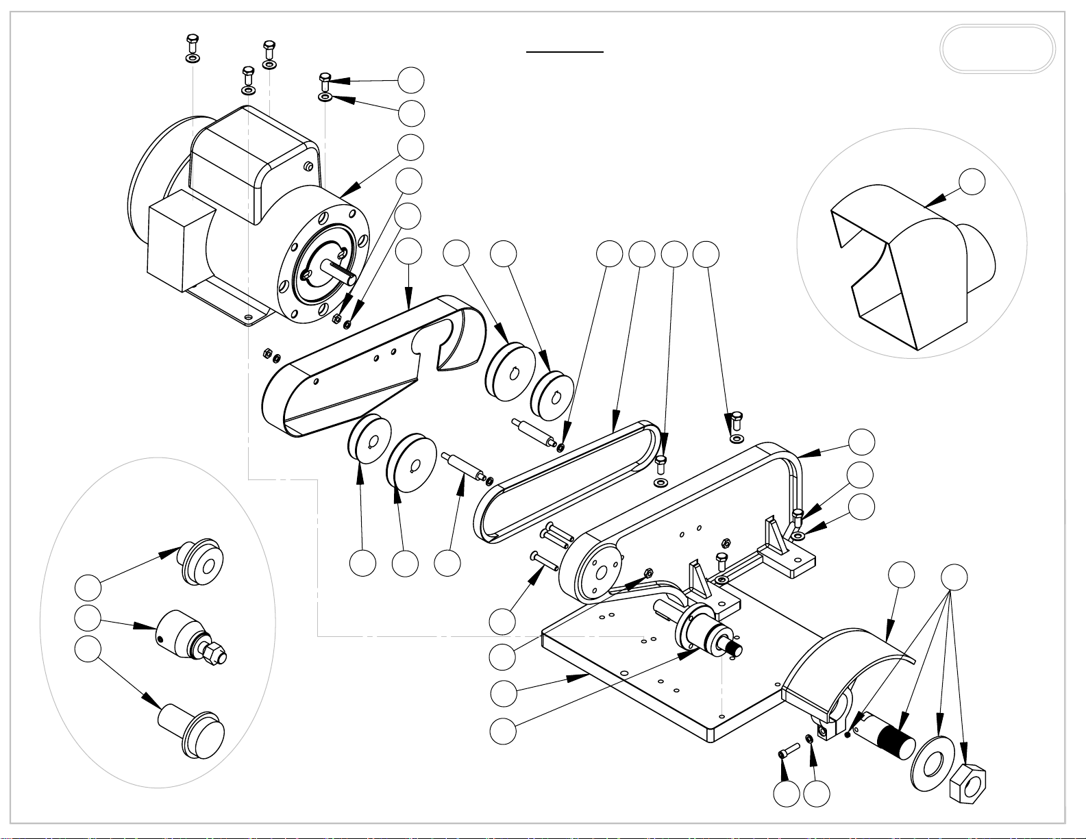
17
M800
BURR KING
SCHEMATIC
1220 TAMARA LANE
WARSAW, MO. 65355
3
OPTIONAL
18
12
8
16
14
15 8
13 4
OPTIONAL
19
3
2
4
3
20
21
22
15
14
11
12
7
5
10
1
6
89
Page 15
ITEM NO.
1 731
2 600
3 4
4 37
5 6
6 701
7
8 5
9 31
10
11
12 3
13 729
14 730
15 725
16 728
17 2
18
PART NUMBER
903K
WA14
728A
MOTOR
M800
DESCRIPTION
BASE, MACHINE
FRAME, MAIN
WASHER, 5/16 SAE ZINC PLTD
BOLT, 5/16-18x3/4 HEX HEAD
1/4-20 x 1 1/2 FH SOC
BEARING, CONTACT WHEEL ASSY
GUARD, CONTACT WHEEL
WASHER, 1/4 AN
SCREW 1/4-20x1 1/4 SHCS
ADAPTER 1- 1/4"
STUD, GUARD, V, BELT
NUT, 1/4-20 JAM, PLTD
BELT, V DRIVE
PULLEY, 3.0
PULLEY, 2.5
GUARD, V-BELT
BOLT, 5/16-18x1 1/2 HEX HEAD
CALL FACTORY*
QTY.
1
1
8
4
3
1
1
5
1
1
2
4
1
2
2
1
4
1
BURR KING
1220 TAMARA LANE
WARSAW, MO. 65355
ITEM NO.
19
ITEM NO.
20
21
22
PART NUMBER
DS8
PART NUMBER
WA1
WA12
WA2
* 011C ROCKER SWITCH FOR 1PH
OPTIONAL ATTACHMENT
DESCRIPTION
SCOOP, DUST
ACCESSORY WHEEL ADAPTERS
DESCRIPTION
ADAPTER 1"
ADAPTER 1/2"
ADAPTER 2"
QTY.
1
QTY.
1
1
1
Page 16
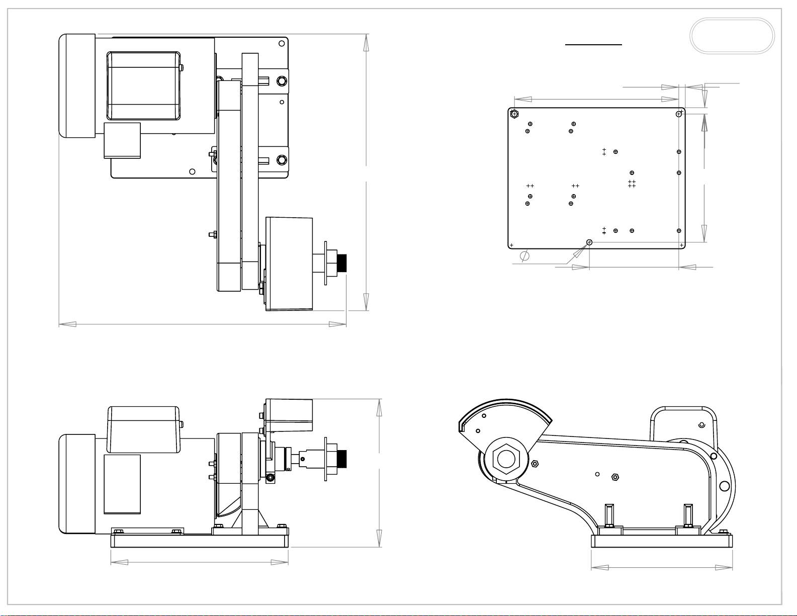
M800
FOOT PRINT
11.25
0.45
BURR KING
1220 TAMARA LANE
WARSAW, MO. 65355
0.45
20
20
10.23
0.38
8.75
6.18
12.25
9.75
Page 17
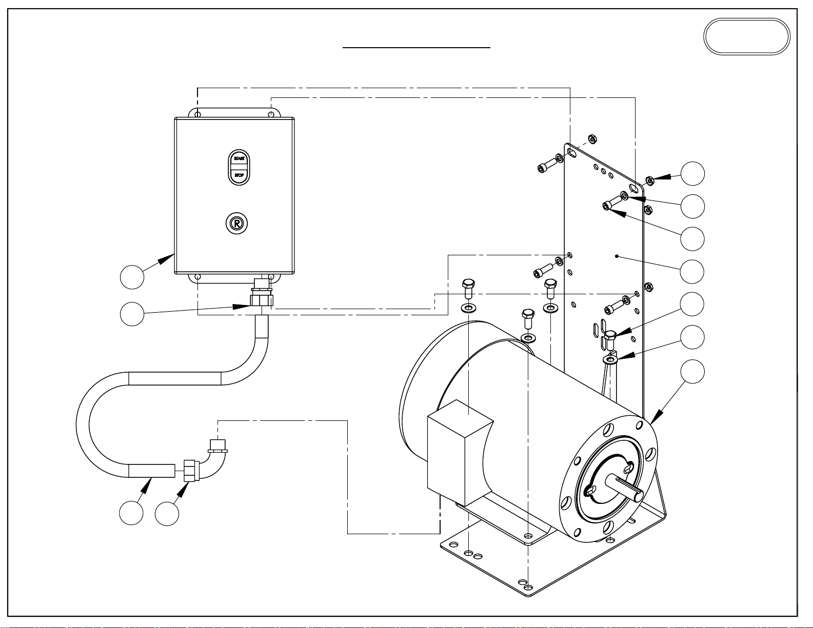
MAG STARTER
PARTS LIST
BURR KING
1220 TAMARA LANE
WARSAW, MO. 65355
7
5
6
8
9
11
1
4
3
2
10
Page 18
MAG STARTER
BURR KING
1220 TAMARA LANE
WARSAW, MO. 65355
ITEM NO.
1
2
3 4
4 37
5 5
6 209
7
8
9 775
10 776
11 020
PART NUMBER
MB-4C
MOTOR
4-0013
MS2A3
MS4A3
MS2B3
MS4B3
DESCRIPTION
BRACKET, MOUNTING, STARTER
CALL FACTORY FOR PART NUMBER
WASHER, 5/16 SAE ZINC PLTD
BOLT, 5/16-18x3/4 HEX HEAD
WASHER, 1/4 AN
SCREW, 1/4-20 X 3/4 ALLEN HEAD
NUT, KEP, 1/4-20
3/4HP-1HP, 220V
3/4HP-1HP, 440V
1.5HP-3HP, 220V
1.5HP-3HP, 440V
CONNECTOR, 3/8", STR, LIQ. TIGHT
CONNECTOR, 3/8", 90 DEG, LIQ. TIGHT
CONDUIT 3/8" LIQUID TIGHT
QTY.
1
1
4
4
4
4
4
1
1
1
1
Page 19
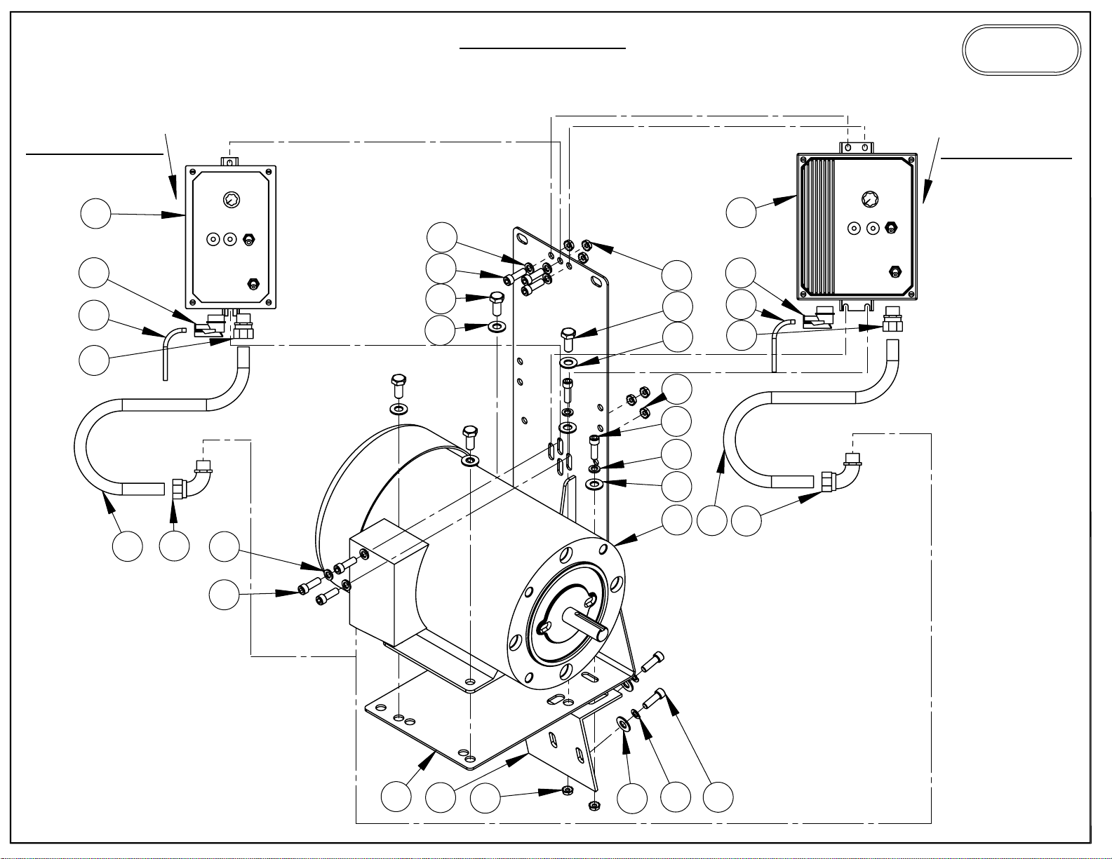
VARI SPEED
SINGLE PHASE
BURR KING
1220 TAMARA LANE
WARSAW, MO. 65355
3/4-1 HP
12
15
10
13
11
14
1.5-3 HP
16
6
5
9
4
6
7
9
4
7
5
6
4
8
11
15
10
13
14
5
1
2
7
4
3
5
Page 20
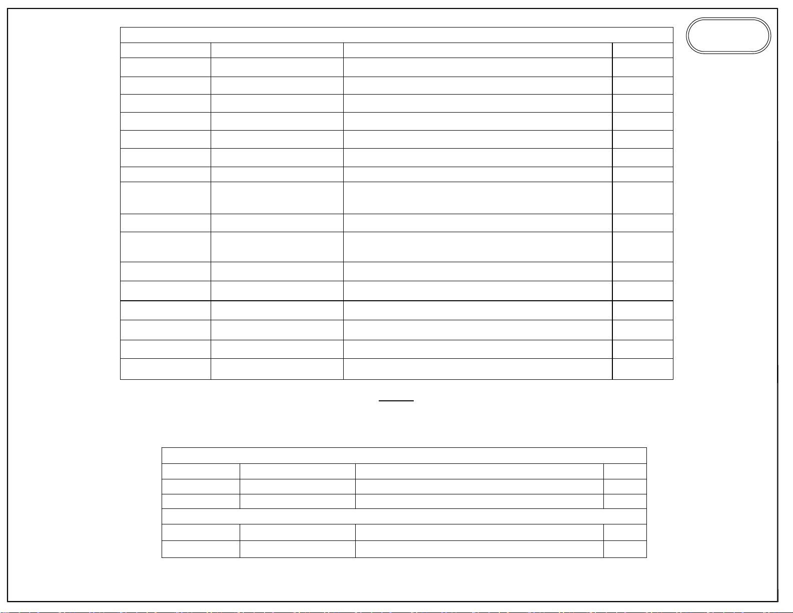
ITEM NO.
1
PART NUMBER
MB-4C
VARI SPEED
DESCRIPTION
BRACKET, MOUNTING, STARTER
QTY.
1
BURR KING
1220 TAMARA LANE
WARSAW, MO. 65355
2
3
941-3
5-0032
4 4
5 209
6 5
7
8
4-0013
100B-1725C
150B-1725C
9 37
10
015-1
017
11 020
12
864-1
13 775
14 776
15 643
16
862-3
BRACE, MB4 SUPPORT
WASHER, 1/4, LOCK, SPLIT, PLTD
WASHER, 5/16 SAE ZINC PLTD
SCREW, 1/4-20 X 3/4 ALLEN HEAD
WASHER, 1/4 AN
NUT, KEP, 1/4-20
1 HP MOTOR
1.5 HP MOTOR
BOLT, 5/16-18x3/4 HEX HEAD
120V CORD
220V CORD
CONDUIT 3/8" LIQUIDTIGHT
CONT. 115/220V 0.75-1HP
CONNECTOR, 3/8" STR, LIQ. TIGHT
CONNECTOR, 3/8", 90 DEG, LIQ. TIGHT
RELIEF, STRAIN 3/8" 90 DEG
CONT. 115/220V 1.5-3HP
1
2
8
10
8
8
1
4
1
1
1
1
1
1
1
ITEM NO.
12
16
15 3356
10
NOTE
FOR 3 PHASE CONTROLLER CALL FACTORY.
CE CERTIFICATION PART NUMBERS
ADD TO CONTROLLER
PART NUMBER
9974-6
9974-5
CE CORD
CHANGE PART
NO PLUG- CUSTOMER INSTALLED PLUG
DESCRIPTION
LINE FILTER
LINE FILTER
RELIEF, STRAIN
QTY.
1
1
1
1
 Loading...