

Burr Brown OPA244PA, OPA4344PA, OPA4344EA-2K5, OPA4344EA, OPA244NA-250 Datasheet
...
®
®
OPA4244
OPA244
OPA244
OPA2244
OPA2244
1
2
3
4
5
6
7
14
13
12
11
10
9
8
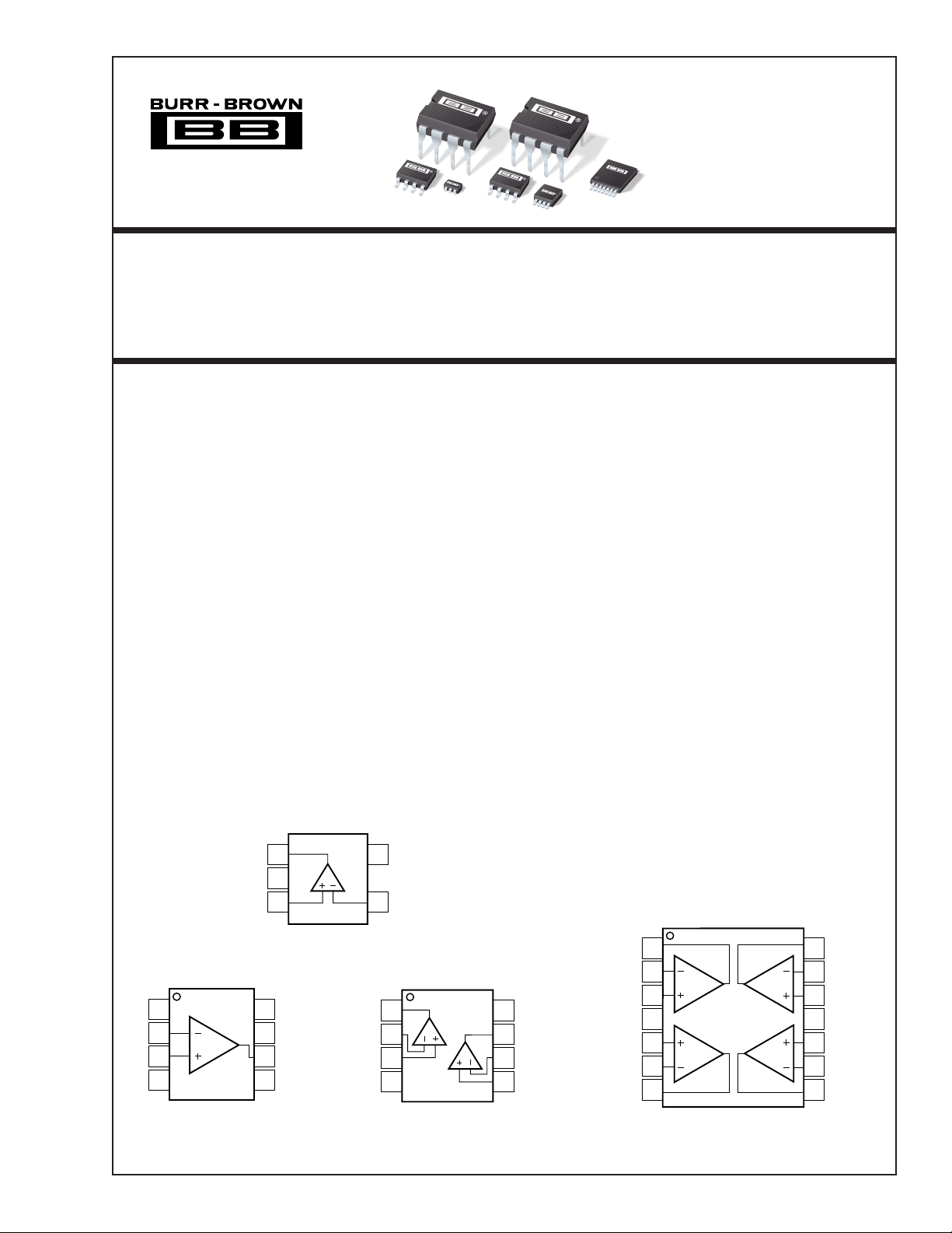
Output D
–Input D
+Input D
–V
+Input C
–Input C
Output C
Output A
–Input A
+Input A
+V
+Input B
–Input B
Output B
OPA4244
TSSOP-14
OPA244
OPA2244
OPA4244
Micro
Power,
OPERA TIONAL AMPLIFIERS
Micro
FEATURES
●
Micro
SIZE PACKAGES
OPA244 (Single): SOT-23-5
OPA2244 (Dual): MSOP-8
OPA4244 (Quad): TSSOP-14
●
Micro
POWER: IQ = 50µA/channel
● SINGLE SUPPLY OPERATION
● WIDE BANDWIDTH: 430 kHz
● WIDE SUPPLY RANGE:
Single Supply: 2.2V to 36V
Dual Supply: ±1.1V to ±18V
APPLICATIONS
● BATTERY POWERED SYSTEMS
● PORTABLE EQUIPMENT
● PCMCIA CARDS
● BATTERY PACKS AND POWER SUPPLIES
● CONSUMER PRODUCTS
OPA244
Out
1
V–
2
+In
3
Amplifier
V+
5
–In
4
Single-Supply
™
Series
DESCRIPTION
The OPA244 (single), OPA2244 (dual), and OPA4244 (quad)
op amps are designed for very low quiescent current
(50µA/channel), yet achieve excellent bandwidth. Ideal for
battery powered and portable instrumentation, all versions are
offered in micro packages for space-limited applications.
The dual and quad versions feature completely independent
circuitry for lowest crosstalk and freedom from interaction, even
when overdriven or overloaded.
The OPA244 series is easy to use and free from phase
inversion and overload problems found in some other op amps.
These amplifiers are stable in unity gain and excellent performance is maintained as they swing to their specified limits.
They can be operated from single (+2.2V to +36V) or dual
supplies (±1.1V to ±18V). The input common-mode voltage
range includes ground—ideal for many single supply applications. All versions have similar performance. However, there
are some differences, such as common-mode rejection. All
versions are interchangeable in most applications.
All versions are offered in miniature, surface-mount packages.
OPA244 (single version) comes in the tiny 5-lead SOT-23-5
surface mount, SO-8 surface mount, and 8-pin DIP. OPA2244
(dual version) is available in the MSOP-8 surface mount,
SO-8 surface-mount, and 8-pin DIP. The OPA4244 (quad)
comes in the TSSOP-14 surface mount. They are fully specified
from –40°C to +85°C and operate from –55°C to +125°C.
A SPICE Macromodel is available for design analysis.
SOT-23-5
OPA244
NC
1
–In
2
+In
3
V–
4
© 1999 Burr-Brown Corporation PDS-1437C Printed in U.S.A. December, 1999
8-Pin DIP, SO-8
International Airport Industrial Park • Mailing Address: PO Box 11400, Tucson, AZ 85734 • Street Address: 6730 S. Tucson Blvd., Tucson, AZ 85706 • Tel: (520) 746-1111
Twx: 910-952-1111 • Internet: http://www.burr-brown.com/ • Cable: BBRCORP • Telex: 066-6491 • FAX: (520) 889-1510 • Immediate Product Info: (800) 548-6132
8
7
6
5
NC
V+
Output
NC
Out A
–In A
+In A
V–
OPA2244
1
A
2
3
4
8-Pin DIP, SO-8, MSOP-8
B
V+
8
Out B
7
–In B
6
+In B
5
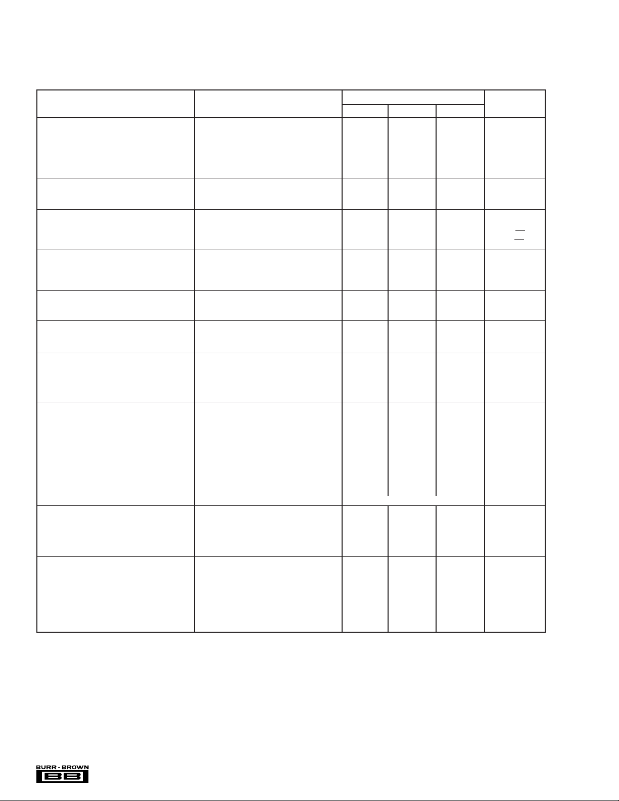
SPECIFICATIONS: VS = +2.6V to +36V
Boldface limits apply over the specified temperature range, TA = –40°C to +85°C
At TA = +25°C, RL = 20kΩ connected to ground, unless otherwise noted.
OPA244NA, PA, UA
PARAMETER CONDITION MIN TYP
OFFSET VOLTAGE
Input Offset Voltage V
= –40°C to 85°C ±2 mV
T
A
vs Temperature dV
vs Power Supply PSRR V
= –40°C to 85°C VS = +2.6V to +36V 50 µV/V
T
A
OS
/dT TA = –40°C to 85°C ±4 µV/°C
OS
VS = ±7.5V, VCM = 0 ±0.7 ±1.5 mV
= +2.6V to +36V 5 50 µV/V
S
INPUT BIAS CURRENT
Input Bias Current I
Input Offset Current I
B
OS
VCM = VS/2 –10 –25 nA
VCM = VS/2 ±1 ±10 nA
NOISE
Input Voltage Noise, f = 0.1kHz to 10kHz 0.4 µVp-p
Input Voltage Noise Density, f = 1kHz e
Current Noise Density, f = 1kHz i
n
n
INPUT VOLTAGE RANGE
Common-Mode Voltage Range V
Common-Mode Rejection CMRR V
= –40°C to 85°C VS = ±18V, VCM = –18V to +17.1V 84 dB
T
A
CM
= ±18V, VCM = –18V to +17.1V 84 98 dB
S
0 (V+) – 0.9 V
INPUT IMPEDANCE
Differential 106 || 2 Ω || pF
Common-Mode 10
OPEN-LOOP GAIN
Open-Loop Voltage Gain A
= –40°C to 85°C VO = 0.5V to (V+) – 0.9 86 dB
T
A
OL
VO = 0.5V to (V+) – 0.9 86 106 dB
FREQUENCY RESPONSE
Gain-Bandwidth Product GBW 430 kHz
Slew Rate SR G = 1 –0.1/+0.16 V/µs
Settling Time 0.01% 10V Step 150 µs
Overload Recovery Time V
• Gain = V
IN
S
OUTPUT
A
Voltage Output, Positive V
= –40°C to 85°C A
T
A
Voltage Output, Negative A
= –40°C to 85°C A
T
A
Voltage Output, Positive A
= –40°C to 85°C A
T
A
Voltage Output, Negative A
= –40°C to 85°C A
T
A
Short-Circuit Current I
Capacitive Load Drive C
O
SC
LOAD
≥ 80dB, RL = 20kΩ to VS/2 (V+) – 0.9 (V+) – 0.75 V
OL
≥ 80dB, RL = 20kΩ to VS/2 (V+) – 0.9 (V+) – 0.75 V
OL
≥ 80dB, RL = 20kΩ to VS/2 0.5 0.2 V
OL
≥ 80dB, RL = 20kΩ to VS/2 0.5 0.2 V
OL
≥ 80dB, RL = 20kΩ to Ground (V+) – 0.75 V
OL
≥ 80dB, RL = 20kΩ to Ground (V+) – 0.75 V
OL
≥ 80dB, RL = 20kΩ to Ground 0.1 V
OL
≥ 80dB, RL = 20kΩ to Ground 0.1 V
OL
See Typical Curve
POWER SUPPLY
Specified Voltage Range V
Minimum Operating Voltage +2.2 V
Quiescent Current I
= –40°C to 85°C IO = 0 70 µA
T
A
S
Q
TA = –40°C to 85°C +2.6 +36 V
IO = 0 50 60 µA
TEMPERATURE RANGE
Specified Range –40 85 °C
Operating Range –55 125 °C
Storage Range –65 150 °C
Thermal Resistance
SOT-23-5 Surface-Mount 200 °C/W
θ
JA
SO-8 Surface-Mount 150 °C/W
8-Pin DIP 100 °C/W
NOTE: (1) V
= +15V.
S
(1)
MAX UNITS
22 nV/√Hz
40 fA/√Hz
9
|| 2 Ω || pF
8 µs
–25 /+12 mA
The information provided herein is believed to be reliable; however, BURR-BROWN assumes no responsibility for inaccuracies or omissions. BURR-BROWN assumes
no responsibility for the use of this information, and all use of such information shall be entirely at the user’s own risk. Prices and specifications are subject to change
without notice. No patent rights or licenses to any of the circuits described herein are implied or granted to any third party. BURR-BROWN does not authorize or warrant
any BURR-BROWN product for use in life support devices and/or systems.
®
OPA244, 2244, 4244
2
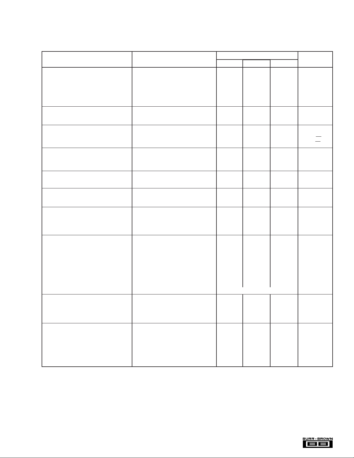
SPECIFICATIONS: VS = +2.6V to +36V
Boldface limits apply over the specified temperature range, TA = –40°C to +85°C
At TA = +25°C, RL = 20kΩ connected to ground, unless otherwise noted.
OPA2244EA, PA, UA
PARAMETER CONDITION MIN TYP
OFFSET VOLTAGE
Input Offset Voltage V
= –40°C to 85°C ±2 mV
T
A
vs Temperature dV
vs Power Supply PSRR V
= –40°C to 85°C VS = +2.6V to +36V 50 µV/V
T
A
Channel Separation 140 dB
OS
/dT TA = –40°C to 85°C ±4 µV/°C
OS
VS = ±7.5V, VCM = 0 ±0.7 ±1.5 mV
= +2.6V to +36V 5 50 µV/V
S
INPUT BIAS CURRENT
Input Bias Current I
Input Offset Current I
B
OS
VCM = VS/2 –10 –25 nA
VCM = VS/2 ±1 ±10 nA
NOISE
Input Voltage Noise, f = 0.1kHz to 10kHz 0.4 µVp-p
Input Voltage Noise Density, f = 1kHz e
Current Noise Density, f = 1kHz i
n
n
INPUT VOLTAGE RANGE
Common-Mode Voltage Range V
Common-Mode Rejection CMRR V
= –40°C to 85°C VS = ±18V, VCM = –18V to +17.1V 72 dB
T
A
CM
= ±18V, VCM = –18V to +17.1V 72 98 dB
S
0 (V+) – 0.9 V
INPUT IMPEDANCE
Differential 106 || 2 Ω || pF
Common-Mode 10
OPEN-LOOP GAIN
Open-Loop Voltage Gain A
= –40°C to 85°C VO = 0.5V to (V+) – 0.9 86 dB
T
A
OL
VO = 0.5V to (V+) – 0.9 86 106 dB
FREQUENCY RESPONSE
Gain-Bandwidth Product GBW 430 kHz
Slew Rate SR G = 1 –0.1/+0.16 V/µs
Settling Time 0.01% 10V Step 150 µs
Overload Recovery Time V
• Gain = V
IN
S
OUTPUT
A
Voltage Output, Positive V
= –40°C to 85°C A
T
A
Voltage Output, Negative A
= –40°C to 85°C A
T
A
Voltage Output, Positive A
= –40°C to 85°C A
T
A
Voltage Output, Negative A
= –40°C to 85°C A
T
A
Short-Circuit Current I
Capacitive Load Drive C
O
SC
LOAD
≥ 80dB, RL = 20kΩ to VS/2 (V+) – 0.9 (V+) – 0.75 V
OL
≥ 80dB, RL = 20kΩ to VS/2 (V+) – 0.9 (V+) – 0.75 V
OL
≥ 80dB, RL = 20kΩ to VS/2 0.5 0.2 V
OL
≥ 80dB, RL = 20kΩ to VS/2 0.5 0.2 V
OL
≥ 80dB, RL = 20kΩ to Ground (V+) – 0.75 V
OL
≥ 80dB, RL = 20kΩ to Ground (V+) – 0.75 V
OL
≥ 80dB, RL = 20kΩ to Ground 0.1 V
OL
≥ 80dB, RL = 20kΩ to Ground 0.1 V
OL
See Typical Curve
POWER SUPPLY
Specified Voltage Range V
Minimum Operating Voltage +2.2 V
Quiescent Current (per amplifier) I
= –40°C to 85°C IO = 0 63 µA
T
A
S
Q
TA = –40°C to 85°C +2.6 +36 V
IO = 0 40 50 µA
TEMPERATURE RANGE
Specified Range –40 85 °C
Operating Range –55 125 °C
Storage Range –65 150 °C
Thermal Resistance
MSOP-8 Surface-Mount 200 °C/W
θ
JA
SO-8 Surface-Mount 150 °C/W
8-Pin DIP 100 °C/W
NOTE: (1) V
= +15V.
S
(1)
MAX UNITS
22 nV/√Hz
40 fA/√Hz
9
|| 2 Ω || pF
8 µs
–25 /+12 mA
®
3
OPA244, 2244, 4244
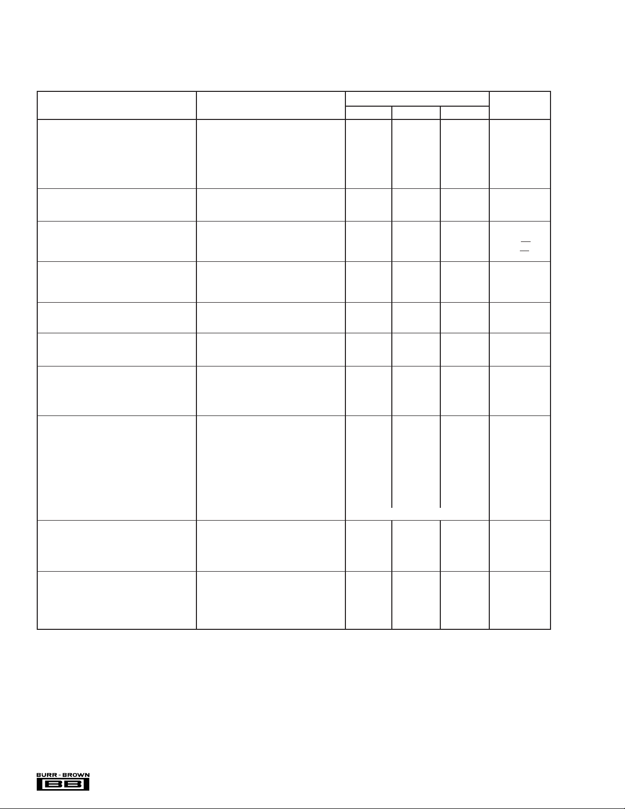
SPECIFICATIONS: VS = +2.6V to +36V
Boldface limits apply over the specified temperature range, TA = –40°C to +85°C
At TA = +25°C, RL = 20kΩ connected to ground, unless otherwise noted.
OPA4244EA
PARAMETER CONDITION MIN TYP
OFFSET VOLTAGE
Input Offset Voltage V
= –40°C to 85°C ±2 mV
T
A
vs Temperature dV
vs Power Supply PSRR V
= –40°C to 85°C VS = +2.6V to +36V 50 µV/V
T
A
Channel Separation 140 dB
OS
/dT TA = –40°C to 85°C ±4 µV/°C
OS
VS = ±7.5V, VCM = 0 ±0.7 ±1.5 mV
= +2.6V to +36V 5 50 µV/V
S
INPUT BIAS CURRENT
Input Bias Current I
Input Offset Current I
B
OS
VCM = VS/2 –10 –25 nA
VCM = VS/2 ±1 ±10 nA
NOISE
Input Voltage Noise, f = 0.1kHz to 10kHz 0.4 µVp-p
Input Voltage Noise Density, f = 1kHz e
Current Noise Density, f = 1kHz i
n
n
INPUT VOLTAGE RANGE
Common-Mode Voltage Range V
Common-Mode Rejection CMRR V
= –40°C to 85°C VS = ±18V, VCM = –18V to +17.1V 82 dB
T
A
CM
= ±18V, VCM = –18V to +17.1V 82 104 dB
S
0 (V+) – 0.9 V
INPUT IMPEDANCE
Differential 106 || 2 Ω || pF
Common-Mode 10
OPEN-LOOP GAIN
Open-Loop Voltage Gain A
= –40°C to 85°C VO = 0.5V to (V+) – 0.9 86 dB
T
A
OL
VO = 0.5V to (V+) – 0.9 86 106 dB
FREQUENCY RESPONSE
Gain-Bandwidth Product GBW 430 kHz
Slew Rate SR G = 1 –0.1/+0.16 V/µs
Settling Time 0.01% 10V Step 150 µs
Overload Recovery Time V
• Gain = V
IN
S
OUTPUT
A
Voltage Output, Positive V
= –40°C to 85°C A
T
A
Voltage Output, Negative A
= –40°C to 85°C A
T
A
Voltage Output, Positive A
= –40°C to 85°C A
T
A
Voltage Output, Negative A
= –40°C to 85°C A
T
A
Short-Circuit Current I
Capacitive Load Drive C
O
SC
LOAD
≥ 80dB, RL = 20kΩ to VS/2 (V+) – 0.9 (V+) – 0.75 V
OL
≥ 80dB, RL = 20kΩ to VS/2 (V+) – 0.9 (V+) – 0.75 V
OL
≥ 80dB, RL = 20kΩ to VS/2 0.5 0.2 V
OL
≥ 80dB, RL = 20kΩ to VS/2 0.5 0.2 V
OL
≥ 80dB, RL = 20kΩ to Ground (V+) – 0.75 V
OL
≥ 80dB, RL = 20kΩ to Ground (V+) – 0.75 V
OL
≥ 80dB, RL = 20kΩ to Ground 0.1 V
OL
≥ 80dB, RL = 20kΩ to Ground 0.1 V
OL
See Typical Curve
POWER SUPPLY
Specified Voltage Range V
Minimum Operating Voltage +2.2 V
Quiescent Current (per amplifier) I
= –40°C to 85°C IO = 0 70 µA
T
A
S
Q
TA = –40°C to 85°C +2.6 +36 V
IO = 0 40 60 µA
TEMPERATURE RANGE
Specified Range –40 85 °C
Operating Range –55 125 °C
Storage Range –65 150 °C
Thermal Resistance
TSSOP-14 Surface Mount 100 °C/W
θ
JA
NOTE: (1) VS = +15V.
(1)
MAX UNITS
22 nV/√Hz
40 fA/√Hz
9
|| 2 Ω || pF
8 µs
–25/ +12 mA
®
OPA244, 2244, 4244
4
 Loading...