

Burr Brown ISO518P-U, ISO518P Datasheet
®
ISO518
ISO518
For most current data sheet and other product
information, visit www.burr-brown.com
ISOLATED DIGITAL COUPLERS
ISO518
Bidirectional
FEATURES
● LOW POWER CONSUMPTION:
< 12mW per Channel
● 1500Vrms ISOLATION:
100% Tested by Partial Discharge
● DOUBLE BUFFERED DESIGN FOR
EASY INTEGRATION INTO BUS-BASED
SYSTEMS
● TRI-STATE OUTPUTS
● 24-PIN PDIP OR GULL WING PACKAGES
● 2MWORDS/S TRANSFER RATE
APPLICATIONS
● PARALLEL ADCs/DACs
● DIGITAL INTERFACES
● DIGITAL TRANSMISSION
● GROUND-LOOP ISOLATION
L
L
S
A
H
T
I
C
F
H
T
DATA
I/O
A
T
C
H
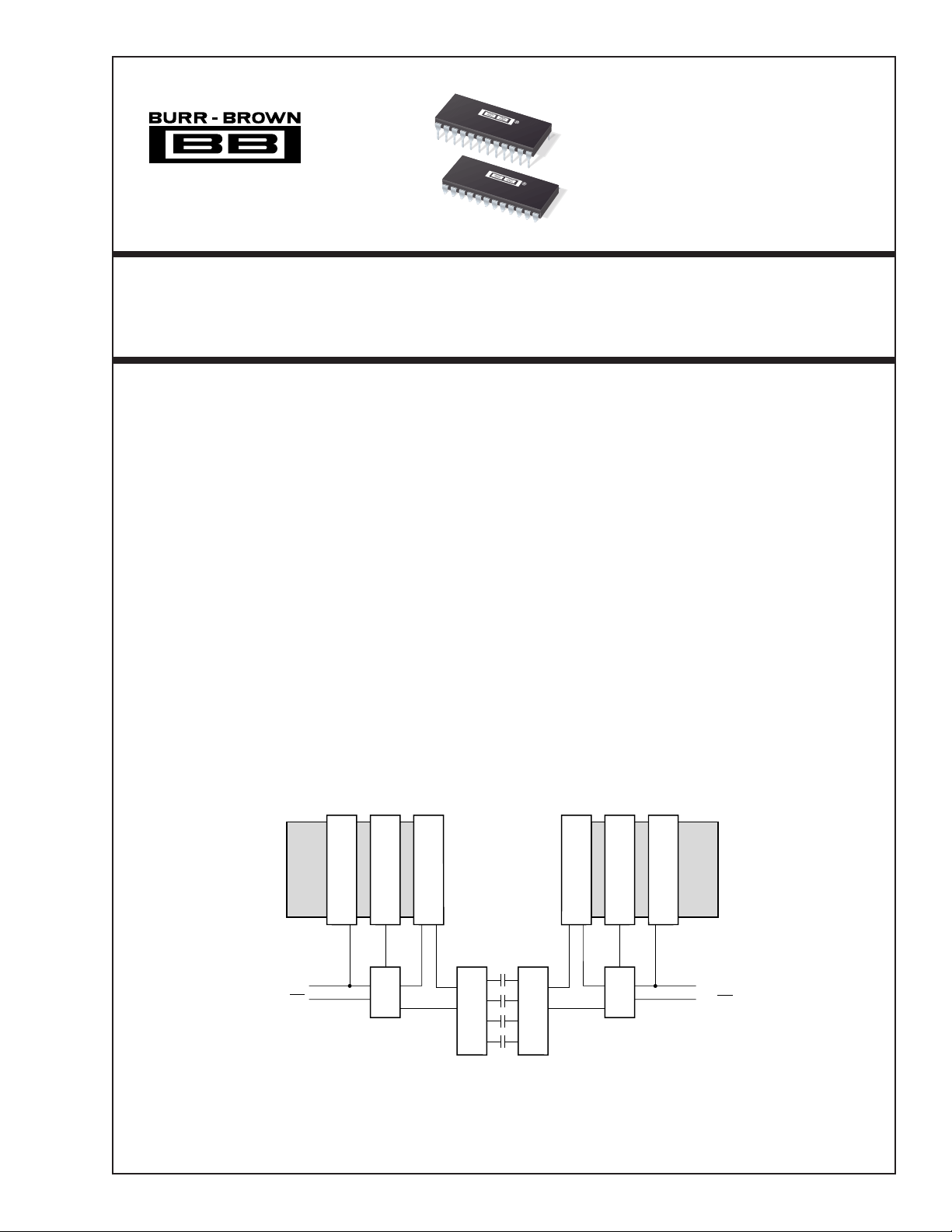
DESCRIPTION
The ISO518 is an 8-channel, isolated, bidirectional
digital coupler based on the Burr-Brown capacitive
barrier technology.
The ISO518 is designed with input and output buffers
for ease of integration into a µP bus system. All data
pins are I/O under the control of the TX pins. Input
and output buffers are controlled by the latch enable
pins. This feature of the ISO518, which allows multiple access to a data bus, requires extra circuitry when
using an alternative solution.
The ISO518 will transfer an 8-bit word at rates up to
2Mwords/s without the skew problems associated in
implementing this function with optocouplers. The
ISO518 is available in 24-pin PDIP or 24-pin Gull
Wing packages. Both are specified for operation from
–40°C to +85°C.
S
L
H
I
F
T
L
A
A
T
C
H
DATA
T
I/O
C
H
LEA
TXA/RXA
ISO518 Functional Block Diagram
International Airport Industrial Park • Mailing Address: PO Box 11400, Tucson, AZ 85734 • Street Address: 6730 S. Tucson Blvd., Tucson, AZ 85706 • Tel: (520) 746-1111
Twx: 910-952-1111 • Internet: http://www.burr-brown.com/ • Cable: BBRCORP • Telex: 066-6491 • FAX: (520) 889-1510 • Immediate Product Info: (800) 548-6132
©
1998 Burr-Brown Corporation PDS-1423B Printed in U.S.A. June, 1999
1
LEB
TXB/RXB
ISO518
®

SPECIFICATIONS
At TA = +25°C, and VS = +5V, unless otherwise noted.
ISO518P, P-U
PARAMETER CONDITIONS MIN TYP MAX UNITS
ISOLATION
Rated Voltage, Continuous V
ISO
Partial Discharge Voltage 1s, 5 x 5pC/cycle
Barrier Impedance >10
Leakage Current 240V, 60Hz 1 µA
Creepage Distance PDIP = “P” and “U” Package 11 mm
Internal Isolation Distance PDIP = “P” and “U” Package 0.1 mm
Transient Recovery Time 5kV/µs Edge 1 µs
DC CHARACTERISTICS
High Level Input Voltage V
Low Level Input Voltage V
Input Leakage Current I
Input Capacitance C
High Level Output Voltage V
Low Level Output Voltage V
Output Short-Circuit Current I
IH
IL
L
IN
OH
OL
OS
TIMING
LE Width (LOW) t
LE Width (HIGH) t
Data Set-Up to LEA/B t
Data Hold from LEA/B t
Propagation Delay t
Data Output Delay t
Output Rise and Fall Time t
Output Enable t
Output Disable t
WL
WH
SU
H
PD
LEO HIGH to Data Out Channels 35 ns
OD
RF
OE to Data Valid HIGH or LOW 35 ns
EN
DIS
Max Data Transfer Rate 2 Mw/s
Skew Between Any Two Channels 5 ns
POWER
Supply Voltage V
Supply Current I
Supply Current I
, V
SA
SB
SA/ B
SB/ A
TEMPERATURE RANGE
Operating –40 +85 °C
Storage –40 +125 °C
Thermal Resistance,
θ
JA
NOTES: (1) All devices receive a 1s test. Failure criterion is > 5pC pulses of ≥ 5pC per cycle. (2) Logic inputs are HCT-type and thresholds are a function of power supply
voltage with approximately 400mV hysteresis.
50Hz, 60Hz 1500 Vrms
(1)
2500 Vrms
14
|| 10 Ω/pF
2500V, 50Hz 12 µA
See Note 2 2 V
See Note 2 0.8 V
5nA
5pF
IOH = 6mA VS –1 V
IOL = 6mA 0.4 V
IS, max 30 mA
100 ns
15 ns
LEA/B HIGH to LOW 0 ns
LEA/B HIGH to LOW 20 ns
LEA/B LOW to Data Out 520 ns
10% to 90% Load = 50pF 9 14 ns
OE to Data HI-Z 35 ns
Either Side 4.5 5.5 V
Transmit Side DC 5 10 mA
Transmit Side DC Max Rate 7 15 mA
Receive Side DC 8 12 mA
Receive Side Max Rate 12 20 mA
+75 °C/W
The information provided herein is believed to be reliable; however, BURR-BROWN assumes no responsibility for inaccuracies or omissions. BURR-BROWN
assumes no responsibility for the use of this information, and all use of such information shall be entirely at the user’s own risk. Prices and specifications are subject
to change without notice. No patent rights or licenses to any of the circuits described herein are implied or granted to any third party. BURR-BROWN does not
authorize or warrant any BURR-BROWN product for use in life support devices and/or systems.
®
ISO518
2
 Loading...