

Page 1
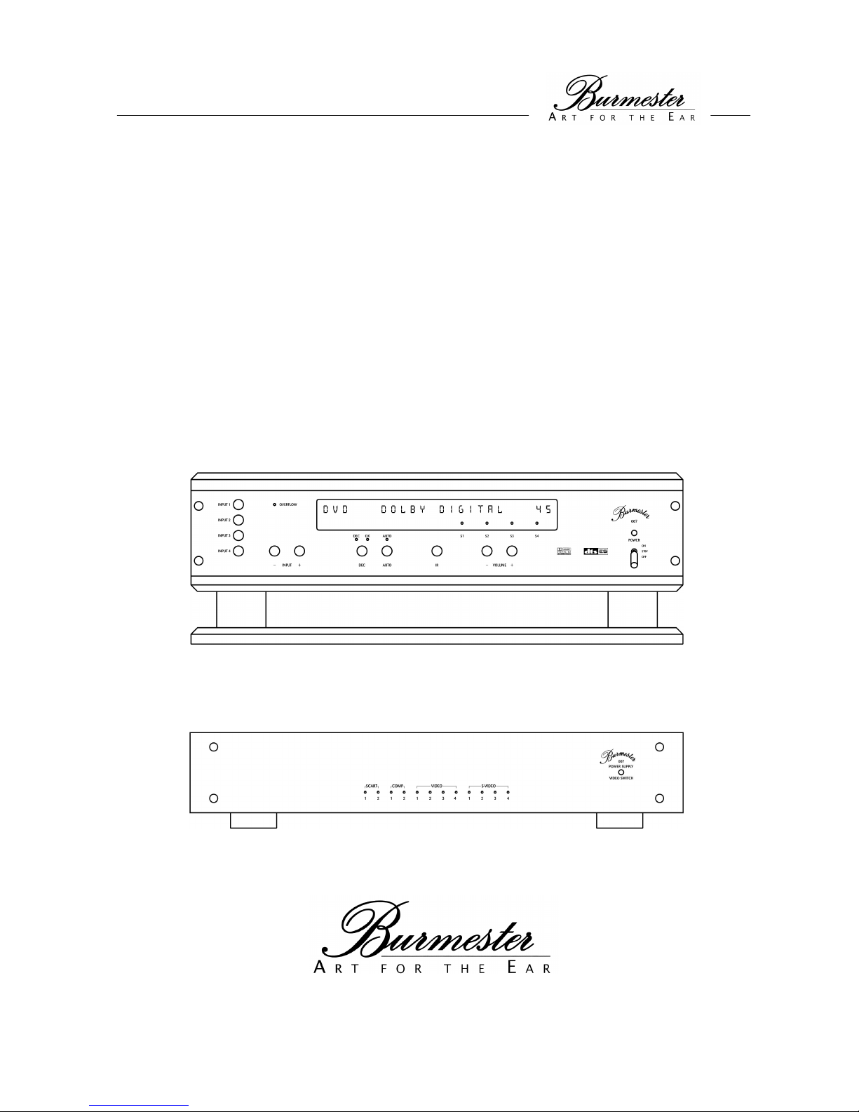
OPERATING
INSTRUCTIONS
SURROUND PROCESSOR
007
HIGH END MADE IN GERMANY
BURMESTER AUDIOSYSTEME GMBH • KOLONNENSTR. 30G • 10829 BERLIN
TEL 030/78 79 68 - 0 • FAX 030/78 79 68 - 68 • www.burmester.de
Page 2

Page 3

Dear Audiophile,
Thank you for choosing this Burmester audio component. We sincerely appreciate your trust in us. You have
purchased a unit which excells in musical fidelity and combines uncompromising manufacturing quality
with technical innovation and the highest degree of operating flexibility.
We recommend reading this user manual in its entirety before initial operation. It will enable you to make full
use of all capabilities of this outstanding audiophile instrument. Should you have any further questions,
please contact your dealer or us directly.
You decide if we meet the demands of producing high-end components. We offer an additional service
which also demonstrates high-end quality.
Talk to us about your special requests, even if they seem out of the ordinary. We happily accept technically
reasonable challenges.
Enjoy your enhanced listening pleasure.
Your Burmester Team
Page 4

C O N T E N T S
START-UP
Unpacking the units 1
Setting up 1
Commencing operation 2
Precautions 2
Technical Data 3
Licence notice 3
VIEWS OF UNITS
Front view 4
Rear view 5
CONTROLS AND FUNCTIONS
Control elements of power supply unit 6
Control elements of surround processor 6-7
The display 7
CONNECTIONS
Connections of power supply unit 8
Connections of surround processor 9
REMOTE CONTROL 10-11
LOUDSPEAKER SYSTEMS AND SET-UP 12-13
CONFIGURATION MENUS
Activation of MENUS 15
Navigating within MENUS 15
Exiting MENUS 15
THE GLOBAL MENU
Overview and brief description of menu items 16
Loudspeaker configuration 17
Loudspeaker distance 18
5.1 surround output 19
Configurating the inputs 20
Input sensitivity of analog inputs 21
Pin selection of XLR outputs 22
Start-up volume 22
Saving settings of the GLOBAL MENU 23
Loading factory settings 23
Page 5

C O N T E N T S
THE SETUP MENU
Overview and brief description of menu items 24
Loudspeaker level 25
Level LFE 25
Dynamic range 26
Surround mode of inputs 27
Display Off mode 27
Dolby Digital Dual mode 28
DTS Neo mode 28
Dolby Pro Logic II mode 28
Dolby Pro Logic II Panorama 29
Dolby Pro Logic II Center Width 29
Dolby Pro Logic II Dimension 29
Saving settings of the SETUP MENU 30
Loading factory settings 30
THE QUICK MENU
Overview and brief description of menu items 31
APPENDIX
A Factory settings
B Input names
C Facts about surround
Page 6

Page 7
1
UNPACKING THE UNITS
Please make sure that all items are enclosed. Should any of the contents be missing, please contact your dealer.
Contents The shipping carton contains:
• 2 packaging containers (surround processor and power supply unit)
• 1 base plate
• 4 carbon fiber springs
• 1 power cord
• 1 connecting cable, power supply unit to basic unit (power supply cable)
• 1 remote control
• 1 owner’s manual
Packaging We recommend keeping the original packaging material in case of a move or future
shipping.
SETTING UP THE UNITS
Carefully remove the surround processor and the power supply unit from the shipping cartons and set the units up in
appropriate places. Please make sure that the ventilation slits on the sides of the units remain unobstructed, so that
air ventilation is ensured.
In order to minimize undesired modulations, the power supply unit should not be set up in the immediate vicinity of
the surround processor or other components of your system, incl. connecting and power supply cables.
Set up variations
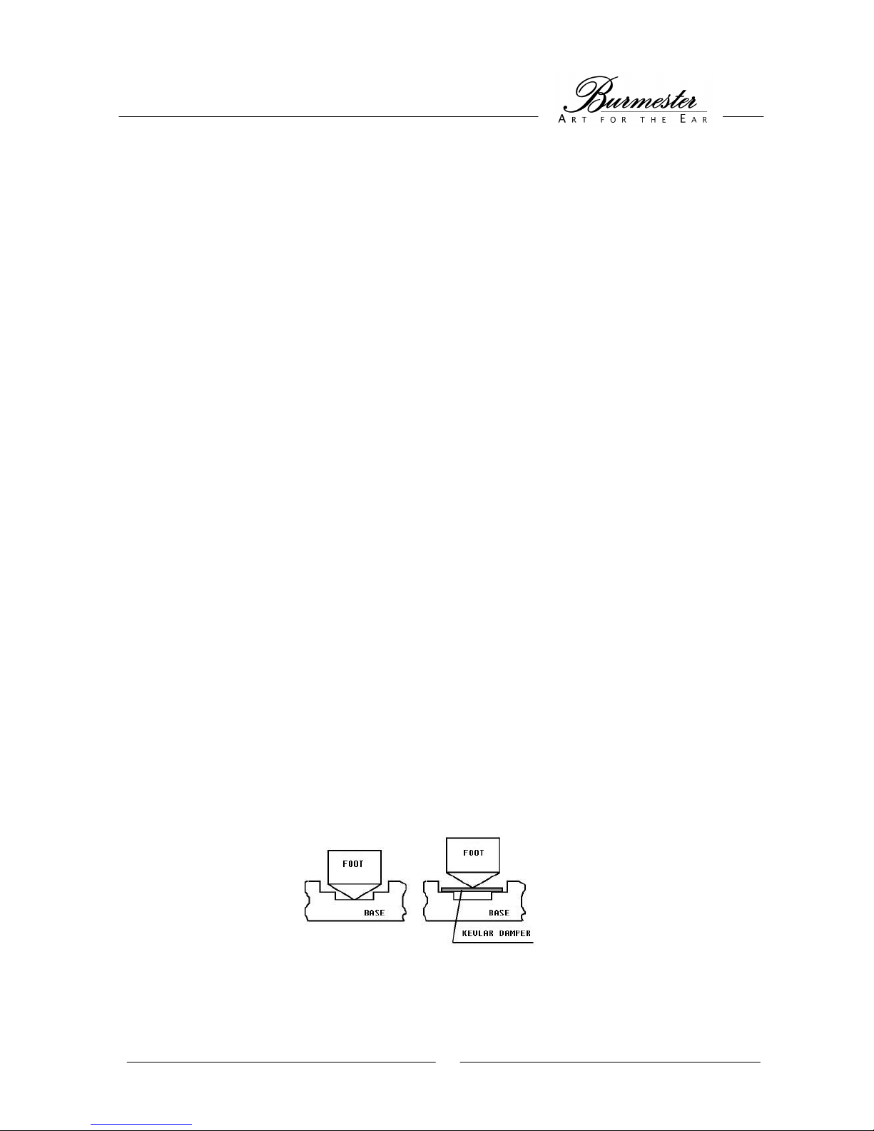
The feet of the surround processor are constructed as spikes. They can either be placed directly on the aluminum of
the base plate or on the supplied carbon fiber springs. Using the carbon fiber springs additionally decouples the
entire housing acoustically from the ground surface.
We recommend placing the surround processor onto the base plate (8) with the carbon fiber springs.
Page 8

2
COMMENCING OPERATION
Make sure that the MAINS switch (43) on the rear of the power supply unit and the POWER switch (17) on front of
the surround processor are set to OFF.
Connect the two units with the supplied power supply cable.
Carefully insert one end of the cable into the POWER SUPPLY jack (19) on the rear of the surround processor.
Make sure that the spigot of the plug is securely in the guide groove of the jack. Then screw the plug tight. Now
connect the other end of the cable in the same way with the POWER SUPPLY jack (51) on the rear of the power
supply unit.
Connect all other components of your system with the units.
Connect the power cable with the MAINS socket (42) on the rear of the power supply unit. Then plug the power cord
into the power outlet.
Switch the MAINS switch (43) on the rear of the power supply unit to ON - the POWER SUPPLY LED (38) of the
power supply unit illuminates green.
Switch the POWER switch (17) on front of the surround processor to ON (upper position) - the POWER LED (18)
above the POWER switch and the POWER SUPPLY LED (38) of the power supply unit will now illuminate red. The
display will show at least the selected input (left) and the selected volume (right).
The surround processor is now ready for operation.
GENERAL ADVICE
Reset If the unit does not respond to the control buttons, it can be reset to normal operating
conditions by switching it off and back on using the MAINS switch (43) on the rear of the
power supply unit.
Lightning During the summer months, malfunctions often occur due to voltage spikes in the power
lines after lightning strikes. Completely unplugging the power cord offers the only effective
protection. Merely switching the MAINS switch (43) off does not suffice, since voltage
spikes are able to arc over seperated contacts.
Interconnects We custom-make balanced and unbalanced interconnect cables of any length to ensure
highest-quality signal paths for the surround processor 007. The impedance of our cables is
ideally matched to all Burmester components. For optimum power supply we recommend
our triple-shielded power cord BURMESTER POWER.
Fuses The fuses are located inside the unit and should only be changed by an expert.
MAINS voltage The bridge for selecting MAINS voltage is located inside the unit. Any neccessary
adjustments of the setting should only be performed by an authorized dealer.
PLEASE NOTE: Always unplug the AC cord before removing the housing cover - risk of electric shock!
Page 9
3
TECHNICAL DATA
Basic unit Dimensions (WxHxD): 450x160x340 mm (incl. base plate)
Weight: ca. 28kg (incl. base plate)
Power supply unit Dimensions (WxHxD): 482x95x340 mm
Weight: ca. 10kg
Power consumption: ON: max. 60W STBY: 4W
Fuses: 200/240V 1x1A/ time-lag , 2x50mA/ time-lag
110/127V 2x1,6A/ time-lag , 2x100mA/ time-lag
PLEASE NOTE: The dimensions do not include the space needed for the plugs of interconnect cables.
LICENCE NOTICE
Manufactured under license from Dolby Laboratories.
“Dolby”, “Pro Logic” and the double-D symbol are trademarks of Dolby Laboratories.
Manufactured under license from Digital Theater Systems, Inc. US Pat. No. 5,451,942,
5,956,674, 5,978,762 and other worldwide patend issued and pending. “DTS”, “DTS-ES
Extended Surround” and “NEO:6” are trademarks of Digital Theater Systems, Inc. © 1996, 2000
Digital Thaeter Systems, Inc. All rights reserved.
Page 10
4
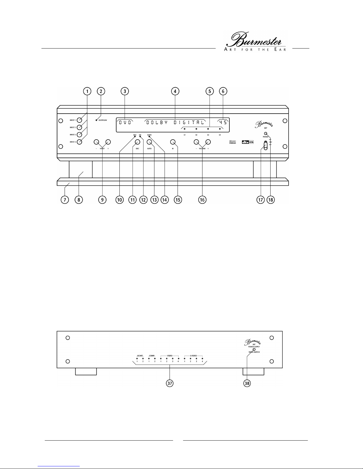
FRONT VIEW SURROUND PROCESSOR
(1) Buttons for direct input selection (10) DECODE LED
(2) LED for overload indication (11) DECODE button
(3) Input indicator (12) DECODE OK LED
(4) Decode indicator (13) AUTO DECODE button
(5) LEDs for selected SETUPs (14) AUTO DECODE LED
(6) Volume indicator (15) IR receiver
(7) Unit base (16) Volume buttons
(8) Unit foot (17) Power switch
(9) Input selection buttons (18) Power LED
FRONT VIEW POWER SUPPLY UNIT AND VIDEO SWITCHING UNIT
(37) LEDs for selected video input (38) POWER SUPPLY LED
Page 11
5
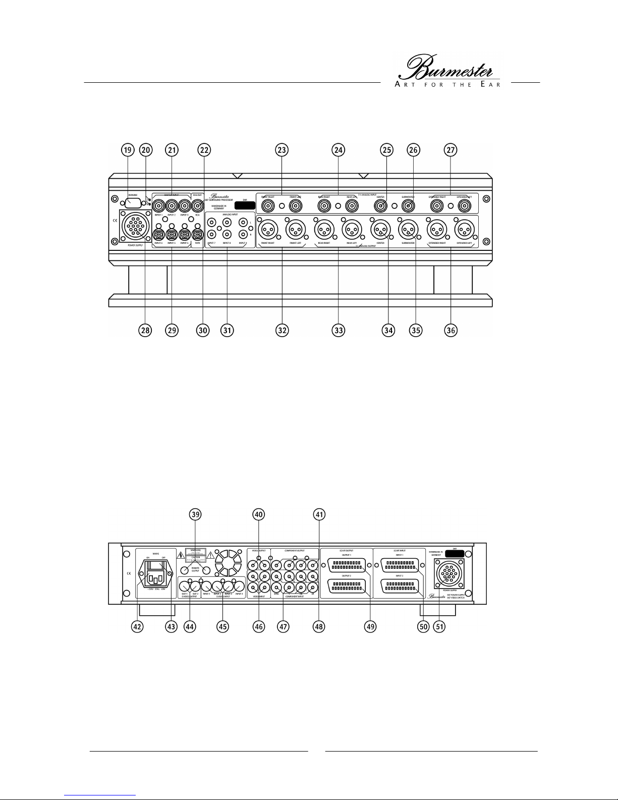
REAR VIEW SURROUND PROCESSOR
(19) BURLINK interface (28) POWER SUPPLY connection
(20) RECEIVE / TRANSMIT LEDs for BURLINK (29) Digital audio inputs TOSLINK (LWL)
(21) Digital audio inputs RCA (75ΩΩΩΩ) (30) Digital audio output TOSLINK (LWL)
(22) Digital audio output RCA (75ΩΩΩΩ) (31) Analog inputs unbalanced
(23) Analog inputs 7.1 FRONT left/right (32) Analog outputs 7.1 FRONT left/right
(24) Analog inputs 7.1 REAR left/right (33) Analog outputs 7.1 REAR left/right
(25) Analog input 7.1 CENTER (34) Analog output 7.1 CENTER
(26) Analog input 7.1 SUBWOOFER (35) Analog output 7.1 SUBWOOFER
(27) Analog inputs 7.1 EXTENDED left/right (36) Analog outputs 7.1 EXTENDED left/right
REAR VIEW POWER SUPPLY UNIT
(39) REMOTE outputs (46) Video inputs COMPOSITE
(40) Video outputs COMPOSITE (47) Video input COMPONENT
(41) Video output COMPONENT (48) Videoeingang COMPONENT
(42) MAINS socket (49) SCART outputs
(43) MAINS switch (50) SCART inputs
(44) Video outputs S-VIDEO (51) POWER SUPPLY connection
(45) Video inputs S-VIDEO
Page 12

6
CONTROL ELEMENTS OF POWER SUPPLY UNIT
The power supply of the surround processor is housed in an external unit which also contains the connections for the
video components.
Power supply The power switch (43) above the MAINS socket (42) on the rear of the power supply unit
turns on electricity both to the power supply unit as well as the surround processor. If the
power switch is in the OFF position, the unit is disconnected from MAINS power and the
POWER SUPPLY LED (18) remains dark.
If the power switch (43) is in the ON position, the units are ready for operation and the
POWER SUPPLY LED (18) is illuminated.
The POWER SUPPLY LED (18) illuminates green, when the power switch (17) on front of
the surround processor is in the OFF or STBY position.
If the surround processor is turned on (power switch (17) in ON position), the POWER
SUPPLY LED (38) illuminates red, indicating that both units are ready for operation.
LEDs for selected
video input The LEDs for selected video input (37) indicate which video input is active.
CONTROL ELEMENTS OF SURROUND PROCESSOR
Power switch/ LED The power switch (17) is used to turn on the surround processor, and the power LED (18)
indicates the operating status of the surround processor. It is required that the power switch
on the rear of the power supply unit is in the ON position. The POWER SUPPLY LED on
the power supply unit will illuminate green.
If the power switch (17) is in the OFF position, all functions of the surround processor are
deactivated. The power LED (18) remains dark, the POWER SUPPLY LED of the power
supply unit is green.
In the position STBY, the unit can only be turned on or off with the power button (59) of the
remote control. The power LED (18) and the POWER SUPPLY LED illuminate green.
If the power switch (17) is in the ON position, the unit is turned on. The power LED (18)
and the POWER SUPPLY LED of the power unit illuminate red.
In this mode of opertaion, the power button (59) of the remote control does not work.
Volume buttons The volume buttons (16) can be used to increase (VOLUME +) or decrease (VOLUME -)
overall volume. The playback volume is indictaed by the volume indicator (6). By briefly
pressing the according button, volume can be adjusted incrementally.
Volume can also be adjusted using the keys VOLUME + and VOLUME - (65) of the remote
control.
IR receiver The IR receiver (15) receives the signals of the remote control and should not be covered
by any objects.
Direct input selection The direct input selectors (1) „INPUT 1“ to „INPUT 4“ are used to directly select from four
inputs. For information on which input jacks activate the according INPUT buttons, please
refer to APPENDIX A.
Input selection The input selection buttons (9) „INPUT +“ and „INPUT –“ are used to select the inputs one
after another. For information on which input jacks are assigend to the according INPUT
buttons, please refer to APPENDIX A.
OVERLOAD The LED for overload indication (2) illuminates when a signal that is too strong is received
via one of the analog inputs (24). In this case, the unit regulates the level down as far as
necessary in order to reproduce the signal received without distortion. The function of the
overload control can be adjusted in the SETUP Menu - see chapter „THE SETUP MENU“,
topic „overload control“.
Page 13

7
AUTO By pressing AUTO (13) the automatic decoding of the incoming audio signals is activated.
This is indicated by the AUTO DECODE LED (14) on the front of the surround processor.
The received audio signals are automatically decoded depending on the surround modepreset of the selected input.
The AUTO DECODE function can also be activated with the AUTO button (63) of the
remote control.
Anytime the surround processor is turned on, the AUTO DECODE mode is activated.
DEC By pressing the DECODE button (8) any desired decoding of incoming audio signals is
possible. This is indicated by the DECODE LED (10). After activation, the desired decoding
mode can be selected by repeatedly pressing the DECODE button (8). The available
modes are subject to the input signal. This function can also be activated using the
DECODE button (62) of the remote control.
OK LED If the incoming signal can be decoded by the unit, the DECODE-OK LED (12) illuminates.
If decoding in the desired mode is not possible, the DECODE-OK LED (12) remains dark
and the unit switches the outputs mute.
If the input signal changes after selection of the decoding mode, so that it cannot be
reproduced in that mode, the unit switches to automatic decoding.
SETUP LEDs The LEDs for selected SETUPs (5) indicate which setup is currently active. Selection of a
desired SETUP can only be made using the keys SETUP+ and SETUP- on the remote
control. When turning on the unit, the SETUP last selected will be loaded.
THE DISPLAY
While the unit is in replay mode, the display shows the operating status of the surround processor.
Input indicator The input indicator (4) indicates which input is currently being reproduced.
The various input indications can be found in APPENDIX B.
Volume indicator The volume indicator (6) indicates the current playback volume.
The volume buttons (16) on the unit or the VOLUME + and VOLUME - (65) buttons on the
remote control are used to regulate volume from 00 = minimal volume to 80 = maximum
volume.
Decode indicator The decode indicator (5) shows in which decoding mode the surround processor is
currently operating.
While the unit is in configurating mode, it displays the menus or chosen menu items.
Page 14

8
CONNECTIONS OF POWER SUPPLY UNIT
The connections on the rear of the power supply unit are only suitable for video signals. The (according) audio
connections are located on the rear of the surround processor. The assignment among the selectable inputs
(INPUTS) and the according video and audio connections is factory preset. Information on which input jacks are
assigned to the according INPUTS can be found in APPENDIX A.
Instructions on how to change the settings can be found in the chapter „THE GLOBAL MENU“ under menu item
„configurating inputs“.
IMPORTANT NOTICE: The output jacks of the video connections can only receive signals of similar input jacks.
Example: The connection SCART-OUTPUT can only accept signals from SCART-INPUT jacks. For example, it is not
possible to connect a video signal from the S-VIDEO-INPUT jacks to the input SCART-OUTPUT.
S-VIDEO INPUT Playback devices with S-VIDEO outputs are connected to the S-VIDEO-INPUT jacks (45).
S-VIDEO OUTPUT Image reproduction devices with S-VIDEO inputs are connected to the S-VIDEO-OUTPUT
jacks (44).
COMPOSITE INPUT Playback devices with composite video ouputs are connected to the VIDEO-INPUT jacks
(46).
COMPOSITE OUTPUT Image reproduction devices with composite video ouputs are connected to the VIDEO-
OUTPUT jacks (40).
COMPONENT INPUT Playback devices with component signal video outputs (4 x cinch) are connected to the
COMPONENT-INPUT jacks (47,48).
COMPONENT OUTPUT Image reproduction devices with component signal video inputs (4 x Cinch) are connected
to the COMPONENT-OUTPUT jacks (41).
SCART INPUT Playback devices with SCART video outputs are connected to the SCART-INPUT jacks
(49).
SCART OUTPUT Image reproduction devices with SCART video inputs are connected to the SCART-
OUTPUT jacks (50).
REMOTE OUTPUT Using the REMOTE OUTPUT 1 and 2 jacks (39), BURMESTER power amps can be turned
on and off with the power switch (17). The surround processor needs to be connected with
the power amps’ REMOTE INPUT jacks. The necessary remote cable is part of the delivery
scope of our power ampflifiers.
Page 15

9
CONNECTIONS OF SURROUND PROCESSOR
The connections on the rear of the surround processor unit are only suitable for audio signals. The (according) video
connections are located on the rear of the power supply unit. The assignment among the selectable inputs (INPUTS)
and the according video and audio connections is factory preset. Information on which input jacks are assigned to
the according INPUTS can be found in APPENDIX A.
Instructions on how to change the settings can be found in the chapter „THE GLOBAL MENU“ under menu item
„configurating inputs“.
DIGITAL INPUTS Playback devices with a digital cinch audio output are connected to the DIGITAL INPUT
jacks (21).
Playback devices with a TOSLINK audio output are connected to the DIGITAL INPUT
jacks (29).
DIGITAL OUTPUTS Devices with a digital cinch audio input are connected to the DIGITAL OUTPUT jack (22).
Devices with a TOSLINK audio input are connected to the DIGITAL OUTPUT jacks (30).
If a digital input is active, its input signal is available at the digital outputs.
ANALOG INPUTS Playback devices with analog cinch stereo outputs are connected to the ANALOG INPUTS
(31).
7.1 INPUT Playback devices which only provide analog cinch outputs for surround transmission, are
connected to the 7.1 Inputs (23 - 27) with the according connections.
The inputs (23) are designated for the front channels (left and right).
The inputs (24) are designated for the rear channels (left and right).
Input (25) is designated for the channel of the center.
Input (26) is designated for the subwoofer channel.
Inputs (27) are designated for the extended channels.
The signals of the 7.1 inputs are directed to the outputs via the volume control. Therefore,
the incoming signals are not decoded. The display does not indicate a decoding mode. The
LEDs DEC, OK and AUTO have no function.
7.1 OUTPUT The surround processor’s outputs are balanced XLR outputs, which are designed for
connecting power amps or active speakers. Connecting with unbalanced power amp or
active loudspeaker inputs is possible when using special adaptor plugs. Please check with
your authorized Burmester dealer.
The outputs (32) are designated for the front channels (left and right).
The outputs (33) are designated for the rear channels (left and right).
Output (34) is designated for the channel of the center.
Output (35) is designated for the subwoofer channel.
Outputs (36) are designated for the extended channels.
BURLINK The BURLINK (19) jack and the according LEDs (20) have no function at this time. It is
planned to provide additional functions via this interface.
Page 16

10
REMOTE CONTROL
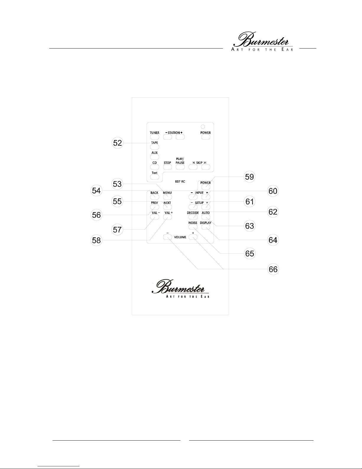
The remote control (included) is divided into two function units. The upper keypad (52) activates other
BURMESTER components such as preamplifiers, FM tuners, CD players, DVD players. Please refer to the owner’s
manual of those components for the individual functions of these keys.
The keys of the lower keypad are exclusively used for operating the surround processor and have the following
functions:
POWER The power button (59) turns the surround processor on or off.
It is necessary that the power switch (17) is in the STBY position.
INPUT The keys INPUT + and INPUT – (60) are used to successively select the inputs. This
function is equivalent to the input selection buttons (9) „INPUT +“ and „INPUT –“ on front
of the surround processor.
SETUP The keys SETUP + and SETUP – (61) are used to load one of the four possible
programmable presets. The factory preset can be found in APPENDIX A.
This function can only be accessed with the remote control.
DISPLAY The DISPLAY key (65) can be used to turn the display on or off.
If the Display Off mode is set to YES in the SETUP MENU, the display will turn dark a few
seconds after turning-on. If set to NO, the display remains on at all times. The Display Off
function will be deactivated during configurating mode.
NOISE The key NOISE (64) turns the internal noise generator for adjusting the system on or off.
AUTO By pressing the key AUTO (63), the automatic decoding of incoming audio signals is
activated. This is indicated by the illuminated AUTO DECODE LED (14) on front of the
surround processor. The received audio signals are automatically decoded depending on
the surround mode-preset of the selected input.
This function can also be activated with the AUTO decode button (13) on front of the
surround processor.
DECODE By pressing the DECODE key (62) any desired decoding of incoming audio signals is
possible. This is indicated by the DECODE LED (10) on front of the surround processor.
After activation, the desired decoding mode can be selected by repeatedly pressing the
DECODE key (62). The available modes are subject to the input signal.
If the incoming signal can be decoded by the unit, the DECODE-OK LED (12) illuminates.
If decoding in the desired mode is not possible, the DECODE-OK LED (12) remains dark
and the unit switches the outputs mute.
If the input signal changes after selection of the decoding mode, so that it cannot be
reproduced in that mode, the unit switches to automatic decoding.
This function can also be activated using the DECODE button (11) on the front of the
surround processor.
VOLUME The volume keys (65) can be used to increase (VOLUME +) or decrease (VOLUME -)
overall volume. The playback volume is indicated by the volume indicator (6). By briefly
pressing the according button, volume can be adjusted incrementally.
Volume can also be adjusted using the volume buttons (16) on front of the surround
processor.
Page 17
11
REMOTE CONTROL
Page 18

12
LOUDSPEAKER SYSTEMS AND SET-UP
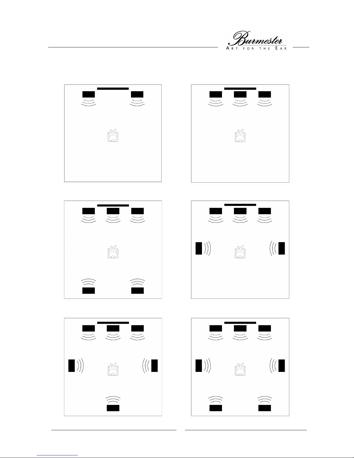
The surround processor 007 provides the option to connect up to 8 loudspeakers.
The smallest configuration involves two loudspeakers: front left , front right - this configuration is only appropriate
for STEREO reproduction.
The smallest configuration for reproduction of surround coded audio signals involves three loudspeakers: front left,
front right , center.
The largest configuration involves eight loudspeakers: front left , front right , center , subwoofer , rear left , rear
right , extended left , extended right.
NOTE: The loudspeaker systems front, center, rear and extended should have identical sound characteristics. This
is the only way that the maximum quality of surround reproduction can be achieved.
FRONT The loudspeakers front left and front right should each have the same lateral
distance from the screen.
The front speakers are obligatory for every surround system.
CENTER The center loudspeaker should be placed directly over or under the screen.
The center stabilizes the sound characteristics and supports dialog reproduction.
NOTE: Please make sure that your center loudspeaker is magnetically shielded
or that there is plenty of distance to the screen, otherwise picture quality may
suffer (even permanently) when a tube t.v. is in use.
SUBWOOFER Set-up for the subwoofer can be chosen freely, since the low frequencies can
hardly be located.
The subwoofer adds a strong foundation to the sound characteristics and
optimizes reproduction of the LFE channel.
NOTE: Please make sure during set-up that there are no objects directly near the
subwoofer which could start vibrating from reflected sound and disturb the sound
quality.
REAR The rear loudspeakers are set up with the appropiate distance left and right from
the listening position or slightly shifted sideways behind the listening position.
The rear loudspeakers support spatial sense of sound and are necessary for
spatial reproduction of surround effects.
EXTENDED The extended channel can be reproduced by one or two loudspeakers.
When using one speaker, it is set up with the appropiate distance behind the
listening position. W hen using two speakers, they are set up slightly shifted
sideways behind the listening position.
Page 19
13
LOUDSPEAKER SET-UP
2.0/2.1 set-up 3.0/3.1 set-up
typical 5.0/5.1 set-up alternative 5.0/5.1 set-up
6.0/6.1 set-up 7.0/7.1 set-up
Page 20

14
CONFIGURATION MENUS
The CONFIGURATION MENUS allow you to adjust the surround processor to your system’s needs
and your personal preferences. Each CONFIGURATION MENU is divided into menu items. The
different menu items can be adjusted individually and in any order.
There are four SETUPs for the configuration of the unit. Using the remote control keys SETUP + and
SETUP – (61) the SETUPs can be called up in reproduction mode. Any changes to an existing SETUP
are automatically saved in temporary storage after exiting the CONFIGURATION MENU, so that you
have the possibility to compare different settings without overwriting the SETUPs you generated. If you
want to keep the chosen settings permanently, you can save them using the menu item „save“ in the
GLOBAL MENU or SETUP MENU.
If you turn the unit off with the POWER switch (17), all settings are returned to the data last saved.
Changes in settings have an immediate effect upon the reproduction of the unit. We therefore
recommend adjusting the playback volume accordingly.
The CONFIGURATION MENUS are only to be accessed with the remote control keys MENU, BACK,
PREV, NEXT, VAL+ and VAL-.
The keys VOLUME+, VOLUME-, INPUT+, INPUT– and NOISE also remain active in the
CONFIGURATION MENUS.
The keys SETUP +, SETUP -, DECODE, AUTO, and DISPLAY have no function in this case.
Configuration menus are divided in the following way:
The GLOBAL MENU contains settings which are adjusted once, while keeping a constant
configuration of the entire system and speaker set-up. Settings in the GLOBAL MENU are adopted
into all four SETUPs. The menu items in the GLOBAL MENU serve as the basic configuration of the
unit and should definitely be set by an expert when installing the system.
Settings in the GLOBAL MENU can be saved with the menu item „save“. Settings which are not saved,
will be lost after the unit is turned off.
The SETUP MENU contains settings with which you can preset the surround processor to the listening
situation and your personal preferences. In order to switch back and forth easily between different
settings, you can save these in four SETUPs.
Settings in the SETUP MENU can be saved with the menu item „save“. Settings which are not saved,
will be lost after the unit is turned off.
The QUICK MENU contains settings which are adjusted during everyday use (i.e. adjusting the LFE
level during a listening session).
Adjustments which are made in the QUICK MENU, are not saved and will return to the original settings
when turning the unit off or using the keys SETUP + or SETUP –.
All settings from the QUICK MENU can also be found in the SETUP MENU. The adjusted settings are
automatically adopted into the active SETUP. If you desire to change one of the settings from the
QUICK MENU permanently, you can do this with the menu item „save“ in the SETUP MENU.
Page 21

15
CONFIGURATION MENUS
Activating Menus
In order to enter the CONFIGURATION MENUS, press the key MENU (53) .
The display will show QUICK MENU
Using the keys NEXT (55) and PREV (56), choose the desired menu.
By pressing the key MENU (53) you will reach the menu item selection level of the desired menu.
CONFIGURATION MENUS
Navigating within Menus
Once you have activated a menu, the display will show the first menu item.
Using the keys NEXT (55) and PREV (56) choose the desired menu item.
Use the key MENU (53) to select the current menu item for adjustment.
Some menu items can be adjusted without using the MENU key again.
If a menu item has an adjustable value, it will be shown on the right side of the display. This value can
be changed using the keys VAL- (57) and VAL+ (58).
Using the key BACK (54) closes the current menu item.
CONFIGURATION MENUS
Exiting Menus
By repeatedly pressing the key BACK (54) you will exit the CONFIGURATION MENUS.
The unit is now in playback mode and the display indicates the active source, the decoding mode and
the current playback volume.
Page 22

16
THE GLOBAL MENU
Contents Overview
MENU ITEM BRIEF DESCRIPTION
Speaker
Entering current number of speakers and
their size
Distance
Entering distance of each speaker from
listening position
5.1 SurroundOut
Entering which rear speaker should
reproduce surround channels
In
Assigning names, and assigning audio
input jacks and video input jacks to inputs
AnaIn
Adjusting input sensitivity of the analog
inputs
XLR Pinout
Entering pin assignment of balanced XLR
output jacks
InitialVolume
Setting initial volume of surround
processor
Save Saving personal settings in all SETUPs
Defaults Loading factory settings
Page 23

17
THE GLOBAL MENU
Speaker configuration
In this menu item, you set the speakers of your system and their size. Setting the loudspeaker
configuration is urgently necessary in order to utilize the full capacity of the unit. Information on factory
presets can be found in APPENDIX A.
There are the following loudspeaker groups: - subwoofer
- front (left/right)
- center
- rear (left/right)
- extended left
- extended right
Each speaker group (except for the subwoofer) has the following possible settings:
LARGE : The speaker group reproduces the entire frequency range, especially the
bass region below 100 Hz
SMALL : The speaker group cannot reproduce enough of the lower bass region.
NONE : The speaker group does not exist.
If the display shows ---- , the selected setting is not available.
A configuration without the speaker group front (left/right) is not possible, therefore it is only possible
to select LARGE or SMALL - NONE is not possible.
If there is no subwoofer, only the setting LARGE can be selected for the speaker group front
(left/right).
For the subwoofer, the selection can only be made between existent or not existent:
Setting YES : Subwoofer is existent
Setting NO : Subwoofer is not existent
Activate the GLOBAL MENU and select the menu item Speaker.
Press the key MENU (53).
The display will show Speaker: Subwoofer YES (instead of YES it may show NO)
By pressing the keys NEXT (55) and PREV (56), the desired speaker group is selected.
Using the keys VAL- (57) and VAL+ (58), choose the desired setting.
By pressing the key BACK (54) you will reach the menu item selection level.
The display will show Speaker:
Page 24

18
THE GLOBAL MENU
Speaker distance
In order to produce ideal sound characteristics, it is important that the sound waves of all speakers
reach the listening position at the same time. Since the distance of each speaker from the listening
position usually differs, the setting speaker distance (distance) offers the possibility to delay the
sound radiation of the closer speakers.
First, determine the distance of each system speaker to the listening position in cm and enter
these figures in the table.
NOTE: Scale factor between inch and cm is 2.54 – means: 1inch = 2.54cm
Distance
Front left __________cm
Center __________cm
Front right __________cm
Rear left __________cm
Rear right __________cm
Subwoofer __________cm
Extended left __________cm
Extended right __________cm
Activate the GLOBAL MENU and choose the menu item Distance.
Press the key MENU (53).
The display will show Distance:Front-Left: 0 (instead of 0 it may show another figure)
Using the keys NEXT (55) and PREV (56) choose the speaker which is to be set.
Using the keys VAL- (57) and VAL+ (58) choose the desired setting.
The distance can be adjusted in increments of 20 cm. Select the figure which is closest to the
one measured.
By pressing the key BACK (54) you will reach the menu item selection level.
The display will show Distance:
Page 25

19
THE GLOBAL MENU
5.1 Surround Out
When 5 channel reproduction is available, the surround channels are usually reproduced by the rear
speakers. If the system also contains extended speakers, you can choose which speakers should
reproduce the surround signals.
There are three possible settings:
REAR : The signals of the surround channels are only reproduced by the rear
speakers.
EXTENDED : The signals of the surround channels are only reproduced by the
extended speakers.
REAR+EXT : The signals of the surround channels are reproduced by the rear and the
extended speakers.
Activate the GLOBAL MENU and choose the menu item 5.1 SurroundOut.
The display will show 5.1 SurroundOut: REAR (instead of REAR another mode may
appear)
Using the keys VAL- (57) and VAL+ (58) choose the desired setting.
Page 26
20
THE GLOBAL MENU
Configurating the inputs
The surround processor can manage upto 15 logical inputs. Each logical input can be assigned a
name, an audio input on the rear of the surround processor, and a video input on the rear of the power
supply unit.
When the corresponding input is selected during reproduction mode, the assigned name appears in
the input indicator of the display, and the assigned audio input as well as the assigned video input will
be activated.
Furthermore, the surround mode can be configurated for each input (see SETUP MENU).
During configuration, the unit reproduces the signals which are adjacent to the selected inputs.
In the following menu description, the configuration of input 1 serves as an example.
Activate the GLOBAL MENU and select the menu item In.
Press the key MENU (53).
The display will show In:1 DVD : (instead of DVD another name may appear)
Using the keys NEXT (55) and PREV (56) choose the input you wish to configurate.
Press the key MENU (53).
The display will show In:1 DVD:Name: DVD (instead of DVD another name may appear)
Using the keys VAL- (57) and VAL+ (58) enter the desired name. For information on the
possible settings, please refer to the table „input names“ in APPENDIX B.
The setting ---- means that the input will not be selected during replay mode.
Press the key NEXT (55).
The display will show In:1 DVD:Audio: INP.4 (instead of INP.4 another input may appear)
Using the keys VAL- (57) and VAL+ (58) select the desired audio input. Information on the
optional settings can be found in the section „rear view of the surround processor“ in the
chapter VIEWS OF UNITS.
Press the key NEXT (55).
The display will show In:1 DVD:Video: SVID1 (instead of SVID1 another input may
appear)
Using the keys VAL- (57) and VAL+ (58) select the desired video input. Information on the
optional settings can be found in the section „rear view of the power supply unit“ in the chapter
VIEWS OF UNITS.
By pressing the key BACK (54) twice you will reach the menu item selection level.
The display will show In:
Page 27

21
THE GLOBAL MENU
Input sensitivity of the analog inputs
This menu item is used to set the input sensitivity of the analog inputs and to activate or deactivate the
automatic sensitivity control.
The analog inputs are located on the rear of the surround processor. They are marked INPUT 7 to
INPUT 9.
Before activating the menu, choose the analog input you want to set, because it is not possible to
change the inputs once you are in the menu.
While using the menu, signals may be reproduced distorted, since the automatic sensitivity control is
deactivated.
Auto settings:
You can decide if input sensitivity should be regulated automatically as soon as an overload of the
corresponding input occurs.
There are two possible settings:
YES : The sensitivity of the input is adjusted to the value which is selected with
the volume setting and is automatically reduced when an overload occurs.
NO : The sensitivity of the input is adjusted to the value which is selected with
the volume setting and is not automatically reduced when an overload
occurs.
Volume Setting:
When using auto setting NO you select the sensitivity of the input.
When using auto setting YES you select the sensitivity of the input at which the automatic control is
initiated.
There are 61 possible settings:
Setting 0 : least sensitivity
to
Setting 60 : highest sensitivity
In the following menu description, the configuration of input 7 serves as an example.
Activate the GLOBAL MENU and choose menu item AnaIn.
Press the key MENU (53).
The display will show AnaIn:Inp.7:
Using the keys NEXT (55) and PREV (56) choose the input to be configured.
Press the key MENU (53).
The display will show AnaIn:Inp.7:Auto: YES (instead of YES it may show NO)
Using the keys VAL- (57) and VAL+ (58) select the desired setting.
Press the key NEXT (55).
The display will show AnaIn:Inp.7:Volume: 50 (instead of 50 another value may appear)
Using the keys VAL- (57) and VAL+ (58) select the desired setting.
By pressing the key BACK (54) twice you will reach the menu item selection level.
The display will show AnaIn:
Page 28

22
THE GLOBAL MENU
Pin assignment of the XLR outputs
Not all audio components with XLR jacks have the same pin assignment as BURMESTER
components.
In this menu item you can attune the pin assignment of the XLR output jacks to the connected power
amps or active speakers. Please check beforehand which pin assignment your connected units have.
The setting of the pin assignment is valid for all XLR output jacks of the surround processor. If
individual power amps or active speakers have a different pin assignment than the one set up, you
need to employ accordingly manufactured connecting cables. Please contact your specialized dealer.
There are two possible settings:
BURMESTER : Pin1 = GND Pin2 = negative Pin3 = positive
IEC : Pin1 = GND Pin2 = positive Pin3 = negative
Activate the GLOBAL MENU and select the menu item XLR Pinout.
The display will show XLR Pinout: BURMESTER (instead of BURMESTER it may show
IEC)
Using the keys VAL- (57) and VAL+ (58) select the desired setting.
THE GLOBAL MENU
Initial volume
With this function you can set the initial volume of the unit. When using the setting LAST, the unit
saves the volume which was last used before shutting down. For reasons of safety, this value is
limited to 40.
You can also specify a set value for initial volume, for example 23. This value is also limited to 40 for
safety.
Activate the GLOBAL MENU and select the menu item InitialVolume.
The display will show InitialVolume: LAST (instead of LAST a different value may
appear)
Using the keys VAL- (57) and VAL+ (58) select the desired setting.
Page 29
23
THE GLOBAL MENU
Saving
Any changes made within the GLOBAL MENU are automatically saved in temporary storage after
exiting the the menu, and remain intact until shutting off the unit. If you want to keep the chosen
settings after shutting down, you need to save them using the SAVE function.
Activate the GLOBAL MENU and select the menu item Save.
Press the key MENU (53).
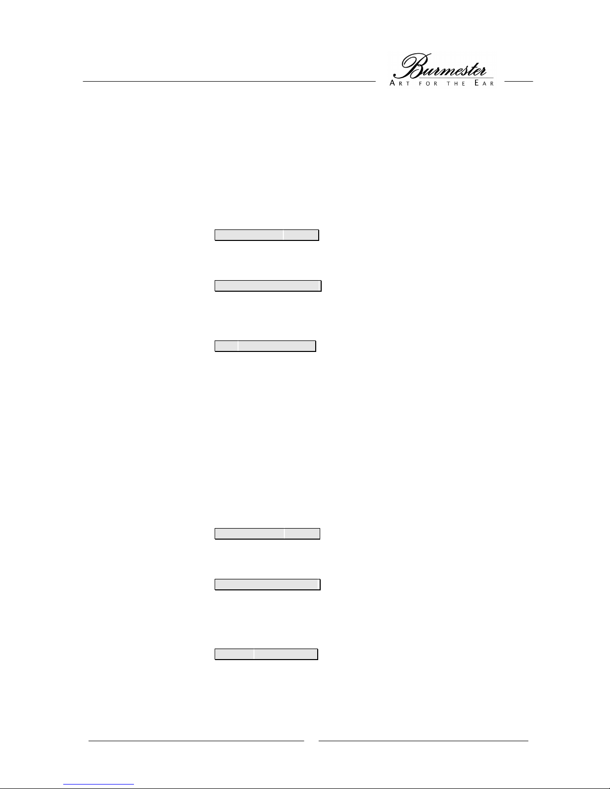
The display will show Save:GLOBAL ?
Press the key MENU (53).
The display will show Save:GLOBAL ? saved
The settings have been saved.
By pressing the key BACK (54) twice you will reach the menu item selection level.
The display will show Save:
THE GLOBAL MENU
Factory settings
Changes settings within the GLOBAL MENU back to factory settings (defaults).
Activate the GLOBAL MENU and select the menu item Defaults.
Press the key MENU (53).
The display will show Defaults:Reset ?
Press the key MENU (53).
The display will show Defaults:Reset ? ok
The factory settings have now been saved in temporary storage. If you want to keep the factory
settings after shutting down, you need to save them using the SAVE function.
By pressing the key BACK (54) twice you will reach the menu item selection level.
The display will show Defaults:
Page 30

24
THE SETUP MENU
Overview
MENU ITEMS BRIEF DESCRIPTION
Level
Volume equalization of all speakers with
reference to listening position
Level LFE Volume of low bass range
Dynamic Range
Setting dynamic range of sound
reproduction
SrndMode Assigning surround to inputs
Display Off Mode
Determines if display remains lit or dark
after operating unit
Dolby D Dual Mono Mode
Selecting channel during reproduction of
double mono signals (two-channel)
DTS NeoMode
Setting playback mode for stereo
signals
Dolby PLII Mode
Setting playback mode for stereo
signals and encoded two-channel
signals
Dolby PLII Panorama
Expansion of front stereo sound
impression to surround speakers
Dolby PLII Center Width
Shifting center output signal to the front
channels
Dolby PLII Dimension
Influencing sound impression in the
“front-rear-perspective“
Save Saving personal settings in SETUP
Defaults Loading factory settings
Page 31

25
THE SETUP MENU
Speaker level
In order to determine the optimal volume relationship of the connected loudspeakers, you should sit in
your listening spot. The goal is to adjust the playback volume of all speakers in such a way that the
signal of all speakers is heard equally loud at the chosen listening position.
The unit offers a noise generator to aid in this setting, which is activated and deactivated with the key
NOISE (64). The playback volume is automatically set to 20 upon activation and deactivation of the
noise generator in order to avoid overload or damage to your ears and/or speakers.
An exact adjustment may take some time. You can keep changing the setting for each speaker until
you have found the optimal tuning.
The tuning span ranges from -12 to +12 in increments of 1. The values are in dB.
Activate the SETUP MENU and select menu item Level.
Press the key MENU (53).
The display will show Level:Front-Left: 0 (instead of 0 another value may appear)
If you wish to use the noise generator for your adjustment, press the key NOISE (64).
Increase the playback volume by pressing the key VOLUME + (65), until you have reached a
comfortable volume for yourself.
Using the keys VAL- (57) and VAL+ (58) select the desired settings.
Using the keys NEXT (55) and PREV (56) you select the speakers.
By pressing the key BACK (54) twice you will reach the menu item selection level.
The display will show Level:
THE SETUP MENU
Level LFE
If you find the reproductiuon of the lower bass range too loud, you can reduce volume of the low bass
frequencies.
The tuning span ranges from 0 to -12 in increments of 1. The values are in dB.
Activate the SETUP MENU and select the menu item Level LFE.
The display will show Level LFE: 0 (instead of 0 another value may appear)
Using the keys VAL- (57) and VAL+ (58) select the desired settings.
Page 32

26
THE SETUP MENU
Dynamic Range
Dynamic range describes the volume relationship among the soft and loud passages of sound
reproduction.
There are three possible settings:
LARGE: With a large dynamic range, soft passages (whispering) are considerably
softer than the middle playback volume, and the loud passges
(explosions) are very loud. The setting LARGE almost corresponds to
playback in movie theaters.
Select this setting if you are able to set general volume at a level where
soft passages are still audible and loud passages are not distorted.
STD: The setting STD corresponds to the common setting for playback at
home.
Select this setting, when there are no reaons for choosing LARGE or
SMALL.
SMALL: With a small dynamic range, the soft passages are reproduced only
slightly less softly than the middle playback volume, the loud passages
only slightly louder.
Select the setting SMALL, when maximum playback volume should not
exceed a certain level, and soft passages should remain audible (late
night playback).
Activate the SETUP MENU and select the menu item Dynamic Range.
The display will show Dynamic Range: STD. (instead of STD. another mode may
appear)
Using the keys VAL- (57) and VAL+ (58) select the desired setting.
Page 33

27
THE SETUP MENU
Surround mode of the inputs
Decoding the incoming signals depends on the setting of the surround mode. A surround mode is
assigned to each logical input.
There are four possible settings:
STEREO : All incoming signals are mixed down to the front channels (2channel
downmix).
SRND : Incoming multi-channel signals are reproduced as multi-channel signals,
stereo signals are reproduced with Dolby Pro Logic or Dolby Pro Logic II.
AUTO : Like SRND setting, except that compressed 2-channel signals, which are
specifically not marked with surround code, are only reproduced via the
front speakers.
DTS : All incoming signals are decoded using DTS. Non-DTS coded signals are
not reproduced.
If forced decoding is activated during reproduction, this function has precedence over surround mode
settings.
Activate the SETUP MENU and select the menu item SrndMode.
The display will show SrndMode:
Press the key MENU (53).
The display will show SrndMode:DVD : AUTO (instead of AUTO another mode may
appear)
Using the keys NEXT (55) and PREV (56) select the input to be set.
Using the keys VAL- (57) and VAL+ (58) select the desired settings.
By pressing the key BACK (54) twice you will reach the menu item selection level.
The display will show SrndMode:
THE SETUP MENU
Display Off Mode
If the illuminated display window is considered a distraction during reproduction, the unit may be
programmed in such a way that the display will switch off automatically a few seconds after the last
change of control settings (DisplayOffMode: YES). Each time a setting is changed, the display will
illuminate and then turn off again after a few seconds.
If you simply want to check the current status without making a change (i.e. change source or
volume…), press the key DISPLAY (63) on the remote control. The display will iluminate for a few
seconds and will return to Off Mode automatically. During menu activity the display remains on
regardless of the selected mode.
There are two possible settings:
YES : Display Off Mode is activated
NO : Display remains on
Activate the SETUP MENU and select the menu item DisplayOffMode.
The display will show DisplayOffMode: NO (instead of NO it may show YES)
Using the keys VAL- (57) and VAL+ (58) select the desired settings.
Page 34

28
THE SETUP MENU
Dolby Digital Dual Mono Mode
Dolby digital sources can supply double mono signals, where both channels contain different
information, i.e. in different languages (two-channel sound). Using the setting of the Dolby Digital Dual
Mode you can select how these are reproduced.
There are four possible settings:
STEREO : left channel in left front speaker, right channel in right front speaker
MONO L : left channel in both front speakers
MONO R : right channel in both front speakers
MONO LR : both channels in both speakers
Activate the SETUP MENU and select the menu item DolbyD DualMode.
The display will show DolbyD DualMode:STEREO (instead of STEREO another mode may
appear)
Using the keys VAL- (57) and VAL+ (58) select the desired settings.
THE SETUP MENU
DTS Neo Mode
DTS NEO 6.1 is a process for reproducing stereo signals in multi-channel fashion. You can choose
here how reproduction is to occur.
There are five possible settings:
5CH MUSIC : Reproduction via front, center and rear speakers -
preferable for music
6CH MUSIC : Reproduction via front, center, rear and extended speakers -
preferable for music
3CH CINEMA: Reproduction via front and center speakers -
preferable for movies
5CH CINEMA: Reproduction via front, center and rear speakers -
preferable for movies
6CH CINEMA: Reproduction via front, center, rear and extended speakers -
preferable for movies
Activate the SETUP MENU and select the menu item DTS NeoMode.
The display will show DTS NeoMode: 5CH MUSIC (may be different than 5CH MUSIC)
Using the keys VAL- (57) and VAL+ (58) select the desired settings.
THE SETUP MENU
Pro Logic II Mode
Page 35

29
Dolby Pro Logic is a procedure for multi-channel reproduction of stereo signals and surround encoded
two-channel signals. You can select here, how playback is to occur.
There are three possible settings:
MUSIC : Select the setting MUSIC for music playback with stereo signals as well as
surround encoded two-channel signals.
MOVIE : Select the setting MOVIE for movie playback with stereo signals as well as
surround encoded two-channel signals.
PRO LOGIC : Select the setting PRO LOGIC if the playback quality of the other modes is
not satisfactory
Activate the SETUP MENU and select the menu item PL II Mode: .
The display will show PL II Mode: MUSIC (instead of MUSIC another mode may appear)
Using the keys VAL- (57) and VAL+ (58) select the desired settings.
THE SETUP MENU
Dolby Pro Logic II Panorama
This mode extends the front stereo sound characteristics to the surround speakers, in order to create
an expanded spatial sound impression.
There are two possible settings:
OFF : The panorama mode is off.
ON : The panorama mode is activated.
The setting in this menu item only has an effect upon the sound characteristics if the menu item „Dolby
Pro Logic II Mode“ in the SETUP MENU is set to MUSIC.
Activate the SETUP MENU and select the menu item PL II Panorama.
The display will show PL II Panorama: ON (instead of ON it may show OFF)
Using the keys VAL- (57) and VAL+ (58) select the desired settings.
THE SETUP MENU
Dolby Pro Logic II Center Width
Page 36

30
With this mode you can shift the center output signal incrementally to the two front channels.
There are eight possible settings:
Setting 0 : The center output signal remains unchanged.
to
Setting 7 : The center output signal is completely transfered to the front channels -
the center speaker reproduces no signal.
The setting in this menu item only has an effect upon the sound characteristics if the menu item „Dolby
Pro Logic II Mode“ in the SETUP MENU is set to MUSIC.
Activate the SETUP MENU and select the menu item PL II CenterWidth.
The display will show PL II CenterWidth: 0 (instead of 0 another value may appear)
Using the keys VAL- (57) and VAL+ (58) select the desired settings.
THE SETUP MENU
Dolby Pro Logic II Dimension
With this mode you can affect the sound impression in the „front-rear-perspective“.
There are seven possible settings:
Setting 0 : maximum surround effect
to
Setting 6 : least surround effect
with
Setting 3 : neutral
The setting in this menu item only has an effect upon the sound characteristics if the menu item „Dolby
Pro Logic II Mode“ in the SETUP MENU is set to MUSIC.
Activate the SETUP MENU and select menu item PLII Dimension.
The display will show PLII Dimension: 3 (instead of 3 another value may appear)
Page 37
31
THE SETUP MENU
Saving
Any changes made within an existing SETUP are automatically saved in temporary storage after
exiting the the SETUP menu, and remain intact until shutting off the unit. If you want to keep the
selected settings after shutting down, you need to save them using the SAVE function.
Activate the SETUP MENU and select the menu item Save.
Press the key MENU (53).
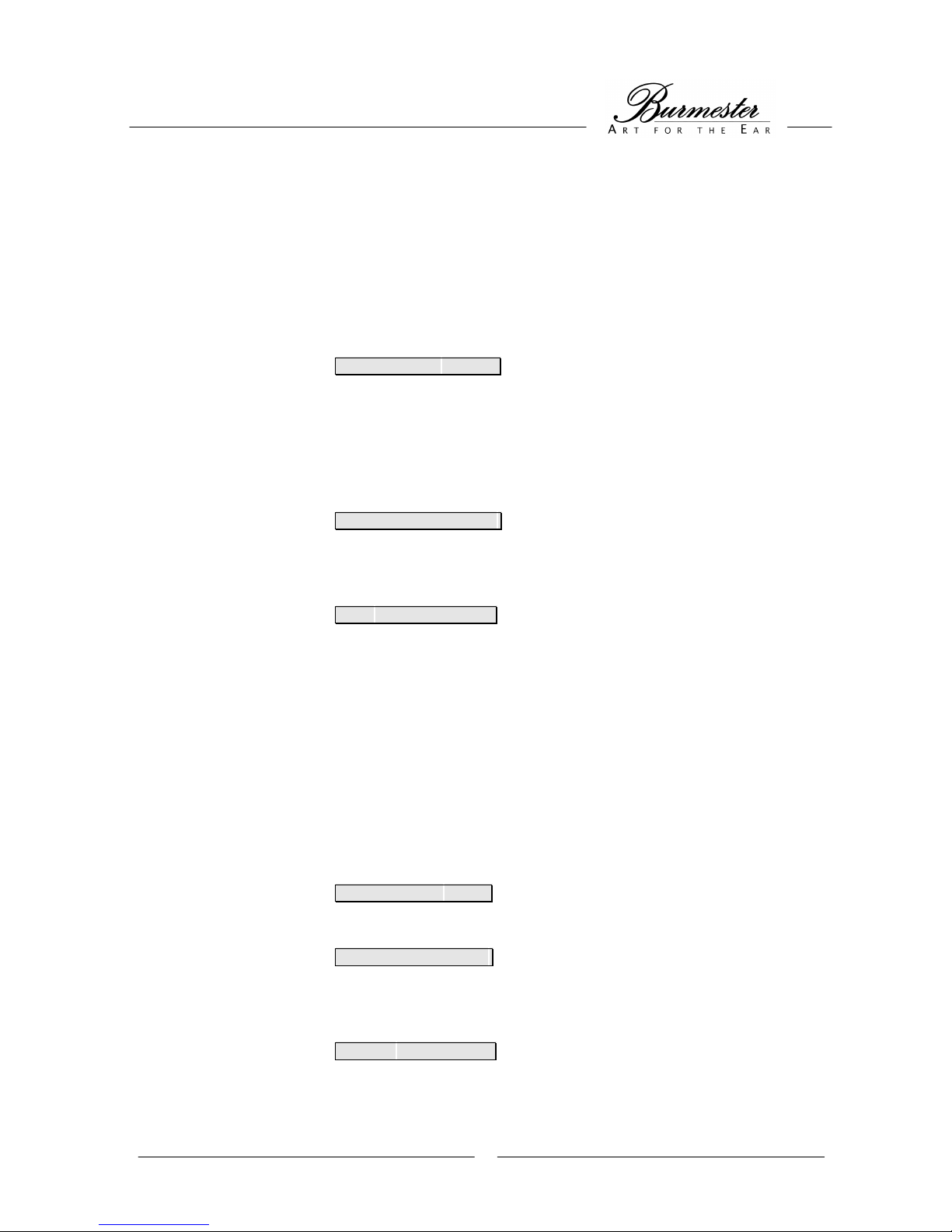
The display will show Save:SETUP 1 ?
The display will always show the SETUP which was active upon activating the menu (see
SETUP LEDs).
Using the keys NEXT (55) and PREV (56), the new settings can also be written into another
SETUP.
Press the key MENU (53).
The display will show Save:SETUP 1 ? saved
The settings have been saved and will remain intact after shuttung off the unit.
By pressing the key BACK (54) twice you will reach the menu item selection level.
The display will show Save:
THE SETUP MENU
Factory settings
This menu item will change the settings of the selected SETUP to factory settings.
Activate the SETUP MENU and select the menu item Defaults.
Press the key MENU (53).
The display will show Defaults:Reset ?
If you want to load factory settings, press MENU (53) again.
The display will show Defaults:Reset ? ok
The factory settings have now been saved in temporary storage of the selected SETUP.
By pressing the key BACK (54) twice you will reach the menu item selection level.
The display will show Defaults:
Page 38

32
THE QUICK MENU
Overview
MENU ITEM BRIEF DESCRIPTION
Level LFE: Volume equalization of the subwoofer
Dynamic Range:
Setting dynamic range of sound
reproduction
Dolby D Dual Mono Mode:
Selecting channel during reproduction of
double mono signals (two-channel)
DTS NeoMode: Setting playback mode for stereo signals
Dolby PLII Mode:
Setting playback mode for stereo signals
and encoded two-channel signals
A detailed description of menu items in the QUICK MENU can be found in the SETUP MENU.
If you would like to save settings made in the QUICK MENU, activate the menu item SAVE in the
SETUP MENU.
Page 39
33
APPENDIX A
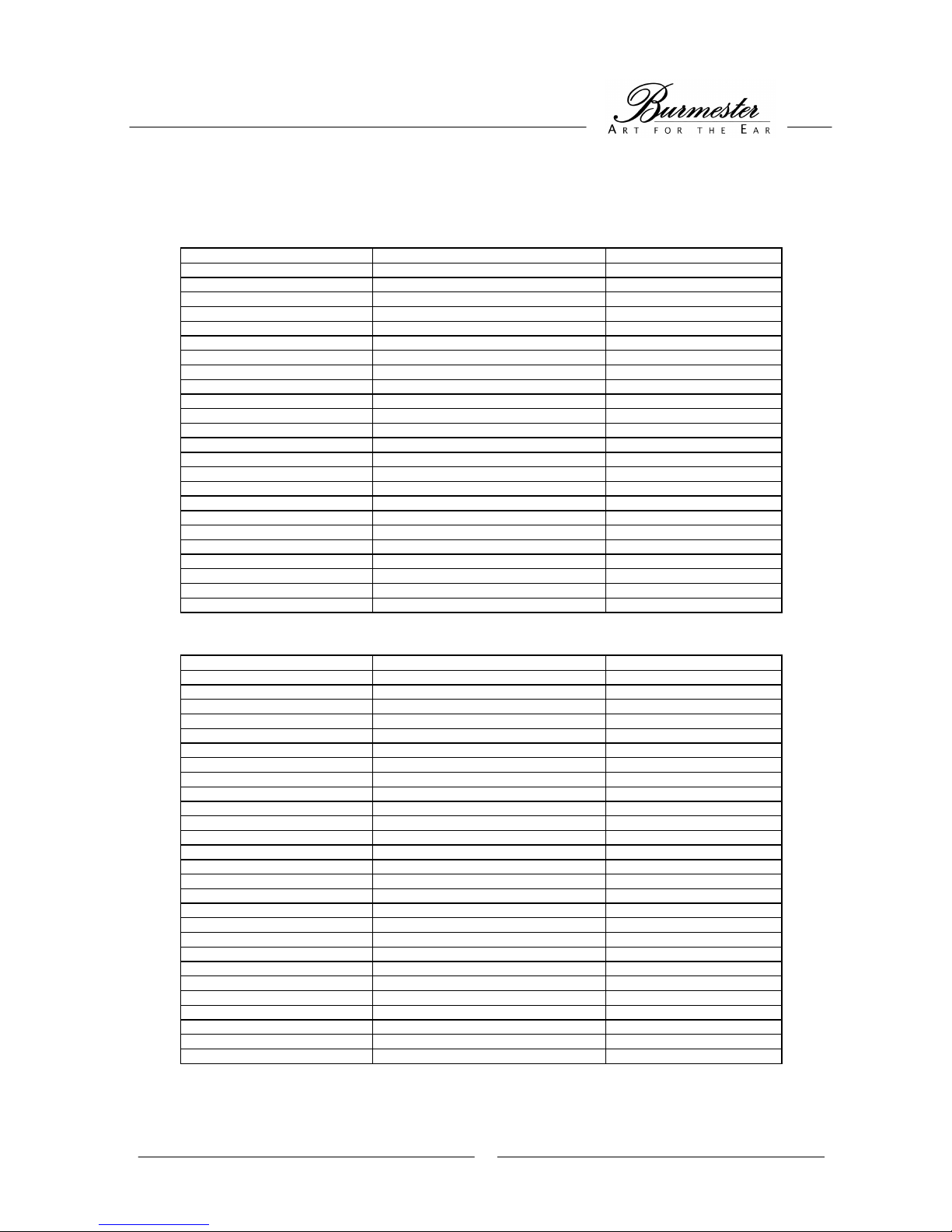
Factory settings
GLOBAL MENU
MENU ITEM SELECTION DEFAULTS
Speaker Subwoofer YES
Front LARGE
Center LARGE
Rear LARGE
Extended links NONE
Extended rechts NONE
Distance alle Lautsprecher 0
5.1 Surround Out REAR
In INPUT 1: name / audio / video DVD / INP.4 / SVID1
INPUT 2: name / audio / video TV / INP.1 / SVID2
INPUT 3: name / audio / video VCR / INP.7 / SVID3
INPUT 4: name / audio / video CD / INP.5 / OFF
INPUT 5: name / audio / video TUN / INP.8 / OFF
INPUT 6: name / audio / video TAPE / INP.9 / OFF
Ana In Ana 1 bis Ana 3: Auto / Level YES / 50
XLR Pinout BURMESTER
Initial Volume 10
SETUP MENU
MENU ITEM SELECTION DEFAULTS
Level alle Lautsprecher 0
Level LFE 0
Dynamic Range STD.
Surround Mode INPUT 1: AUTO
INPUT 2: SRND
INPUT 3: SRND
INPUT 4: STEREO
INPUT 5: STEREO
INPUT 6: STEREO
Display Off Mode NO
Dolby D Dual MonoMode STEREO
DTS Neo Mode 5CH CINEMA
Pro Logic II Mode MOVIE
Pro Logic II Panorama OFF
Pro Logic II CenterWidth 0
Pro Logic II Dimension 4
Page 40

34
APPENDIX B
Input names
DVD DVD1 DVD2 DVD3
VCR VCR1 VCR2 VCR3
TV TV1 TV2 TV3
DVB DVB1 DVB2 DVB3
LD LD1 LD2 LD3
CD CD1 CD2 CD3
TUN TUN1 TUN2 TUN3
TAPE TP1 TP2 TP3
DAT DAT1 DAT2 DAT3
PHO PHO1 PHO2 PHO3
AUX AUX1 AUX2 AUX3
PC PC1 PC2 PC3
Page 41

35
APPENDIX C
Facts about Surround
GENERAL
The technical advances of the last few years have resulted in a marked enhancement in the music playback sector,
especially regarding clarity, precision and performance of the products. However, normal stereo systems reach their
natural limits during playback of atmospherical and surround sound.
In order to overcome these weak spots, the two channels (stereo) of normal playback systems were expanded using
various effect channels.
The film industry in particular was keen on supporting this development and started installing new surround sound
systems in cinemas. Eventually, these systems found their way into living rooms all over the world.
DOLBY SURROUND / DOLBY PRO LOGIC
The DOLBY SURROUND system operates on an analog basis.
The further development of the DOLBY SURROUND system is DOLBY PRO LOGIC.
This system employs an analog matrix codification to add information for a center and surround channel to the two
stereo channels.
In this method, the rear surround channel is limited to a frequency range between 100Hz and 7kHz.
DOLBY PRO LOGIC II
In comparison to the DOLBY PRO LOGIC system, the DOLBY PRO LOGIC II system provides two effect channels
without limitation of the frequency range.
This results in a great quality enhancement as oppposed to DOLBY PRO LOGIC .
DOLBY DIGITAL (Dolby Surround AC3)
DOLBY DIGITAL is a digital multi channel format developed by the Dolby Laboratories. This system operates on a
completely digital basis and is not dependent on a specific speaker configuration. AC3 (the name of this audio
format) can work as a stereo format (2.0) or can support a subwoofer (2.1). However, 3.0, 4.0 or 4.1 is also possible.
The most common version is 5.1, a full-blown surround system with two discreet effect channels in rear, one center
and the subwoofer channel. Contrary to the analog DOLBY PRO LOGIC format, all channels except the subwoofer
channel reproduce the full range of frequencies.
DOLBY DIGITAL EX
DOLBY DIGITAL EX is an expansion of the DOLBY DIGITAL audio format and produces six playback channels
without frequency limitations from a 5.1 channel source. This is realized by a matrix codification of the effect
channels and additionally supplies a third full effect channel (EX = extended) from the two original channels.
DTS
DTS is a multi channel digital signal format developed by DIGITAL THEATER SYSTEMS. Compared to DOLBY
DIGITAL, DTS operates with a higher transfer rate. This allows for either a lower data compression or also an
expansion of effect channels up to seven channels, corresponding to 6.1.
DTS-ES
The DTS-ES system (ES = extended sound) markedly improves the 360 degree surround effect and the spatial
impression by utilizing expanded surround signals.
This is achieved with a discreet recording of all playback channels (DTS-ES DISCRETE) or a matrix codification of
the effect channels (DTS-ES MATRIX).
DTS NEO
This system generates a high quality 6.1 channel surround reproduction from a matrix coded two-channel signal.
 Loading...