

Page 1
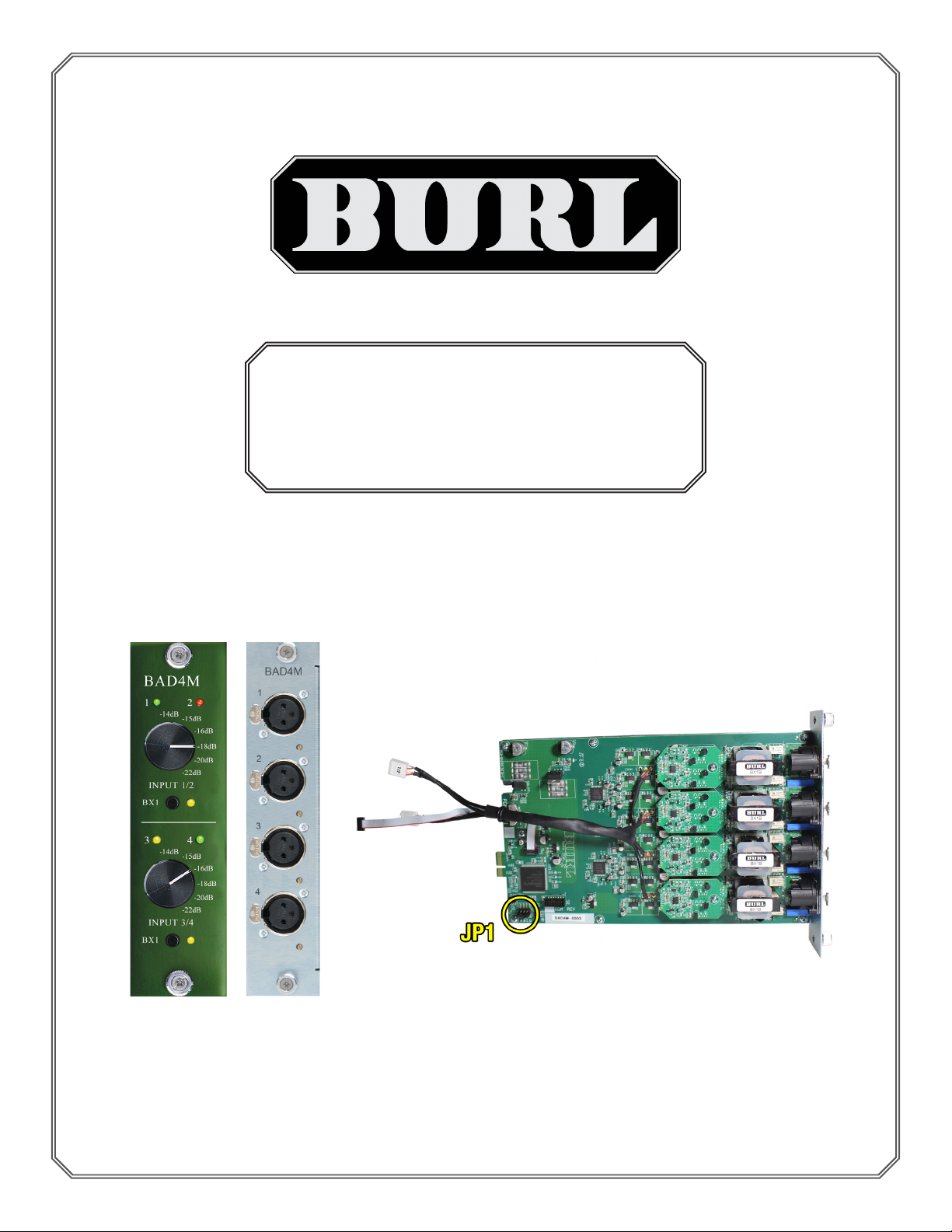
BAD4M
DAUGHTER CARD
Quick Start Guide
REGISTER YOUR PRODUCT TO ACTIVATE WARRANTY
www.burlaudio.com/register
Revision A November 7, 2019
Page 2
Important information regarding BAD4M latency:
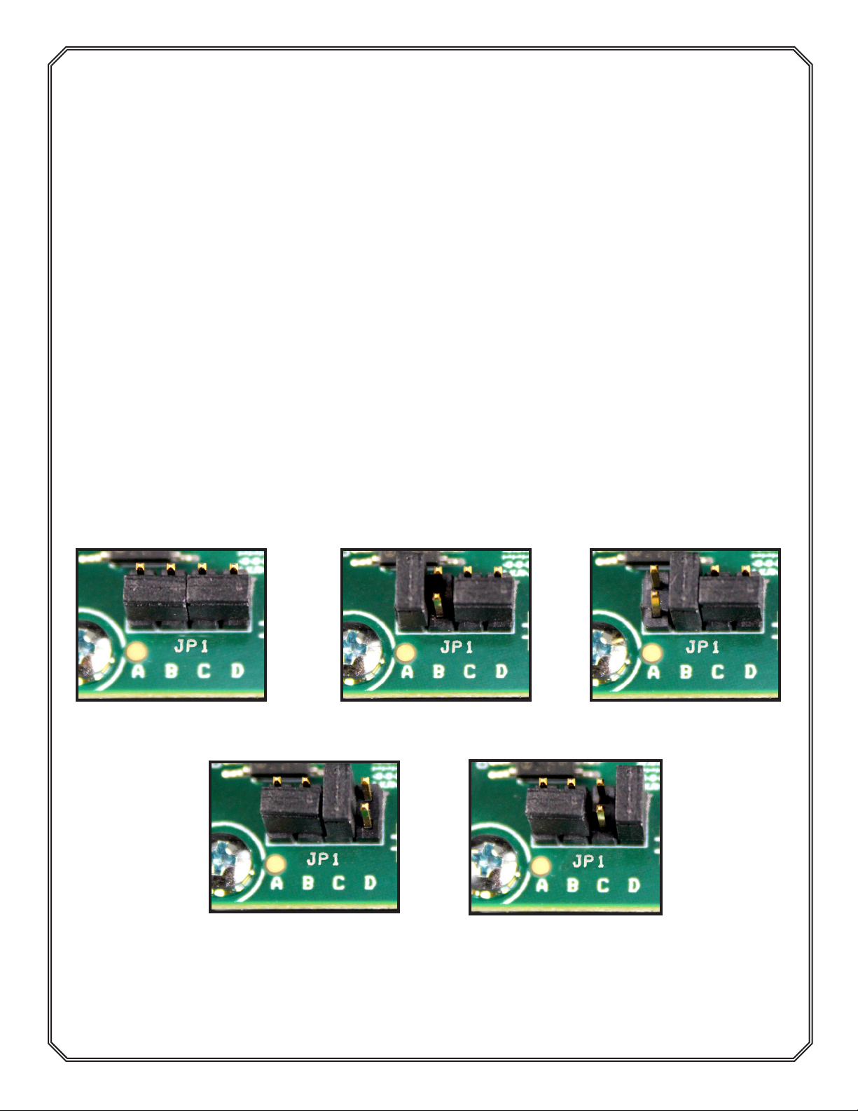
The BAD4M uses jumpers on “JP1” (as shown on cover) to adjust 2 variables: ADC
lter selection, high pass lter, and AVID HDIO delay matching.
Jumper Settings for “JP1”
Jumper A - ADC Filter Setting:
In default mode with no jumpers set, the BAD4M uses the short delay lter
with the classic “Burl Sound”. (Image 1) A jumper on “A” will switch to the long
delay lter, with longer latency and a more forward mid-range. (Image 2)
Jumper B - Avid Delay Matching:
Setting a jumper on “B” will increase latency to match the output delay of an
Avid HDIO. This is for short lter only. (Image 3)
Jumper C - BAD4 Delay Matching:
Setting a jumper on “C” will match the delay of the BAD4 input daughter card.
This will work with both short and long lters. (Image 4)
Jumper D: High-pass Filter Bypass:
Setting a jumper on “D” will bypass the high-pass lter. (Image 5) (Not recom-
mended)
Image 1: Default Jumper
Settings - No jumper set.
Image 4: BAD4 Delay
Matching - Jumper is set to
“C”.
Image 2: ADC Filter Setting - Jumper is set to “A”.
Image 5: High-pass Filter
Bypass - Jumper is set to
“D”. Not recommended.
1
Image 3: Avid Delay
Matching - Jumper is set to
“B”.
Page 3
Installing B80 Mothership Daughter Cards
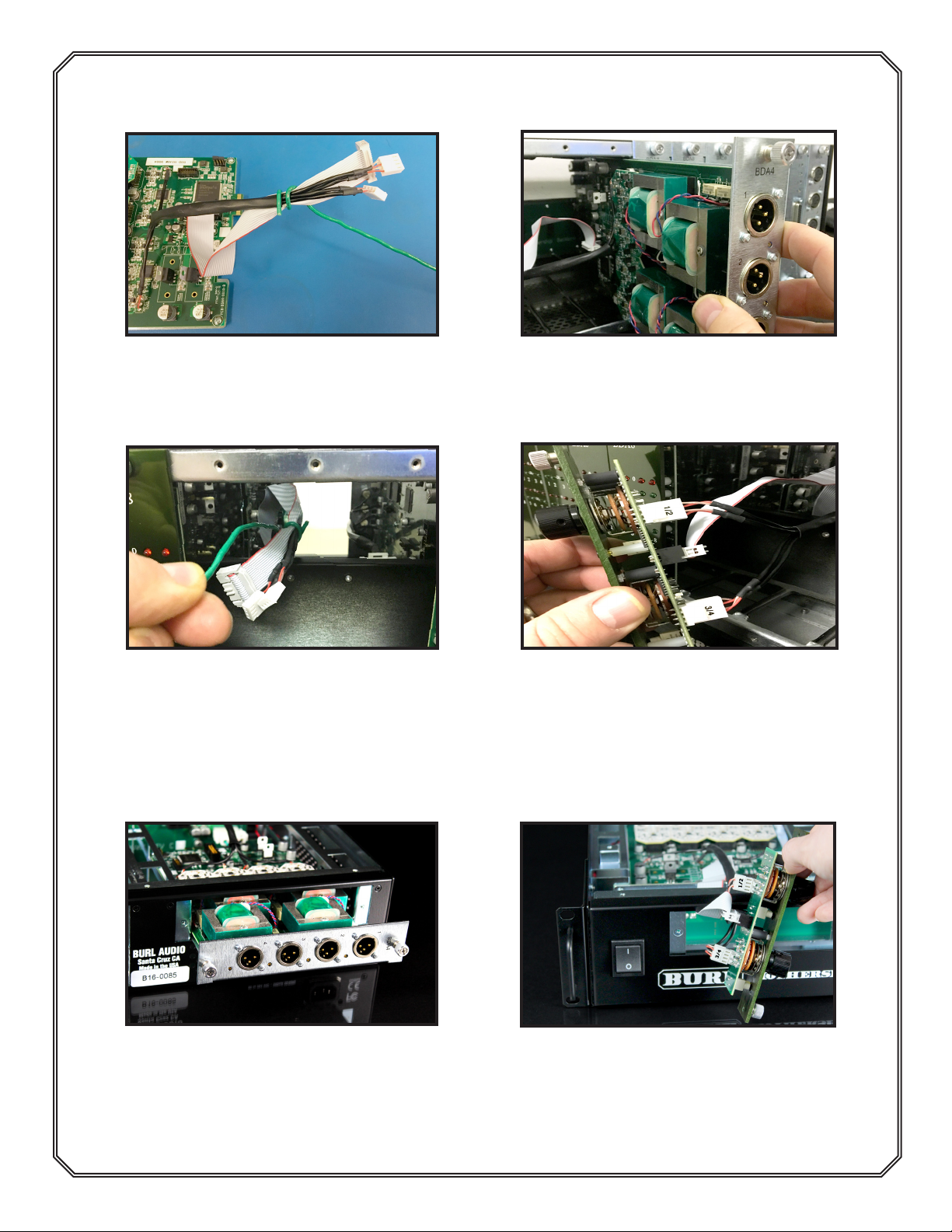
*NOTE- See B80 Mothership Quick Start Guide for more information
Image 5: Use the provided solid core
wire to wrap around the cables and pass
through from the rear of the chassis to
the front.
Image 7: Pull the cables towards the
front of the unit.
Installing B16 Mothership Daughter Cards
*NOTE- See B16 Mothership Quick Start Guide for more information
Image 6: When installing the BAD4M
into the B80 Chassis, make sure the
metal Daughter Card backplate (not the
PCB) is inserted into the card guides.
(BDA4M shown here)
Image 8: Attach the 4-pin connectors
(1/2 is on the top, 3/4 is on the bottom)
and the ribbon cable to the front panel.
Attach the front panel to the chassis us-
ing two thumb screws.
Image 9: With the B16 cover removed,
install the BAD4M into the card guides as
shown (BDA4M shown here). Make sure
the metal Daughter Card backplate, not
PCB, is inserted into the card guides.
Image 10: Pull the cables through to the
front of the chassis. Attach the 4-pin
connectors (1/2 is on the left, 3/4 is on
the right) and the ribbon cable to the
front panel. Attach the front panel to the
chassis using two thumb screws.
2
Page 4
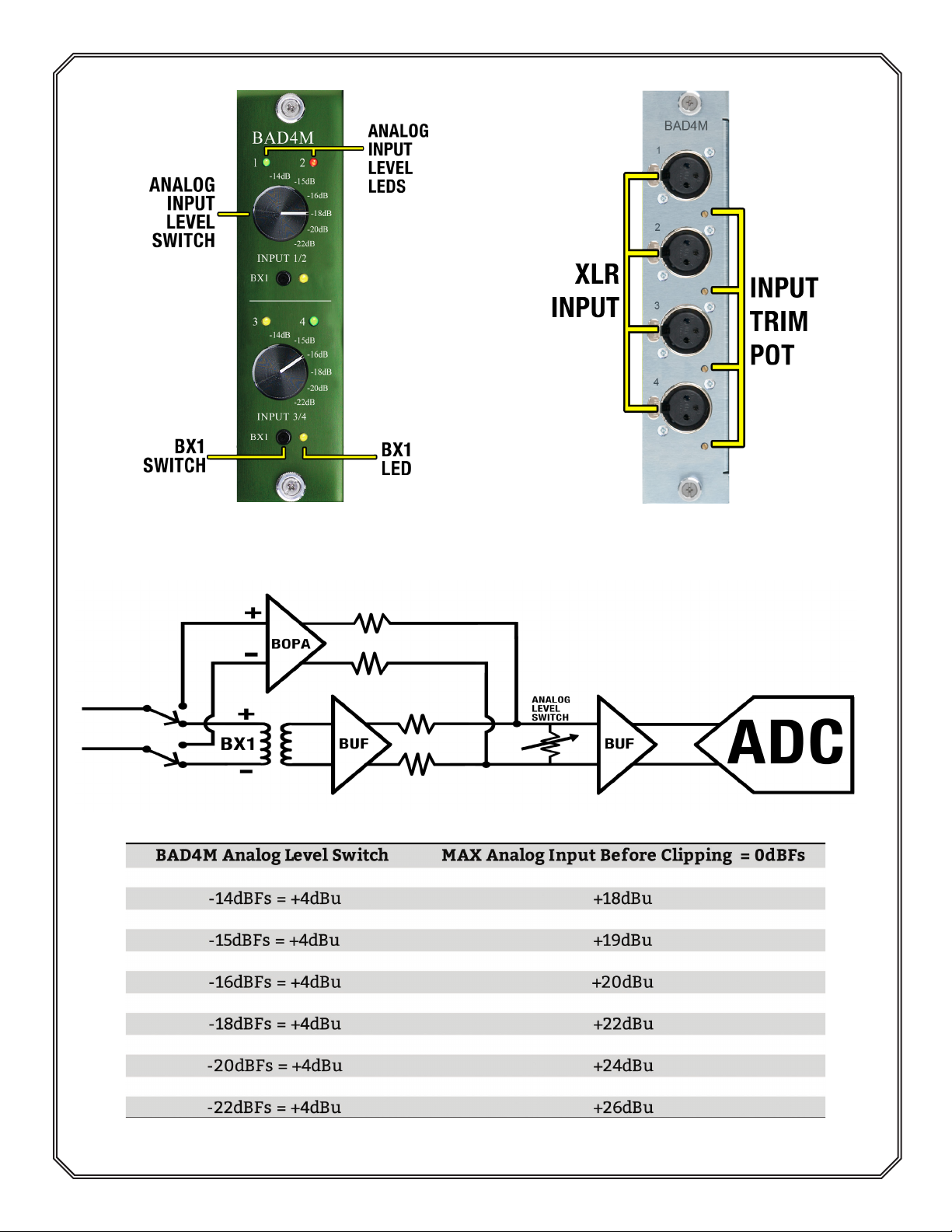
Front Panel: Rear Panel:
Image 11: BAD4M Front Panel Image 12: BAD4M Rear Panel
BAD4M Analog Input Switch and Level Attenuation
See the table below for maximum analog input at each level setting:
3
Page 5
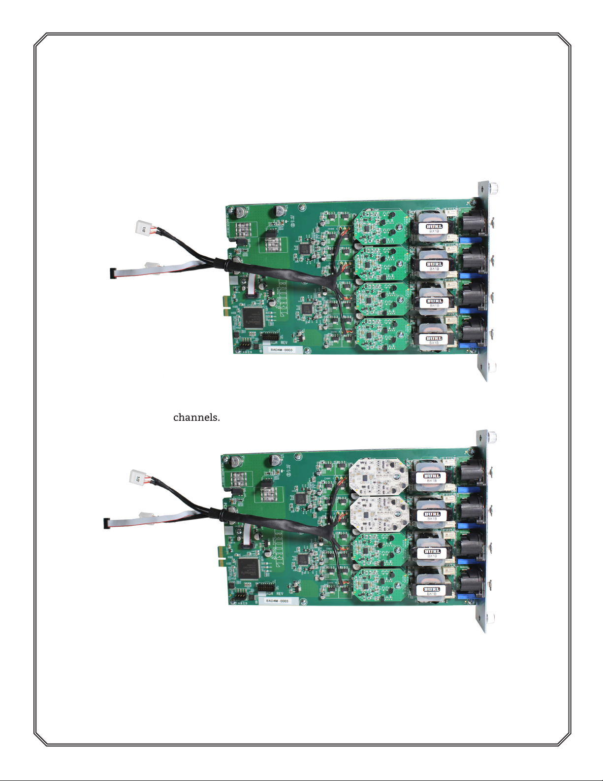
BAD4M Op-amp Conguration
The BAD4M Daughter Card can be customized with four channels of the BOPA14,
four channels of the BOPA11, or two channels of each op-amp.
The BOPA11 is ideal for mastering, with maximum clarity, detail, and minimal distortion. The BOPA14, which was initially designed for the BDA8, has a slightly more
pleasing tone and is preferred for mix down.
Image 13: BAD4M-1414, utilizing BOPA14’s on all
channels.
Image 14: BAD4M-1114, utilizing BOPA11 on channels 1/2, and BOPA14 on channels 3/4.
 Loading...