

Page 1
Type 8691
Control Head
Steuerkopf
Tête de commande
Operating Instructions
Bedienungsanleitung
Manuel d‘utilisation
Page 2

We reserve the right to make technical changes without notice.
Technische Änderungen vorbehalten.
Sous réserve de modifications techniques.
© Bürker t Werke GmbH & Co.KG, 20 - 2017
Operating Instructions 1706/_(8(1_0080 / Original DE
Page 3

Type 8691
Control head Type 8691
Table of ConTenTs
1 OPERATING INSTRUCTIONS ........................................................................................................................................................7
1.1 Symbols ......................................................................................................................................................................................7
1.2 Definition of term / abbreviation ...................................................................................................................................7
2 AUTHORIZED USE .............................................................................................................................................................................8
2.1 Restrictions ...............................................................................................................................................................................8
3 BASIC SAFETY INSTRUCTIONS .................................................................................................................................................9
4 GENERAL INFORMATION .............................................................................................................................................................10
4.1 Contact address ..................................................................................................................................................................10
4.2 Warranty ...................................................................................................................................................................................10
4.3 Trademarks ............................................................................................................................................................................10
4.4 Information on the internet ............................................................................................................................................10
5 SYSTEM DESCRIPTION ................................................................................................................................................................11
5.1 Configuration and function ............................................................................................................................................11
5.1.1 Control head for integrated installation on the 21xx series ......................................................11
5.1.2 Model for control of process valves belonging to the 20xx series ..........................................12
6 TECHNICAL DATA .............................................................................................................................................................................13
6.1 Conformity ..............................................................................................................................................................................13
6.2 Standards ................................................................................................................................................................................13
6.3 Licenses ...................................................................................................................................................................................13
6.4 Operating conditions ........................................................................................................................................................13
6.5 Mechanical data ...................................................................................................................................................................13
6.6 Type labels ..............................................................................................................................................................................14
6.6.1 Type label standard ............................................................................................................................14
6.6.2 UL Type label .......................................................................................................................................14
6.6.3 UL additional label ..............................................................................................................................14
6.7 Pneumatic data ....................................................................................................................................................................15
English
english
3
Page 4

Type 8691
6.8 Electrical data .......................................................................................................................................................................15
6.8.1 Electrical data without bus control 24 V DC ...............................................................................15
6.8.2 Electrical data with AS-Interface bus control ..............................................................................15
6.8.3 Electrical data with DeviceNet bus control ..................................................................................16
7 INSTALLATION ...................................................................................................................................................................................17
7.1 Safety instructions .............................................................................................................................................................17
7.2 Installing the control head Type 8691 on process valves belonging to series 21xx ......................17
7.3 Installing the control head Type 8691 on process valves belonging to series 20xx ......................21
7.4 Rotating the actuator module ......................................................................................................................................24
7.5 Rotating the control head for process valves belonging to series 20xx ..............................................26
8 PNEUMATIC INSTALLATION .......................................................................................................................................................27
9 ELECTRICAL INSTALLATION 24 V DC ...................................................................................................................................28
9.1 Safety instructions .............................................................................................................................................................28
9.2 Electrical installation with cable gland ....................................................................................................................28
9.3 Electrical installation with circular plug-in connector .....................................................................................30
9.4 Teach function (calibrating the end positions) ...................................................................................................30
9.5 Display elements 24 V DC .............................................................................................................................................32
9.5.1 LED status display..............................................................................................................................32
9.5.2 Device status display - assignment of the Top LEDs ................................................................33
9.5.3 Change assignment of the Top LEDs (device status) ...............................................................34
10 AS-INTERFACE INSTALLATION ................................................................................................................................................36
10.1 AS-Interface connection .................................................................................................................................................36
10.2 Technical data for AS-Interface PCBs .....................................................................................................................36
10.3 Programming data ..............................................................................................................................................................36
10.4 Electrical installation AS-Interface ............................................................................................................................37
10.4.1 Safety instructions ..............................................................................................................................37
10.4.2 Connection with circular plug-in connector M12x1, 4-pole, male .........................................37
10.4.3 Connection with multi-pole cable and ribbon cable terminal ...................................................38
10.5 Teach function (calibrating the end position) ......................................................................................................39
4
english
Page 5
Type 8691
10.6 Display elements AS-Interface ....................................................................................................................................41
10.6.1 LED status display..............................................................................................................................41
10.6.2 Device status - assignment of the LEDs .......................................................................................42
10.6.3 Change assignment of the Top LEDs (device status) ...............................................................43
11 DEVICENET ..........................................................................................................................................................................................45
11.1 Definition .................................................................................................................................................................................45
11.2 Technical data .......................................................................................................................................................................45
11.3 Maximum line lengths ......................................................................................................................................................45
11.3.1 Total line length according to DeviceNet specification .............................................................45
11.3.2 Drop line length...................................................................................................................................46
11.4 Safety setting if the bus fails ........................................................................................................................................46
11.5 Interfaces ................................................................................................................................................................................46
11.6 Electrical connection DeviceNet .................................................................................................................................46
11.6.1 Safety instructions ..............................................................................................................................46
11.6.2 Configuration of the PCB DeviceNet ............................................................................................47
11.6.3 Bus connection (circular connector M12 x 1, 5-pole, male) ....................................................47
11.7 Terminating circuit for DeviceNet systems ...........................................................................................................47
11.8 Network topology of a DeviceNet system .............................................................................................................48
11.9 Configuring the control head .......................................................................................................................................48
11.9.1 DIP switches ........................................................................................................................................48
11.10 Configuration of the process data .............................................................................................................................51
11.11 Configuration of the safety position of pilot valves for bus error .............................................................52
11.12 Teach function (calibrating the end position) ......................................................................................................53
11.12.1 Starting the teach function ...............................................................................................................55
11.13 Display elements DeviceNet .........................................................................................................................................55
11.13.1 LED status display..............................................................................................................................55
11.13.2 Function test of the status LEDs ....................................................................................................56
11.13.3 Device status - assignment of the LEDs .......................................................................................57
11.13.4 Status LED yellow ..............................................................................................................................58
12 SAFETY POSITIONS .......................................................................................................................................................................59
13 MAINTENANCE ..................................................................................................................................................................................60
english
5
Page 6
Type 8691
13.1 Service at the air intake filter .......................................................................................................................................60
14 DISASSEMBLY ...................................................................................................................................................................................61
14.1 Safety instructions .............................................................................................................................................................61
14.2 Disassembly the control head .....................................................................................................................................61
15 ACCESSORIES ..................................................................................................................................................................................63
15.1 Communications software .............................................................................................................................................63
15.2 USB interface ........................................................................................................................................................................63
15.3 Download ................................................................................................................................................................................63
16 PACKAGING AND TRANSPORT ...............................................................................................................................................64
17 STORAGE ..............................................................................................................................................................................................64
18 DISPOSAL ............................................................................................................................................................................................64
6
english
Page 7

Type 8691
Operating instructions
1 OPERATING INSTRUCTIONS
The operating instructions describe the entire life cycle of the device. Keep these instructions in a location which is
easily accessible to every user, and make these instructions available to every new owner of the device.
Important safety information.
Failure to observe these instructions may result in hazardous situations.
▶ The operating instructions must be read and understood.
1.1 Symbols
DANGER!
Warns of an immediate danger.
▶ Failure to observe the warning will result in a fatal or serious injury.
WARNING!
Warns of a potentially dangerous situation.
▶ Failure to observe the warning may result in serious injuries or death.
CAUTION!
Warns of a possible danger.
▶ Failure to observe this warning may result in a moderate or minor injury.
NOTE!
Warns of damage to property.
▶ Failure to observe the warning may result in damage to the device or the equipment.
Indicates important additional information, tips and recommendations.
refers to information in these operating instructions or in other documentation.
▶ Designates an instruction to prevent risks.
→ Designates a procedure which you must carry out.
1.2 Definition of term / abbreviation
The term “device” used in these instructions always stands for the control head Type 8691.
In these instructions, the abbreviation “Ex” always refers to “potentially explosive”.
english
7
Page 8
Type 8691
Authorized use
2 AUTHORIZED USE
Non-authorized use of the control head Type 8691 may be a hazard to people, nearby equipment and
the environment.
The device is designed to be mounted on pneumatic actuators of process valves for the control of media.
▶ In the potentially explosion-risk area the control head Type 8691 may be used only according to the specification
on the separate approval sticker. For use observe the additional instructions enclosed with the device together
with safety instructions for the explosion-risk area.
▶ Devices without a separate approval sticker may not be used in a potentially explosive area.
▶ Do not expose the device to direct sunlight.
▶ Use according to the authorized data, operating conditions and conditions of use specified in the contract
documents and operating instructions. These are described in the chapter entitled “6 Technical data”.
▶ The device may be used only in conjunction with third-party devices and components recommended and
authorized by Bürkert.
▶ In view of the large number of options for use, before installation, it is essential to study and if necessary to
test whether the control head is suitable for the actual use planned.
▶ Correct transportation, correct storage and installation and careful use and maintenance are essential for reli-
able and faultless operation.
▶ Use the control head Type 8691 only as intended.
2.1 Restrictions
If exporting the system/device, observe any existing restrictions.
8
english
Page 9
Type 8691
Basic safety instructions
3 BASIC SAFETY INSTRUCTIONS
These safety instructions do not make allowance for any
• contingencies and events which may arise during the installation, operation and maintenance of the devices.
• local safety regulations – the operator is responsible for observing these regulations, also with reference to the
installation personnel.
DANGER!
Risk of injury from high pressure in the equipment/device.
▶ Before working on equipment or device, switch off the pressure and deaerate/drain lines.
Risk of electric shock.
▶ Before working on equipment or device, switch off the power supply and secure to prevent reactivation.
▶ Observe applicable accident prevention and safety regulations for electrical equipment.
General hazardous situations.
To prevent injury, ensure:
▶ That the system cannot be activated unintentionally.
▶ Installation and repair work may be carried out by authorized technicians only and with the appropriate tools.
▶ After an interruption in the power supply or pneumatic supply, ensure that the process is restarted in a defined
or controlled manner.
▶ The device may be operated only when in perfect condition and in consideration of the operating instructions.
▶ The general rules of technology apply to application planning and operation of the device.
To prevent damage to property on the device, ensure:
▶ Do not feed any aggressive or flammable media into the pilot air port.
▶ Do not feed any liquids into the pilot air port.
▶ When unscrewing and screwing in the body casing or the transparent cap, do not hold the actuator of the pro-
cess valve but the connection housing of Type 8691.
▶ Do not put any loads on the housing (e.g. by placing objects on it or standing on it).
▶ Do not make any external modifications to the device housings. Do not paint the housing parts or screws.
english
9
Page 10
Type 8691
General information
4 GENERAL INFORMATION
4.1 Contact address
Germany
Bürkert Fluid Control System
Sales Center
Chr.-Bürkert-Str. 13-17
D-74653 Ingelfingen
Tel. + 49 (0) 7940 - 10 91 111
Fax + 49 (0) 7940 - 10 91 448
E-mail: info@de.buerkert.com
International
Contact addresses can be found on the final pages of the printed operating instructions.
And also on the Internet at:
www.burkert.com
4.2 Warranty
The warranty is only valid if the control head Type 8691 is used as intended in accordance with the specified application conditions.
4.3 Trademarks
Brands and trademarks listed below are trademarks of the corresponding companies / associations / organizations
Loctite Henkel Loctite Deutschland GmbH
4.4 Information on the internet
10
The operating instructions and data sheets for Type 8691 can be found on the Internet at:
www.burkert.com
english
Page 11
Type 8691
System description
5 SYSTEM DESCRIPTION
5.1 Configuration and function
The control head Type 8691 can control single or double-acting process valves.
The control head Type 8691 has been optimized for integrated, modular installation on process valves of the 21xx
series. The module configuration permits a variety of expansion steps.
For installation on the 20xx series there is a special model which is described in chapter “5.1.2”.
The valve position is recorded via a contactless, analog sensor element which uses the teach function to automati-
cally detect and save the valve end positions during start-up.
Apart from the electrical position feedback, the status of the device is optically displayed on the control head itself
by a colored high-power LED.
Option: Communication possible via AS-Interface or DeviceNet.
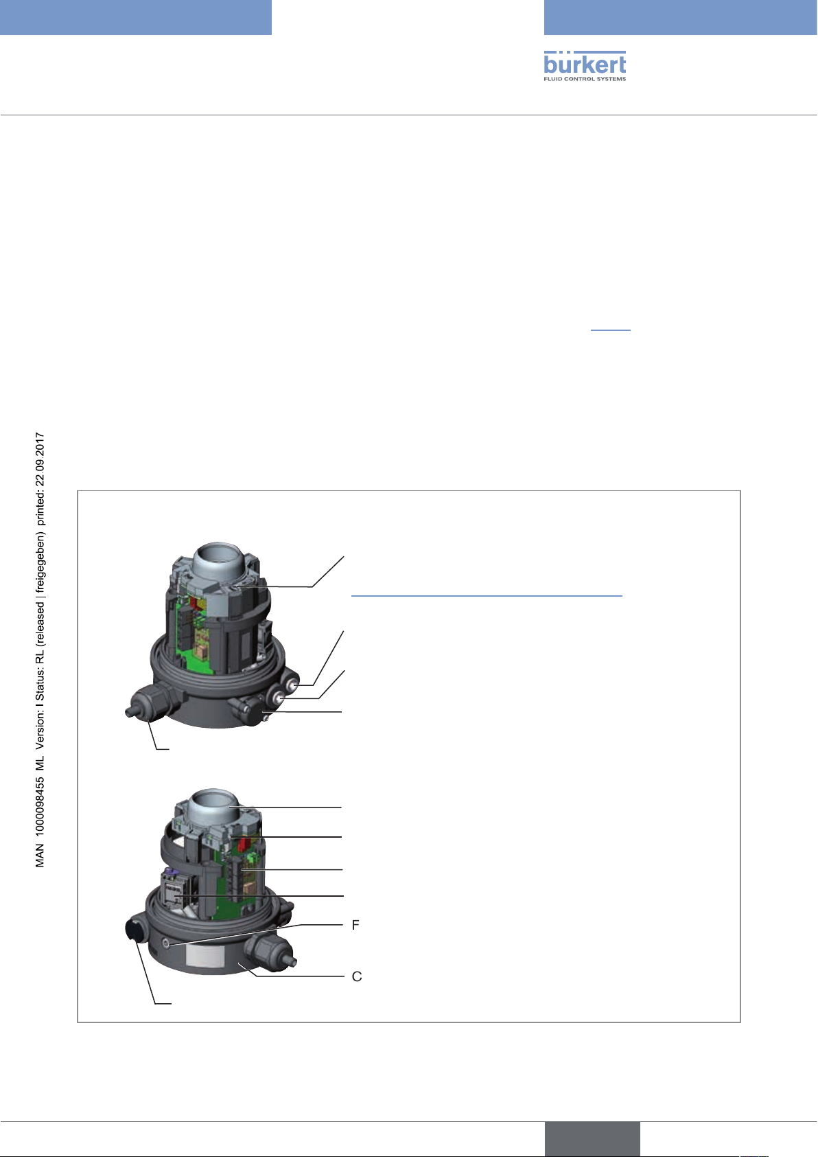
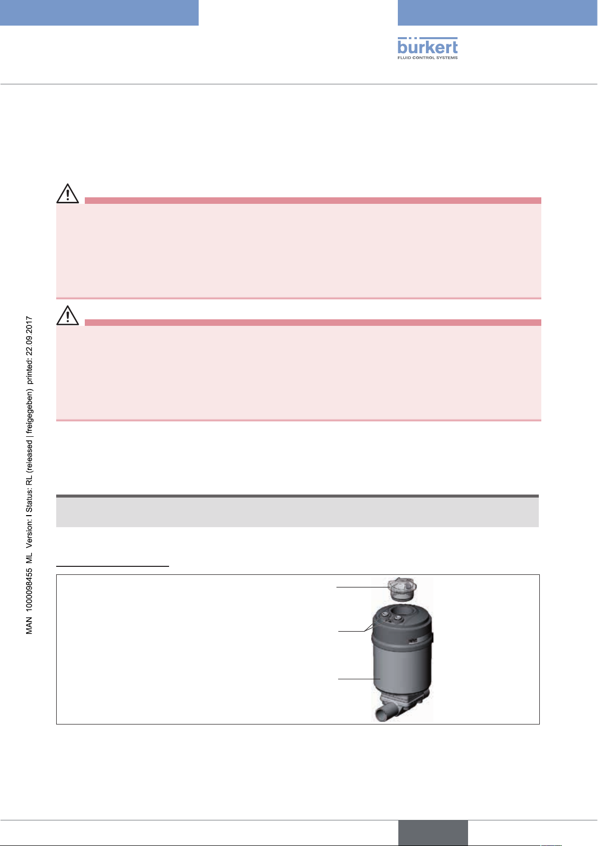
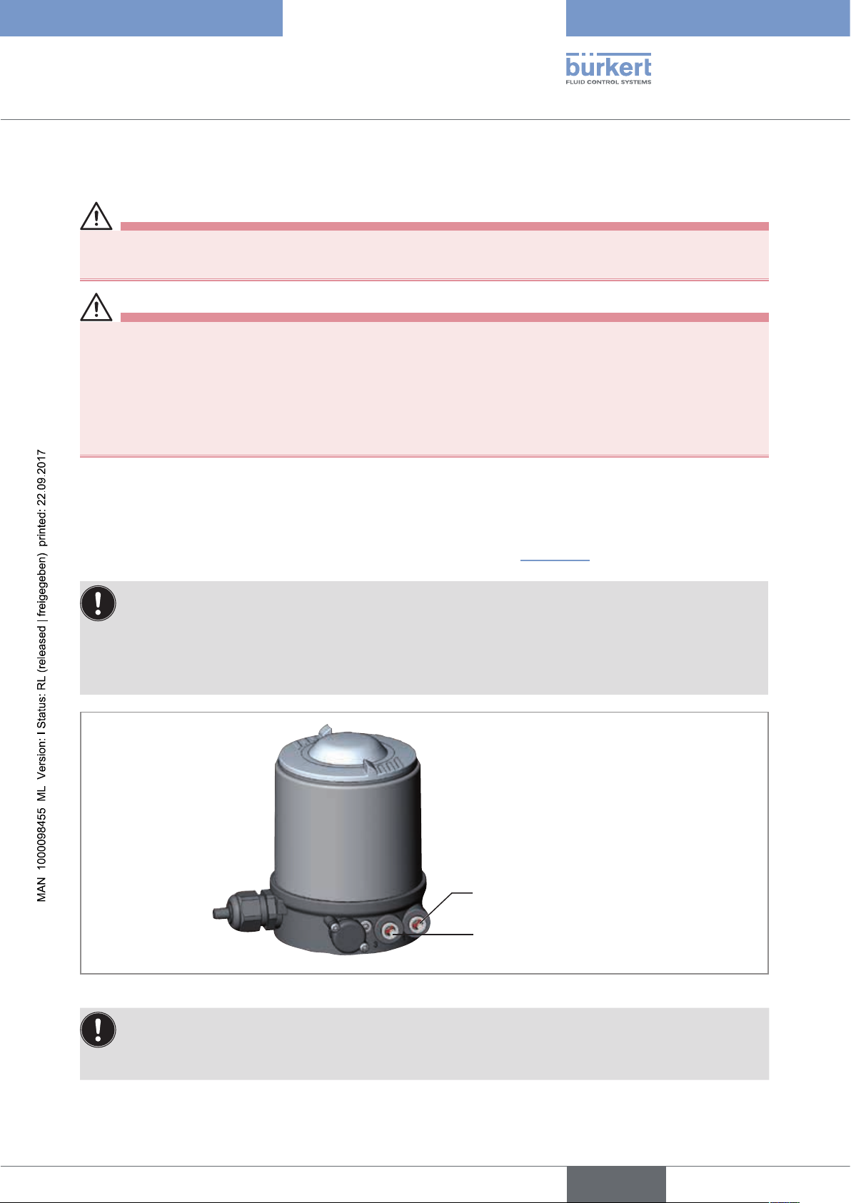
5.1.1 Control head for integrated installation on the 21xx series
Views without transparent cap and body casing
Teach function
Description see chapter on the appropriate model
„Teach function (calibrating the end positions)“
Pilot air port
label: 1
Exhaust air port
label: 3
Pressure limiting valve (for protection against too high internal
pressure in case of error)
24 V DC: Cable gland M16 x 1.5 or circular plug-in connector M12 x 1
Device status display (Top LEDs)
Status display pilot valve
Air intake filter (exchangeable)
Figure 1: Design and function
Screw terminals
Pilot valve (3/2-way or 5/2-way solenoid valve with hand lever)
Fastening screws (2x)
Connection housing
11
english
Page 12
Type 8691
System description
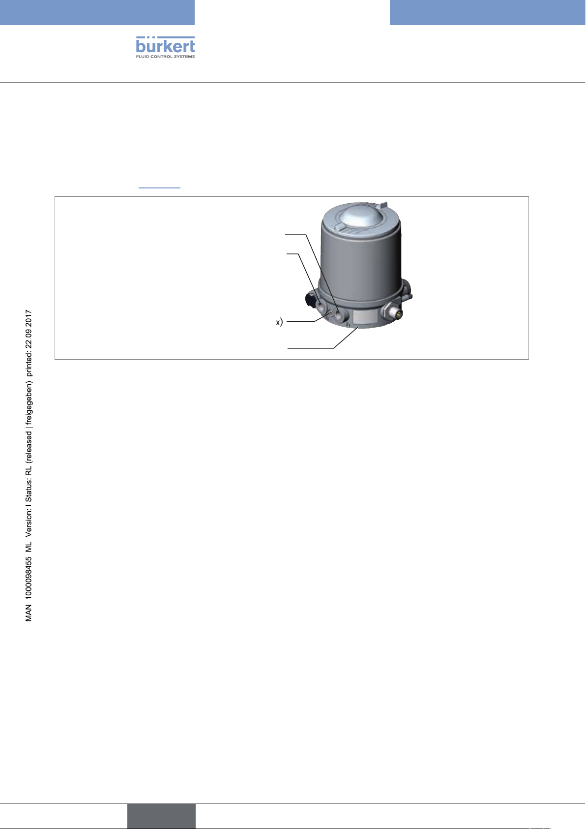
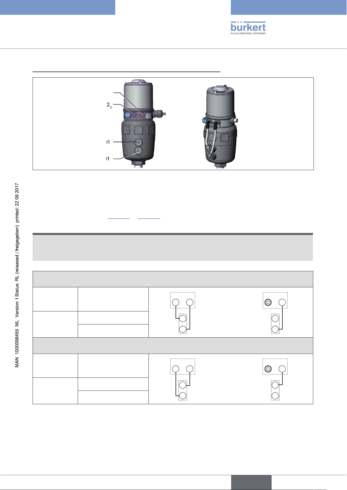
5.1.2 Model for control of process valves belonging to the 20xx
series
A special model enables the control head Type 8691 to be attached to process valves belonging to the 20xx series.
This model features has a different connection housing so that the pilot air ports can be connected to the outside
of the actuator (see “Figure 2”).
Pilot air outlet 2
Pilot air outlet 2
1
2
Fastening screws (2 x)
Connection housing
Figure 2: Connection module for process valves belonging to the 20xx series
12
english
Page 13
Type 8691
Technical data
6 TECHNICAL DATA
6.1 Conformity
In accordance with the EC Declaration of conformity, the control head Type 8691 is compliant with the EC
Directives.
6.2 Standards
The applied standards on the basis of which compliance with the EC Directives is confirmed are listed in the EC
type examination certificate and/or the EC Declaration of Conformity.
6.3 Licenses
The product is approved for use in zone 2 and 22 in accordance with ATEX directive 94/9/EC category 3GD.
Observe instructions on operation in an explosion-risk (Ex) area.
Observe the ATEX additional instructions.
The product is cULus approved. Instructions for use in the UL area see chapter “6.8 Electrical data”.
6.4 Operating conditions
WARNING!
Solar radiation and temperature fluctuations may cause malfunctions or leaks.
▶ If the device is used outdoors, do not expose it unprotected to the weather conditions.
▶ Ensure that the permitted ambient temperature does not exceed the maximum value or drop below the mini-
mum value.
Ambient temperature see type label
Degree of protection
Evaluated by the manufacturer: Evaluated by UL:
IP65 / IP67 according to EN 60529
1) Only if cables, plugs and sockets have been connected correctly and in compliance with the exhaust air concept see
chapter “8 Pneumatic installation”.
1)
UL Type 4x Rating
1)
6.5 Mechanical data
Dimensions see data sheet
Body material exterior: PPS, PC, VA
Sealing material exterior: EPDM
interior: NBR
Stroke range of valve spindle 2 – 28 mm
2 – 47 mm
13
english
Page 14
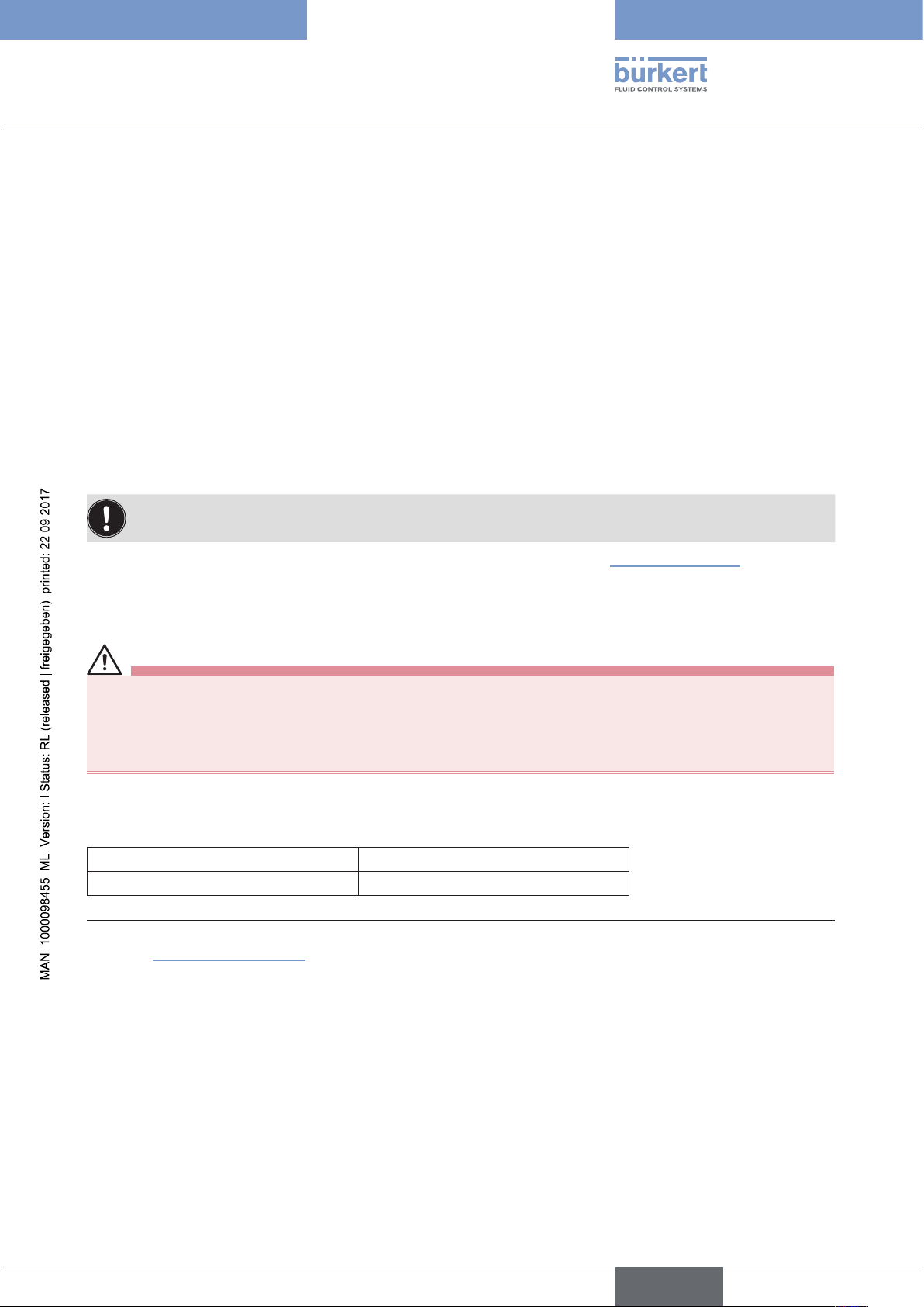
6.6 Type labels
6.6.1 Type label standard
Example:
Supply voltage / control
Type
8691 AS-i 62SI
single act Pilot 3,0
Pmax 7bar
Tamb 0°C - +55°C
Ser.-Nr. 001000
00179024
D-74653 Ingelfingen
W14UN
Type 8691
Technical data
Control function - pilot valve
Max. operating pressure
Max. ambient temperature
CE
Serial number - CE mark
Identification number
Figure 3: Example of type label
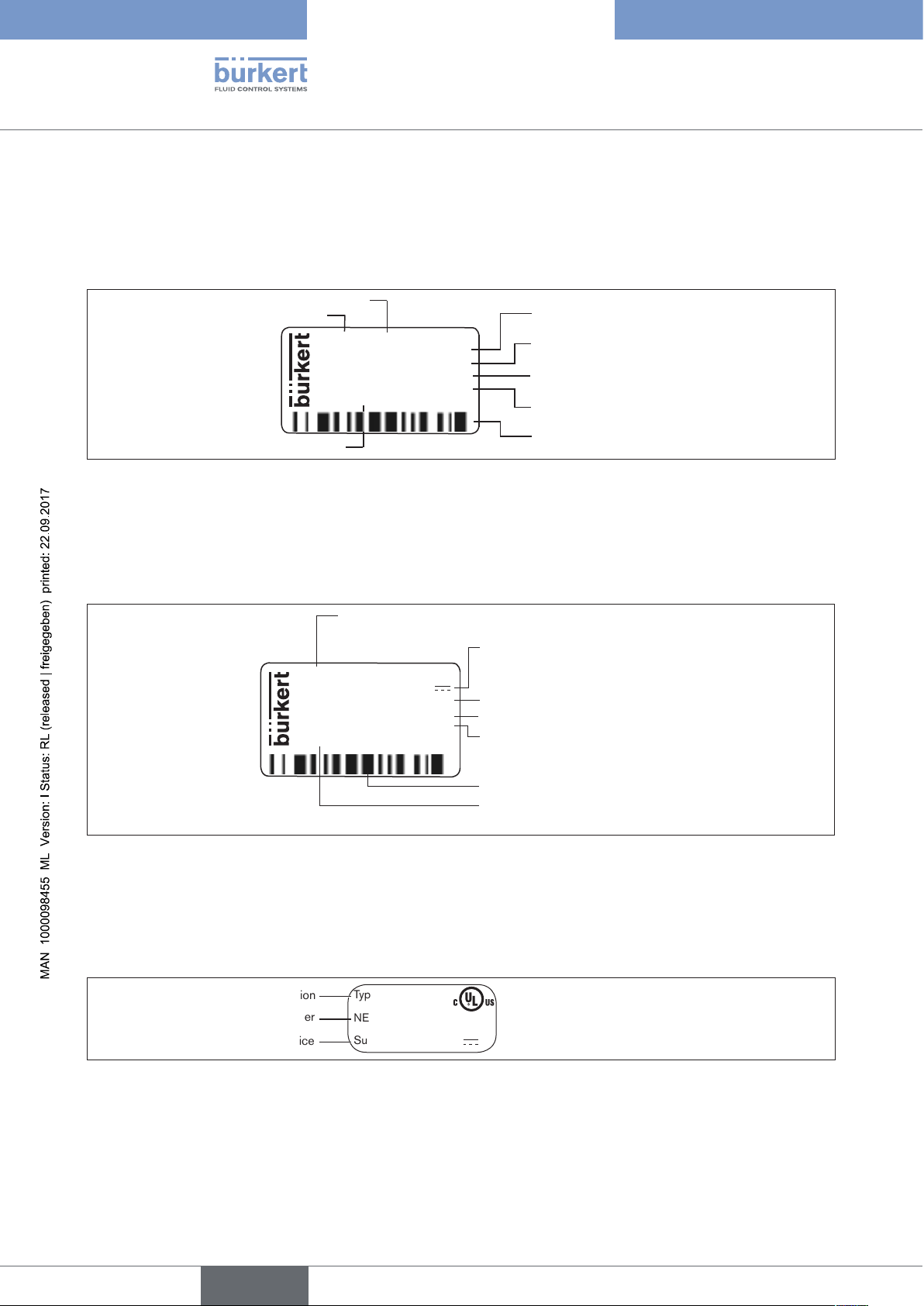
6.6.2 UL Type label
Example:
8691 -E3-...-0 PU02
Single act Pilot 3.0 24V
Pmax 7 bar
Tamb -10 - +55 °C
S/N 1001
00123456
D-74653 Ingelfingen
Figure 4: UL Type label (example)
Bar code
Type; Features of the type code applicable to UL
and ATEX
Control function; pilot valve;
Supply voltage pilot valve
Max. operating pressure
CE
W15MA
Max. ambient temperature
Serial number; CE mark
Bar code
Identification number; Date of
manufacture (encoded)
14
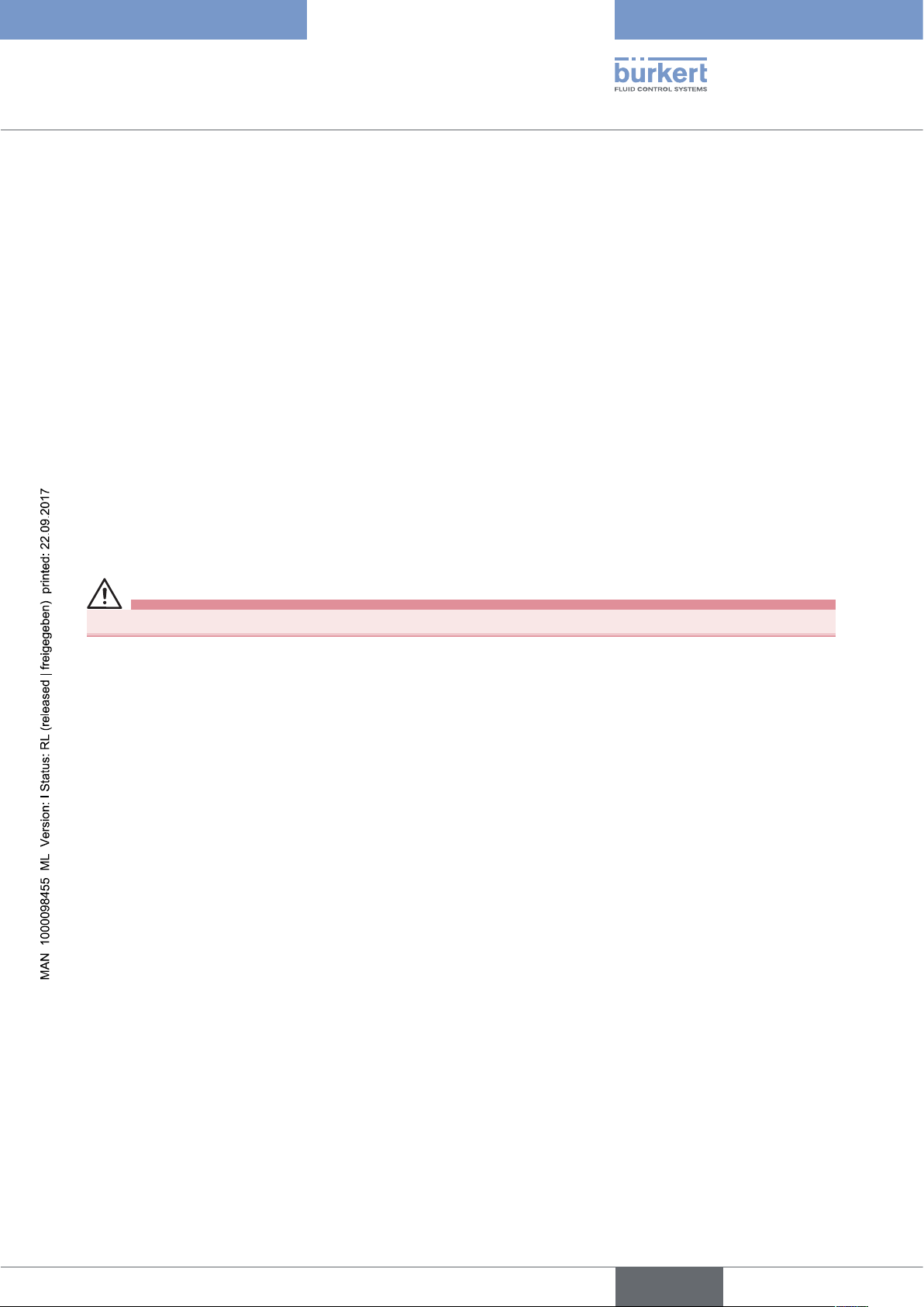
6.6.3 UL additional label
Example:
Degree of protection
Circuit with limited power
Supply voltage device
Figure 5: UL additional label (example)
english
Type 4X enclosure
NEC Class 2 only
Supply voltage: 24 V
Page 15
Type 8691
Technical data
6.7 Pneumatic data
Control medium neutral gases, air; Quality classes in accordance with ISO 8573-1
Dust content Class 7 max. particle size 40 µm, max. particle density 10 mg/m
3
Water content Class 3 max. pressure dew point
-20 °C or min. 10 °C below the lowest operating temperature
Oil content Class X max. 25 mg/m
3
Temperature range -10 – +50 °C
Pressure range 3 – 7 bar
Air output of pilot valve 250I
/min (for ventilation and exhaust)
N
(QNn value according to definition for pressure drop from 7 to 6 bar absolute)
Connections Plug-in hose connector Ø 6 mm / 1/4"
Socket connection G1/8
6.8 Electrical data
WARNING!
Only circuits with limited power may be used for UL approved components according to “NEC Class 2”.
6.8.1 Electrical data without bus control 24 V DC
Protection class 3 as per DIN EN 61140 (VDE 0140-1)
Connections Cable gland M16 x 1.5, wrench size 22 (clamping area 5 – 10 mm)
with screw-type terminals for cable cross-sections 0.14 – 1.5 mm²
Circular plug-in connector (M12 x 1, 8-pole)
Pilot valve
Operating voltage 24 V DC ± 10 % residual ripple 10 %
Power input max. 1W
Output max. 100 mA per output
Display max. 20 mA per illustrated illuminated display (LED)
6.8.2 Electrical data with AS-Interface bus control
Protection class 3 as per DIN EN 61140 (VDE 0140-1)
Connections Circular plug-in connector (M12 x 1, 4-pole)
Operating voltage 29.5 V – 31.6 V DC (according to specification)
Outputs
Max. switching capacity 1 W via AS-Interface
Watchdog function integrated
english
15
Page 16

Type 8691
Technical data
Devices without external supply voltage:
Max. power consumption 120 mA
Power consumption input during normal operation
(after current reduction;
valve + 1 end position reached) 90 mA
Devices with external supply voltage:
External supply voltage 24 V ± 10 %
The power supply unit must
include a secure disconnection in
accordance with IEC 364-4-41
(PELV or SELV)
Max. power consumption 55 mA (after current reduction ≤ 30 mA)
Max. power consumption from AS-Interface 55 mA
6.8.3 Electrical data with DeviceNet bus control
Protection class 3 as per DIN EN 61140 (VDE 0140-1)
Connections Circular plug-in connector (M12 x 1, 5-pole)
Operating voltage 11 V – 25 V
Max. power consumption < 80 mA
Output Pull-in current current ≤ 50 mA
Holding current ≤ 30 mA
16
english
Page 17
Type 8691
Installation
7 INSTALLATION
7.1 Safety instructions
DANGER!
Risk of injury from high pressure in the equipment/device.
▶ Before working on equipment or device, switch off the pressure and deaerate/drain lines.
Risk of electric shock.
▶ Before working on equipment or device, switch off the power supply and secure to prevent reactivation.
▶ Observe applicable accident prevention and safety regulations for electrical equipment.
WARNING!
Risk of injury from improper installation.
▶ Installation may be carried out by authorized technicians only and with the appropriate tools.
Risk of injury from unintentional activation of the system and an uncontrolled restart.
▶ Secure system from unintentional activation.
▶ Following assembly, ensure a controlled restart.
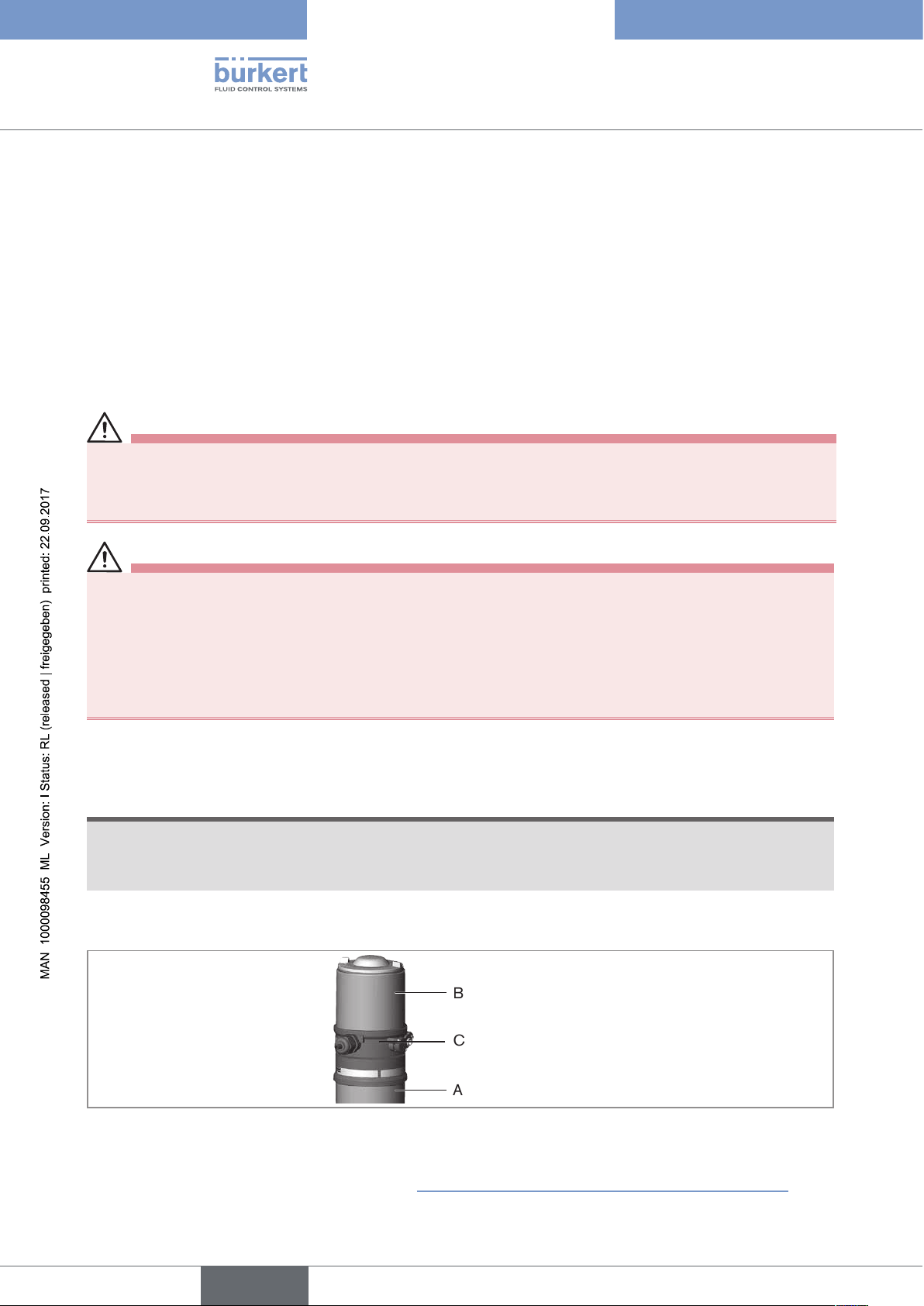
7.2 Installing the control head Type 8691 on process
valves belonging to series 21xx
NOTE!
When mounting on process valves with a welded body, follow the installation instructions in the operating instructions for the process valve.
Procedure:
1. Install switch spindle
Transparent cap
Pilot air ports
(plug-in hose connectors with collets or
threaded bushings)
Actuator
Figure 6: Installation of the switch spindle (1), 21xx series
→ Unscrew the transparent cap on the actuator and unscrew the position display (yellow cap) on the spindle
extension (if present).
english
17
Page 18
Type 8691
Installation
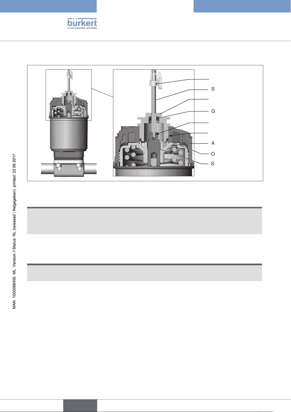
→ For model with plug-in hose connector, remove the collets (white nozzles) from both pilot air ports (if present).
Puck
Switch spindle
Guide element
Groove ring
max. 1 Nm
max. 5 Nm
Actuator cover
O-ring
Spindle extension
Figure 7: Installing of the switch spindle (2), series 21xx
NOTE!
Improper installation may damage the groove ring in the guide element.
The groove ring is already be pre-assembled in the guide element and must be “locked into position” in the undercut.
▶ When installing the switch spindle, do not damage the groove ring.
→ Push the switch spindle through the guide element.
NOTE!
Screw locking paint may contaminate the groove ring.
▶ Do not apply any screw locking paint to the switch spindle.
→ To secure the switch spindle, apply some screw locking paint (Loctite 290) in the tapped bore of the spindle
extension in the actuator.
18
→ Check that the O-ring is correctly positioned.
→ Screw the guide element to the actuator cover (maximum torque: 5 Nm).
→ Screw switch spindle onto the spindle extension. To do this, there is a slot on the upper side
(maximum torque: 1 Nm).
→ Push puck onto the switch spindle and lock into position.
english
Page 19
Type 8691
Installation
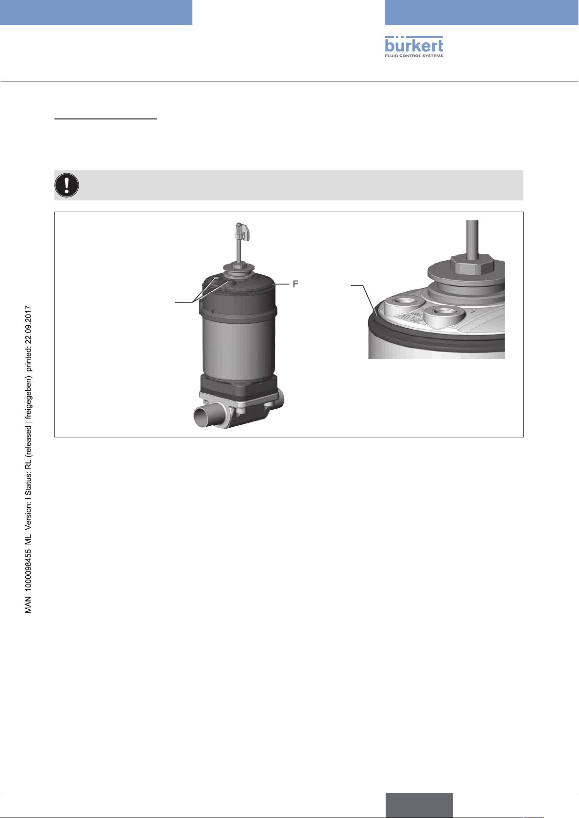
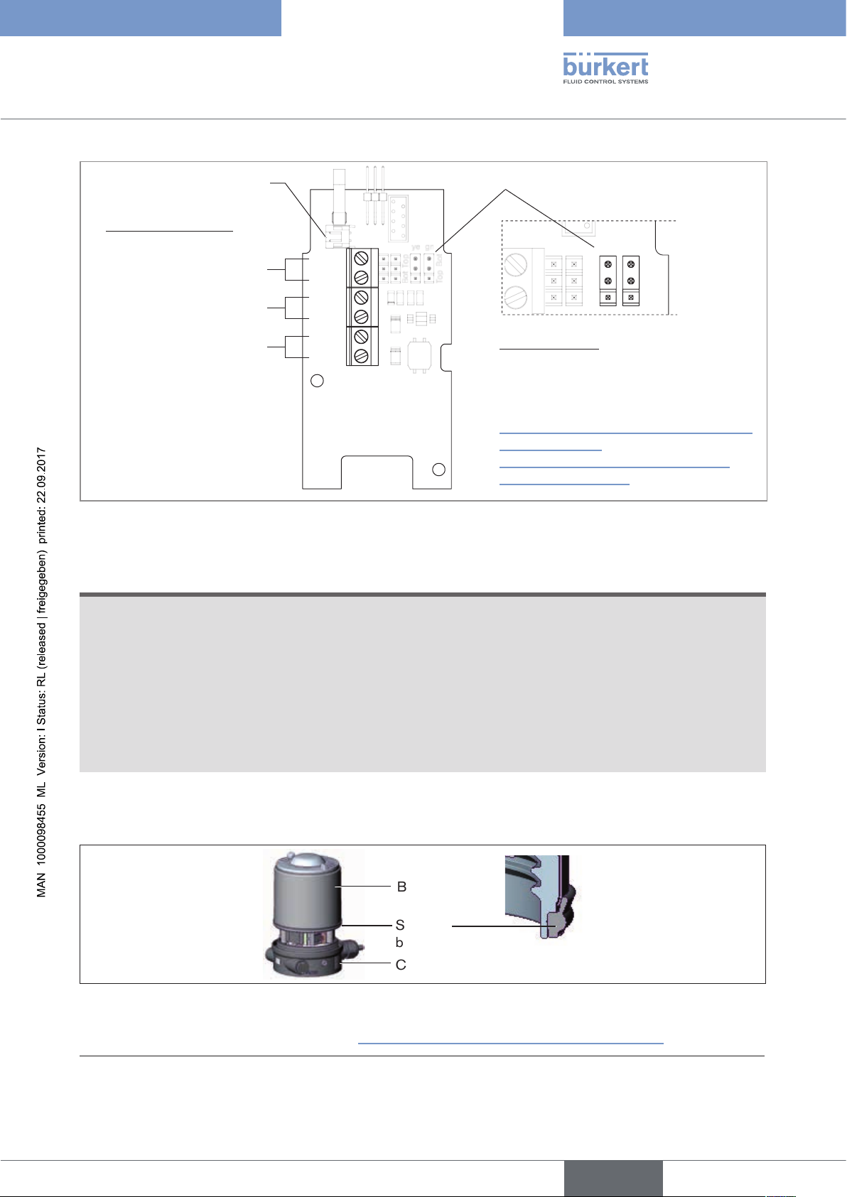
2. Install sealing rings
→ Pull the form seal onto the actuator cover (smaller diameter points upwards).
→ Check that the O-rings are correctly positioned in the pilot air ports.
When the control head is being installed, the collets of the pilot air ports must not be fitted to the actuator.
Form seal
Pilot air ports
Caution:
Collets must not be
fitted !
Figure 8: Installing of the sealing rings, 21xx series
Installation of the form
seal
english
19
Page 20

Type 8691
Installation
3. Install the control head
NOTE!
Damaged printed circuit board or malfunction.
▶ Ensure that the puck is situated flat on the guide rail.
→ Align the puck and the control head until
1. the puck can be inserted into the guide rail of the control head (see “Figure 9”) and
2. the connection pieces of the control head can be inserted into the pilot air ports of the actuator
(see “Figure 10”).
Guide rail
Puck
Figure 9: Aligning the puck
→ Push the control head, without turning it, onto the actuator until no gap is visible on the form seal.
NOTE!
Too high torque when screwing in the fastening screw does not ensure degree of protection IP65 /
IP67.
▶ The fastening screws may be tightened to a maximum torque of 1.5 Nm only.
→ Attach the control head to the actuator using the two side fastening screws. In doing so, tighten the screws
only hand-tight (max. torque: 1.5 Nm).
Connection pieces
Pilot air ports
Fastening screws
max. 1.5 Nm
20
Figure 10: Installation of control head, series 21xx
english
Page 21
Type 8691
Installation
7.3 Installing the control head Type 8691 on process
valves belonging to series 20xx
Procedure:
1. Install switch spindle
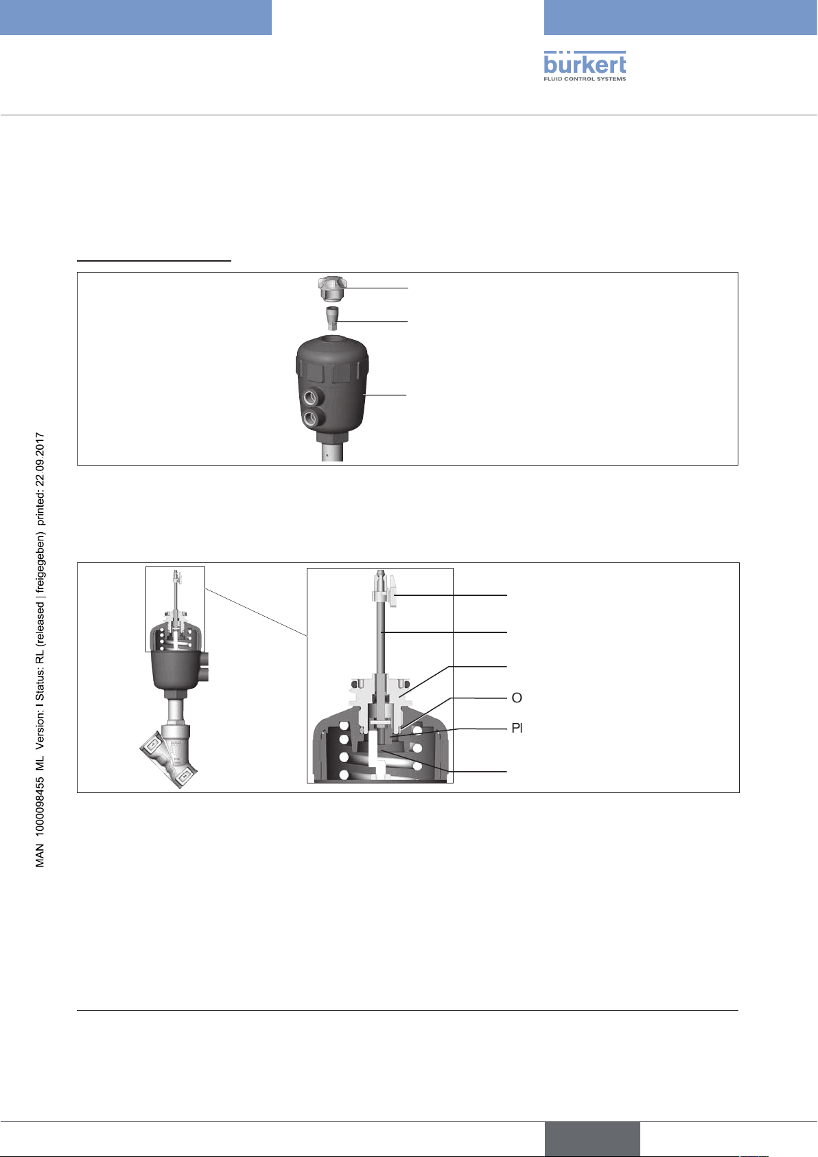
Transparent cap
Position indicator
Actuator
Figure 11: Installation of the switch spindle (1), series 20xx
→ Unscrew the transparent cap on the actuator.
→ Using a hexagon socket key, unscrew the orange/yellow position indicator from the inside of the actuator.
Puck
Switch spindle
Guide element
O-ring
Plastic part
(of the switch spindle)
Spindle (actuator)
Figure 12: Installation of the switch spindle (2), series 20xx
→ Press the O-ring downwards into the cover of the actuator.
→ Manually screw the switch spindle (and the plugged-on guide element) together with the plastic part onto the
spindle of the actuator, but do not tighten spindle yet.
→ Tighten the guide element with a face wrench
2)
into the actuator cover (torque: 8.0 Nm).
→ Tighten the switch spindle on the spindle of the actuator. To do this, there is a slot on the upper side (torque:
1.0 Nm).
→ Push the puck onto the switch spindle until it engages.
2) journal Ø: 3 mm; journal gap: 23.5 mm
english
21
Page 22
Type 8691
Installation
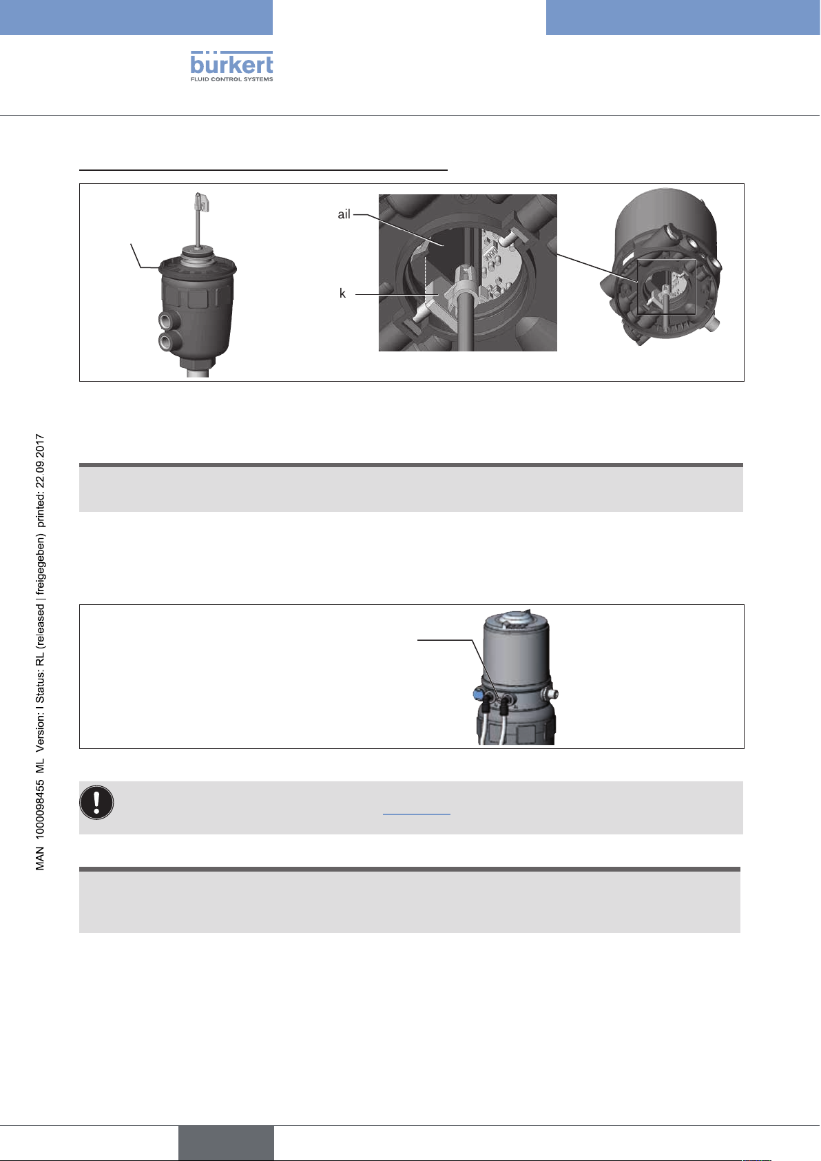
2. Installation of the masking ring and the control head
Guide rail
Masking ring
Puck
Figure 13: Installation of the masking ring and aligning the puck
→ Pull the masking ring onto the actuator cover (for actuator sizes ∅ 50 and ∅ 63 only).
NOTE!
Damaged printed circuit board or malfunction.
▶ Ensure that the puck is situated flat on the guide rail.
→ Push the control head onto the actuator. The puck must be aligned in such a way that it is inserted into the
guide rail of the control head.
→ Press the control head all the way down as far as the actuator and turn it into the required position.
Fastening screws
max. 1.5 Nm
Figure 14: Installation of the control head
Ensure that the pneumatic connections of the control head and those of the valve actuator are situated
preferably vertically one above the other (see “Figure 15”).
If they are positioned differently, longer hoses may be required other than those supplied in the accessory kit.
NOTE!
Too high torque when screwing in the fastening screw does not ensure degree of protection IP65 /
IP67.
22
▶ The fastening screws may be tightened to a maximum torque of 1.5 Nm only.
→ Attach the control head to the actuator using the two side fastening screws. In doing so, tighten the fastening
screws hand-tight only (maximum torque: 1.5 Nm).
english
Page 23
Type 8691
Installation
3. Install pneumatic connection between control head and actuator
Pilot air outlet 2
Pilot air outlet 2
Upper pilot air port
1
2
Example
∅ 80, CFA
Lower pilot air port
Figure 15: Installation of the pneumatic connection, 20xx series
→ Screw the plug-in hose connectors onto the control head and the actuator.
→ Using the hoses supplied in the accessory kit, make the pneumatic connection between the control head and
actuator with the following “Table 1” or “Table 2”.
NOTE!
Damage or malfunction due to ingress of dirt and moisture.
▶ To comply with degree of protection IP65 / IP67, connect the pilot air outlet which is not required (on CFA
and CFB) to the free pilot air port of the actuator or seal with a plug.
Control function A (CFA)
Process valve closed in rest position (by spring force)
Control head Pilot air outlet
Actuator
Upper pilot air port
Lower pilot air port
Control function B (CFB)
Process valve open in rest position (by spring force)
Control head Pilot air outlet
Actuator
Upper pilot air port
Lower pilot air port
Table 1: Pneumatic connection to actuator CFA and CFB
222
222
1
222
1
or
1
222
1
or
english
23
Page 24
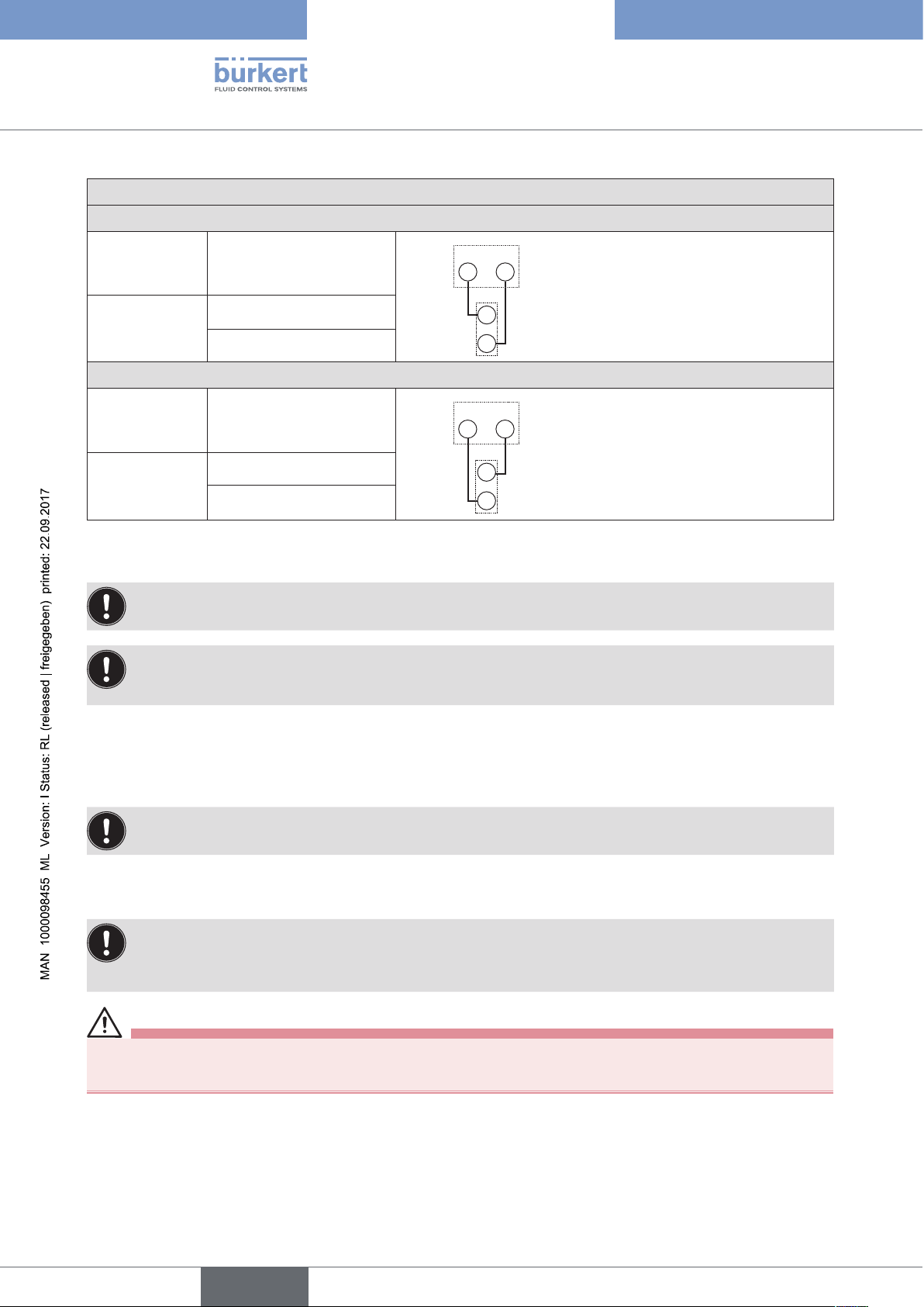
Control function I (CFI)
Process valve closed in rest position
Control head Pilot air outlet
222
Type 8691
Installation
1
Actuator
Upper pilot air port
Lower pilot air port
Process valve open in rest position
Control head Pilot air outlet
Actuator
Upper pilot air port
222
1
Lower pilot air port
Table 2: Pneumatic connection to actuator CFI
"In rest position" means that the pilot valves of the control head Type 8691 are isolated or not actuated.
If the ambient air is humid, a hose can be connected between pilot air outlet 22 of the control head and the
unconnected pilot air port of the actuator for control function A or control function B. As a result, the spring
chamber of the actuator is supplied with dry air from the vent duct of the control head.
24
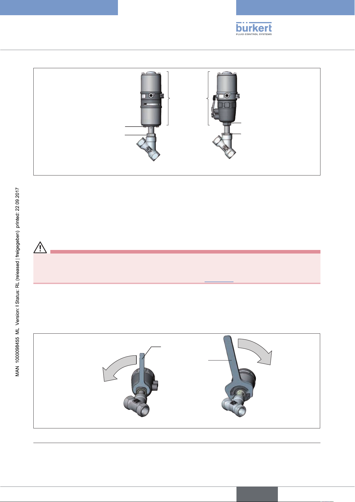
7.4 Rotating the actuator module
The actuator module (control head and actuator) can be rotated for straight seat valves and angle seat
valves only.
The position of the connections can be aligned steplessly by rotating the actuator module (control head and actuator)
through 360°.
Process valves Type 2100 and 2101: Only the entire actuator module can be rotated. The control head
cannot be rotated contrary to the actuator.
The process valve must be in the open position for alignment of the actuator module.
DANGER!
Risk of injury from high pressure in the equipment/device.
▶ Before working on equipment or device, switch off the pressure and deaerate/drain lines.
Procedure:
→ Clamp valve body in a holding device (only required if the process valve has not yet been installed).
→ Control function A: Open process valve.
english
Page 25
Type 8691
Installation
Actuator
module
Key contour
Nipple
Hexagon
Nipple
with hexagonwithout hexagon
Figure 16: Rotating the actuator module
→ Using a suitable open-end wrench, counter the wrench flat on the pipe.
→ Actuator module without hexagon:
Fit special key3) exactly in the key contour on the underside of the actuator.
→ Actuator module with hexagon:
Place suitable open-end wrench on the hexagon of the actuator.
WARNING!
Risk of injury from discharge of medium and pressure.
If the direction of rotation is wrong, the body interface may become detached.
▶ Rotate the actuator module in the specified direction only (see “Figure 17”).
→ Actuator module without hexagon:
Rotate clockwise (as seen from below) to bring the actuator module into the required position.
→ Actuator module with hexagon:
Rotate counter-clockwise (as seen from below) to bring the actuator module into the required position.
Open-end wrench
Special key
Figure 17: Rotating with special key / open-end wrench
3) The special key (665702) is available from your Bürkert sales office.
without hexagonwith hexagon
25
english
Page 26
Type 8691
Installation
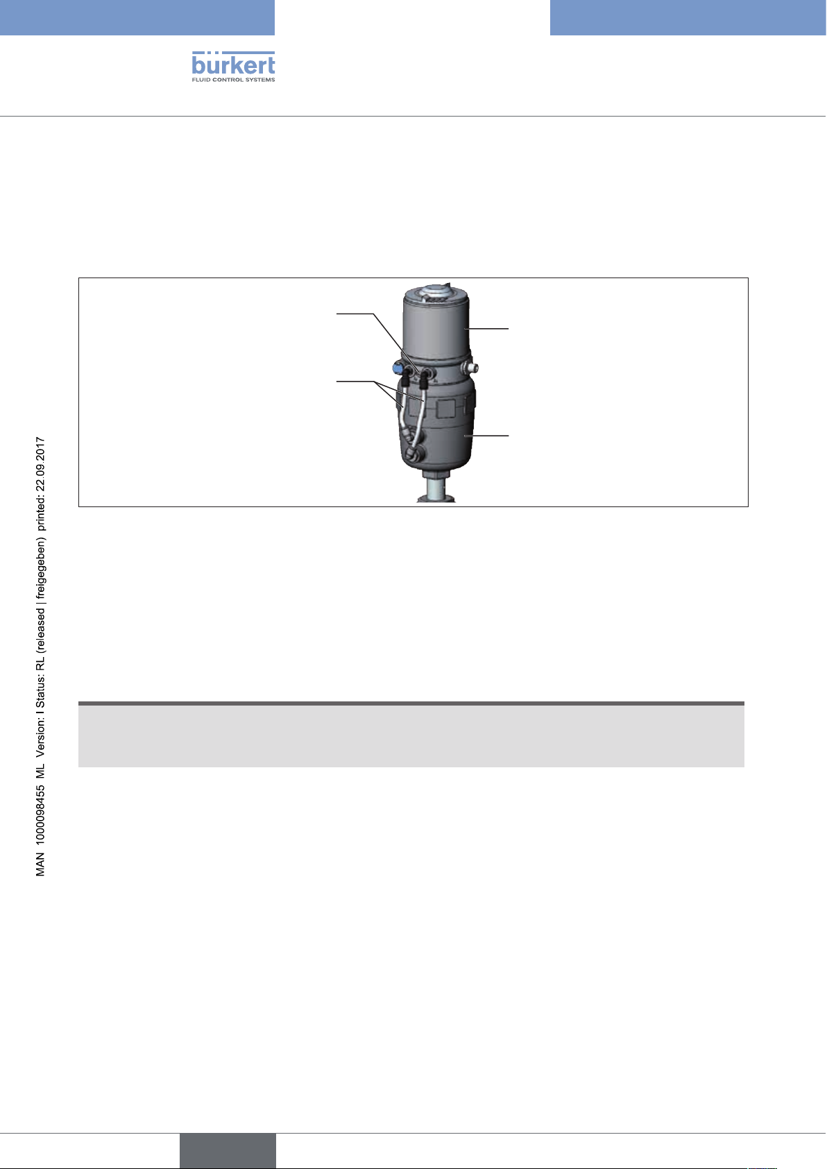
7.5 Rotating the control head for
process valves belonging to series 20xx
If the connecting cables or hoses cannot be fitted properly following installation of the process valve, the control
head can be rotated contrary to the actuator.
Fastening screw (2x)
Control head
Pneumatic connection
Actuator
Figure 18: Rotating the control head, series 20xx
Procedure
→ Loosen the pneumatic connection between the control head and the actuator.
→ Loosen the fastening screws (hexagon socket wrench size 2.5).
→ Rotate the control head into the required position.
NOTE!
Too high torque when screwing in the fastening screw does not ensure degree of protection IP65 /
IP67.
▶ The fastening screw may be tightened to a maximum torque of 1.5 Nm only.
→ Tighten the fastening screws hand-tight only (maximum torque: 1.5 Nm).
→ Re-attach the pneumatic connections between the control head and the actuator. If required, use longer
hoses.
26
english
Page 27
Type 8691
Pneumatic installation
8 PNEUMATIC INSTALLATION
DANGER!
Risk of injury from high pressure in the equipment/device.
▶ Before working on equipment or device, switch off the pressure and deaerate/drain lines.
WARNING!
Risk of injury from improper installation.
▶ Installation may be carried out by authorized technicians only and with the appropriate tools.
Risk of injury from unintentional activation of the system and an uncontrolled restart.
▶ Secure system from unintentional activation.
▶ Following installation, ensure a controlled restart.
Procedure:
→ Connect the control medium to the pilot air port (1)
(3 – 7 bar; instrument air, free of oil, water and dust).
→ Attach the exhaust airline or a silencer to the exhaust air port (3) (see “Figure 19”).
Important information for the problem-free functioning of the device:
▶ The installation must not cause back pressure to build up.
▶ Select a hose for the connection with an adequate cross-section.
▶ The exhaust air line must be designed in such a way that no water or other liquid can get into the device
through the exhaust air port.
Pilot air port
label: 1
Exhaust air port
label: 3
Figure 19: Pneumatic connection
Caution: (Exhaust air concept):
In compliance with degree of protection IP67, an exhaust air line must be installed in the dry area.
Keep the adjacent supply pressure always at least 0.5 – 1 bar above the pressure which is required to
move the actuator to its end position.
english
27
Page 28
Type 8691
Electrical installation 24 V DC
9 ELECTRICAL INSTALLATION 24 V DC
Two kinds of connections are used for the electrical bonding of the control head:
• Cable gland
with cable gland M16 x 1.5 and screw terminals
• Multi-pole
with circular plug-in connector M12 x 1, 8-pole
9.1 Safety instructions
DANGER!
Risk of electric shock.
▶ Before working on equipment or device, switch off the power supply and secure to prevent reactivation.
▶ Observe applicable accident prevention and safety regulations for electrical equipment.
WARNING!
Risk of injury from improper installation.
▶ Installation may be carried out by authorized technicians only and with the appropriate tools.
Risk of injury from unintentional activation of the system and an uncontrolled restart.
▶ Secure system from unintentional activation.
▶ Following installation, ensure a controlled restart.
9.2 Electrical installation with cable gland
NOTE!
Breakage of the pneumatic connection pieces due to rotational impact.
▶ When unscrewing and screwing in the body casing, do not hold the actuator of the process valve but the
connection housing.
→ Unscrew the body casing (stainless steel) in a counter-clockwise direction.
Body casing
28
Connection housing
Actuator
Figure 20: Open control head
→ Push the cables through the cable gland.
→ Connect the wires (see connection diagram in “Figure 21: Printed circuit board 24 V DC - cable gland”).
english
Page 29
Type 8691
Electrical installation 24 V DC
Valve connection
Jumper for assignment of Top LEDs
Connection diagram:
Screw terminals
End positions
Screw terminals
Supply 24 V DC
Screw terminals
Valve (control)
IN 1
IN 2
24 V
Valve
+
-
+
-
Jumper function:
You can set the color assignment of the
end positions with the jumpers.
see chapter
IN 1 = Top (top)
IN 2 = Bot (bottom)
“9.5.2 Device status display - assignment
of the Top LEDs” and
“9.5.3 Change assignment of the Top
LEDs (device status)”
Figure 21: Printed circuit board 24 V DC - cable gland
→ Check that the seal is correctly positioned in the body casing.
NOTE!
Breakage of the pneumatic connection pieces due to rotational impact.
ye
Top
Bot
gn
Bot
Top
▶ When unscrewing and screwing in the body casing, do not hold the actuator of the process valve but the
connection housing.
Damage or malfunction due to penetration of dirt and humidity.
To ensure degree of protection IP65 / IP67:
▶ Tighten the union nut on the cable gland according to the cable size or dummy plugs used. (ca. 1.5 Nm).
▶ Screw the body casing in all the way.
→ Tighten union nut on the cable gland (torque approx. 1.5 Nm).
→ Close the device (assembly tool: 674077
Figure 22: Position of the seal in the body casing
The teach function can now be used to automatically determine and read in the end positions of the valve
(description of the teach function see chapter “9.4 Teach function (calibrating the end positions)”).
4)
).
Body casing
Seal
body casing
Connection housing
4) The assembly tool (674077) is available from your Bürkert sales office.
29
english
Page 30
Type 8691
Electrical installation 24 V DC
9.3 Electrical installation with circular plug-in
connector
DANGER!
Risk of electric shock.
▶ Before working on equipment or device, switch off the power supply and secure to prevent reactivation.
▶ Observe applicable accident prevention and safety regulations for electrical equipment.
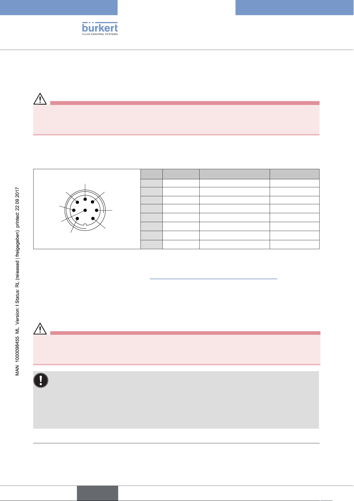
→ Connect the control head according to the table.
Configuration circular plug (M12 x 1, 8-pole):
Pin Wire color5)Designation Configuration
5
6
7
8
1
Table 3: Circular plug M12 x 1, 8-pole
4
3
2
1
2
3
4
5
6
7
8
white limit switch top IN 1 (= Top)
brown limit switch bottom IN 2 (= Bot)
green supply voltage GND
yellow supply voltage + 24 V DC
grey Valve control + Valve +
pink Valve control – Valve –
- not used
- not used
The teach function can now be used to automatically determine and read in the end positions of the valve
(description of the teach function see chapter “9.4 Teach function (calibrating the end positions)”).
9.4 Teach function (calibrating the end positions)
The teach function can be used to automatically determine and read in the end positions of the valve.
DANGER!
Risk of electric shock.
▶ Before working on equipment or device, switch off the power supply and secure to prevent reactivation.
▶ Observe applicable accident prevention and safety regulations for electrical equipment.
Necessary requirements:
Before you can actuate the teach function, you must
• mount the control head on the actuator,
• connect the supply voltage and
• connect the compressed-air supply.
30
5) The indicated colors refer to the connecting cable available as an accessory (919061)
english
Page 31

Type 8691
Electrical installation 24 V DC
Procedure:
Transparent cap
Body casing
Connection housing
Actuator
Figure 23: Open control head
NOTE!
Breakage of the pneumatic connection pieces due to rotational impact.
▶ When unscrewing and screwing in the transparent cap, do not hold the actuator of the process valve but the
connection housing.
→ Open the control head: turning the transparent cap anti-clockwise.
→ The key in recess for actuating the teach function keep pressed for approximately 5 seconds.
→ Only for control heads without pilot valve:
When yellow pilot valve LED is lit, move actuator to upper end position.
When yellow pilot valve LED goes out again, move actuator to lower end position.
NOTE!
Damage or malfunction due to penetration of dirt and humidity.
To ensure degree of protection IP65 / IP67:
▶ Screw the transparent cap in all the way.
→ Close the device (assembly tool: 674077
6)
).
Pilot valve LED (yellow)
Status LED: flashes yellow when teach function is running
Key in recess for actuating the teach function (keep
pressed for approximately 5 seconds)
Chronological description of the teach function:
• the bottom end position is read in internally
• the pilot valve switches
• the actuator moves automatically to the top end position
• the top end position is read in internally
• the pilot valve is turned off
• the actuator moves back to the bottom end position
Figure 24: Teach function
6) The assembly tool (674077) is available from your Bürkert sales office.
31
english
Page 32

Type 8691
Electrical installation 24 V DC
9.5 Display elements 24 V DC
9.5.1 LED status display
The LED status display (24 V DC) indicates whether the pilot valve is actuated (LED is lit yellow).
NOTE!
Breakage of the pneumatic connection pieces due to rotational impact.
▶ When unscrewing and screwing in the transparent cap, do not hold the actuator of the process valve but the
connection housing.
LED pilot valve (yellow)
Figure 25: LED status display, Status LED
Status LED yellow
LED yellow
flashing Teach function is running
Puck not available
flickers
→ Insert puck
Table 4: Status LED yellow - 24 V DC
Status LED (yellow)
Connection housing
32
NOTE!
Damage or malfunction due to penetration of dirt and humidity.
To ensure degree of protection IP65 / IP67:
▶ Screw the transparent cap in all the way.
english
Page 33

Type 8691
Electrical installation 24 V DC
9.5.2 Device status display - assignment of the Top LEDs
The device status of the control head (transparent cap) is displayed optically by colored high-power LEDs (Top LEDs).
NOTE!
Breakage of the pneumatic connection pieces due to rotational impact.
▶ When unscrewing and screwing in the transparent cap, do not hold the actuator of the process valve but the
connection housing.
Top LEDs
Figure 26: LED status display
The following functions are shown as standard:
Color
Device status
green Top LEDs on End position bottom
yellow Top LEDs off End position top
Table 5: Assignment of Top LEDs - 24 V DC
NOTE!
Damage or malfunction due to penetration of dirt and humidity.
To ensure degree of protection IP65 / IP67:
▶ Screw the transparent cap in all the way.
Connection housing
english
33
Page 34

2
Val
ye
gn
Top
Bot
Bot
Top
Type 8691
Electrical installation 24 V DC
9.5.3 Change assignment of the Top LEDs (device status)
DANGER!
Risk of electric shock.
▶ Before working on equipment or device, switch off the power supply and secure to prevent reactivation.
▶ Observe applicable accident prevention and safety regulations for electrical equipment.
Procedure:
NOTE!
Breakage of the pneumatic connection pieces due to rotational impact.
▶ When unscrewing and screwing in the body casing, do not hold the actuator of the process valve but the
connection housing.
→ Unscrew the body casing (stainless steel) in a counter-clockwise direction.
Body casing
Connection housing
Actuator
Figure 27: Open control head
→ Using the jumpers, assign the required color to the Top LEDs.
Jumper for assignment of Top LEDs
gn
ye
Bot
IN
ve
+
-
+
Top
Bot
Top
Jumper function:
You can set the color assignment of the end positions with
the jumpers.
You can indicate for each color whether it applies to the Top
(upper end position) or Bot (lower end position).
34
Figure 28: Assignment of the Top LEDs
english
Page 35

Type 8691
Electrical installation 24 V DC
→ Check that the seal is correctly positioned in the body casing.
NOTE!
Breakage of the pneumatic connection pieces due to rotational impact.
▶ When unscrewing and screwing in the body casing, do not hold the actuator of the process valve but the
connection housing.
Damage or malfunction due to penetration of dirt and humidity.
To ensure degree of protection IP65 / IP67:
▶ Screw the body casing in all the way.
→ Close the device (assembly tool: 674077
Figure 29: Position of the seal in the body casing
7)
).
Body casing
Seal
body casing
Connection housing
7) The assembly tool (674077) is available from your Bürkert sales office.
35
english
Page 36

Type 8691
AS-Interface installation
10 AS-INTERFACE INSTALLATION
10.1 AS-Interface connection
AS-Interface (Actuator Sensor Interface) is a field bus system which is used primarily for networking binary sensors
and actuators (slaves) with a higher-level control (master).
Bus line
Unshielded two-wire line (AS-Interface line as AS-Interface cable harness) along which both information (data) and
energy (supply voltage for the actuators and sensors) are transmitted.
Network topology
Freely selectable within wide limits, i.e. star, tree and line networks are possible. Further details describe the ASInterface specification (A/B slave model conforms to the version 3.0 specification).
10.2 Technical data for AS-Interface PCBs
Supply: via AS-Interface (29,5 V – 31,6 V)
Outputs: 1 valve Y1, max. 1 W, power reduction after approx. 100 ms
with integrated Watch Dog function
Certification: Licence no. 77601 according to version 3.0
10.3 Programming data
AS-Interface
31 slaves
I/O configuration B hex (1 input, 2 outputs)
ID code F hex A hex
Extended ID code 1 F hex 7 hex
Extended ID code 2 F hex E hex
Profile S-B.F.F S-B.A.E
Table 6: Programming data
Bit configuration
Data bit D3 D2 D1 D0
AS-Interface
62 slaves
36
Input
Output – – not used
Parameter bit P3 P2 P1 P0
Output not used not used not used
Table 7: Bit configuration
0 Top not reached
1 Top reached
english
0 Bot not reached
1 Bot reached
– –
0 Pilot valve OFF
1 Pilot valve ON
"0" START teach function
"1" STOP teach function
Page 37

Type 8691
AS-Interface installation
10.4 Electrical installation AS-Interface
10.4.1 Safety instructions
DANGER!
Risk of electric shock.
▶ Before working on equipment or device, switch off the power supply and secure to prevent reactivation.
▶ Observe applicable accident prevention and safety regulations for electrical equipment.
WARNING!
Risk of injury from improper installation.
▶ Installation may be carried out by authorized technicians only and with the appropriate tools.
Risk of injury from unintentional activation of the system and an uncontrolled restart.
▶ Secure system from unintentional activation.
▶ Following installation, ensure a controlled restart.
10.4.2 Connection with circular plug-in connector M12x1, 4-pole,
male
Bus connection without external / with external supply voltage
Pin Designation Configuration
1 Bus + AS-Interface bus line +
2 NC or GND (optional) not used or external supply voltage - (optional)
3 Bus – AS-Interface bus line 4 NC or 24 V + (optional) not used or external supply voltage + (optional)
Table 8: Pin assignment circular plug-in connector AS-Interface
Views of plug: From the front onto the pins, the soldered connections are behind
Pin 4:
NC
Pin 3:
Bus –
Pin 4:
24 V +
Pin 3:
Bus –
Pin 1:
Bus +
Figure 30: Bus connection without external supply
voltage
The teach function can now be used to automatically determine and read in the end positions of the valve
(description of the teach function see chapter “10.5 Teach function (calibrating the end position)”).
Pin 2:
NC
Pin 1:
Bus +
Figure 31: Bus connection with external supply voltage
(optional)
english
Pin 2:
GND
37
Page 38

Type 8691
AS-Interface installation
10.4.3 Connection with multi-pole cable and ribbon cable terminal
As an alternative to the bus connection model with 4-pole circular plug, there is the control head with multi-pole
cable (M12 circular plug) and ribbon cable terminal. The wiring diagram of the circular plug corresponds to the bus
connection of the M12 4-pole circular plug (see "Figure 25" and "Figure 26") and can easily be connected to the
ribbon cable terminal (see “Figure 32”).
Figure 32: Control head 8691 with multi-pole cable and ribbon cable terminal
Handling the ribbon cable terminal
The multi-pole cable features a ribbon cable terminal - with M12 plug-in connector branch circuit - for AS-Interface
cable harness. The ribbon cable terminal contacts the AS-Interface cable harness by means of penetration technology
which allows installation by “clipping in” the AS-Interface cable harness without cutting and without removing insulation.
Work steps:
→ Open the ribbon cable terminal
(loosen screws and remove cover)
→ Insert cable harness conclusively
→ Close ribbon cable terminal again
→ Tighten screws
Screws
M12 plug-in connector branch circuit
Figure 33: Ribbon cable terminal
Slightly undo thread-forming screws
(approx. 3/4 turn to the left) and position them on the
existing tapped bore and screw in.
38
The teach function can now be used to automatically determine and read in the end positions of the valve
(description of the teach function see chapter “10.5 Teach function (calibrating the end position)”).
english
Page 39

Type 8691
AS-Interface installation
10.5 Teach function (calibrating the end position)
The teach function can be used to automatically determine and read in the end positions of the valve.
For the bus variant AS-Interface, the teach function can also be started via the bus protocol.
DANGER!
Risk of electric shock.
▶ Before working on equipment or device, switch off the power supply and secure to prevent reactivation.
▶ Observe applicable accident prevention and safety regulations for electrical equipment.
Necessary requirements:
Before you can actuate the teach function, you must
• mount the control head on the actuator,
• connect the supply voltage,
• connect the compressed-air supply and
• pilot valve OFF (D0 = 0).
Procedure:
Transparent cap
Body casing
Connection housing
Actuator
Figure 34: Open control head
NOTE!
Breakage of the pneumatic connection pieces due to rotational impact.
▶ When unscrewing and screwing in the transparent cap, do not hold the actuator of the process valve but the
connection housing.
→ Open the control head: turning the transparent cap anti-clockwise.
→ The key in recess for actuating the teach function keep pressed for approximately 5 seconds.
→ Only for control heads without pilot valve:
When yellow pilot valve LED is lit, move actuator to upper end position.
When yellow pilot valve LED goes out again, move actuator to lower end position.
english
39
Page 40

NOTE!
Damage or malfunction due to penetration of dirt and humidity.
To ensure degree of protection IP65 / IP67:
▶ Screw the transparent cap in all the way.
Type 8691
AS-Interface installation
→ Close the device (assembly tool: 674077
8)
).
Pilot valve LED (yellow)
Status LED:
flashes yellow when teach function is running
Key in recess for actuating the teach function (keep
pressed for approximately 5 seconds
Chronological description of the teach function:
• the bottom end position is read in internally
• the pilot valve switches
• the actuator moves automatically to the top end position
• the top end position is read in internally
• the pilot valve is turned off
• the actuator moves back to the bottom end position
40
Figure 35: Teach function
When the teach function is activated the actuator cannot be actuated via the AS-Interface communication.
8) The assembly tool (674077) is available from your Bürkert sales office.
english
Page 41

Type 8691
AS-Interface installation
10.6 Display elements AS-Interface
10.6.1 LED status display
NOTE!
Breakage of the pneumatic connection pieces due to rotational impact.
▶ When unscrewing and screwing in the transparent cap, do not hold the actuator of the process valve but the
connection housing.
Status LED yellow
Top LEDs
Pilot valve LED yellow
Bus LED green
Bus LED red
Connection housing
Figure 36: LED status display - AS-Interface
Status LED yellow
LED yellow
flashing Teach function is running
flickers
Puck not available
→ Insert puck
Table 9: Status LED yellow - AS-Interface
Valve LED yellow
The yellow LED (valve) indicates whether the pilot valve is actuated (LED is lit yellow).
english
41
Page 42

Type 8691
AS-Interface installation
Bus LED red and green
The red and green LEDs (bus) indicate the bus status:
LED green LED red
off off POWER OFF
off on No data traffic (expired Watch Dog at slave address does not equal 0)
on off OK
flashing on Slave address equals 0
off flashing Sensor supply overloaded or external reset
flashing flashing Teach function error (periphery error)
Table 10: LED Status display bus status
NOTE!
Damage or malfunction due to penetration of dirt and humidity.
To ensure degree of protection IP65 / IP67:
▶ Screw the transparent cap in all the way.
10.6.2 Device status - assignment of the LEDs
The device status of the control head (transparent cap) is displayed optically by colored high-power LEDs (Top
LEDs).
The following functions are shown as standard
Color Device status
green Top LEDs on End position bottom
yellow Top LEDs on End position top
red LED flashing
alternately with the green or
yellow Top LEDs
Table 11: Assignment of Top LEDs - AS-Interface
no data traffic
or
Teach function error
42
english
Page 43

Type 8691
AS-Interface installation
10.6.3 Change assignment of the Top LEDs (device status)
DANGER!
Risk of electric shock.
▶ Before working on equipment or device, switch off the power supply and secure to prevent reactivation.
▶ Observe applicable accident prevention and safety regulations for electrical equipment.
Procedure:
NOTE!
Breakage of the pneumatic connection pieces due to rotational impact.
▶ When unscrewing and screwing in the body casing, do not hold the actuator of the process valve but the
connection housing.
→ Unscrew the body casing (stainless steel) in a counter-clockwise direction.
Body casing
Connection housing
Actuator
Figure 37: Open control head
→ Using the jumpers, assign the required color to the Top LEDs (see “Figure 38”).
Jumper for assignment of Top LEDs
Valve connection
Internal
connection
Jumper function:
You can set the color assignment of the end posi-
tions with the jumpers.
Figure 38: AS-Interface PCB
You can indicate for each color whether it applies
to the Top (upper end position) or Bot (lower end
position).
43
english
Page 44

Type 8691
AS-Interface installation
→ Check that the seal is correctly positioned in the body casing.
NOTE!
Breakage of the pneumatic connection pieces due to rotational impact.
▶ When unscrewing and screwing in the body casing, do not hold the actuator of the process valve but the
connection housing.
Damage or malfunction due to penetration of dirt and humidity.
To ensure degree of protection IP65 / IP67:
▶ Screw the body casing in all the way.
→ Close the device (assembly tool: 674077
Figure 39: Position of the seal in the body casing
9)
).
Body casing
Seal
body casing
Connection housing
44
9) The assembly tool (674077) is available from your Bürkert sales office.
english
Page 45

Type 8691
DeviceNet
11 DEVICENET
11.1 Definition
• The DeviceNet is a field bus system which is based on the CAN protocol (Controller Area Network). It enables
actuators and sensors (slaves) to be networked with higher-level controllers (master).
• The control head in the DeviceNet is a slave device according to the Predefined Master/Slave Connection Set
stipulated in the DeviceNet specification. Polled I/O, Bit Strobed I/O and Change of State (COS) are supported
as an I/O connection variant.
• With DeviceNet it is necessary to differentiate between cyclical or event-driven high-priority process messages
(I/O Messages) and acyclical low-priority management messages (Explicit Messages).
• The protocol process conforms to the DeviceNet specification Release 2.0.
11.2 Technical data
EDS file BUE8691.EDS
Icons BUE8691.ICO
Baudrate 125 kbit/s, 250 kbit/s, 500 kbit/s (via DIP switches);
Factory setting: 125 kbit/s
Address 0 – 63 (via DIP switches);
Factory setting: 63
Process data 1 static input assembly (input: from the control head 8691 to the DeviceNet Master/Scanner)
1 static output assembly
11.3 Maximum line lengths
The maximum total line length (sum of trunk lines and drop lines) of a network depends on the baudrate.
11.3.1 Total line length according to DeviceNet specification
Baudrate
125 kbaud
250 kbaud
500 kbaud
Table 12: Total line length
10) According to DeviceNet specification.
If a different cable type is used, lower maximum values apply.
Maximum total line length
Thick cable Thin cable
500 m
250 m
100 m
10)
100 m for all baudrates
45
english
Page 46

11.3.2 Drop line length
Type 8691
DeviceNet
Baudrate
125 kbaud
250 kbaud
500 kbaud
Table 13: Drop line length
Length of the drop lines
Maximum length Maximum total length in the network
156 m
6 m for all baudrates
78 m
39 m
11.4 Safety setting if the bus fails
If the bus fails, the pilot valve is switched to a programmable safety setting (default: pilot valve isolated). For configuration data see chapter entitled “11.9 Configuring the control head”.
11.5 Interfaces
Bus + supply Bus
Control head 8691
DeviceNet
11.6 Electrical connection DeviceNet
The bus line is a 4-core cable with additional shielding which must conform to the DeviceNet specification.
The cable transmits both information (data) and energy (power supply for low-power actuators and sensors).
11.6.1 Safety instructions
DANGER!
Risk of electric shock.
▶ Before working on equipment or device, switch off the power supply and secure to prevent reactivation.
▶ Observe applicable accident prevention and safety regulations for electrical equipment.
WARNING!
Risk of injury from improper installation.
▶ Installation may be carried out by authorized technicians only and with the appropriate tools.
Risk of injury from unintentional activation of the system and an uncontrolled restart.
▶ Secure system from unintentional activation.
▶ Following installation, ensure a controlled restart.
46
english
Page 47

Type 8691
DeviceNet
11.6.2 Configuration of the PCB DeviceNet
LED – pilot valve (yellow)
Device status LED (two-colored: red/green)
Bus LED (two-colored: red/green)
Valve connection
Internal connection
Figure 40: DeviceNet PCB
DIP switches for
bus address and baudrate
11.6.3 Bus connection (circular connector M12 x 1, 5-pole, male)
The control head features a 5-pole micro-style circular connector.
The following configuration conforms to the DeviceNet specification.
Pin
Signal
Table 14: Pin assignment circular plug-in connector DeviceNet
1 2 3 4 5
Shielding V + V – CAN_H CAN_L
Pin 4: CAN_H
white
Data lines
Figure 41: View of plug from the front onto the pins, the soldered connections are behind
Pin 5: CAN_L
blue
Pin 1: Drain
(Shield)
Pin 3: V–
black
Pin 2: V+
red
Supply voltage
11 ... 25 V DC
max. power 3 W,
if valve is switched
11.7 Terminating circuit for DeviceNet systems
When installing a DeviceNet system, ensure that the terminating circuit of the data lines is correct.
The circuit prevents the occurrence of interference caused by signals reflected onto the data lines.
The trunk line must be terminated at both ends with resistors of 120 Ω each and 1/4 W power loss
(see “Figure 42: Network topology, DeviceNet”).
47
english
Page 48

Type 8691
DeviceNet
11.8 Network topology of a DeviceNet system
Line with a trunk line and several drop lines.
Trunk lines and drop lines consist of identical material (see diagram).
Trunk line
V +
V –
CAN_H
CAN_L
DeviceNet cable
Terminating
resistor
120 Ω
¼ W
T01 Tn
Subscriber 1 (node1) Subscriber n (node n)
Figure 42: Network topology, DeviceNet
Drop lines
DeviceNet cable,
max. 6 m long
11.9 Configuring the control head
11.9.1 DIP switches
Terminating
resistor
120 Ω
¼ W
48
Figure 43: DIP switches DeviceNet
8 DIP switches are available for configuration:
• DIP switches 1 to 6 for the DeviceNet address
• DIP switches 7 to 8 for the baudrate
english
Page 49

Type 8691
DeviceNet
DANGER!
Risk of electric shock.
▶ Before working on equipment or device, switch off the power supply and secure to prevent reactivation.
▶ Observe applicable accident prevention and safety regulations for electrical equipment.
Procedure:
NOTE!
Breakage of the pneumatic connection pieces due to rotational impact.
▶ When unscrewing and screwing in the body casing, do not hold the actuator of the process valve but the
connection housing.
→ Unscrew the body casing (stainless steel) in a counter-clockwise direction.
Body casing
Connection housing
Actuator
Figure 44: Open control head
→ Set the DIP switches according to the following tables.
Setting the DeviceNet address
MAC ID - Medium Access Control Identifier:
[DIP 1=off=0 / DIP 1=on=1 / MAC ID=DIP 1*2
DIP 1
[20=1]
DIP 2
[21=2]
DIP 3
[22=4]
off off off off off off 0
on off off off off off 1
off on off off off off 2
... ... ... ... ... ... ...
off on on on on on 62
on on on on on on 63
0
+DIP 2*21+ ... +DIP 6*25]
DIP 4
[23=8]
DIP 5
[24=16]
DIP 6
[25=32]
MAC ID
Table 15: Setting the DeviceNet address
49
english
Page 50

Setting the baudrate
Adjusting the control head to the baudrate of the network.
DIP 7 DIP 8 Baudrate
off off 125 kbaud
on off 250 kbaud
off on 500 kbaud
on on not permitted
Table 16: Setting the baudrate
→ Check that the seal is correctly positioned in the body casing.
NOTE!
Breakage of the pneumatic connection pieces due to rotational impact.
Type 8691
DeviceNet
▶ When unscrewing and screwing in the body casing, do not hold the actuator of the process valve but the
connection housing.
Damage or malfunction due to penetration of dirt and humidity.
To ensure degree of protection IP65 / IP67:
▶ Screw the body casing in all the way.
→ Close the device (assembly tool: 674077
11)
).
Body casing
Seal
body casing
Connection housing
Figure 45: Position of the seal in the body casing
Please note:
If the settings are changed by actuating the DIP switches, this change will not take effect until the
device is restarted.
50
For a restart
• briefly disconnect the control head from the supply voltage and reconnect or
• switch the supply voltage off/on or
• transmit an appropriate reset message.
11) The assembly tool (674077) is available from your Bürkert sales office.
english
Page 51

Type 8691
DeviceNet
11.10 Configuration of the process data
To transmit process data via an I/O connection, 1 static input and 1 static output assembly can be selected. These
assemblies contain selected attributes combined into one object so that process data can be transmitted collectively
via an I/O connection.
Process data can be accessed
• cyclically in the connection variants "Polled I/O" and "Bitstrobed I/O", with "Change of state", if input values
change, or
• acyclically via Explicit Messages.
The access path for acyclical access is: class 4
instance 1
attribute 3
With the Get_Attribute_Single service the input data can be accessed acyclically for reading.
With the Set_Attribute_Single service the output data can be accessed acyclically for writing.
•
1 data byte for inputs:
(sensors or initiators)
Bit Sensor Value assignment Bit Pilot valve Value assignment
Bit 0 End position
Bit 1 End position
Bit 2... not used 0 always
Bit 7
Table 17: Data byte for inputs Table 18: Data byte for outputs
0 Bot not reached
1 Bot reached
0 Top not reached
1 Top reached
1 data byte for outputs:
(actuators or valves)
Bit 0
Bit 1... not used 0 always
Bit 7
Y1 0 pilot valve OFF
1 pilot valve ON
english
51
Page 52

Type 8691
DeviceNet
11.11 Configuration of the safety position of pilot valves
for bus error
If a bus fault occurs, the bus status LED may assume the "Green flashing", "Red flashing" or "Red" status.
(For a description see “Status of the bus LED”, page 56)
The valve safety position and safety module attributes can be used to configure the pilot valve in the event of a bus fault.
If a bus fault occurs, the configuration data of the pilot valves can be accessed acyclically via Explicit Messages.
• The Get_Attribute_Single service stands for a read access of the configuration data.
• The Set_Attribute_Single service stands for a write access of the configuration data.
1 data byte for safety mode:
(Attribute address: class 150, instance 1, attributes 7)
Bit Mode Value assignment Bit Pilot valve Value assignment
Character-
Bit 0
Bit
1–7
Table 19: Data byte for safety mode Table 20: Data byte for valve safety position
istics in event
of bus fault
not used 0 always Bit 7
0 Output safety position
1 Retain last valve
position
1 data byte for valve safety position:
(Attribute address: class 150, instance 1, attributes 6)
Bit 0
Bit 1... not used 0 always
Y1
(pilot valve 1)
0 pilot valve 1 OFF
1 pilot valve 1 ON
52
english
Page 53

Type 8691
DeviceNet
11.12 Teach function (calibrating the end position)
The teach function can be used to automatically determine and read in the end positions of the valve.
For the bus variant DeviceNet, the teach function can also be started via the bus protocol as well as the
communicator software (see “11.12.1 Starting the teach function”).
DANGER!
Risk of electric shock.
▶ Before working on equipment or device, switch off the power supply and secure to prevent reactivation.
▶ Observe applicable accident prevention and safety regulations for electrical equipment.
Necessary requirements:
Before you can actuate the teach function, you must
• mount the control head on the actuator,
• connect the supply voltage,
• connect the compressed-air supply and
• connect to the Master.
Procedure:
Transparent cap
Body casing
Connection housing
Actuator
Figure 46: Open control head
NOTE!
Breakage of the pneumatic connection pieces due to rotational impact.
▶ When unscrewing and screwing in the transparent cap, do not hold the actuator of the process valve but the
connection housing.
→ Open the control head: turning the transparent cap anti-clockwise.
→ The key in recess for actuating the teach function keep pressed for approximately 5 seconds.
→ Only for control heads without pilot valve:
When yellow pilot valve LED is lit, move actuator to upper end position.
When yellow pilot valve LED goes out again, move actuator to lower end position.
english
53
Page 54

Type 8691
DeviceNet
Pilot valve LED (yellow)
Status LED:
flashes yellow when teach function is running
Key in recess for actuating the teach function (keep
pressed for approximately 5 seconds
Chronological description of the teach function:
• the bottom end position is read in internally
• the pilot valve switches
• the actuator moves automatically to the top end position
• the top end position is read in internally
• the pilot valve is turned off
• the actuator moves back to the bottom end position
Figure 47: Teach function
NOTE!
Damage or malfunction due to penetration of dirt and humidity.
To ensure degree of protection IP65 / IP67:
▶ Screw the transparent cap in all the way.
→ Close the device (assembly tool: 674077
When the teach function is activated the actuator cannot be actuated via the DeviceNet communication.
12)
).
54
12) The assembly tool (674077) is available from your Bürkert sales office.
english
Page 55

Type 8691
DeviceNet
11.12.1 Starting the teach function
The teach function can be started and read out via the "teach function" attribute.
User 2 can receive information through the read out:
• firstly he is informed whether the teach function is completed.
• after the teach function is completed, the result of the function can be read out.
Access occurs acyclically via Explicit Messages with the Set_Attribute_Single (write access) service and the
Get_Attribute_Single service (read access).
1 data byte for teach function:
(Attribute address: class 150, instance 1, attributes 8)
Set_Attribute_Single:
Bit Mode Value assignment
Bit 0 Teach function 0 Start teach function
Bit 1 not used – (only read access permitted)
Bit 2 – 7 not used 0 always
Table 21: Set_Attribute_Single
Get_Attribute_Single:
Bit Mode Value assignment
Bit 0 Teach function
Bit 1
Bit 2 – 7 not used 0 always
Table 22: Get_Attribute_Single
Result of teach function
(available after end of teach function)
0 Teach function is running
1 Teach function is completed
0 Teach function successfully completed
1 Teach function defective
11.13 Display elements DeviceNet
11.13.1 LED status display
Pilot valve LED (yellow)
Device status LED (two-colored: red/green)
Bus LED (two-colored: red/green)
Top LEDs
Status LED
(yellow)
Figure 48: LED display, DeviceNet
55
english
Page 56

Type 8691
DeviceNet
11.13.2 Function test of the status LEDs
When voltage has been applied (connection of the network line), the following function test is run for the twocolored device status LED and bus status LED:
• LED is briefly lit green (approx. 1/4 sec)
• LED is briefly lit red (approx. 1/4 sec)
• LED off
Then another function test is run during which the LEDs light up briefly
When the test is complete, the status LEDs indicate the device statuses which are described in the following
table.
Status of the bus LED
LED Device status Explanation Troubleshooting
• Connect other devices, if the
Off
Green
Flashes
green
Flashes
red
No power supply /
not online
Online, connection
to master exists
Online, without
connection to
master
Connection
time-Out
Red Critical fault
Table 23: Status of the bus LED
• Device is not supplied with voltage
• Device has still not ended Duplicate
MAC ID Test (test lasts approx. 2 sec)
• Device cannot end Duplicate MAC ID
Test.
• Normal operating status with established connection to the master
• Normal operating status without
established connection to the master
• One or more I/O connections are in
Time-Out state
• Another device with the same MAC
ID address is in the circuit
• No bus connection due to communication problems
device is the only network
subscriber,
• replace device
• Check baud rate
• check bus connection
• New connection establishment by
master to ensure that the I/O data
is transmitted cyclically.
• Check baud rate
• If required, replace device
56
Status of the device status LED
LED Device status Explanation
Off No supply • Device is not supplied with voltage
Green Device is working • Normal operating status
Table 24: Status of the device status LED
english
Page 57

Type 8691
DeviceNet
Status of the pilot valve LED
LED Explanation
Off • Pilot valve is not actuated
Yellow • Pilot valve is actuated
Table 25: Status of the pilot valve LED
NOTE!
Damage or malfunction due to penetration of dirt and humidity.
To ensure degree of protection IP65 / IP67:
▶ Screw the transparent cap in all the way.
11.13.3 Device status - assignment of the LEDs
The device status of the control head (transparent cap) is displayed optically by colored high-power LEDs (Top
LEDs). The assignment of the green and yellow Top LEDs to the end position can be changed via Explicit Messages (attribute address: class 150, instance 1, attribute 9) or via the communication software.
The following functions are shown as standard
Color Device status
green Top LEDs on End position bottom
yellow Top LEDs off End position top
red LED flashing
• online, without connection to the Master
alternately with the green or
yellow Top LEDs
• Connection time-out
• Critical error
Table 26: Assignment of Top LEDs, DeviceNet
Top LEDs
Status LED
(yellow)
Figure 49: Top LEDs and status LED, DeviceNet
NOTE!
Damage or malfunction due to penetration of dirt and humidity.
To ensure degree of protection IP65 / IP67:
▶ Screw the transparent cap in all the way.
57
english
Page 58

11.13.4 Status LED yellow
LED yellow
flashing Teach function is running
Type 8691
DeviceNet
flickers
Table 27: Status LED yellow, DeviceNet
Puck not available
→ Insert puck
NOTE!
Damage or malfunction due to penetration of dirt and humidity.
To ensure degree of protection IP65 / IP67:
▶ Screw the transparent cap in all the way.
58
english
Page 59

Type 8691
Safety positions
12 SAFETY POSITIONS
Safety positions after failure of the electrical or pneumatic auxiliary power:
Operating mode Designation Safety positions after failure of the auxiliary power
Electrical Pneumatic
Single-acting
up
down
Control function A
down down
up
down
up
down
Table 28: Safety positions
Single-acting
up up
Control function B
Double-acting
down not defined
Control function I
english
59
Page 60

Type 8691
Maintenance
13 MAINTENANCE
13.1 Service at the air intake filter
DANGER!
Risk of injury from high pressure in the equipment/device.
▶ Before working on equipment or device, switch off the pressure and deaerate/drain lines.
To protect the internal pilot valves and the actuator, the pressure supply air is filtered.
The direction of flow of the air intake filter in installed state is from the inside to the outside through the filter
material.
Quick connector
O-ring
Air intake filter
Figure 50: Service on the air intake filter
Procedure:
→ Unlock the quick connector by pressing the holding element and pulling out the air intake filter (if necessary,
use a suitable tool in between the recesses in the head of the filter).
→ Clean the filter or, if necessary, replace the filter.
→ Check inner O-ring and, if required, clean.
→ Insert the air intake filter all the way into the quick connector.
DANGER!
Risk of injury due to improper installation.
60
▶ Ensure that the air intake filter is installed correctly.
→ Check that the air intake filter is secure.
english
Page 61

Type 8691
Disassembly
14 DISASSEMBLY
14.1 Safety instructions
DANGER!
Risk of injury from high pressure in the equipment/device.
▶ Before working on equipment or device, switch off the pressure and deaerate/drain lines.
Risk of electric shock.
▶ Before working on equipment or device, switch off the power supply and secure to prevent reactivation.
▶ Observe applicable accident prevention and safety regulations for electrical equipment.
WARNING!
Risk of injury from improper disassembly.
▶ Disassembly may be carried out by authorized technicians only and with the appropriate tools.
Risk of injury from unintentional activation of the system and an uncontrolled restart.
▶ Secure system from unintentional activation.
▶ Following disassembly, ensure a controlled restart.
14.2 Disassembly the control head
Procedure:
1. Pneumatic connection
DANGER!
Risk of injury from high pressure in the equipment/device.
▶ Before working on equipment or device, switch off the pressure and deaerate/drain lines.
→ Loosen the pneumatic connection.
→ Series 20xx:
Loosen the pneumatic connection between control head and actuator.
61
english
Page 62

Type 8691
Disassembly
2. Electrical connection
DANGER!
Risk of electric shock.
▶ Before working on equipment or device, switch off the power supply and secure to prevent reactivation.
▶ Observe applicable accident prevention and safety regulations for electrical equipment.
Circular plug-in connector:
→ Loosen the circular connector.
Cable gland:
→ Open the control head: unscrewing the transparent cap in an anticlockwise direction.
→ Unscrew the screw terminals and pull out cables.
→ Close the control head.
3. Mechanical connection
→ Loosen the fastening screws.
→ Remove the control head upwards.
Pneumatic
connections
Actuator
Control head
Electrical
connection
circular plug-in
connector
Fastening
screws (2x)
Pneumatic con-
nection to the
actuator
62
Series 21xx
Figure 51: Disassembly the control head
english
Actuator
Series 20xx
Page 63

Type 8691
Accessories
15 ACCESSORIES
Designation Order no.
Connection cable M12 x 1, 8-pole 919061
Special key 665702
Assembly tool 674077
USB adapter for connection to a PC in conjunction with an extension cable 227093
Communicator
Table 29: Accessories
Information at
www.burkert.com
15.1 Communications software
The PC operating program “Communicator” is designed for communication with the devices Type 8691 with bus
control via DeviceNet. Devices constructed since April 2014 support the full range of functions. If you have any
questions regarding compatibility, please contact the Bürkert Sales Center.
A detailed description and precise schedule of the procedure for the installation and operation of the
software can be found in the associated documentation.
15.2 USB interface
The PC requires an USB interface for communication with the devices as well as an additional adapter with
interface driver (see “Table 29: Accessories”).
The data transfer must be according to HART specification.
15.3 Download
Download the software at: www.burkert.com
63
english
Page 64

Type 8691
Packaging and transport
16 PACKAGING AND TRANSPORT
Transport damages.
Inadequately protected equipment may be damaged during transport.
▶ Protect the unit against wet and dirt during transport and pack safely in shock-resistant packaging.
▶ Avoid the effects of heat and cold which could result in temperatures above or below the permitted storage
temperature.
17 STORAGE
Incorrect storage may damage the device.
▶ Store the device in a dry and dust-free location.
▶ Storage temperature: -20 – +65°C.
18 DISPOSAL
→ Dispose of the device and packaging in an environmentally friendly manner.
Damage to the environment caused by device components contaminated with media.
▶ Observe the relevant disposal and environmental protection regulations.
Note:
Observe the national waste disposal regulations.
64
english
Page 65

Typ 8691
Steuerkopf Typ 8691
InhalT
1 DIE BEDIENUNGSANLEITUNG .................................................................................................................................................69
1.1 Darstellungsmittel ..............................................................................................................................................................69
1.2 Begriffsdefinition / Abkürzung ....................................................................................................................................69
2 BESTIMMUNGSGEMÄSSE VERWENDUNG .......................................................................................................................70
2.1 Beschränkungen .................................................................................................................................................................70
3 GRUNDLEGENDE SICHERHEITSHINWEISE .....................................................................................................................71
4 ALLGEMEINE HINWEISE ..............................................................................................................................................................72
4.1 Kontaktadresse ....................................................................................................................................................................72
4.2 Gewährleistung ....................................................................................................................................................................72
4.3 Warenzeichen ........................................................................................................................................................................72
4.4 Informationen im Internet ...............................................................................................................................................72
5 SYSTEMBESCHREIBUNG ............................................................................................................................................................73
5.1 Aufbau und Funktion .........................................................................................................................................................73
5.1.1 Steuerkopf für den integrierten Anbau an 21xx ...........................................................................73
5.1.2 Variante zur Ansteuerung von Prozessventilen der Reihe 20xx ...............................................74
6 TECHNISCHE DATEN .....................................................................................................................................................................75
6.1 Konformität.............................................................................................................................................................................75
6.2 Normen .....................................................................................................................................................................................75
6.3 Zulassungen ..........................................................................................................................................................................75
6.4 Betriebsbedingungen .......................................................................................................................................................75
6.5 Mechanische Daten ...........................................................................................................................................................75
6.6 Typschilder .............................................................................................................................................................................76
6.6.1 Typschild Standard ............................................................................................................................76
6.6.2 UL-Typschild.........................................................................................................................................76
6.6.3 UL-Zusatzschild ................................................................................................................................... 76
6.7 Pneumatische Daten .........................................................................................................................................................77
deutsch
65
Page 66

Typ 8691
Inhaltsverzeichnis
6.8 Elektrische Daten ................................................................................................................................................................77
6.8.1 Elektrische Daten ohne Busansteuerung 24 V DC ....................................................................77
6.8.2 Elektrische Daten mit Busansteuerung AS-Interface ................................................................77
6.8.3 Elektrische Daten mit Busansteuerung DeviceNet.....................................................................78
7 MONTAGE .............................................................................................................................................................................................79
7.1 Sicherheitshinweise ..........................................................................................................................................................79
7.2 Montage des Steuerkopfs Typ 8691 an Prozessventile der Reihe 21xx...............................................79
7.3 Montage des Steuerkopfs Typ 8691 an Prozessventile der Reihe 20xx...............................................83
7.4 Drehen des Antriebsmoduls .........................................................................................................................................86
7.5 Drehen des Steuerkopfs bei Prozessventilen der Reihe 20xx ..................................................................88
8 PNEUMATISCHE INSTALLATION .............................................................................................................................................89
9 ELEKTRISCHE INSTALLATION 24 V DC ...............................................................................................................................90
9.1 Sicherheitshinweise ..........................................................................................................................................................90
9.2 Elektrische Installation mit Kabelverschraubung ..............................................................................................90
9.3 Elektrische Installation mit Rundsteckverbinder ...............................................................................................92
9.4 Teachfunktion (Einmessen der Endstellungen) .................................................................................................92
9.5 Anzeigeelemente 24 V DC .............................................................................................................................................94
9.5.1 LED - Zustandsanzeige.....................................................................................................................94
9.5.2 Gerätestatusanzeige - Zuordnung der Top LEDs .......................................................................95
9.5.3 Zuordnung der Top LEDs ändern (Gerätestatus) .......................................................................96
10 AS-INTERFACE-INSTALLATION ................................................................................................................................................98
10.1 AS-Interface-Anschaltung ..............................................................................................................................................98
10.2 Technische Daten für AS-Interface-Platinen ........................................................................................................98
10.3 Programmierdaten .............................................................................................................................................................98
66
10.4 Elektrische Installation AS-Interface ........................................................................................................................99
10.4.1 Sicherheitshinweise ...........................................................................................................................99
10.4.2 Anschluss mit Rundsteckverbinder M12 x 1, 4-polig, male .....................................................99
10.4.3 Anschluss mit Multipolkabel und Flachkabelklemme .............................................................. 100
10.5 Teachfunktion (Einmessen der Endstellungen) .............................................................................................. 101
deutsch
Page 67

Typ 8691
10.6 Anzeigeelemente AS-Interface ................................................................................................................................103
10.6.1 LED Zustandsanzeige ....................................................................................................................103
10.6.2 Gerätestatus - Zuordnung der Top LEDs .................................................................................. 104
10.6.3 Zuordnung der Top LEDs ändern (Gerätestatus) .................................................................... 105
11 DEVICENET-INSTALLATION ..................................................................................................................................................... 107
11.1 Begriffserklärung .............................................................................................................................................................107
11.2 Technische Daten ............................................................................................................................................................107
11.3 Maximale Leitungslängen ............................................................................................................................................ 107
11.3.1 Gesamtleitungslänge nach DeviceNet-Spezifikation .............................................................. 107
11.3.2 Stichleitungslänge (Drop Lines)................................................................................................... 108
11.4 Sicherheitsstellung bei Ausfall des Busses......................................................................................................108
11.5 Schnittstellen .....................................................................................................................................................................108
11.6 Elektrische Installation DeviceNet ..........................................................................................................................108
11.6.1 Sicherheitshinweise ........................................................................................................................ 108
11.6.2 Aufbau der Platine DeviceNet ...................................................................................................... 109
11.6.3 Bus-Anschluss (Rundstecker M12 x 1, 5-polig, male) ........................................................... 109
11.7 Abschlussbeschaltung für DeviceNet-Systeme..............................................................................................109
11.8 Netztopologie eines DeviceNet-Systems ...........................................................................................................110
11.9 Konfigurieren des Steuerkopfs ................................................................................................................................110
11.9.1 DIP-Schalter ..................................................................................................................................... 110
11.10 Konfiguration der Prozessdaten .............................................................................................................................. 113
11.11 Konfiguration der Sicherheitsstellung von Steuerventilen bei Busfehler .........................................114
11.12 Teachfunktion (Einmessen der Endstellungen) ..............................................................................................115
11.12.1 Starten der Teachfunktion ............................................................................................................. 117
11.13 Anzeigeelemente DeviceNet .....................................................................................................................................117
11.13.1 LED Zustandsanzeige .................................................................................................................... 117
11.13.2 Funktionstest der Geräte Status LED und Bus LED............................................................... 118
11.13.3 Gerätestatus - Zuordnung der Top LEDs .................................................................................. 119
11.13.4 Status LED gelb............................................................................................................................... 120
12 SICHERHEITSSTELLUNGEN ................................................................................................................................................... 121
deutsch
67
Page 68

Typ 8691
13 WARTUNG .........................................................................................................................................................................................122
13.1 Service am Zuluftfilter ...................................................................................................................................................122
14 DEMONTAGE ................................................................................................................................................................................... 123
14.1 Sicherheitshinweise ....................................................................................................................................................... 123
14.2 Demontage Steuerkopf ................................................................................................................................................ 123
15 ZUBEHÖR ..........................................................................................................................................................................................125
15.1 Kommunikationssoftware ...........................................................................................................................................125
15.2 USB-Schnittstelle ............................................................................................................................................................125
15.3 Download .............................................................................................................................................................................125
16 VERPACKUNG, TRANSPORT ..................................................................................................................................................126
17 LAGERUNG ....................................................................................................................................................................................... 126
18 ENTSORGUNG ................................................................................................................................................................................ 126
68
deutsch
Page 69

Typ 8691
Die Bedienungsanleitung
1 DIE BEDIENUNGSANLEITUNG
Die Bedienungsanleitung beschreibt den gesamten Lebenszyklus des Geräts. Bewahren Sie diese Anleitung so auf,
dass sie für jeden Benutzer gut zugänglich ist und jedem neuen Eigentümer des Geräts wieder zur Verfügung steht.
Wichtige Informationen zur Sicherheit.
Lesen Sie die Bedienungsanleitung sorgfältig durch. Beachten Sie vor allem die Kapitel Grundlegende Sicherheitshinweise und Bestimmungsgemäßer Verwendung.
▶ Die Bedienungsanleitung muss gelesen und verstanden werden.
1.1 Darstellungsmittel
GEFAHR!
Warnt vor einer unmittelbaren Gefahr.
▶ Bei Nichtbeachtung sind Tod oder schwere Verletzungen die Folge.
WARNUNG!
Warnt vor einer möglicherweise gefährlichen Situation.
▶ Bei Nichtbeachtung drohen schwere Verletzungen oder Tod.
VORSICHT!
Warnt vor einer möglichen Gefährdung.
▶ Nichtbeachtung kann mittelschwere oder leichte Verletzungen zur Folge haben.
HINWEIS!
Warnt vor Sachschäden.
▶ Bei Nichtbeachtung kann das Gerät oder die Anlage beschädigt werden.
bezeichnet wichtige Zusatzinformationen, Tipps und Empfehlungen.
verweist auf Informationen in dieser Bedienungsanleitung oder in anderen Dokumentationen.
▶ markiert eine Anweisung zur Gefahrenvermeidung.
→ markiert einen Arbeitsschritt, den Sie ausführen müssen.
1.2 Begriffsdefinition / Abkürzung
Der in dieser Anleitung verwendete Begriff „Gerät“ steht immer für den Steuerkopf Typ 8691.
Die in dieser Anleitung verwendete Abkürzung „Ex“ steht immer für „explosionsgefährdet“.
deutsch
69
Page 70

Typ 8691
Bestimmungsgemäße Verwendung
2 BESTIMMUNGSGEMÄSSE VERWENDUNG
Bei nicht bestimmungsgemäßer Verwendung des Steuerkopfs Typ 8691 können Gefahren für Personen,
Anlagen in der Umgebung und die Umwelt entstehen.
Das Gerät ist für den Anbau an pneumatische Antriebe von Prozessventilen zur Steuerung von Medien
konzipiert.
▶ Im explosionsgefährdeten Bereich darf der Steuerkopf Typ 8691 nur entsprechend der Spezifikation auf dem
separaten Klebeschild für die Zulassung eingesetzt werden. Für den Einsatz muss die dem Gerät beiliegende
Zusatzanleitung mit Sicherheitshinweisen für den Ex-Bereich beachtet werden.
▶ Geräte ohne separates Klebeschild für die Zulassung dürfen nicht im explosionsgefährdeten Bereich eingesetzt
werden.
▶ Gerät nicht der direkten Sonneneinstrahlung aussetzen.
▶ Für den Einsatz die in den Vertragsdokumenten und der Bedienungsanleitung spezifizierten zulässigen Daten,
Betriebs- und Einsatzbedingungen beachten. Diese sind im Kapitel „6 Technische Daten“ beschrieben.
▶ Gerät nur in Verbindung mit von Bürkert empfohlenen bzw. zugelassenen Fremdgeräten und -komponenten
einsetzen.
▶ Angesichts der Vielzahl von Einsatz- und Verwendungsfällen, muss vor dem Einbau geprüft und erforderli-
chenfalls getestet werden, ob der Steuerkopf für den konkreten Einsatzfall geeignet ist.
▶ Voraussetzungen für den sicheren und einwandfreien Betrieb sind sachgemäßer Transport, sachgemäße
Lagerung und Installation sowie sorgfältige Bedienung und Instandhaltung.
▶ Steuerkopf Typ 8691 nur bestimmungsgemäß verwenden.
2.1 Beschränkungen
Beachten Sie bei der Ausfuhr des Systems/Geräts gegebenenfalls bestehende Beschränkungen.
70
deutsch
Page 71

Typ 8691
Grundlegende Sicherheitshinweise
3 GRUNDLEGENDE SICHERHEITSHINWEISE
Diese Sicherheitshinweise berücksichtigen keine
• Zufälligkeiten und Ereignisse, die bei Montage, Betrieb und Wartung der Geräte auftreten können.
• ortsbezogenen Sicherheitsbestimmungen, für deren Einhaltung, auch in Bezug auf das Montagepersonal, der
Betreiber verantwortlich ist.
Verletzungsgefahr durch hohen Druck in Anlage/Gerät.
▶ Vor Arbeiten an Anlage oder Gerät, den Druck abschalten und Leitungen entlüften/entleeren.
Gefahr durch Stromschlag.
▶ Vor Arbeiten an Anlage oder Gerät, die Spannung abschalten und vor Wiedereinschalten sichern.
▶ Die geltenden Unfallverhütungs- und Sicherheitsbestimmungen für elektrische Geräte beachten.
Allgemeine Gefahrensituationen.
Zum Schutz vor Verletzungen ist zu beachten:
▶ Dass die Anlage nicht unbeabsichtigt betätigt werden kann.
▶ Installations- und Instandhaltungsarbeiten dürfen nur von autorisiertem Fachpersonal mit geeignetem Werk-
zeug ausgeführt werden.
▶ Nach einer Unterbrechung der elektrischen oder pneumatischen Versorgung ist ein definierter oder kontrollier-
ter Wiederanlauf des Prozesses zu gewährleisten.
▶ Gerät darf nur in einwandfreiem Zustand und unter Beachtung der Bedienungsanleitung betrieben werden.
▶ Für die Einsatzplanung und den Betrieb des Geräts müssen die allgemeinen Regeln der Technik eingehalten
werden.
Zum Schutz vor Sachschäden am Gerät ist zu beachten:
▶ In den Steuerluftanschluss keine aggressiven oder brennbaren Medien einspeisen.
▶ In den Steuerluftanschluss keine Flüssigkeiten einspeisen.
▶ Beim Abschrauben und Einschrauben des Gehäusemantels oder der Klarsichthaube nicht am Antrieb des Pro-
zessventils, sondern am Anschlussgehäuse des Typs 8691 gegenhalten.
▶ Gehäuse nicht mechanisch belasten (z. B. durch Ablage von Gegenständen oder als Trittstufe).
▶ Keine äußerlichen Veränderungen an den Gerätegehäusen vornehmen. Gehäuseteile und Schrauben nicht
lackieren.
deutsch
71
Page 72

Typ 8691
Allgemeine Hinweise
4 ALLGEMEINE HINWEISE
4.1 Kontaktadresse
Deutschland
Bürkert Fluid Control System
Sales Center
Chr.-Bürkert-Str. 13-17
D-74653 Ingelfingen
Tel. + 49 (0) 7940 - 10 91 111
Fax + 49 (0) 7940 - 10 91 448
E-mail: info@de.buerkert.com
International
Die Kontaktadressen finden Sie auf den letzten Seiten der gedruckten Bedienungsanleitung.
Außerdem im Internet unter:
www.burkert.com
4.2 Gewährleistung
Voraussetzung für die Gewährleistung ist der bestimmungsgemäße Gebrauch des Steuerkopfs unter Beachtung
der spezifizierten Einsatzbedingungen.
4.3 Warenzeichen
Die aufgeführen Marken sind Warenzeichen der entsprechenden Firmen / Vereine / Organisationen
Loctite Henkel Loctite Deutschland GmbH
4.4 Informationen im Internet
Bedienungsanleitungen und Datenblätter zum Typ 8691 finden Sie im Internet unter:
www.buerkert.de
72
deutsch
Page 73

Typ 8691
Systembeschreibung
5 SYSTEMBESCHREIBUNG
5.1 Aufbau und Funktion
Der Steuerkopf Typ 8691 kann einfach- oder doppeltwirkende Prozessventile ansteuern.
Der Steuerkopf Typ 8691 ist für den integrierten, modularen Anbau an Prozessventile der Reihe 21xx optimiert. Der
modulare Aufbau ermöglicht verschiedene Ausbaustufen.
Für den Anbau an die Reihe 20xx gibt es eine spezielle Variante, die in Kapitel „5.1.2“ beschrieben ist.
Die Erfassung der Ventilstellung erfolgt über ein kontaktloses, analoges Sensorelement, welches bei der Inbetrieb-
nahme die Ventilendstellungen automatisch mittels Teachfunktion erkennt und speichert.
Neben der elektrischen Stellungsrückmeldung wird der Gerätestatus am Steuerkopf selbst optisch durch farbige
Hochleistungs-LED dargestellt.
Option: Kommunikation über AS-Interface oder DeviceNet möglich.
5.1.1 Steuerkopf für den integrierten Anbau an 21xx
Ansichten ohne Klarsichthaube und Gehäusemantel
Teachfunktion
Beschreibung siehe Kapitel der entsprechenden Ausführung
„Teachfunktion (Einmessen der Endstellungen)“
Steuerluftanschluss
Beschriftung: 1
Abluftanschluss
Beschriftung: 3
Druckbegrenzungsventil
(zum Schutz vor zu hohem Innendruck im Fehlerfall)
24 V DC: Kabelverschraubung M16 x 1,5 oder Rundsteckverbinder M12 x 1
Gerätestatusanzeige (Top LEDs)
Zustandsanzeige Steuerventil
Zuluftfilter (tauschbar)
Bild 1: Aufbau und Funktion
Schraubklemmen
Steuerventil
3/2- oder 5/2-Wege-Magnetventil mit Handbetätigung
Befestigungsschrauben (2x)
Anschlussgehäuse
73
deutsch
Page 74

Typ 8691
Systembeschreibung
5.1.2 Variante zur Ansteuerung
von Prozessventilen der Reihe 20xx
Mit einer speziellen Variante kann der Steuerkopf Typ 8691 an Prozessventile der Reihe 20xx angebaut werden.
Diese Variante besitzt ein anderes Anschlussgehäuse, damit die Steuerluftanschlüsse extern am Antrieb angeschlossen
werden können (siehe „Bild 2“).
Steuerluftausgang 2
Steuerluftausgang 2
Befestigungsschrauben (2 x)
Anschlussgehäuse
Bild 2: Variante für Prozessventile der Reihe 20xx
1
2
74
deutsch
Page 75

Typ 8691
Technische Daten
6 TECHNISCHE DATEN
6.1 Konformität
Der Steuerkopf Typ 8691 ist konform zu den EG-Richtlinien entsprechend der EG-Konformitätserklärung.
6.2 Normen
Die angewandten Normen, mit denen die Konformität mit den EG-Richtlinien nachgewiesen wird, sind in der EGBaumusterprüfbescheinigung und/oder der EG-Konformtätserklärung nachzulesen.
6.3 Zulassungen
Das Produkt ist entsprechend der ATEX Richtlinie 94/9/EG der Kategorie 3GD zum Einsatz in Zone 2 und 22
zugelassen.
Hinweise für den Einsatz im Ex-Bereich beachten. Siehe Zusatzanleitung ATEX.
Das Produkt ist cULus zugelassen. Hinweise für den Einsatz im UL-Bereich siehe Kapitel „6.8 Elektrische Daten“.
6.4 Betriebsbedingungen
WARNUNG!
Sonneneinstrahlung und Temperaturschwankungen können Fehlfunktionen oder Undichtheiten
bewirken.
▶ Das Gerät bei Einsatz im Außenbereich nicht ungeschützt den Witterungsverhältnissen aussetzen.
▶ Darauf achten, dass die zulässige Umgebungstemperatur nicht über- oder unterschritten wird.
Umgebungstemperatur siehe Typschild
Schutzart
Vom Hersteller bewertet: Von UL bewertet:
IP65 / IP67 nach EN 60529
1) Nur bei korrekt angeschlossenem Kabel bzw. Stecker und Buchsen und bei Beachtung des Abluftkonzepts im Kapitel
„8 Pneumatische Installation“.
1)
UL Type 4x Rating
1)
6.5 Mechanische Daten
Maße siehe Datenblatt
Gehäusewerkstoff außen: PPS, PC, VA
Dichtungswerkstoff außen: EPDM
innen: NBR
Hubbereich Ventilspindel 2 ... 28 mm
2 ... 47 mm
75
deutsch
Page 76

6.6 Typschilder
6.6.1 Typschild Standard
Beispiel:
Betriebsspannung / Ansteuerung
Typ
8691 AS-i 62SI
single act Pilot 3,0
Pmax 7bar
Tamb 0°C - +55°C
Ser.-Nr. 001000
00179024
D-74653 Ingelfingen
W14UN
Typ 8691
Technische Daten
Steuerfunktion - Steuerventil
Max. Betriebsdruck
Max. Umgebungstemperatur
CE
Seriennummer CE-Zeichen
Identnummer
Bild 3: Typschild (Beispiel)
6.6.2 UL-Typschild
Beispiel:
8691 -E3-...-0 PU02
Single act Pilot 3.0 24V
Pmax 7 bar
Tamb -10 - +55 °C
S/N 1001
00123456
D-74653 Ingelfingen
Bild 4: UL-Typschild (Beispiel)
Bar-Code
Typ; für UL und ATEX geltende Merkmale des
Typschlüssels
Steuerfunktion; Steuerventil;
Versorgungsspannung
Steuerventil
Max. Betriebsdruck
CE
W15MA
Max. Umgebungstemperatur
Seriennummer; CE-Zeichen
Bar-Code
Identnummer; Herstelldatum
(verschlüsselt)
76
6.6.3 UL-Zusatzschild
Beispiel:
Schutzart
Stromkreis mit begrenzter Leistung
Versorgungsspannung Gerät
Bild 5: UL-Zusatzschild (Beispiel)
Type 4X enclosure
NEC Class 2 only
Supply voltage: 24 V
deutsch
Page 77

Typ 8691
Technische Daten
6.7 Pneumatische Daten
Steuermedium neutrale Gase, Luft; Qualitätsklassen nach ISO 8573-1
Staubgehalt Klasse 7 max. Teilchengröße 40 µm, max. Teilchendichte 10 mg/m
3
Wassergehalt Klasse 3 max. Drucktaupunkt -20 °C oder
min. 10 °C unterhalb der niedrigsten Betriebstemperatur
Ölgehalt Klasse X max. 25 mg/m
3
Temperaturbereich -10 ... +50 °C
Druckbereich 3 ... 7 bar
Luftleistung Steuerventil 250 I
/min (für Be-und Entlüftung)
N
(QNn-Wert nach Definition bei Druckabfall von 7 auf 6 bar absolut)
Anschlüsse Schlauchsteckverbinder Ø 6 mm / 1/4"
Muffenanschluss G 1/8
6.8 Elektrische Daten
WARNUNG!
Bei UL zugelassenen Komponenten dürfen nur Stromkreise begrenzter Leistung nach „NEC Class 2“ verwendet werden.
6.8.1 Elektrische Daten ohne Busansteuerung 24 V DC
Schutzklasse 3 nach DIN EN 61140 (VDE 0140-1)
Anschlüsse Kabelverschraubung M16 x 1,5 SW22 (Klemmbereich 5 ... 10 mm)
mit Schraubklemmen für Leitungsquerschnitte 0,14 ... 1,5 mm
2
Rundsteckverbinder (M12 x 1, 8-polig)
Steuerventil
Betriebsspannung 24 V DC ± 10 % - max. Restwelligkeit 10 %
Leistungsaufnahme max. 1 W
Ausgang max. 100 mA je Ausgang
Anzeige max. 20 mA je dargestellte Leuchtanzeige (LED)
6.8.2 Elektrische Daten mit Busansteuerung AS-Interface
Schutzklasse 3 nach DIN EN 61140 (VDE 0140-1)
Anschlüsse Rundsteckverbinder (M12 x 1, 4-polig)
Betriebsspannung 29,5 V ... 31,6 V DC (gemäß Spezifikation)
Ausgänge
Max. Schaltleistung 1 W über AS-Interface
Watchdogfunktion integriert
deutsch
77
Page 78

Typ 8691
Technische Daten
Geräte ohne externe Versorgungsspannung:
Max. Stromaufnahme 120 mA
Stromaufnahme im Normalbetrieb
(nach Stromabsenkung;
Ventil + 1 Endstellung erreicht) 90 mA
Geräte mit externer Versorgungsspannung:
Externe Versorgungsspannung 24 V ± 10 %
Das Netzgerät muss eine sichere Trennung nach
IEC 364-4-41 (PELV oder SELV) enthalten
Max. Stromaufnahme 55 mA (nach Stromabsenkung ≤ 30 mA)
Max. Stromaufnahme aus AS-Interface 55 mA
6.8.3 Elektrische Daten mit Busansteuerung DeviceNet
Schutzklasse 3 nach DIN EN 61140 (VDE 0140-1)
Anschlüsse Rundsteckverbinder (M12 x 1, 5-polig)
Betriebsspannung 11 V ... 25 V
Max. Stromaufnahme < 80 mA
Ausgang Anzugsstrom ≤ 50 mA
Haltestrom ≤ 30 m
78
deutsch
Page 79

Typ 8691
Montage
7 MONTAGE
7.1 Sicherheitshinweise
GEFAHR!
Verletzungsgefahr durch hohen Druck in Anlage/Gerät.
▶ Vor Arbeiten an Anlage oder Gerät, den Druck abschalten und Leitungen entlüften/entleeren.
Gefahr durch Stromschlag.
▶ Vor Arbeiten an Anlage oder Gerät, die Spannung abschalten und vor Wiedereinschalten sichern.
▶ Die geltenden Unfallverhütungs- und Sicherheitsbestimmungen für elektrische Geräte beachten.
WARNUNG!
Verletzungsgefahr bei unsachgemäßer Montage.
▶ Die Montage darf nur autorisiertes Fachpersonal mit geeignetem Werkzeug durchführen.
Verletzungsgefahr durch ungewolltes Einschalten der Anlage und unkontrollierten Wiederanlauf.
▶ Anlage vor unbeabsichtigtem Betätigen sichern.
▶ Nach der Montage einen kontrollierten Wiederanlauf gewährleisten.
7.2 Montage des Steuerkopfs Typ 8691 an
Prozessventile der Reihe 21xx
HINWEIS!
Bei Montage an Prozessventile mit Schweißgehäuse die Montagehinweise in der Bedienungsanleitung
des Prozessventils beachten.
Vorgehensweise:
1. Schaltspindel montieren
Klarsichthaube
Steuerluftanschlüsse
(Schlauchsteckverbinder mit Collets
oder Gewindebuchsen)
Antrieb
Bild 6: Montage der Schaltspindel (1), Reihe 21xx
→ Klarsichthaube am Antrieb und die Stellungsanzeige (gelbe Kappe) an der Spindelverlängerung abschrauben
(falls vorhanden).
deutsch
79
Page 80

Typ 8691
Montage
→ Bei Variante mit Schlauchsteckverbinder die Collets (weiße Tüllen) aus den beiden Steuerluftanschlüssen ent-
fernen (falls vorhanden).
Puck
Schaltspindel
Führungselement
Nutring
max. 1 Nm
max. 5 Nm
Antriebsdeckel
O-Ring
Spindelverlängerung
Bild 7: Montage der Schaltspindel (2), Reihe 21xx
HINWEIS!
Unsachgemäße Montage kann den Nutring im Führungselement beschädigen.
Der Nutring ist im Führungselement schon vormontiert und muss im Hinterschnitt „eingerastet“ sein.
▶ Bei Montage der Schaltspindel den Nutring nicht beschädigen.
→ Schaltspindel durch das Führungselement schieben.
HINWEIS!
Schraubensicherungslack kann den Nutring kontaminieren.
▶ Kein Schraubensicherungslack auf die Schaltspindel auftragen.
→ Zur Sicherung der Schaltspindel etwas Schraubensicherungslack (Loctite 290) in die Gewindebohrung der
Spindelverlängerung im Antrieb einbringen.
80
→ Korrekte Position des O-Rings prüfen.
→ Führungselement mit dem Antriebsdeckel verschrauben (maximales Drehmoment: 5 Nm).
→ Schaltspindel auf die Spindelverlängerung schrauben. Dazu ist an der Oberseite ein Schlitz angebracht (maxi-
males Drehmoment: 1 Nm).
→ Puck auf die Schaltspindel aufschieben und einrasten.
deutsch
Page 81

Typ 8691
Montage
2. Dichtringe montieren
→ Formdichtung auf den Antriebsdeckel aufziehen (kleinere Durchmesser zeigt nach oben).
→ Korrekte Position der O-Ringe in den Steuerluftanschlüssen prüfen.
Bei Montage des Steuerkopfs dürfen die Collets der Steuerluftanschlüsse am Antrieb nicht montiert sein.
Formdichtung
Steuerluftanschlüsse
Achtung:
Collets dürfen nicht
montiert sein !
Bild 8: Montage der Dichtringe, Reihe 21xx
Montage der
Formdichtung
deutsch
81
Page 82

Typ 8691
Montage
3. Steuerkopf montieren
HINWEIS!
Beschädigung der Platine oder Funktionsausfall.
▶ Darauf achten, dass der Puck plan auf der Führungsschiene aufliegt.
→ Puck und Steuerkopf so ausrichten, dass
1. der Puck in die Führungsschiene des Steuerkopfs (siehe „Bild 9“) und
2. die Verbindungsstutzen des Steuerkopfs in die Steuerluftanschlüsse des Antriebs (siehe „Bild 10“)
hineinfinden.
Führungsschiene
Puck
Bild 9: Ausrichten des Pucks
→ Steuerkopf ohne Drehbewegung soweit auf den Antrieb schieben, dass an der Formdichtung kein Spalt mehr
sichtbar ist.
HINWEIS!
Durch ein zu hohes Drehmoment beim Einschrauben der Befestigungsschraube kann die Schutzart
IP65 / IP67 nicht sichergestellt werden.
▶ Befestigungsschrauben nur mit einem maximalen Drehmoment von 1,5 Nm anziehen.
→ Steuerkopf mit den beiden seitlichen Befestigungsschrauben auf dem Antrieb befestigen. Dabei die
Schrauben nur leicht anziehen (maximales Drehmoment: 1,5 Nm).
Verbindungstutzen
Steuerluftanschlüsse
Befestigungsschrauben
max. 1,5 Nm
82
Bild 10: Montage Steuerkopf, Reihe 21xx
deutsch
Page 83

Typ 8691
Montage
7.3 Montage des Steuerkopfs Typ 8691 an
Prozessventile der Reihe 20xx
Vorgehensweise:
1. Schaltspindel montieren
Klarsichthaube
Stellungsanzeige
Antrieb
Bild 11: Montage der Schaltspindel (1), Reihe 20xx
→ Klarsichthaube für die Stellungsanzeige am Antrieb abschrauben.
→ Im Inneren des Antriebs die orange/gelbe Stellungsanzeige mit einem Innensechskantschlüssel abschrauben.
Puck
Schaltspindel
Führungselement
O-Ring
Kunststoffteil
(der Schaltspindel)
Spindel (Antrieb)
Bild 12: Montage der Schaltspindel (2), Reihe 20xx
→ O-Ring nach unten in den Deckel des Antriebs drücken.
→ Von Hand die Schaltspindel (und das übergesteckte Führungselement) mit dem Kunststoffteil an die Spindel
des Antriebs schrauben, diese zunächst nicht festziehen.
→ Führungselement in den Deckel des Antriebs mit einem Stirnlochschlüssel
(Drehmoment: 8,0 Nm).
2)
einschrauben
→ Schaltspindel an der Spindel des Antriebs festziehen. Dazu ist an der Spindelseite ein Schlitz angebracht
(Drehmoment: 1,0 Nm).
→ Puck auf die Schaltspindel aufschieben und einrasten.
2) Zapfen Ø: 3 mm; Zapfenabstand: 23,5 mm
deutsch
83
Page 84

Typ 8691
Montage
2. Blendring und Steuerkopf montieren
Führungsschiene
Blendring
Puck
Bild 13: Montage des Blendrings und Ausrichten des Pucks
→ Blendring auf den Antriebsdeckel aufziehen (nur für die Antriebsgrößen ∅ 50 und ∅ 63).
HINWEIS!
Beschädigung der Platine oder Funktionsausfall.
▶ Darauf achten, dass der Puck plan auf der Führungsschiene aufliegt.
→ Steuerkopf auf den Antrieb schieben. Dabei den Puck so ausrichten, dass er in die Führungsschiene des
Steuerkopfs hineinfindet.
→ Steuerkopf ganz bis zum Antrieb herunterdrücken und durch Drehen in die gewünschte Position ausrichten.
Befestigungsschrauben
max. 1,5 Nm
Bild 14: Montage des Steuerkopfs
Darauf achten, dass die pneumatischen Anschlüsse des Steuerkopfs und die des Antriebs vorzugsweise
vertikal übereinander liegen (siehe „Bild 15“).
Bei einer anderen Positionierung könnten längere Schläuche erforderlich sein, als die im Zubehör
mitgelieferten.
84
HINWEIS!
Durch ein zu hohes Drehmoment beim Einschrauben der Befestigungsschraube kann die Schutzart
IP65 / IP67 nicht sichergestellt werden.
▶ Befestigungsschrauben nur mit einem maximalen Drehmoment von 1,5 Nm anziehen.
→ Steuerkopf mit den beiden seitlichen Befestigungsschrauben auf dem Antrieb befestigen. Dabei die Befesti-
gungsschrauben nur leicht anziehen (maximales Drehmoment: 1,5 Nm).
deutsch
Page 85

Typ 8691
Montage
3. Pneumatische Verbindung Steuerkopf - Antrieb montieren
Steuerluftausgang 2
Steuerluftausgang 2
Steuerluftanschluss
oben
1
2
Beispiel
∅ 80, SFA
Steuerluftanschluss
unten
Bild 15: Montage der pneumatischen Verbindungen, Reihe 20xx
→ Schlauchsteckverbinder an den Steuerkopf und den Antrieb schrauben.
→ Mit den im Zubehörsatz mitgelieferten Schläuchen die pneumatische Verbindung zwischen Steuerkopf und
Antrieb mit nachfolgender „Tabelle 1“ oder „Tabelle 2“ herstellen.
HINWEIS!
Beschädigung oder Funktionsausfall durch Eindringen von Verschmutzung und Feuchtigkeit.
▶ Zur Einhaltung der Schutzart IP65 / IP67 den nicht benötigten Steuerluftausgang (bei SFA und SFB) mit dem
freien Steuerluftanschluss des Antriebs verbinden oder mit einem Verschlussstopfen verschließen.
Steuerfunktion A (SFA)
Prozessventil in Ruhestellung geschlossen (durch Federkraft)
Steuerkopf Steuerluftausgang
Antrieb
Steuerluftanschluss oben
222
Steuerluftanschluss unten
Steuerfunktion B (SFB)
Prozessventil in Ruhestellung offen (durch Federkraft)
Steuerkopf Steuerluftausgang
Antrieb
Steuerluftanschluss oben
222
Steuerluftanschluss unten
Tabelle 1: Pneumatische Verbindung mit Antrieb SFA und SFB
1
222
1
oder
1
222
1
oder
deutsch
85
Page 86

Steuerfunktion I (SFI)
Prozessventil in Ruhestellung geschlossen
Steuerkopf Steuerluftausgang
222
Typ 8691
Montage
1
Antrieb
Steuerluftanschluss oben
Steuerluftanschluss unten
Prozessventil in Ruhestellung offen
Steuerkopf Steuerluftausgang
Antrieb
Steuerluftanschluss oben
222
1
Steuerluftanschluss unten
Tabelle 2: Pneumatische Verbindung mit Antrieb SFI
„In Ruhestellung“ bedeutet, dass die Steuerventile der Ansteuerung Typ 8691 stromlos bzw. nicht betätigt
sind.
Bei feuchter Umgebungsluft kann bei Steuerfunktion A bzw. bei Steuerfunktion B eine Schlauchverbindung
zwischen Steuerluftausgang 22 des Steuerkopfs und der nicht angeschlossenen Steuerluftanschluss des
Antriebs hergestellt werden. Dadurch wird die Federkammer des Antriebs mit trockener Luft aus dem Entlüftungskanal des Steuerkopfs versorgt.
7.4 Drehen des Antriebsmoduls
86
Das Antriebsmodul (Steuerkopf und Antrieb) kann nur bei Geradsitz- und Schrägsitzventilen gedreht werden.
Die Position der Anschlüsse kann durch Verdrehen des Antriebsmoduls (Steuerkopf und Antrieb) um 360° stufenlos
ausgerichtet werden.
Prozessventile Typ 2100 und 2101: Es kann nur das gesamte Antriebsmodul gedreht werden. Das Verdrehen des Steuerkopfs gegen den Antrieb ist nicht möglich.
Das Prozessventil muss sich beim Ausrichten des Antriebmoduls in geöffneter Stellung befinden.
GEFAHR!
Verletzungsgefahr durch hohen Druck in Anlage/Gerät.
▶ Vor Arbeiten an Anlage oder Gerät, den Druck abschalten und Leitungen entlüften/entleeren.
Vorgehensweise:
→ Ventilgehäuse in eine Haltevorrichtung einspannen (nur nötig, wenn das Prozessventil noch nicht eingebaut ist).
→ Bei Steuerfunktion A: Prozessventil öffnen.
deutsch
Page 87

Typ 8691
Montage
Antriebsmodul
Schlüsselkontur
Nippel
Sechskant
Nippel
mit Sechskantohne Sechskant
Bild 16: Drehen des Antriebsmoduls
→ An der Schlüsselfläche des Nippels mit passendem Gabelschlüssel gegenhalten.
→ Antriebsmodule ohne Sechskantkontur:
Spezialschlüssel3) genau in die Schlüsselkontur an der Unterseite des Antriebs einpassen.
→ Antriebsmodule mit Sechskantkontur:
Passender Gabelschlüssel am Sechskant des Antriebs ansetzen.
WARNUNG!
Verletzungsgefahr durch Mediumsaustritt und Druckentladung.
Bei falscher Drehrichtung kann sich die Gehäuseschnittstelle lösen.
▶ Das Antriebsmodul nur im vorgegebenen Richtungssinn drehen (siehe „Bild 17“) !
→ Antriebsmodule ohne Sechskantkontur:
Durch Drehen im Uhrzeigersinn (von unten gesehen) das Antriebsmodul in die gewünschte Position bringen.
→ Antriebsmodule mit Sechskantkontur:
Durch Drehen gegen den Uhrzeigersinn (von unten gesehen) das Antriebsmodul in die gewünschte
Position bringen.
Gabelschlüssel
Spezialschlüssel
mit Sechskant
Bild 17: Drehen mit Spezialschlüssel / Gabelschlüssel
3) Der Spezialschlüssel (665702) ist über Ihre Bürkert-Vertriebsniederlassung erhältlich.
ohne Sechskant
87
deutsch
Page 88

Typ 8691
Montage
7.5 Drehen des Steuerkopfs
bei Prozessventilen der Reihe 20xx
Sollte nach Einbau des Prozessventils die Anschlusskabel bzw. Schläuche schlecht montiert werden können, kann
der Steuerkopf gegen den Antrieb verdreht werden.
Befestigungsschraube (2x)
Steuerkopf
Pneumatische Verbindung
Antrieb
Bild 18: Drehen des Steuerkopf, Reihe 20xx
Vorgehensweise:
→ Pneumatische Verbindung zwischen dem Steuerkopf und dem Antrieb lösen.
→ Befestigungsschrauben lösen (Innensechskant SW2,5).
→ Steuerkopf in die gewünschte Position drehen.
HINWEIS!
Durch ein zu hohes Drehmoment beim Einschrauben der Befestigungsschraube kann die Schutzart
IP65 / IP67 nicht sichergestellt werden.
▶ Befestigungsschrauben nur mit einem maximalen Drehmoment von 1,5 Nm anziehen.
→ Befestigungsschrauben nur leicht anziehen (maximales Drehmoment: 1,5 Nm).
→ Pneumatische Verbindungen zwischen dem Steuerkopf und dem Antrieb wieder herstellen. Bei Bedarf längere
Schläuche verwenden.
88
deutsch
Page 89

Typ 8691
Pneumatische Installation
8 PNEUMATISCHE INSTALLATION
GEFAHR!
Verletzungsgefahr durch hohen Druck in Anlage/Gerät.
▶ Vor Arbeiten an Anlage oder Gerät, den Druck abschalten und Leitungen entlüften/entleeren.
WARNUNG!
Verletzungsgefahr bei unsachgemäßer Installation.
▶ Die Installation darf nur autorisiertes Fachpersonal mit geeignetem Werkzeug durchführen.
Verletzungsgefahr durch ungewolltes Einschalten der Anlage und unkontrollierten Wiederanlauf.
▶ Anlage vor unbeabsichtigtem Betätigen sichern.
▶ Nach der Installation einen kontrollierten Wiederanlauf gewährleisten.
Vorgehensweise:
→ Steuermedium an den Steuerluftanschluss (1) anschließen
(3 ... 7 bar; Instrumentenluft, öl-, wasser- und staubfrei).
→ Abluftleitung oder einen Schalldämpfer an den Abluftanschluss (3) montieren (siehe „Bild 19“).
Wichtiger Hinweis zur einwandfreien Funktion des Geräts:
▶ Durch die Installation darf sich kein Rückdruck aufbauen.
▶ Wählen Sie für den Anschluss einen Schlauch mit ausreichendem Querschnitt.
▶ Die Abluftleitung muss so konzipiert sein, dass kein Wasser oder sonstige Flüssigkeit durch den Abluft-
anschluss in das Gerät gelangen kann.
Steuerluftanschluss
Beschriftung: 1
Abluftanschluss
Beschriftung: 3
Bild 19: Pneumatischer Anschluss
Achtung (Abluftkonzept):
Für die Einhaltung der Schutzart IP67 muss eine Abluftleitung in den trockenen Bereich montiert werden.
Den anliegenden Steuerdruck unbedingt mindestens 0,5 ... 1 bar über dem Druck halten, der notwendig
ist, den Antrieb in seine Endstellung zu bringen.
deutsch
89
Page 90

Typ 8691
Elektrische Installation 24 V DC
9 ELEKTRISCHE INSTALLATION 24 V DC
Für die elektrische Kontaktierung des Steuerkopfs gibt es zwei Anschlussarten:
• Kabeldurchführung
mit Kabelverschraubung M16 x 1,5 und Schraubklemmen
• Multipol
mit Rundsteckverbinder M12 x 1, 8-polig
9.1 Sicherheitshinweise
GEFAHR!
Gefahr durch Stromschlag.
▶ Vor Arbeiten an Anlage oder Gerät, die Spannung abschalten und vor Wiedereinschalten sichern.
▶ Die geltenden Unfallverhütungs- und Sicherheitsbestimmungen für elektrische Geräte beachten.
WARNUNG!
Verletzungsgefahr bei unsachgemäßer Installation.
▶ Die Installation darf nur autorisiertes Fachpersonal mit geeignetem Werkzeug durchführen.
Verletzungsgefahr durch ungewolltes Einschalten der Anlage und unkontrollierten Wiederanlauf!
▶ Anlage vor unbeabsichtigtem Betätigen sichern.
▶ Nach der Installation einen kontrollierten Wiederanlauf gewährleisten.
9.2 Elektrische Installation mit Kabelverschraubung
HINWEIS!
Bruch der pneumatischen Verbindungsstutzen durch Dreheinwirkung.
▶ Beim Abschrauben und Einschrauben des Gehäusemantels nicht am Antrieb des Prozessventils sondern am
Anschlussgehäuse gegenhalten.
→ Gehäusemantel (Edelstahl) gegen den Uhrzeigersinn abschrauben.
90
Gehäusemantel
Anschlussgehäuse
Antrieb
Bild 20: Steuerkopf öffnen
→ Kabel durch die Kabelverschraubung schieben.
→ Adern anklemmen (siehe Anschlussplan in „Bild 21: Platine 24 V DC - Kabelverschraubung“).
deutsch
Page 91

Typ 8691
Elektrische Installation 24 V DC
Ventilanschluss
Jumper für Zuordnung Top LEDs
Anschlussplan:
Schraubklemmen
Endstellungen
Schraubklemmen
Versorgung 24 V DC
Schraubklemmen
Ventil (Ansteuerung)
IN 1
IN 2
24 V
Valve
+
-
+
-
Jumperfunktion:
Mit den Jumpern kann die Farbzuordnung
der Endstellungen eingestellt werden.
siehe Kapitel
IN 1 = Top (oben)
IN 2 = Bot (unten)
„9.5.2 Gerätestatusanzeige - Zuordnung
der Top LEDs“ und
„9.5.3 Zuordnung der Top LEDs ändern
(Gerätestatus)““
Bild 21: Platine 24 V DC - Kabelverschraubung
→ Die korrekte Position der Dichtung im Gehäusemantel prüfen.
HINWEIS!
Bruch der pneumatischen Verbindungsstutzen durch Dreheinwirkung.
ye
Top
Bot
gn
Bot
Top
▶ Beim Abschrauben und Einschrauben des Gehäusemantels nicht am Antrieb des Prozessventils sondern am
Anschlussgehäuse gegenhalten.
Beschädigung oder Funktionsausfall durch Eindringen von Verschmutzung und Feuchtigkeit.
Zur Sicherstellung der Schutzart IP65 / IP67:
▶ Die Überwurfmutter der Kabelverschraubung entsprechend der verwendeten Kabelgröße bzw. Blindstopfen
anziehen (ca. 1,5 Nm).
▶ Den Gehäusemantel bis auf Anschlag einschrauben.
→ Überwurfmutter der Kabelverschraubung anziehen (Drehmoment ca. 1,5 Nm).
→ Gehäuse schließen (Schraubwerkzeug: 674077
Bild 22: Position Dichtung Gehäusemantel
Mit Hilfe der Teachfunktion können die Endstellungen des Ventils automatisch ermittelt und eingelesen werden
(Beschreibung der Teachfunktion siehe Kapitel „9.4 Teachfunktion (Einmessen der Endstellungen)“)
4)
).
Gehäusemantel
Dichtung
Gehäusemantel
Anschlussgehäuse
4) Das Schraubwerkzeug (674077) ist über Ihre Bürkert-Vertriebsniederlassung erhältlich.
deutsch
91
Page 92

Typ 8691
Elektrische Installation 24 V DC
9.3 Elektrische Installation mit Rundsteckverbinder
GEFAHR!
Gefahr durch Stromschlag.
▶ Vor Arbeiten an Anlage oder Gerät, die Spannung abschalten und vor Wiedereinschalten sichern.
▶ Die geltenden Unfallverhütungs- und Sicherheitsbestimmungen für elektrische Geräte beachten.
→ Steuerkopf entsprechend der Tabelle anschließen.
Belegung Rundstecker (M12 x 1, 8-polig):
Pin Aderfarbe5)Bezeichnung Belegung
5
6
7
8
1
Tabelle 3: Rundstecker M12 x 1, 8-polig
4
3
2
1
2
3
4
5
6
7
8
weiß Näherungsschalter oben IN 1 (= Top)
braun Näherungsschalter unten IN 2 (= Bot)
grün Betriebsspannung GND
gelb Betriebsspannung + 24 V DC
grau Ventilansteuerung + Ventil +
rosa Ventilansteuerung - Ventil -
- nicht belegt
- nicht belegt
Mit Hilfe der Teachfunktion können die Endstellungen des Ventils automatisch ermittelt und eingelesen werden
(Beschreibung der Teachfunktion siehe Kapitel „9.4 Teachfunktion (Einmessen der Endstellungen)“).
9.4 Teachfunktion (Einmessen der Endstellungen)
Mit Hilfe der Teachfunktion können die Endstellungen des Ventils automatisch ermittelt und eingelesen werden.
GEFAHR!
Gefahr durch Stromschlag.
▶ Vor Arbeiten an Anlage oder Gerät, die Spannung abschalten und vor Wiedereinschalten sichern.
▶ Die geltenden Unfallverhütungs- und Sicherheitsbestimmungen für elektrische Geräte beachten.
Nötige Vorraussetzungen:
Bevor Sie die Teachfunktion auslösen können muss
• der Steuerkopf auf den Antrieb montiert,
• die Versorgungsspannung angeschlossen und
• die Druckluftversorgung angeschlossen sein.
92
5) Die angegebenen Farben beziehen sich auf das als Zubehör erhältliche Anschlusskabel (919061).
deutsch
Page 93

Typ 8691
Elektrische Installation 24 V DC
Vorgehensweise:
Klarsichthaube
Gehäusemantel
Anschlussgehäuse
Antrieb
Bild 23: Steuerkopf öffnen
HINWEIS!
Bruch der pneumatischen Verbindungsstutzen durch Dreheinwirkung.
▶ Beim Abschrauben und Einschrauben der Klarsichthaube nicht am Antrieb des Prozessventils sondern am
Anschlussgehäuse gegenhalten.
→ Steuerkopf öffnen: Klarsichthaube gegen den Uhrzeigersinn aufschrauben.
→ Knopf zur Betätigung der Teachfunktion ca. 5 s gedrückt halten.
→ Nur für Steuerköpfe ohne Steuerventil:
Wenn gelbe Steuerventil LED leuchtet, dann Antrieb in obere Endstellung fahren.
Wenn gelbe Steuerventil LED wieder erlischt, dann Antrieb in untere Endstellung fahren.
HINWEIS!
Beschädigung oder Funktionsausfall durch Eindringen von Verschmutzung und Feuchtigkeit.
Zur Sicherstellung der Schutzart IP65 / IP67:
▶ Die Klarsichthaube bis auf Anschlag einschrauben.
→ Gehäuse schließen (Schraubwerkzeug: 674077
6)
).
Steuerventil LED (gelb)
Status LED: blinkt gelb bei laufender Teachfunktion
Knopf zur Betätigung der Teachfunktion
(ca. 5 s gedrückt halten)
Chronologische Beschreibung der Teachfunktion:
• die untere Endstellung wird intern eingelesen
• das Steuerventil schaltet
• der Antrieb fährt automatisch in die obere Endstellung
• die obere Endstellung wird intern eingelesen
• das Steuerventil wird ausgeschaltet
• der Antrieb fährt wieder in die untere Endstellung
Bild 24: Teachfunktion
6) Das Schraubwerkzeug (674077) ist über Ihre Bürkert-Vertriebsniederlassung erhältlich.
deutsch
93
Page 94

Typ 8691
Elektrische Installation 24 V DC
9.5 Anzeigeelemente 24 V DC
9.5.1 LED - Zustandsanzeige
Die LED-Zustandsanzeige in der Version 24 V DC zeigt an, ob das Steuerventil angesteuert wird (LED leuchtet gelb).
HINWEIS!
Bruch der pneumatischen Verbindungsstutzen durch Dreheinwirkung.
▶ Beim Abschrauben und Einschrauben der Klarsichthaube nicht am Antrieb des Prozessventils sondern am
Anschlussgehäuse gegenhalten.
LED Steuerventil (gelb)
Bild 25: LED - Zustandsanzeige, Status LED
Status LED gelb
LED gelb
blinkt Teachfunktion läuft
Puckplatine nicht vorhanden
flackert
→ Puck einsetzen
Tabelle 4: Status LED gelb - 24 V DC
Status LED (gelb)
Anschlussgehäuse
94
HINWEIS!
Beschädigung oder Funktionsausfall durch Eindringen von Verschmutzung und Feuchtigkeit.
Zur Sicherstellung der Schutzart IP65 / IP67:
▶ Klarsichthaube bis auf Anschlag einschrauben.
deutsch
Page 95

Typ 8691
Elektrische Installation 24 V DC
9.5.2 Gerätestatusanzeige - Zuordnung der Top LEDs
Der Gerätestatus wird am Steuerkopf (Klarsichthaube) optisch durch farbige Hochleistungs-LEDs (Top LEDs)
angezeigt.
HINWEIS!
Bruch der pneumatischen Verbindungsstutzen durch Dreheinwirkung.
▶ Beim Abschrauben und Einschrauben der Klarsichthaube nicht am Antrieb des Prozessventils sondern am
Anschlussgehäuse gegenhalten.
Top LEDs
Anschlussgehäuse
Bild 26: LED - Zustandsanzeige
Standardmäßig werden folgende Funktionen dargestellt:
Farbe Gerätestatus
grüne Top LEDs leuchten untere Endstellung
gelbe Top LEDs leuchten obere Endstellung
Tabelle 5: Zuordnung der Top LEDs - 24 V DC
HINWEIS!
Beschädigung oder Funktionsausfall durch Eindringen von Verschmutzung und Feuchtigkeit.
Zur Sicherstellung der Schutzart IP65 / IP67:
▶ Klarsichthaube bis auf Anschlag einschrauben.
deutsch
95
Page 96

2
Val
ye
gn
Top
Bot
Bot
Top
Typ 8691
Elektrische Installation 24 V DC
9.5.3 Zuordnung der Top LEDs ändern (Gerätestatus)
GEFAHR!
Gefahr durch Stromschlag.
▶ Vor Arbeiten an Anlage oder Gerät, die Spannung abschalten und vor Wiedereinschalten sichern.
▶ Die geltenden Unfallverhütungs- und Sicherheitsbestimmungen für elektrische Geräte beachten.
Vorgehensweise:
HINWEIS!
Bruch der pneumatischen Verbindungsstutzen durch Dreheinwirkung.
▶ Beim Abschrauben und Einschrauben des Gehäusemantels nicht am Antrieb des Prozessventils sondern am
Anschlussgehäuse gegenhalten.
→ Gehäusemantel (Edelstahl) gegen den Uhrzeigersinn abschrauben.
Gehäusemantel
Anschlussgehäuse
Antrieb
Bild 27: Steuerkopf öffnen
→ Mit Hilfe der Jumper den Top LEDs die gewünschte Farbe zuordnen.
Jumper für Zuordnung Top LEDs
gn
ye
Bot
IN
ve
+
-
+
Top
Bot
Top
Jumperfunktion:
Mit den Jumpern kann die Farbzuordnung der Endstellungen
eingestellt werden.
Für jede Farbe kann angegeben werden, ob sie für Top (obere
Endstellung) oder Bot (untere Endstellung) gelten soll.
96
Bild 28: Zuordnung der Top LEDs
deutsch
Page 97

Typ 8691
Elektrische Installation 24 V DC
→ Korrekte Position der Dichtung im Gehäusemantel prüfen.
HINWEIS!
Bruch der pneumatischen Verbindungsstutzen durch Dreheinwirkung.
▶ Beim Abschrauben und Einschrauben des Gehäusemantels nicht am Antrieb des Prozessventils sondern am
Anschlussgehäuse gegenhalten.
Beschädigung oder Funktionsausfall durch Eindringen von Verschmutzung und Feuchtigkeit.
Zur Sicherstellung der Schutzart IP65 / IP67:
▶ Gehäusemantel bis auf Anschlag einschrauben.
→ Gehäuse schließen (Schraubwerkzeug: 674077
Bild 29: Position Dichtung Gehäusemantel
7)
).
Gehäusemantel
Dichtung
Gehäusemantel
Anschlussgehäuse
7) Das Schraubwerkzeug (674077) ist über Ihre Bürkert-Vertriebsniederlassung erhältlich.
deutsch
97
Page 98

Typ 8691
AS-Interface-Installation
10 AS-INTERFACE-INSTALLATION
10.1 AS-Interface-Anschaltung
AS-Interface (Aktor-Sensor-Interface) ist ein Feldbussystem, das hauptsächlich zur Vernetzung von binären Sensoren
und Aktoren (Slaves) mit einer übergeordneten Steuerung (Master) dient.
Busleitung
Ungeschirmte Zweidrahtleitung (AS-Interface-Leitung als AS-Interface-Formkabel), auf der sowohl Informationen
(Daten) als auch Energie (Versorgungsspannung der Aktoren und Sensoren) übertragen werden.
Netztopologie
In breiten Grenzen frei wählbar, d. h. es sind Stern,- Baum- und Liniennetze möglich. Weitere Details beschreibt
die AS-Interface-Spezifikation (Ausführung A/B-Slave konform zur Spezifikation Version 3.0).
10.2 Technische Daten für AS-Interface-Platinen
Versorgung: über AS-Interface (29,5 V ... 31,6 V)
Ausgänge: 1 Ventil Y1, max. 1 W, Leistungsreduzierung nach ca. 100 ms
mit integrierter Watch-Dog-Funktion
Zertifizierung: Zertifikat Nr. 77601 nach Version 3.0
10.3 Programmierdaten
AS-Interface
31 slaves
E/A-Konfiguration B hex (1 Ausgang, 2 Eingänge)
ID-Code F hex A hex
Erweiterter ID-Code 1 F hex 7 hex
Erweiterter ID-Code 2 F hex E hex
Profil S-B.F.F S-B.A.E
Tabelle 6: Programmierdaten
Bitbelegung
AS-Interface
62 slaves
98
Datenbit D3 D2 D1 D0
Eingang
Ausgang – – nicht belegt
Parameterbit P3 P2 P1 P0
Ausgang nicht belegt nicht belegt nicht belegt
Tabelle 7: Bitbelegung
0 Top nicht erreicht
1 Top erreicht
0 Bot nicht erreicht
1 Bot erreicht
deutsch
– –
0 Steuerventil OFF
1 Steuerventil ON
„0“ START Teachfunktion
„1“ STOP Teachfunktion
Page 99

Typ 8691
AS-Interface-Installation
10.4 Elektrische Installation AS-Interface
10.4.1 Sicherheitshinweise
GEFAHR!
Gefahr durch Stromschlag.
▶ Vor Arbeiten an Anlage oder Gerät, die Spannung abschalten und vor Wiedereinschalten sichern.
▶ Die geltenden Unfallverhütungs- und Sicherheitsbestimmungen für elektrische Geräte beachten.
WARNUNG!
Verletzungsgefahr bei unsachgemäßer Installation.
▶ Die Installation darf nur autorisiertes Fachpersonal mit geeignetem Werkzeug durchführen.
Verletzungsgefahr durch ungewolltes Einschalten der Anlage und unkontrollierten Wiederanlauf.
▶ Anlage vor unbeabsichtigtem Betätigen sichern.
▶ Nach der Installation einen kontrollierten Wiederanlauf gewährleisten.
10.4.2 Anschluss mit Rundsteckverbinder M12 x 1, 4-polig, male
Busanschluss ohne externe / mit externer Versorgungsspannung
Pin Bezeichnung Belegung
1 Bus + Busleitung AS-Interface +
2 NC oder GND (optional) nicht belegt oder externe Versorgungsspannung – (optional)
3 Bus – Busleitung AS-Interface –
4 NC oder 24 V + (optional) nicht belegt oder externe Versorgungsspannung + (optional)
Tabelle 8: Pin-Belegung Rundsteckverbinder AS-Interface
Steckeransichten: Von vorn auf die Stifte, die Lötanschlüsse liegen dahinter
Pin 4:
NC
Pin 3:
Bus –
Pin 4:
24 V +
Pin 3:
Bus –
Pin 1:
Bus +
Bild 30: Busanschluss ohne externe
Versorgungsspannung
Mit Hilfe der Teachfunktion können die Endstellungen des Ventils automatisch ermittelt und eingelesen werden
(Beschreibung der Teachfunktion siehe Kapitel „10.5 Teachfunktion (Einmessen der Endstellungen)“).
Pin 2:
NC
Pin 1:
Bus +
Bild 31: Busanschluss mit externer
Versorgungsspannung (optional)
deutsch
Pin 2:
GND
99
Page 100

Typ 8691
AS-Interface-Installation
10.4.3 Anschluss mit Multipolkabel und Flachkabelklemme
Alternativ zur Bus-Anschlussausführung mit 4-poligem Rundstecker, gibt es den Steuerkopf mit Multipolkabel
(M12 Rundstecker) und Flachkabelklemme. Das Anschlussbild des Rundsteckers entspricht dem Busanschluss
M12 Rundstecker 4-polig (siehe „Bild 25“ und „Bild 26“) und kann einfach mit der Flachkabelklemme (siehe
„Bild 32“) verbunden werden.
Bild 32: Steuerkopf 8691 mit Multipolkabel und Flachkabelklemme
Handhabung der Flachkabelklemme
Am Multipolkabel befindet sich eine, mit M12 Steckverbinder Abgang versehene, Flachkabelklemme für ASInterface-Formkabel. Die Flachkabelklemme realisiert die Kontaktierung des AS-Interface-Formkabel in Form einer
Durchdringungstechnik, die eine Installation durch „Einklipsen“ des AS-Interface-Formkabels ohne Schneiden und
Abisolieren ermöglicht.
Arbeitsschritte:
→ Flachkabelklemme öffnen
(Schrauben lösen und Deckel abheben)
→ Formkabel schlüssig einlegen
→ Flachkabelklemme wieder schließen
→ Schrauben festziehen
Schrauben
M12 Steckverbinder
Abgang
Bild 33: Flachkabelklemme
Gewindeformende Schrauben durch kurzes
Zurückdrehen (ca. 3/4 Umdrehung nach links) an
der bestehenden Gewindebohrung ansetzen und
einschrauben.
100
Mit Hilfe der Teachfunktion können die Endstellungen des Ventils automatisch ermittelt und eingelesen werden
(Beschreibung der Teachfunktion siehe Kapitel „9.4 Teachfunktion (Einmessen der Endstellungen)“).
deutsch
 Loading...