

Page 1
Bedienungsanleitung
Manuel d‘utilisation
Operating Instructions
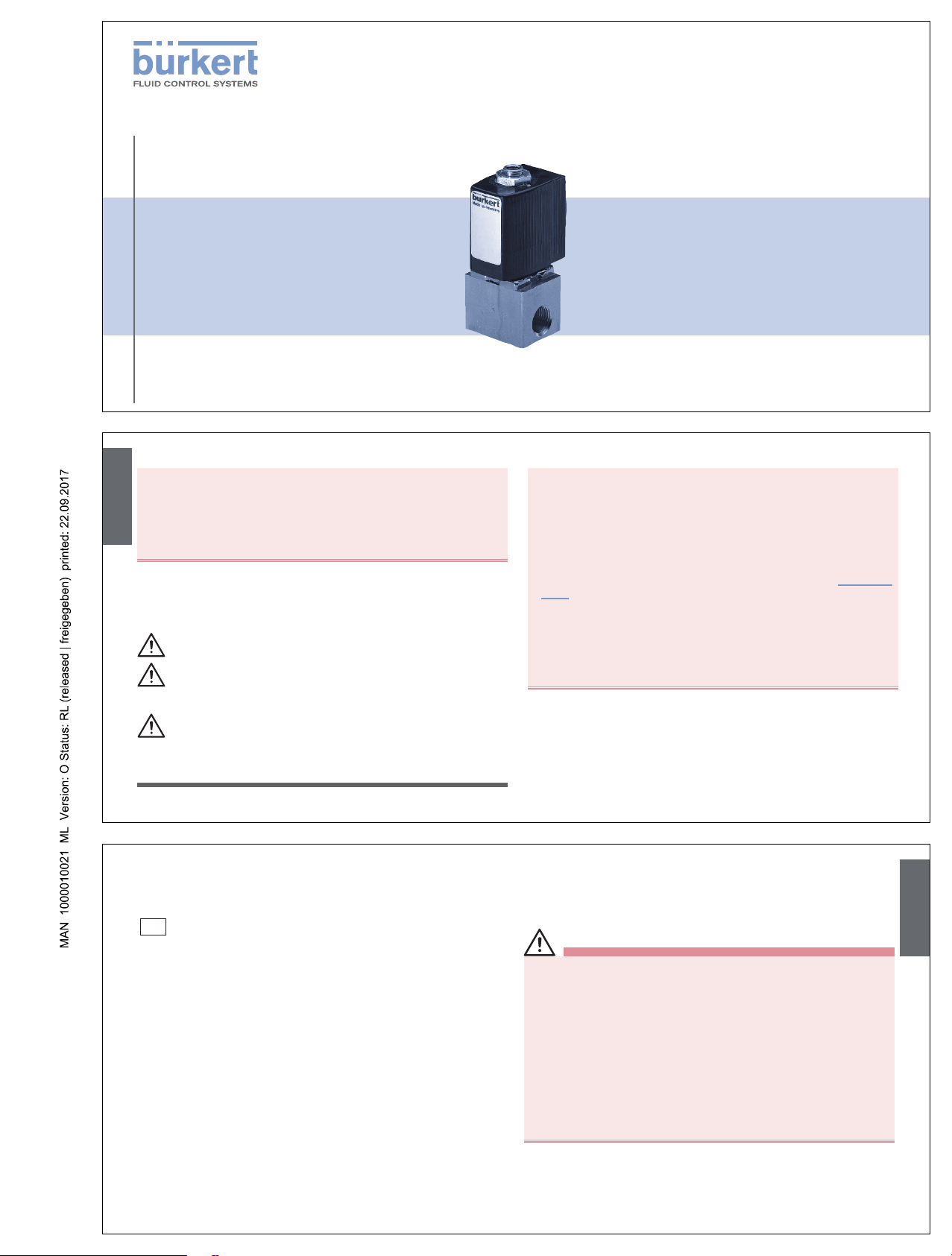
Type 6012
3/2-Way Mini Solenoid Valve
3/2-Wege-Mini-Magnetventil
Électrovanne mini à 3/2 voies
Address / Adresse
1. OPERATING INSTRUCTIONS
The operating instructions contain important information.
• Read the instructions carefully and follow the safety instructions in
particular, and also observe the operating conditions.
• Instructions must be available to each user.
• The liability and warranty for Type 6012 are void if the operating
instructions are not followed.
2. SYMBOLS
→ designates a procedure which you must carry out.
Warning of serious or fatal injuries:
DANGER!
In case of imminent danger.
WARNING!
In case of potential danger.
Warning of minor or moderately severe injuries:
CAUTION!
Warns of damage to property:
NOTE!
3. INTENDED USE
Incorrect use of the solenoid valve Type 6012 can be dangerous
to people, nearby equipment and the environment.
• The device is designed for blocking, dosing, filling and venting neutral
gaseous and liquid media.
• Do not use the device outdoors.
• Use according to the permitted data, operating conditions and conditions of use specified in the contract documents and operating
instructions. These are described in the chapter entitled “Technical
data”.
• The device may be used only in conjunction with third-party devices
and components recommended and authorised by Bürkert.
• Correct transportation, correct storage and installation and careful
use and maintenance are essential for reliable and problem-free
operation.
• Use the device only as intended.
3.1. Restrictions
If exporting the system/device, observe any existing restrictions.
english
4. BASIC SAFETY INSTRUCTIONS
These safety instructions do not make allowance for any contingencies and events which may arise during installation, operation and
maintenance.
Danger – high pressure!
• Before loosening the lines and valves, turn off the pressure and
vent the lines.
Risk of electric shock!
• Before reaching into the system, switch off the power supply and
secure to prevent reactivation!
• Observe applicable accident prevention and safety regulations for
electrical equipment!
Risk of burns/Risk of fire if used continuously through hot
device surface!
• Keep the device away from highly flammable substances and media
and do not touch with bare hands.
3.2. Approvals
The approval mark indicated on the Bürkert labels refers to the Bürkert
products.
e 1
03 5791
Devices which must bear the type approval mark were approved at the
Kraftfahrtbundesamt under the type approval number
e1*72/245*2006/96*5791*00
and are put into circulation with the indicated type approval mark. You
can obtain an extract of the type approval from the address below.
Bürkert Werke GmbH
Zulassungsbeauftragter,
Christian-Bürkert-Str. 13-17,
D-74653 Ingelfingen
english
Germany / Deutschland / Allemagne
Bürkert Fluid Control Systems
Sales Center
Christian-Bürkert-Str. 13-17
D-74653 Ingelfingen
Tel. + 49 (0) 7940 - 10 91 111
Fax + 49 (0) 7940 - 10 91 448
E-mail: info@de.buerkert.com
International
www.burkert.com → Bürkert → Company → Locations
Manuals and data sheets on the Internet:
www.burkert.com
Bedienungsanleitungen und Datenblätter im Internet:
www.buerkert.de
Manuel d'utilisation et fiches techniques sur Internet :
www.buerkert.fr
© 2013 Bürkert Werke GmbH & Co. KG, 2013 - 2017
Operating Instr uctions 1706/20_EU-EN_00803160 / Original DE
Page 2
General hazardous situations.
To prevent injury, ensure that:
• The solenoid valve Type 6012 is not to be used in areas where there
is a risk of explosion.
• Do not supply the medium connectors of the system with aggressive
or flammable mediums.
• Do not put any loads on the body (e.g. by placing objects on it or
standing on it).
• Do not make any external modifications to the device bodies. Do not
paint the body parts or screws.
• Installation and repair work may be carried out by authorized technicians only and with the appropriate tools.
• After an interruption in the power supply or pneumatic supply, ensure
that the process is restarted in a defined or controlled manner.
• The device may be operated only when in perfect condition and in
consideration of the operating instructions.
• The general rules of technology apply to application planning and
operation of the device.
5. SYSTEM DESCRIPTION
5.1. General description
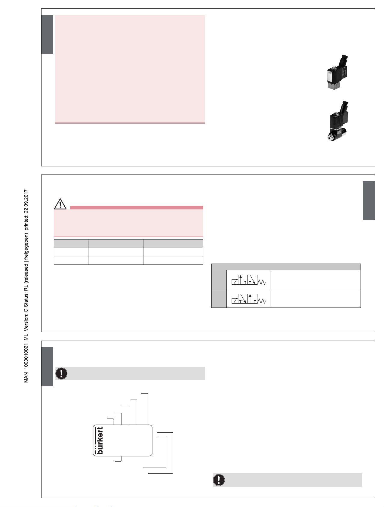
The direct-acting solenoid valve Type 6012 is available in two
designs.
Type 6012 is used for the blocking, dosing, filling
and venting of neutral gaseous and liquid media,
in particular for controlling single-acting pneumatic actuators or technical vacuum. The modular
designed valve can be installed individually or in a
block on the multiple manifold.
Type 6012P is used as a special pilot valve for
direct installation on the externally controlled
pneumatic actuators. It consists of the magnetic
actuator Type 6012 and a special connection
body with hollow screw which can be connected
directly to the control air connection of the
actuator. The valve features manual actuation as
standard.
english
6. TECHNICAL DATA
6.1. Operating conditions
WARNING!
Risk of injury!
Malfunction if used outside!
• Do not use Type 6012 outdoors and avoid heat sources which may
cause the allowable temperature range to be exceeded.
Type Ambient temperature Medium temperature
6012 -10 ... +55 °C -10 ... +100 °C
6012P -10 ... +40 °C -10 ... +60 °C
Media 6012: neutral gaseous and liquid media (e.g.
compressed air, Water, Hydraulic fluid, technical
Vacuum)
6012P: neutral gaseous media (e.g. compressed
air)
Viscosity max. 21 mm²/s
Protection class IP65 in accordance with EN 60529 with cable
plug
6.2. Conformity
In accordance with the EC Declaration of conformity, the solenoid valve
Type 6012 is compliant with the EC Directives.
6.3. Mechanical data
Dimensions See data sheet
Body material Type 6012: Brass, polyamide (PA),
Stainless steel 1.4305
Type 6012P: Polyamide (PA)
Hollow screw Type 6012P: Brass, nickel-plated
Sealing material FKM / EPDM
6.4. Fluidic data
Circuit functions
C
(NC)
2(A)
1(P)
3(R)
3/2-way valve, direct-acting, normal
output A unloaded
D
(NO)
2(B)
1(P)
3(R)
3/2-way valve, direct-acting, normal
output B pressurized
Pressure range 0 – 16 bar
english
Line connectors Type 6012: M5, G1/8, Flange
Type 6012P: G1/8, G1/4
Hose connector ∅ 6 mm
Note the voltage and current type as specified on the type
label.
6.5. Type label (Example)
Identifications number
Voltage, Frequency output
Nominal connection pressure
Type
Circuit function
Orifice
Sealing material
Body material
6012 C 1,0 FKM MS
Made in Germany
CE
00450000
WXXXX
230V 50Hz 2W
G1/8 PN 0
-
7 bar
6.6. Electrical data
Connections DIN EN 175301-803 Form C:
for cable plug Type 2506
DIN 43650 Form B:
for cable plug Type 2507
Wire connection on request
Power supply 24 V DC ± 10 % -
max. residual ripple 10%
24 V / 50 Hz
110 / 230 / 50 Hz
Voltage tolerance ± 10%
Nominal output 4 W
Nominal operating mode 100% continuous operation
for block installation:
2 W continuous operation on request
4 W intermittent operation 60%
(30 min)
Note the voltage and current type as specified on the type
label.
english
Page 3
7. INSTALLATION
7.1. Safety instructions
DANGER!
Risk of injury from high pressure in the equipment!
• Before loosening the lines and valves, turn off the pressure and
vent the lines.
Risk of injury due to electrical shock!
• Before reaching into the system, switch off the power supply and
secure to prevent reactivation!
• Observe applicable accident prevention and safety regulations for
electrical equipment!
WARNING!
Risk of injury from improper installation!
• Installation may be carried out by authorized technicians only and
with the appropriate tools!
Risk of injury from unintentional activation of the system and
an uncontrolled restart!
• Secure system from unintentional activation.
• Following installation, ensure a controlled restart.
7.2. Fluid installation
DANGER!
Risk of injury from high pressure in the equipment!
• Before loosening the lines and valves, turn off the pressure and
vent the lines.
Installation position: any, actuator preferably upwards.
Procedure:
→ Before installation, clean any possible dirt off the pipelines and
flange connections.
→ If required, install a dirt trap to prevent malfunctions. (Mesh size:
0.2 – 0.4 mm).
Pay attention to the flow direction of the valve!
from 1(P) → 2(A) (CF C) or
from 1(P) → 2(B) (CF D)
Body with threaded connection:
NOTE!
Caution risk of breakage!
• Do not use the coil as a lifting arm.
english
Use PTFE tape as sealing material.
→ Hold the device with a suitable tool (Open-end wrench) on the
body and screw into the pipeline.
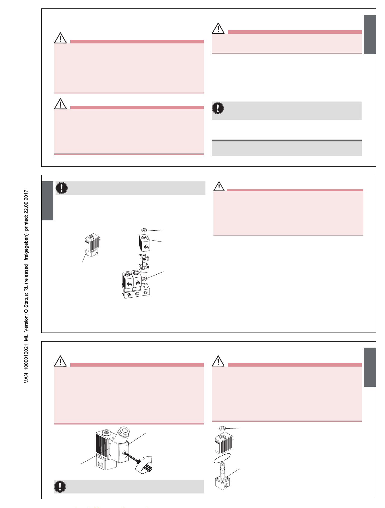
Valve with flanged connection:
Seal
Nut
Coil
Cover plate
→ Remove the cover plate.
→ Loosen the nut on the coil and remove coil.
WARNING!
Danger – escaping medium!
Leaking connections if seals not seated properly, if manifold uneven
or if surface quality of the manifold inadequate.
• Make certain the seals included with delivery are properly seated in
the valve.
• Ensure that the manifold is even.
• Ensure that the surface quality of the manifold is adequate.
→ Insert the seal into the valve.
→ Screw the body onto the manifold.
→ Attach the coil and screw on the nut (Tightening torque:
max. 2.8 Nm).
english
7.3. Electrical connection of the cable plug
WARNING!
Risk of injury due to electrical shock!
• Before reaching into the system, switch off the power supply and
secure to prevent reactivation!
• Observe applicable accident prevention and safety regulations for
electrical equipment!
If the protective conductor contact between the coil and body is
missing, there is danger of electrical shock!
• Always connect protective conductor.
• Check electrical continuity between coil and body.
max. 0.30 Nm
Type 2506
Seal
Note the voltage and current type as specified on the type
label.
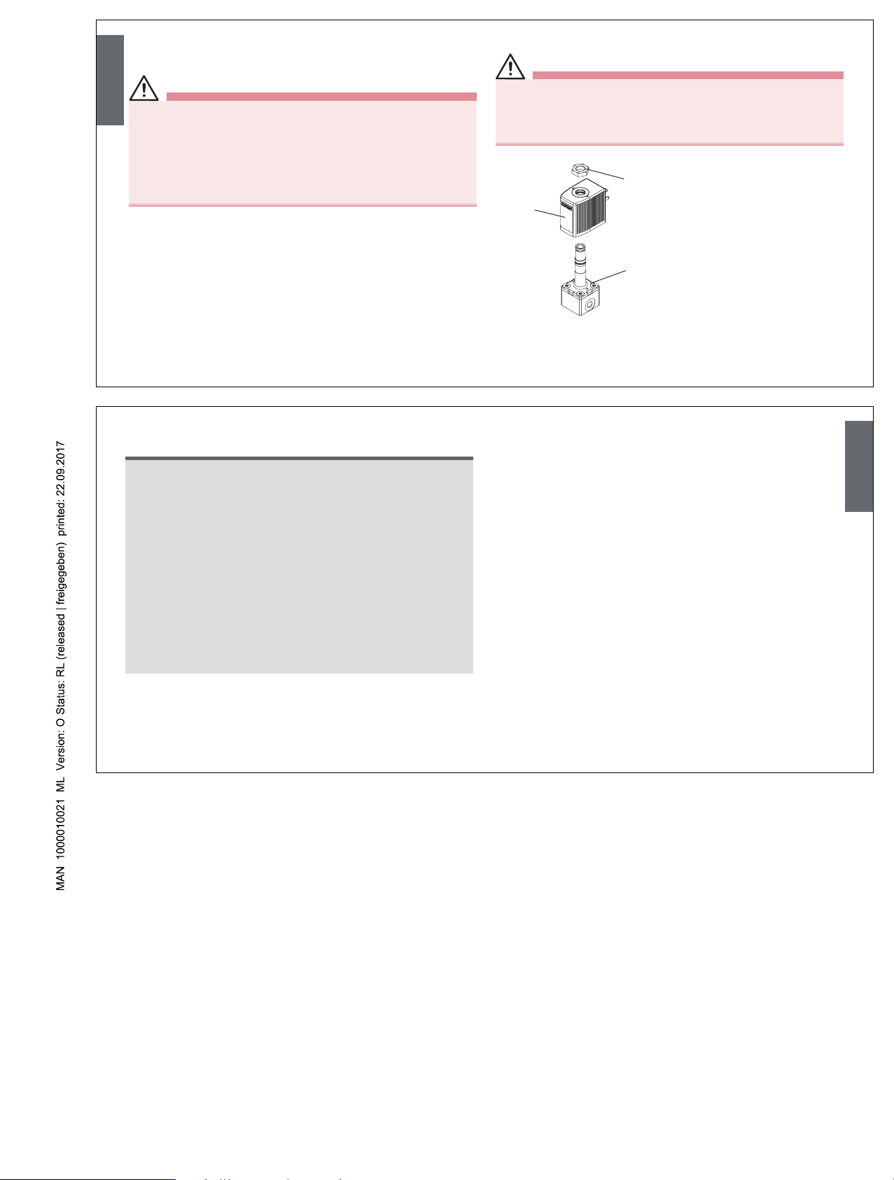
7.4. Installation of coil
WARNING!
Electric shock!
If the protective conductor contact between the coil and body is
missing, there is danger of electrical shock!
• Check protective conductor contact after installing the coil.
Overheating, Risk of fire!
Connection of the coil without pre-assembled valve will result in
overheating and destroy the coil.
• Connect the coil with assembled valve only.
4 x 90°
Nut
max. 2.8 Nm
O-ring
The coil can be turned by 4 x 90°:
→ Loosen nut.
→ Turn coil.
→ Tighten nut with suitable tool
(Open-end wrench) (max. 2.8
Nm).
english
Page 4
8. MAINTENANCE, TROUBLESHOOTING
8.1. Safety instructions
WARNING!
Risk of injury from improper maintenance!
• Maintenance may be carried out by authorized technicians only
and with the appropriate tools!
Risk of injury from unintentional activation of the system and
an uncontrolled restart!
• Secure system from unintentional activation.
• Following maintenance, ensure a controlled restart.
8.2. Malfunctions
If malfunctions occur, check:
→ the line connectors,
→ the operating pressure,
→ the power supply and valve control.
If the valve still does not switch, please contact your Bürkert Service.
9. SPARE PARTS
CAUTION!
Risk of injury and/or damage by the use of incorrect parts!
Incorrect accessories and unsuitable spare parts may cause injuries
and damage the device and the surrounding area.
• Use only original accessories and original spare parts from Bürkert.
Fitting
Coil
Nut
Coil and fitting can be ordered
complete by quoting the identification number of the device
(see type label).
Wearing part set on request.
english
10. TRANSPORT, STORAGE, DISPOSAL
NOTE!
Transport damages!
Inadequately protected equipment may be damaged during
transport.
• During transportation protect the device against wet and dirt in
shock-resistant packaging.
• Avoid exceeding or dropping below the allowable storage
temperature.
Incorrect storage may damage the device.
• Store the device in a dry and dust-free location!
• Storage temperature: -40 - 80 °C.
Damage to the environment caused by device components
contaminated with media.
• Observe applicable regulations on disposal and the environment.
english
Page 5

1. DIE BEDIENUNGSANLEITUNG
Die Bedienungsanleitung enthält wichtige Informationen.
• Die Bedienungsanleitung sorgfältig lesen und Hinweise zur Sicherheit beachten.
• Anleitung muss jedem Benutzer zur Verfügung stehen.
• Die Haftung und Gewährleistung für Typ 6012 entfällt, wenn die
Anweisungen der Bedienungsanleitung nicht beachtet werden.
2. DARSTELLUNGSMITTEL
→ markiert einen Arbeitsschritt den Sie ausführen müssen.
Warnung vor schweren oder tödlichen Verletzungen:
GEFAHR!
Bei unmittelbarer Gefahr.
WARNUNG!
Bei möglicher Gefahr.
Warnung vor leichten oder mittelschweren Verletzungen:
VORSICHT!
Warnung vor Sachschäden:
HINWEIS!
3. BESTIMMUNGSGEMÄSSER GEBRAUCH
Bei nicht bestimmungsgemäßem Einsatz des Magnetventils Typ
6012 können Gefahren für Personen, Anlagen in der Umgebung
und die Umwelt entstehen.
• Das Gerät ist zum Sperren, Dosieren, Füllen und Belüften von neutralen gasförmigen und flüssigen Medien konzipiert.
• Das Gerät nicht im Außenbereich einsetzen.
• Für den Einsatz die in den Vertragsdokumenten und der Bedienungsanleitung spezifizierten zulässigen Daten, Betriebs- und
Einsatzbedingungen beachten. Diese sind im Kapitel „Technische
Daten“ beschrieben.
• Das Gerät nur in Verbindung mit von Bürkert empfohlenen bzw.
zugelassenen Fremdgeräten und -komponenten einsetzen.
• Voraussetzungen für den sicheren und einwandfreien Betrieb sind
sachgemäßer Transport, sachgemäße Lagerung und Installation
sowie sorgfältige Bedienung und Instandhaltung.
• Das Gerät nur bestimmungsgemäß einsetzen.
3.1. Beschränkungen
Beachten Sie bei der Ausfuhr des Systems/Geräts gegebenenfalls
bestehende Beschränkungen.
deutsch
4. GRUNDLEGENDE
SICHERHEITSHINWEISE
Diese Sicherheitshinweise berücksichtigen keine Zufälligkeiten und
Ereignisse, die bei Montage, Betrieb und Wartung auftreten können.
Gefahr durch hohen Druck!
• Vor dem Lösen von Leitungen oder Ventilen den Druck abschalten
und Leitungen entlüften.
Gefahr durch elektrische Spannung!
• Vor Eingriffen in das Gerät oder die Anlage, Spannung abschalten
und vor Wiedereinschalten sichern!
• Die geltenden Unfallverhütungs- und Sicherheitsbestimmungen für
elektrische Geräte beachten!
Verbrennungsgefahr/Brandgefahr bei Dauerbetrieb durch heiße
Geräteoberfläche!
• Das Gerät von leicht brennbaren Stoffen und Medien fernhalten
und nicht mit bloßen Händen berühren.
3.2. Zulassungen
Die auf den Bürkert Typschildern aufgebrachte Zulassungskennzeichnung bezieht sich auf die Bürkert Produkte.
e 1
03 5791
Geräte, die das Typgenehmigungszeichen tragen müssen, wurden
beim Kraftfahrtbundesamt unter der Typgenehmigungsnummer
e1*72/245*2006/96*5791*00
genehmigt und werden mit dem gezeigten Typgenehmigungszeichen in
den Verkehr gebracht. Einen Auszug der Typgenehmigung erhalten Sie
unter der unten stehenden Adresse.
Bürkert Werke GmbH
Zulassungsbeauftragter,
Christian-Bürkert-Str. 13-17,
D-74653 Ingelfingen
deutsch
Allgemeine Gefahrensituationen.
Zum Schutz vor Verletzungen/Sachschaden beachten:
• Das Magnetventil Typ 6012 darf nicht in explosionsgefährdeten
Bereichen eingesetzt werden.
• In die Medienanschlüsse des Systems keine aggressiven oder
brennbaren Medien einspeisen.
• Das Gehäuse nicht mechanisch belasten (z.B. durch Ablage von
Gegenständen oder als Trittstufe).
• Keine äußerlichen Veränderungen an den Gerätegehäusen vornehmen. Gehäuseteile und Schrauben nicht lackieren.
• Nur geschultes Fachpersonal darf Installations- und Instandhaltungsarbeiten ausführen.
• Nach einer Unterbrechung der elektrischen oder pneumatischen
Versorgung für einen definierten oder kontrollierter Wiederanlauf
des Prozesses sorgen.
• Das Gerät nur in einwandfreiem Zustand und unter Beachtung der
Bedienungsanleitung betreiben.
• Für die Einsatzplanung und den Betrieb des Gerätes die allgemeinen Regeln der Technik einhalten.
5. SYSTEMBESCHREIBUNG
5.1. Allgemeine Beschreibung
Das direktwirkende Magnetventil Typ 6012 ist in zwei Ausführungen
verfügbar.
Typ 6012 wird zum Sperren, Dosieren, Füllen
und Belüften von neutralen gasförmigen und
flüssigen Medien verwendet, insbesondere zum
Steuern einfachwirkender Pneumatikantriebe oder
technisches Vakuum. Das modular aufgebaute
Ventil kann einzeln oder im Block auf Mehrfachanschlussplatte montiert werden.
Typ 6012P wird als spezielles Pilotventil zum
Direktanbau an fremdgesteuerte pneumatische
Antriebe verwendet. Es besteht aus dem Magnetantrieb vom Typ 6012 und einem speziellen
Anschlussgehäuse mit Hohlschraube, die direkt
an den Steuerluftanschluss des Antriebs angeschlossen werden kann. Das Ventil ist serienmäßig mit Handbetätigung ausgestattet.
deutsch
Page 6

6. TECHNISCHE DATEN
6.1. Betriebsbedingungen
WARNUNG!
Verletzungsgefahr!
Funktionsausfall bei Einsatz im Außenbereich!
• Typ 6012 nicht im Außenbereich einsetzen und Wärmequellen vermeiden, die zur Überschreitung des zulässigen Temperaturbereichs
führen können.
Typ Umgebungstempe-
ratur
Mediumstemperatur
6012 -10 ... +55 °C -10 ... +100 °C
6012P -10 ... +40 °C -10 ... +60 °C
Medien 6012: neutrale gasförmige und flüssige Medien (z. B.
Druckluft, Wasser, Hydrauliköl, technisches Vakuum)
6012P: neutrale gasförmige Medien
(z. B. Druckluft)
Viskosität max. 21 mm²/s
Schutzart IP65 nach EN 60529 mit Gerätesteckdose
6.2. Konformität
Das Magnetventil, Typ 6012 ist konform zu den EG-Richtlinien entsprechend der EG-Konformitätserklärung.
6.3. Mechanische Daten
Maße siehe Datenblatt
Gehäusematerial Typ 6012: Messing, Polyamid (PA),
Edelstahl 1.4305
Typ 6012P: Polyamid (PA)
Hohlschraube Typ 6012P : Messing, vernickelt
Dichtungsmaterial FKM / EPDM
6.4. Fluidische Daten
Wirkungsweisen
C
(NC)
2(A)
1(P)
3(R)
3/2 Wege-Ventil, direktwirkend,
stromlos Ausgang A entlastet
D
(NO)
2(B)
1(P)
3(R)
3/2 Wege-Ventil, direktwirkend,
stromlos Ausgang B druckbeaufschlagt
Druckbereich 0 ... 16 bar
deutsch
Leitungsanschlüsse Typ 6012: M5, G1/8, Flansch
Typ 6012P: G1/8, G1/4
Schlauchsteckverbinder
∅ 6 mm
Beachten Sie die auf dem Typschild angegebene Daten für
Spannung, Stromart und Druck.
6.5. Typschild (Beispiel)
Ident-Nr.
Spannung-Frequenz-Leistung
Anschluss-Nenndruck
Typ
Wirkungsweise
Nennweite
Dichtwerkstoff
Gehäusewerkstoff
6012 C 1,0 FKM MS
Made in Germany
CE
00450000
WXXXX
230V 50Hz 2W
G1/8 PN 0
-
7 bar
6.6. Elektrische Daten
Anschlüsse DIN EN 175301-803 Form C:
für Gerätesteckdose Typ 2506
DIN 43650 Form B:
für Gerätesteckdose Typ 2507
Litzenanschluss auf Anfrage
Spannungsversorgung 24 V DC ± 10 % -
max. Restwelligkeit 10 %
24 V / 50 Hz
110 / 230 / 50 Hz
Spannungstoleranz ± 10 %
Nennleistung 4 W
Nennbetriebsart Dauerbetrieb, ED 100 %
bei Blockmontage:
2 W Dauerbetrieb a. A.
4 W Aussetzbetrieb 60 %
(30 min)
Beachten Sie die auf dem Typschild angegebene Daten für
Spannung, Stromart und Druck.
deutsch
7. INSTALLATION
7.1. Sicherheitshinweise
GEFAHR!
Verletzungsgefahr durch hohen Druck in der Anlage!
• Vor dem Lösen von Leitungen und Ventilen den Druck abschalten
und Leitungen entlüften.
Verletzungsgefahr durch Stromschlag!
• Vor Eingriffen in das System die elektrische Spannung abschalten
und vor Wiedereinschalten sichern!
• Die geltenden Unfallverhütungs- und Sicherheitsbestimmungen für
elektrische Geräte beachten!
WARNUNG!
Verletzungsgefahr bei unsachgemäßer Installation!
• Die Installation darf nur autorisiertes Fachpersonal mit geeignetem
Werkzeug durchführen!
Verletzungsgefahr durch ungewolltes Einschalten der Anlage
und unkontrollierten Wiederanlauf!
• Anlage vor unbeabsichtigtem Betätigen sichern.
• Nach der Installation einen kontrollierten Wiederanlauf gewährleisten.
7.2. Fluidische Installation
GEFAHR!
Verletzungsgefahr durch hohen Druck in der Anlage!
• Vor dem Lösen von Leitungen und Ventilen den Druck abschalten
und Leitungen entlüften.
Einbaulage: beliebig, vorzugsweise Antrieb nach oben.
Vorgehensweise:
→ Vor der Montage Rohrleitungen und Flanschanschlüsse von even-
tuellen Verschmutzungen säubern.
→ Zum Schutz vor Störungen gegebenenfalls einen Schmutzfänger
einbauen (Maschenweite: 0,2 ... 0,4 mm).
Durchflussrichtung des Ventils beachten!
von 1(P) → 2(A) (WW C) oder
von 1(P) → 2(B) (WW D)
Gehäuse mit Gewindeanschluss:
HINWEIS!
Vorsicht Bruchgefahr!
• Die Spule darf nicht als Hebelarm benutzt werden.
deutsch
Page 7

Als Dichtungsmaterial PTFE-Band verwenden.
→ Das Gerät mit einem Gabelschlüssel am Gehäuse festhalten und
in die Rohrleitung einschrauben.
Ventil mit Flanschanschluss:
Dichtung
Mutter
Spule
Verschlussplatte
→ Verschlussplatte entfernen.
→ Mutter der Spule lösen und Spule demontieren.
WARNUNG!
Gefahr durch Mediumsaustritt!
Undichte Anschlüsse bei ungenauem Sitz der Dichtungen, bei
unebener Anschlussplatte oder unzureichender Oberflächengüte der
Anschlussplatte.
• Achten Sie bei den mitgelieferten Dichtungen auf den richtigen Sitz
im Ventil.
• Achten Sie auf die Ebenheit der Anschlussplatte.
• Achten Sie auf ausreichende Oberflächengüte der Anschlussplatte.
→ Dichtung in das Ventil einlegen.
→ Gehäuse auf die Anschlussplatte schrauben.
→ Spule aufstecken und die Mutter befestigen
(Anziehdrehmoment: max. 2,8 Nm).
deutsch
7.3. Elektrischer Anschluss der Gerätesteckdose
WARNUNG!
Verletzungsgefahr durch Stromschlag!
• Vor Eingriffen in das System die elektrische Spannung abschalten
und vor Wiedereinschalten sichern!
• Die geltenden Unfallverhütungs- und Sicherheitsbestimmungen für
elektrische Geräte beachten!
Bei fehlendem Schutzleiterkontakt zwischen Spule und Gehäuse
besteht die Gefahr des Stromschlags!
• Schutzleiter immer anschließen.
• Elektrischer Durchgang zwischen Spule und Gehäuse prüfen.
max. 0,30 Nm
Typ 2506
Dichtung
Spannung und Stromart laut Typschild beachten.
7.4. Spulenmontage
WARNUNG!
Stromschlag!
Bei fehlendem Schutzleiterkontakt zwischen Spule und Gehäuse
besteht die Gefahr des Stromschlags!
• Schutzleiterkontakt nach der Spulenmontage prüfen.
Überhitzung, Brandgefahr!
Der Anschluss der Spule ohne vormontiertes Ventil führt zur Überhitzung und zerstört die Spule.
• Spule nur mit montiertem Ventil anschließen.
4 x 90°
Mutter
max. 2,8 Nm
O-Ring
Die Spule kann um 4 x 90° verdreht
werden:
→ Mutter lösen.
→ Spule verdrehen.
→ Mutter mit einem Gabelschlüssel
festdrehen (max. 2,8 Nm).
deutsch
8. WARTUNG, FEHLERBEHEBUNG
8.1. Sicherheitshinweise
WARNUNG!
Verletzungsgefahr bei unsachgemäßen Wartungsarbeiten!
• Die Wartung darf nur autorisiertes Fachpersonal mit geeignetem
Werkzeug durchführen!
Verletzungsgefahr durch ungewolltes Einschalten der Anlage
und unkontrollierten Wiederanlauf!
• Anlage vor unbeabsichtigtem Betätigen sichern.
• Nach der Wartung einen kontrollierten Wiederanlauf gewährleisten.
8.2. Störungen
Bei Störungen überprüfen:
→ die Leitungsanschlüsse,
→ den Betriebsdruck,
→ die Spannungsversorgung und Ventilansteuerung.
Falls das Ventil dennoch nicht schaltet, wenden Sie sich bitte an Ihren
Bürkert-Service.
9. ERSATZTEILE
VORSICHT!
Verletzungsgefahr, Sachschäden durch falsche Teile!
Falsches Zubehör und ungeeignete Ersatzteile können Verletzungen
und Schäden am Gerät und dessen Umgebung verursachen.
• Nur Originalzubehör sowie Originalersatzteile der Firma Bürkert
verwenden.
Armatur
Spule
Mutter
Spule und Armatur können
komplett unter der Identnummer des Geräts bestellt
werden (siehe Typschild).
Verschleißteilsatz auf Anfrage.
deutsch
Page 8

10. TRANSPORT, LAGERUNG,
ENTSORGUNG
HINWEIS!
Transportschäden!
Unzureichend geschützte Geräte können durch den Transport
beschädigt werden.
• Gerät vor Nässe und Schmutz geschützt in einer stoßfesten Verpackung transportieren.
• Eine Über- bzw. Unterschreitung der zulässigen Lagertemperatur
vermeiden.
Falsche Lagerung kann Schäden am Gerät verursachen.
• Gerät trocken und staubfrei lagern!
• Lagertemperatur: -40 … +80 °C
Umweltschäden durch von Medien kontaminierte Geräteteile.
• Gerät und Verpackung umweltgerecht entsorgen!
• Geltende Entsorgungsvorschriften und Umweltbestimmungen
einhalten.
deutsch
Page 9

1. MANUEL D’UTILISATION
Manuel d’utilisation contiennent des informations importantes.
• Lire attentivement ce manuel et respecter les consignes de
sécurité.
• Le manuel doit être à disposition de chaque utilisateur.
• Nous déclinons toute responsabilité et n’accordons aucune garantie
légale pour le type 6012 en cas de non-respect des instructions
figurant dans ce manuel d’utilisation.
2. SYMBOLES
→ identifie une opération que vous effectuer.
Mise en garde contre les blessures graves ou mortelles :
DANGER !
En cas de danger imminent.
AVERTISSEMENT !
En cas de danger possible.
Mise en garde contre les blessures légères ou moyennement graves :
PRUDENCE !
Met en garde contre des dommages matériels:
REMARQUE !
3. UTILISATION CONFORME
L’utilisation non conforme de l’électrovanne, type 6012 peut présenter des dangers pour les personnes, les installations proches
et l’environnement.
• L’appareil est conçu pour couper, doser, remplir et aérer les fluides
neutres gazeux et liquides.
• N’utilisez pas l’appareil à l’extérieur.
• Lors de l’utilisation, il convient de respecter les données et conditions
d’utilisation et d’exploitation admissibles spécifiées dans les instructions de service et dans les documents contractuels. Celles-ci sont
décrites au chapitre « Caractéristiques techniques ».
• L’appareil peut être utilisé uniquement en association avec les
appareils et composants étrangers recommandés et homologués
par Bürkert.
• Les conditions pour l’utilisation sûre et parfaite sont un transport,
un stockage et une installation dans les règles ainsi qu’une parfaite
utilisation et maintenance.
• Veillez à ce que l’utilisation de l’appareil soit toujours conforme.
3.1. Limitations
Lors de l’exportation du système/de l’appareil, veuillez respecter les
limitations éventuelles existantes.
français
4. CONSIGNES DE SÉCURITÉ
FONDAMENTALES
Ces consignes de sécurité ne tiennent pas compte des hasards et des
événements pouvant survenir lors du montage, de l’exploitation et de
l’entretien.
Danger dû à la haute pression.
• Avant de desserrer les conduites et les vannes, coupez la pression
et purgez l’air des conduites.
Danger présenté par la tension électrique.
• Avant d’intervenir dans le système, coupez la tension et empêchez
toute remise sous tension par inadvertance.
• Veuillez respecter les réglementations en vigueur pour les appareils électriques en matière de prévention des accidents ainsi
qu’en matière de sécurité.
Risque de brûlures/d’incendie en fonctionnement continu dû à
des surfaces d’appareils brûlantes.
• Tenez les substances et les fluides facilement inflammables à l’écart
de l’appareil et ne touchez pas ce dernier à mains nues.
3.2. Homologations
Le marquage d’homologation apposé sur les plaques signalétiques
Bürkert se rapporte aux produits Bürkert.
e 1
03 5791
Les appareils devant porter l’homologation ont été autorisés par l’office
fédéral sous le numéro
e1*72/245*2006/96*5791*00
et sont mis sur le marché avec cette homologation. Vous pouvez obtenir
un extrait de cette homologation à l’adresse mentionnée ci-dessous.
Bürkert Werke GmbH
Zulassungsbeauftragter,
Christian-Bürkert-Str. 13-17,
D-74653 Ingelfingen
français
Situations dangereuses d’ordre général.
Pour prévenir les blessures, respectez ce qui suit :
• L’électrovanne type 6012 ne doit pas être utilisée dans des zones
présentant des risques d’explosion.
• N’alimentez pas les raccords du système en fluides agressifs ou
inflammables.
• Ne soumettez pas le corps à des contraintes mécaniques (par ex.
pour déposer des objets ou en l’utilisant comme marche).
• N’apportez pas de modifications à l’extérieur du corps de l’appareil.
Ne laquez pas les pièces du corps et les vis.
• Les travaux d’installation et de maintenance doivent être effectués
uniquement par des techniciens qualifiés et habilités disposant de
l’outillage approprié.
• Après une interruption de l’alimentation électrique ou pneumatique,
un redémarrage défini ou contrôlé du processus doit être garanti.
• L’appareil doit être utilisé uniquement en parfait état et en respectant
les instructions de service.
• Les règles générales de la technique sont d’application pour planifier
l’utilisation et utiliser l’appareil.
5. DESCRIPTION DU SYSTÈME
5.1. Description générale
L’électrovanne à action directe type 6012 est disponible en deux
versions.
Le type 6012 est utilisé pour couper, doser,
remplir et aérer les fluides neutres gazeux et
liquides et en particulier pour commander des
actionneurs pneumatiques simple effet ou le vide
technique. La vanne modulaire peut être montée
seule ou dans un bloc sur des embases multiples.
Le type 6012P est utilisé comme vanne pilote
spéciale à monter directement sur des actionneurs pneumatiques à commande extérieure. Elle
est composée d’une électrovanne du type 6012
et d’un corps de raccordement spécial avec vis
creuse pouvant être raccordée directement sur
l’air de commande de l’actionneur. De série, la
vanne est dotée d’une commande manuelle.
français
Page 10

6. CARACTÉRISTIQUES TECHNIQUES
6.1. Conditions d’exploitation
AVERTISSEMENT !
Risque de blessures.
Panne lors de l’utilisation à l’extérieur.
• N’utilisez pas le type 6012 à l’extérieur et évitez les sources de chaleur
susceptibles d’entraîner un dépassement de la plage de température
admissible.
Type Température
ambiante
Température
du fluide
6012 -10 ... +55 °C -10 ... +100 °C
6012P -10 ... +40 °C -10 ... +60 °C
Fluides 6012: fluides neutres gazeux et liquides (par ex. Air
comprimé, eau, huile hydraulique, vide technique)
6012P: fluides neutres gazeux (par ex. Air comprimé)
Viscosité 21 mm²/s maxi
Type de protection IP65 selon EN 60529 avec prise d’appareil
6.2. Conformité
L‘électrovanne type 6012 est conforme aux directives CE sur la base
de la déclaration de conformité CE.
6.3. Caractéristiques mécaniques
Dimensions voir fiche technique
Matériau du corps Type 6012 : laiton, polyamide (PA),
acier inoxydable 1.4305
Type 6012P : polyamide (PA)
Vis creuse Type 6012P : laiton, nickelé
Matériau d’étanchéité FKM / NBR
6.4. Données fluidiques
Fonction
C
(NC)
2(A)
1(P)
3(R)
Vanne à 3/2 voies, à action directe,
sortie A normalement fermée
D
(NO)
2(B)
1(P)
3(R)
Vanne à 3/2 voies, à action directe,
sortie B normalement ouverte
Plage de pression 0 – 16 bar
français
Raccords de conduite Type 6012 : M5, G1/8, bride
Type 6012P : G1/8, G1/4 Connecteur enfichable
pour tuyau souple ∅ 6 mm
Respectez les données indiquées sur la plaque signalétique
pour la tension, le type de courant et la pression.
6.5. Plaque signalétique (Exemple)
N° ID
Tension-Fréquence-Puissance
Raccord-Pression nominale
Type
Fonction
Diamètre nominal
Matériau du joint
Matériau du corps
6012 C 1,0 FKM MS
Made in Germany
CE
00450000
WXXXX
230V 50Hz 2W
G1/8 PN 0
-
7 bar
6.6. Caractéristiques électriques
Raccordements DIN EN 175301-803 forme C :
pour prise d’appareil, type 2506
DIN 43650 forme B :
pour prise d’appareil, type 2507
Raccordement pour torons sur demande
Alimentation en tension 24 V DC ± 10 % -
ondulation résiduelle maxi 10 %
24 V / 50 Hz
110 / 230 / 50 Hz
Tolérance de tension ± 10 %
Puissance nominale 4 W
Mode opératoire nominal 100% fonctionnement continu
en montage dos à dos 2 W fonctionnement:
continu sur demande
4 W fonctionnement
intermittent 60 %
(30 min)
Respectez les données indiquées sur la plaque signalétique
pour la tension, le type de courant et la pression.
français
7. INSTALLATION
7.1. Consignes de sécurité
DANGER !
Risque de blessures dû à la présence de haute pression dans
l'installation.
• Avant de desserrer les conduites et les vannes, coupez la pression
et purgez l’air des conduites.
Risque de choc électrique.
• Avant d'intervenir dans le système, coupez la tension et empêchez
toute remise sous tension par inadvertance !
• Veuillez respecter les réglementations en vigueur pour les appareils
électriques en matière de prévention des accidents ainsi qu’en matière
de sécurité !
AVERTISSEMENT !
Risque de blessures dû à un montage non conforme.
• Le montage doit être effectué uniquement par un personnel qualifié
et habilité disposant de l’outillage approprié.
Risque de blessures dû à la mise en marche involontaire de l'installation et le redémarrage non contrôlé.
• Empêchez tout actionnement involontaire de l'installation.
• Garantissez un redémarrage contrôlé après le montage.
7.2. Installation fluide
DANGER !
Risque de blessures dû à la présence de haute pression dans
l'installation.
• Avant de desserrer les conduites et les vannes, coupez la pression
et purgez l’air des conduites.
Position de montage : au choix, de préférence avec l’actionneur vers
le haut.
Procédure à suivre :
→ Avant le montage, nettoyer la tuyauterie et les raccordements à
bride afin d’enlever les éventuelles saletés.
→ Installez éventuellement un collecteur de boues comme protection
contre les dysfonctionnements (Mailles : 0,2 ... 0,4 mm).
Respectez le sens du débit de la vanne :
de 1(P) → 2(A) (fonction C) ou de 1(P) → 2(B) (fonction D)
Corps avec raccord fileté :
REMARQUE !
Attention risque de rupture.
• La bobine ne doit pas être utilisée comme levier.
français
Page 11

Utilisez une bande PTFE comme matériau d’étanchéité.
→ Maintenez l’appareil sur le corps à l’aide d’un outil approprié (clé
à fourche) et vissez-le dans la tuyauterie.
Vanne avec raccord à bride :
Joint
Écrou
Bobine
Plaque de fermeture
→ Enlevez la plaque de fermeture.
→ Desserrez l’écrou de la bobine et démontez celle-ci.
AVERTISSEMENT !
Danger dû à la sortie de fluide.
Raccords non étanches dus à une mauvaise position des joints,
une plaque de raccordement non plane ou d’une qualité de surface
insuffisante.
• Veillez au positionnement correct des joints fournis dans la vanne.
• Veillez à la planéité de la plaque de raccordement.
• Veillez à une qualité de surface suffisante de la plaque de
raccordement.
→ Placez le joint dans la vanne.
→ Vissez le corps sur l’embase.
→ Mettez la bobine en place et serrez l’écrou (couple de serrage :
2,8 Nm maxi).
français
7.3. Raccordement électrique de la prise de
l’appareil
AVERTISSEMENT !
Risque de choc électrique.
• Avant d'intervenir dans le système, coupez la tension et empêchez
toute remise sous tension par inadvertance.
• Veuillez respecter les réglementations en vigueur pour les appareils
électriques en matière de prévention des accidents ainsi qu’en matière
de sécurité.
Il y a risque de choc électrique en l'absence d'un contact du conducteur
de protection entre la bobine et le corps.
• Raccordez toujours le conducteur de protection.
• Contrôlez le passage du courant entre la bobine et le corps.
max. 0,30 Nm
Type 2506
Joint
Respectez la tension et le type de courant selon la plaque
signalétique.
7.4. Montage de la bobine
AVERTISSEMENT !
Choc électrique.
Il y a risque de choc électrique en l’absence d’un contact du
conducteur de protection entre la bobine et le corps.
• Contrôlez le contact du conducteur de protection après montage
de la bobine.
Surchauffe, risque d’incendie.
Le raccordement de la bobine sans vanne en amont entraîne la surchauffe et la destruction de la bobine.
• Raccorder la bobine uniquement avec la vanne montée.
français
4 x 90°
Écrou
max. 2,8 Nm
Joint
La vanne peut être tournée 4 x 90° :
→ Desserrez l’écrou.
→ Tournez la bobine.
→ Serrez l’écrou à fond avec un
outil approprié (clé à fourche)
(2,8 Nm maxi).
8. MAINTENANCE, DÉPANNAGE
8.1. Consignes de sécurité
AVERTISSEMENT !
Risque de blessures dû à des travaux de maintenance non
conformes.
• La maintenance doit être effectué uniquement par un personnel
qualifié et habilité disposant de l’outillage approprié.
Risque de blessures dû à la mise en marche involontaire de l’installation et le redémarrage non contrôlé.
• Empêchez tout actionnement involontaire de l’installation.
• Garantissez un redémarrage contrôlé après la maintenance.
8.2. Pannes
En présence de pannes, vérifiez :
→ les raccords de conduite,
→ la pression de service,
→ l’alimentation en tension et la commande de la vanne.
Si malgré tout la vanne ne fonctionne pas, veuillez contacter votre
service après-vente Bürkert.
français
Page 12

9. PIÈCES DE RECHANGE
PRUDENCE !
Risque de blessures, de dommages matériels dus à de mauvaises pièces.
De mauvais accessoires ou des pièces de rechange inadaptées
peuvent provoquer des blessures et endommager l’appareil ou son
environnement.
• Utilisez uniquement des accessoires ainsi que des pièces de
rechange d’origine de la société Bürkert.
Robinetterie
Bobine
Écrou
La bobine et la robinetterie
peuvent être commandées
au complet sous le numéro
d’identification d’appareil
(voir plaque signalétique).
Jeu de pièces d’usure sur
demande
10. TRANSPORT, STOCKAGE, ÉLIMINATION
REMARQUE !
Dommages dus au transport.
Les appareils insuffisamment protégés peuvent être endommagés
pendant le transport.
• Transportez l’appareil à l’abri de l’humidité et des impuretés et
dans un emballage résistant aux chocs.
• Évitez le dépassement vers le haut ou le bas de la température de
stockage admissible.
Un mauvais stockage peut endommager l’appareil.
• Stockez l’appareil au sec et à l’abri des poussières !
• Température de stockage : -40 ... +80 °C.
Dommages à l’environnement causés par des pièces d’appareil contaminées par des fluides.
• Respectez les prescriptions en matière d’élimination des déchets
et de protection de l’environnement en vigueur.
français
www.burkert.com
 Loading...