

Page 1
Operating Instructions
LEVEL SWITCH 8110
- transistor (PNP)
With extended status indication
Page 2

Contents
1 About
this document
1.1 Function. . . . . . . . . . . . . . . . . . . . . . . . . . . . . . . . . .
3
1.2 Target group . . . . . . . . . . . . . . . . . . . . . . . . . . . . . .
3
1.3 Symbolism used. . . . . . . . . . . . . . . . . . . . . . . . . . . .
3
2 For your safety
2.1 Authorised personnel . . . . . . . . . . . . . . . . . . . . . . . .
4
2.2 Appropriate use . . . . . . . . . . . . . . . . . . . . . . . . . . . .
4
2.3 Warning about incorrect use . . . . . . . . . . . . . . . . . . .
4
2.4 General safety instructions . . . . . . . . . . . . . . . . . . . .
4
2.5 Safety label on the instrument . . . . . . . . . . . . . . . . . .
5
2.6 CE conformity . . . . . . . . . . . . . . . . . . . . . . . . . . . . .
5
3 Product description
3.1 Configuration . . . . . . . . . . . . . . . . . . . . . . . . . . . . . .
6
3.2 Principle of operation . . . . . . . . . . . . . . . . . . . . . . . .
7
3.3 Operation. . . . . . . . . . . . . . . . . . . . . . . . . . . . . . . . .
7
3.4 Storage and transport . . . . . . . . . . . . . . . . . . . . . . . .
8
4 Mounting
4.1 General instructions . . . . . . . . . . . . . . . . . . . . . . . . .
9
4.2 Instructions for installation. . . . . . . . . . . . . . . . . . . . .
11
5 Connecting to power supply
5.1 Preparing the connection . . . . . . . . . . . . . . . . . . . . .
13
5.2 Wiring plan. . . . . . . . . . . . . . . . . . . . . . . . . . . . . . . .
14
6 Setup
6.1 Indication of the switching status . . . . . . . . . . . . . . . .
18
6.2 Simulation . . . . . . . . . . . . . . . . . . . . . . . . . . . . . . . .
18
6.3 Function chart . . . . . . . . . . . . . . . . . . . . . . . . . . . . .
19
7 Maintenance and fault rectification
7.1 Maintenance . . . . . . . . . . . . . . . . . . . . . . . . . . . . . .
20
7.2 Rectify faults . . . . . . . . . . . . . . . . . . . . . . . . . . . . . .
20
8 Dismounting
8.1 Dismounting steps . . . . . . . . . . . . . . . . . . . . . . . . . .
21
8.2 Disposal . . . . . . . . . . . . . . . . . . . . . . . . . . . . . . . . .
21
9 Supplement
9.1 Technical data . . . . . . . . . . . . . . . . . . . . . . . . . . . . .
22
9.2 Dimensions . . . . . . . . . . . . . . . . . . . . . . . . . . . . . . .
26
Editing status: 2013-03-18
2 LEVEL
SWITCH 8110 • With extended status indication
Contents
41764-EN-130410
Page 3
1 About this document
1.1 Funct
ion
This operating instructions manual provides all the information you
need for mounting, connection and setup as well as important
instructions for maintenance and fault rectification. Please read this
information before putting the instrument into operation and keep this
manual accessible in the immediate vicinity of the device.
1.2 Target group
This operating instructions manual is directed to trained specialist
personnel. The contents of this manual should be made available to
these personnel and put into practice by them.
1.3 Symbolism used
Information, tip, note
Th
is symbol indicates helpful additional information.
Caution: If
this warning is ignored, faults or malfunctions can
result.
Warning: If this warning is ignored, injury to persons and/or serious
damage to the instrument can result.
Danger: If this warning is ignored, serious injury to persons and/or
destruction of the instrument can result.
Ex
applications
Th
is symbol indicates special instructions for Ex applications.
l List
The dot set in front indicates a list with no implied sequence.
à Action
This
arrow indicates a single action.
1 Sequence
Numbers set in front indicate successive steps in a procedure.
Battery disposal
Th
is symbol indicates special information about the disposal of
batteries and accumulators.
LEVEL SWITCH 8110 • With
extended status indication 3
1 About this document
41764-EN-130410
Page 4

2 For
your safety
2.1 Authorised personnel
All operations described in this operating instructions manual must be
carried out only by trained specialist personnel authorised by the plant
operator.
During work on and with the device the required personal protective
equipment must always be worn.
2.2 Appropriate use
The LEVEL SWITCH 8110 is a sensor for level detection.
You can find detailed information on the application range in chapter
"Product description".
Operational reliability is ensured only if the instrument is properly used
according to the specifications in the operating instructions manual as
well as possible supplementary instructions.
For safety and warranty reasons, any invasive work on the device
beyond that described in the operating instructions manual may be
carried out only by personnel authorised by the manufacturer. Arbitrary
conversions or modifications are explicitly forbidden.
2.3 Warning about incorrect use
Inappropriate or incorrect use of the instrument can give rise to
application-specific hazards, e.g. vessel overfill or damage to system
components through incorrect mounting or adjustment.
2.4 General safety instructions
This is a high-tech instrument requiring the strict observance of
standard regulations and guidelines. The user must take note of the
safety instructions in this operating instructions manual, the countryspecific installation standards as well as all prevailing safety
regulations and accident prevention rules.
The instrument must only be operated in a technically flawless and
reliable condition. The operator is responsible for trouble-free
operation of the instrument.
During the entire duration of use, the user is obliged to determine the
compliance of the necessary occupational safety measures with the
current valid rules and regulations and also take note of new
regulations.
4 LEVEL
SWITCH 8110 • With extended status indication
2 For your safety
41764-EN-130410
Page 5

2.5 Safety labe
l on the instrument
The safety approval markings and safety tips on the device must be
observed.
2.6 CE conformity
The device fulfills the legal requirements of the applicable EC
guidelines. By affixing the CE marking, we confirm successful testing
of the product.
You can find the conformity certificate in the download section of our
homepage.
LEVEL SWITCH 8110 • With
extended status indication 5
2 For your safety
41764-EN-130410
Page 6
3 Product description
3.1 Configur
ation
The scope of delivery encompasses:
l LEVEL SWITCH 8110 point level switch
l Test magnet
l Documentation
- this operating instructions manual
- if necessary, certificates
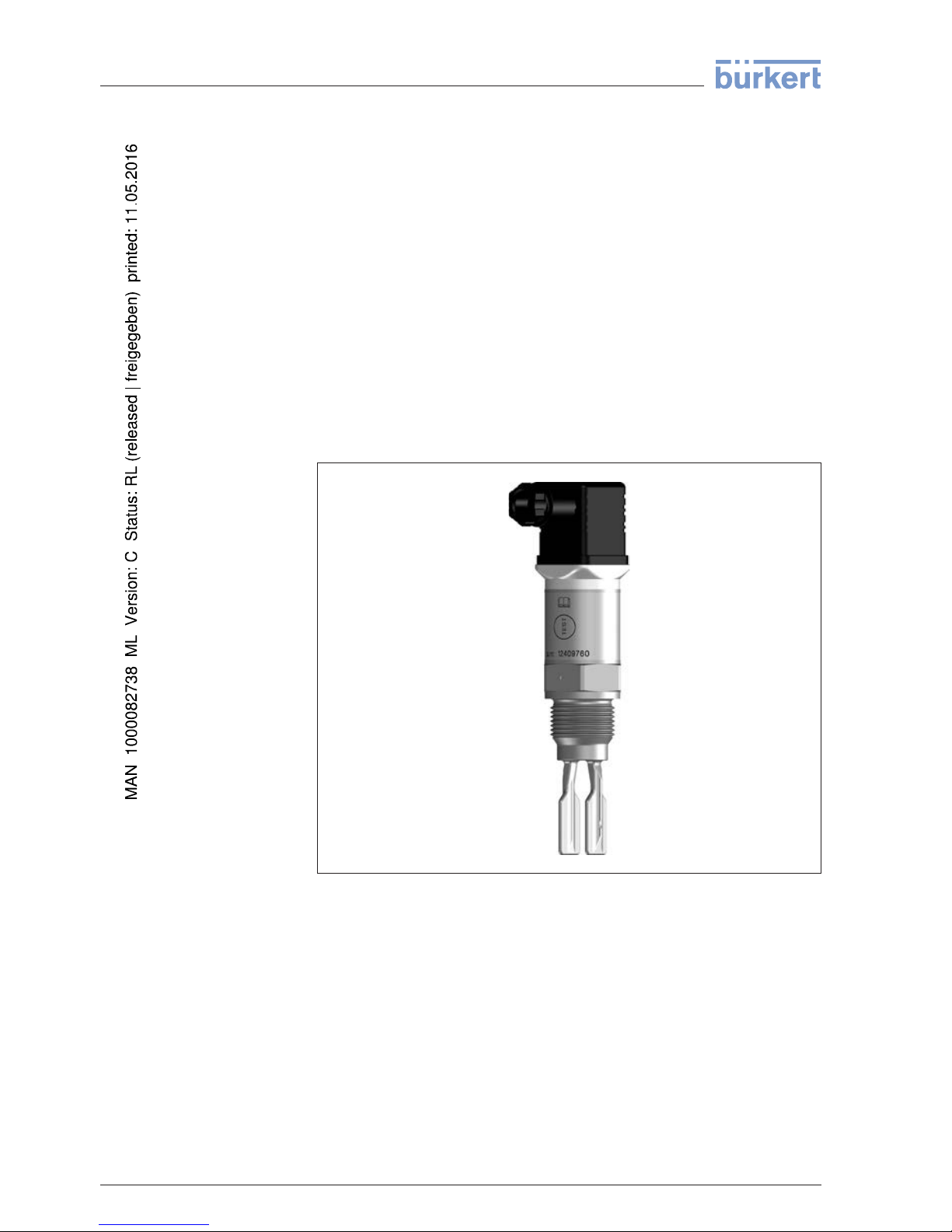
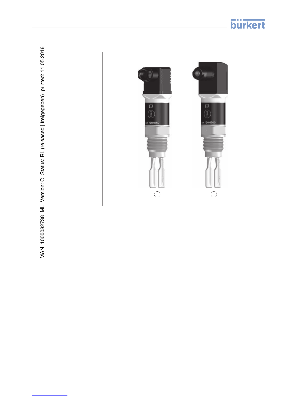
The LEVEL SWITCH 8110 consists of the components:
l Housing with electronics
l Process fitting with tuning fork
Fig. 1: LEVEL SWITCH 8110
Th
e nameplate contains the most important data for identification and
use of the instrument:
l Article number
l Serial number
l Technical data
l Article numbers, documentation
Sco
pe of delivery
Constituent parts
Type
plate
6 LEVEL
SWITCH 8110 • With extended status indication
3 Product description
41764-EN-130410
Page 7
3.2 Principle
of operation
LEVEL SWITCH 8110 is a point level sensor with tuning fork for level
detection.
It is designed for industrial use in all areas of process technology and
can be used in liquids.
Typical applications are overfill and dry run protection. With a tuning
fork of only 38 mm length, LEVEL SWITCH 8110 can be also mounted
e.g. in pipelines from DN 25. The small tuning fork allows use in
vessels, tanks and pipes. Thanks to its simple and robust measuring
system, LEVEL SWITCH 8110 is virtually unaffected by the chemical
and physical properties of the liquid.
It functions even under difficult conditions such as turbulence, air
bubbles, foam generation, buildup, strong external vibration or
changing products.
Function monitoring
The electronics module of LEVEL SWITCH 8110 continuously
monitors via frequency evaluation the following criteria:
l Strong corrosion or damage on the tuning fork
l Loss of vibration
l Line break to the piezo drive
If a malfunction is detected or in case of power failure, the electronics
takes on a defined switching condition, i.e. the output is open (safe
condition).
The tuning fork is piezoelectrically energised and vibrates at its
mechanical resonance frequency of approx. 1100 Hz. When the tuning
fork is submerged in the product, the frequency changes. This change
is detected by the integrated electronics module and converted into a
switching command.
LEVEL SWITCH 8110 is a compact instrument, i.e. it can be operated
without external evaluation system. The integrated electronics
evaluates the level signal and outputs a switching signal. With this
switching signal, a connected device can be operated directly (e.g. a
warning system, a pump etc.).
The data for power supply are specified in chapter "Technical data".
3.3 Operation
The switching status of LEVEL SWITCH 8110 can be checked with
closed housing (signal lamp). Products with a density > 0.7 g/cm³
(0.025 lbs/in³) can be detected.
Application area
Func
tional principle
Voltage supply
LEVEL SWITCH 8110 • With
extended status indication 7
3 Product description
41764-EN-130410
Page 8
3.4 Storage and transport
Your
instrument was protected by packaging during transport. Its
capacity to handle normal loads during transport is assured by a test
based on ISO 4180.
The packaging of standard instruments consists of environmentfriendly, recyclable cardboard. For special versions, PE foam or PE foil
is also used. Dispose of the packaging material via specialised
recycling companies.
Transport must be carried out under consideration of the notes on the
transport packaging. Nonobservance of these instructions can cause
damage to the device.
The delivery must be checked for completeness and possible transit
damage immediately at receipt. Ascertained transit damage or
concealed defects must be appropriately dealt with.
Up to the time of installation, the packages must be left closed and
stored according to the orientation and storage markings on the
outside.
Unless otherwise indicated, the packages must be stored only under
the following conditions:
l Not in the open
l Dry and dust free
l Not exposed to corrosive media
l Protected against solar radiation
l Avoiding mechanical shock and vibration
l Storage and transport temperature see chapter "Supplement -
Technical data - Ambient conditions"
l Relative humidity 20 … 85 %
Packag
ing
Transport
Transport inspection
Storage
Storage and transport
temp
era
ture
8 LEVEL
SWITCH 8110 • With extended status indication
3 Product description
41764-EN-130410
Page 9

4 Mounting
4.1 General
instructions
Make sure that all parts of the instrument coming in direct contact with
the process, especially the sensor element, process seal and process
fitting, are suitable for the existing process conditions, such as process
pressure, process temperature as well as the chemical properties of
the medium.
You can find the specifications in chapter "Technical data" and on the
nameplate.
In general, LEVEL SWITCH 8110 can be installed in any position. The
instrument only has to be mounted in such a way that the tuning fork is
at the height of the desired switching point.
Keep in mind that the swichting point can vary dependent on the
installation position.
The switching point refers to the medium water (1 g/cm³/0.036 lbs/in³).
Please keep in mind that the switching point of the instrument shifts
when the medium has a density differing from water.
2
3
1
11 mm
(0.43")
34 mm
(1.34")
Fig. 2: Mounting vertical
1 Switching
point in water
2 Switching point with lower density
3 Switching point with higher density
Suita
bility for the proc-
ess co
nditions
Switching point
LEVEL SWITCH 8110 • With
extended status indication 9
4 Moun
ting
41764-EN-130410
Page 10
2
1
Fig. 3: Mounting horizontal
1 Switching
point
2 Switching point (recommended mounting position, particularly for adhesive
products)
Use the recommended cables (see chapter "Connecting to power
supply") and tighten the cable gland.
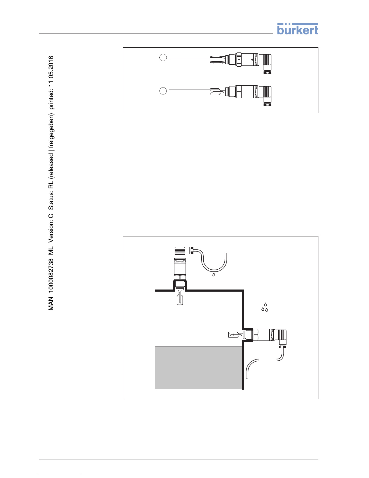
You can give your LEVEL SWITCH 8110 additional protection against
moisture penetration by leading the connection cable downward in
front of the cable entry. Rain and condensation water can thus drain
off. This applies mainly to outdoor mounting as well as installation in
areas where high humidity is expected (e.g. through cleaning
processes) or on cooled or heated vessels.
Fig. 4: Measures against
moisture penetration
Do not hold LEVEL SWITCH 8110 on the tuning fork.
Moisture
Transport
10 LEVEL
SWITCH 8110 • With extended status indication
4 Moun
ting
41764-EN-130410
Page 11
The process fitting
must be sealed if there is gauge or low pressure in
the vessel. Before use, check if the seal material is resistant against
the measured product and the process temperature.
The max. permissible pressure is specified in chapter "Technical data"
or on the type label of the sensor.
The vibrating level switch is a measuring instrument and must be
treated accordingly. Bending the vibrating element will destroy the
instrument.
Warning:
Th
e housing must not be used to screw the instrument in! Applying
tightening force can damage internal parts of the housing.
Use the hexagon above the thread for screwing in.
4.2 Instructions for installation
In case of horizontal mounting in adhesive and viscous products, the
surfaces of the tuning fork should be vertical in order to reduce buildup
on the tuning fork. The position of the tuning fork is indicated by a
marking on the hexagon of LEVEL SWITCH 8110. With this, you can
check the position of the tuning fork when screwing it in. When the
hexagon touches the seal, the thread can still be turned by approx. half
a turn. This is sufficient to reach the recommended installation
position.
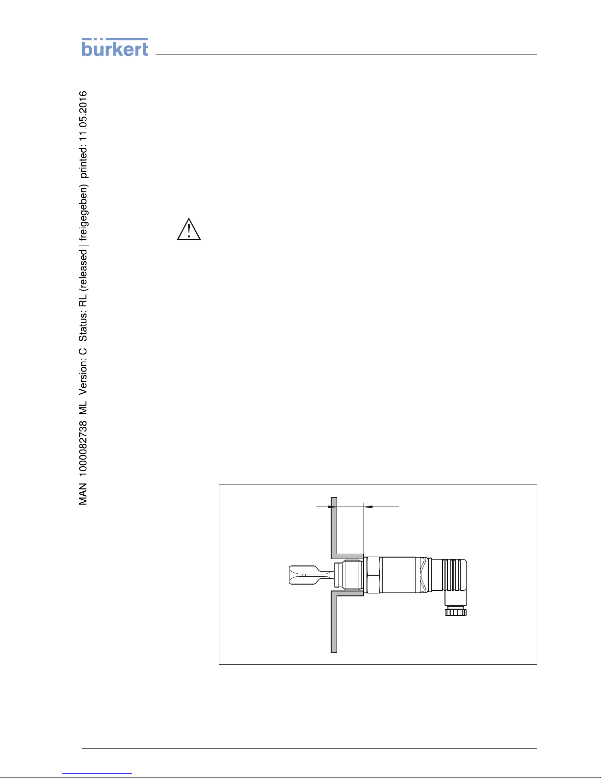
In adhesive and viscous products, the surfaces of the tuning fork
should protrude into the vessel to avoid buildup. Therefore sockets for
flanges and mountings bosses should not exceed a certain length.
30 mm
(1.18")
Fig. 5: Adhesive products
Press
ure/Vacuum
Handling
Adhesive
products
LEVEL SWITCH 8110 • With
extended status indication 11
4 Moun
ting
41764-EN-130410
Page 12

If LEVEL SWITCH 811
0 is mounted in the filling stream, unwanted
false measurement signals can be generated. For this reason, mount
LEVEL SWITCH 8110 at a position in the vessel where no
disturbances, e.g. from filling openings, agitators, etc., can occur.
To make sure the tuning fork of LEVEL SWITCH 8110 generates as
little resistance as possible to product flow, mount the sensor so that
the surfaces are parallel to the product movement.
Inflowing medium
Flows
12 LEVEL
SWITCH 8110 • With extended status indication
4 Moun
ting
41764-EN-130410
Page 13

5 Connecting to power supply
5.1 Prepa
ring the connection
Always keep in mind the following safety instructions:
l Connect only in the complete absence of line voltage
The instrument is connected with standard two-wire cable without
screen. If electromagnetic interference is expected which is above the
test values of EN 61326 for industrial areas, screened cable should be
used.
Use cable with round cross section. Depending on the plug
connection, you have to select the outer diameter of the cable
respectively so that the seal effect of the cable gland is ensured.
l Valve plug ISO 4400, ø 4.5 … 7 mm
l Valve plug ISO 4400 with IDC crimping technology, ø 5.5 … 8 mm
Use cable with a round wire cross section and tighten the cable gland.
When mounting outdoors, on cooled vessels or in moist areas in which
cleaning is made with steam or high pressure, the sealing of the cable
gland is very important.
Note
safety instructions
Connection cable
Cable glands
LEVEL SWITCH 8110 • With
extended status indication 13
5 Connecting to power supply
41764-EN-130410
Page 14
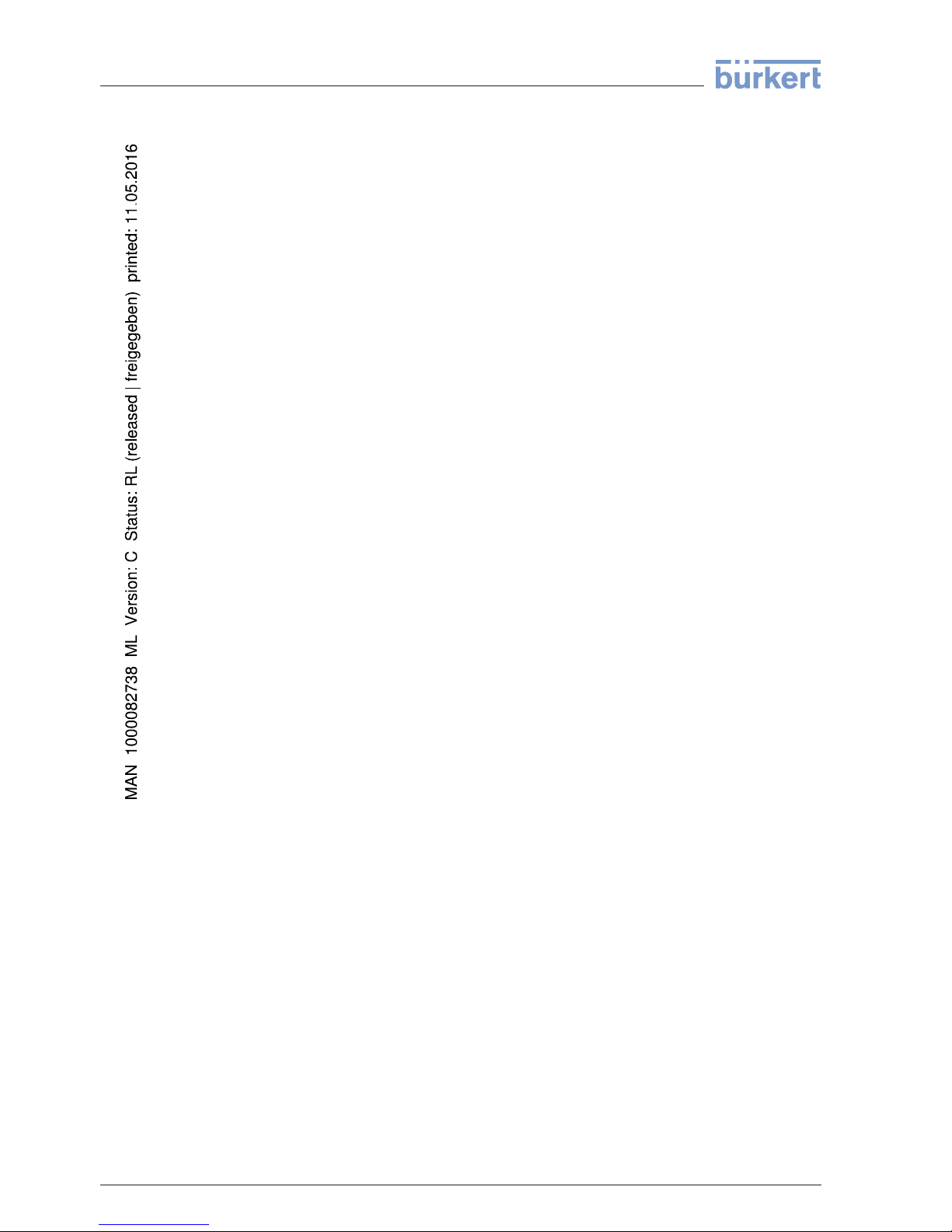
5.2 Wiring plan
1 2
Fig. 6: Overview of
the connection versions
1 M12 x 1 plug connection
2 Valve plug ISO 4400
3 Valve plug ISO 4400 with IDC method of termination
M12 x 1 plug connection
This plug connection requires a preconfectioned cable with plug.
Protection IP 66/IP 67.
Valve plug ISO 4400
For this plug version, standard cable with round wire cross-section can
be used. Cable diameter 4.5 … 7 mm, protection IP 65.
Housing overview
Plug
versions
14 LEVEL
SWITCH 8110 • With extended status indication
5 Connecting to power supply
41764-EN-130410
Page 15
1
4
5
6
7
8
9
10
2
3
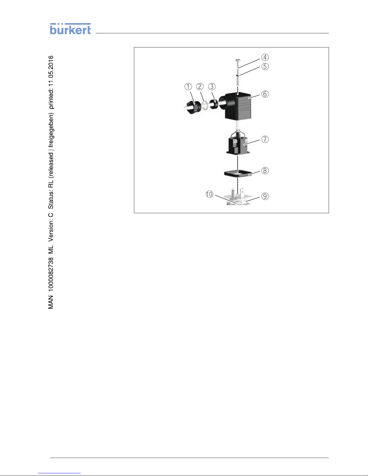
Fig. 7: Connection, valve plug ISO 4400
1 Pressure
screw
2 Pressure disc
3 Seal ring
4 Fixing screw
5 Seal washer
6 Plug housing
7 Plug insert
8 Profile seal
9 Control lamp
10 LEVEL SWITCH 8110
Valve plug ISO 4400 with IDC method of termination
For this plug version you can use standard cable with round wire
cross-section. The inner conductors do not have to be stripped. The
plug connects the conductors automatically when screwing in. Cable
diameter 5.5 … 8 mm, protection IP 67.
LEVEL SWITCH 8110 • With
extended status indication 15
5 Connecting to power supply
41764-EN-130410
Page 16
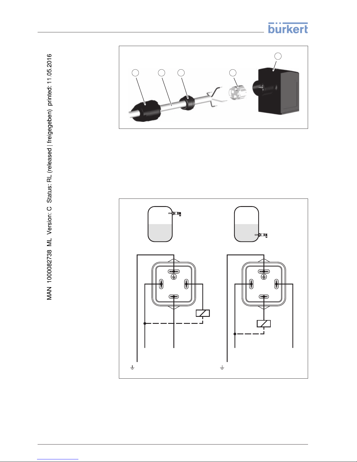
1 2 3 4
5
Fig. 8: Connection, valve plug ISO 4400 with IDC crimping
technology
1 Compression nut
2 Cable
3 Seal ring
4 Terminal insert
5 Plug housing
For connection to binary inputs of a PLC.
Max. Min.
3
21
3
21
- +
R
L
R
L
- +
PA
PA
Fig. 9: Wiring plan, Transistor
output with valve plug ISO 4400
PA Potential equalisation
RLLoad resistance (contactor, relay, etc.)
Transistor output
16 LEVEL
SWITCH 8110 • With extended status indication
5 Connecting to power supply
41764-EN-130410
Page 17
R
L
R
L
1
4
2
3
1
4
2
3
-
Max.
Min.
-
+
+
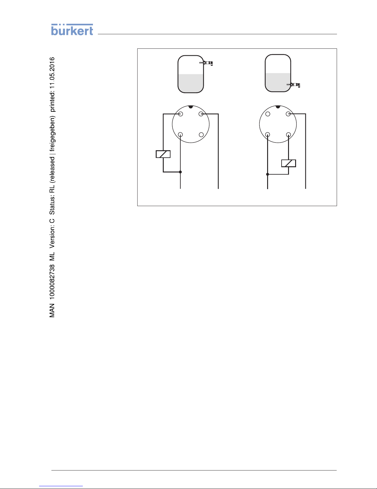
Fig. 10: Wiring plan (housing), transistor
output with M12 x 1 plug connection
1 Brown
2 White
3 Blue
4 Black
R
L
Load resistance (contactor, relay, etc.)
LEVEL SWITCH 8110 • With
extended status indication 17
5 Connecting to power supply
41764-EN-130410
Page 18

6 Setup
6.1 Indicati
on of the switching status
The switching status of the electronics can be checked via the signal
lamps (LEDs) integrated in the upper part of the housing.
The signal lamps have the following meaning:
l Green lights - voltage supply connected
l Yellow lights - vibrating element covered
l Red lights briefly - function test during instrument start (for 0.5 s)
l Red lights - shortcircuit or overload in the load circuit (sensor
output high-impedance)
l Red flashes - Error on the vibrating element or the electronics
(sensor output high impedance)
6.2 Simulation
The LEVEL SWITCH 8110 has an integrated function for simulation of
the output signal which can be activated magnetically. Please proceed
as follows:
à Hold the test magnet (accessory) against the circle symbol with
the label "TEST" on the instrument housing
Fig. 11: Simulation of
the output signal
The test magnet changes the current switching condition of the
instrument. You can check the change on the signal lamp. Please note
that all connected device are activated during the simulation.
If LEVEL SWITCH 8110 does not switch over after several tests with
the test magnet, you have to check the plug connection and the
connection cable and try it again. If there is no switching function, the
electronics will be defective. In this case you have to exchange the
electronics or return the instrument to our repair department.
18 LEVEL
SWITCH 8110 • With extended status indication
6 Setup
41764-EN-130410
Page 19
Caution:
It is
absolutely necessary that you remove the test magnet from the
instrument housing after the simulation.
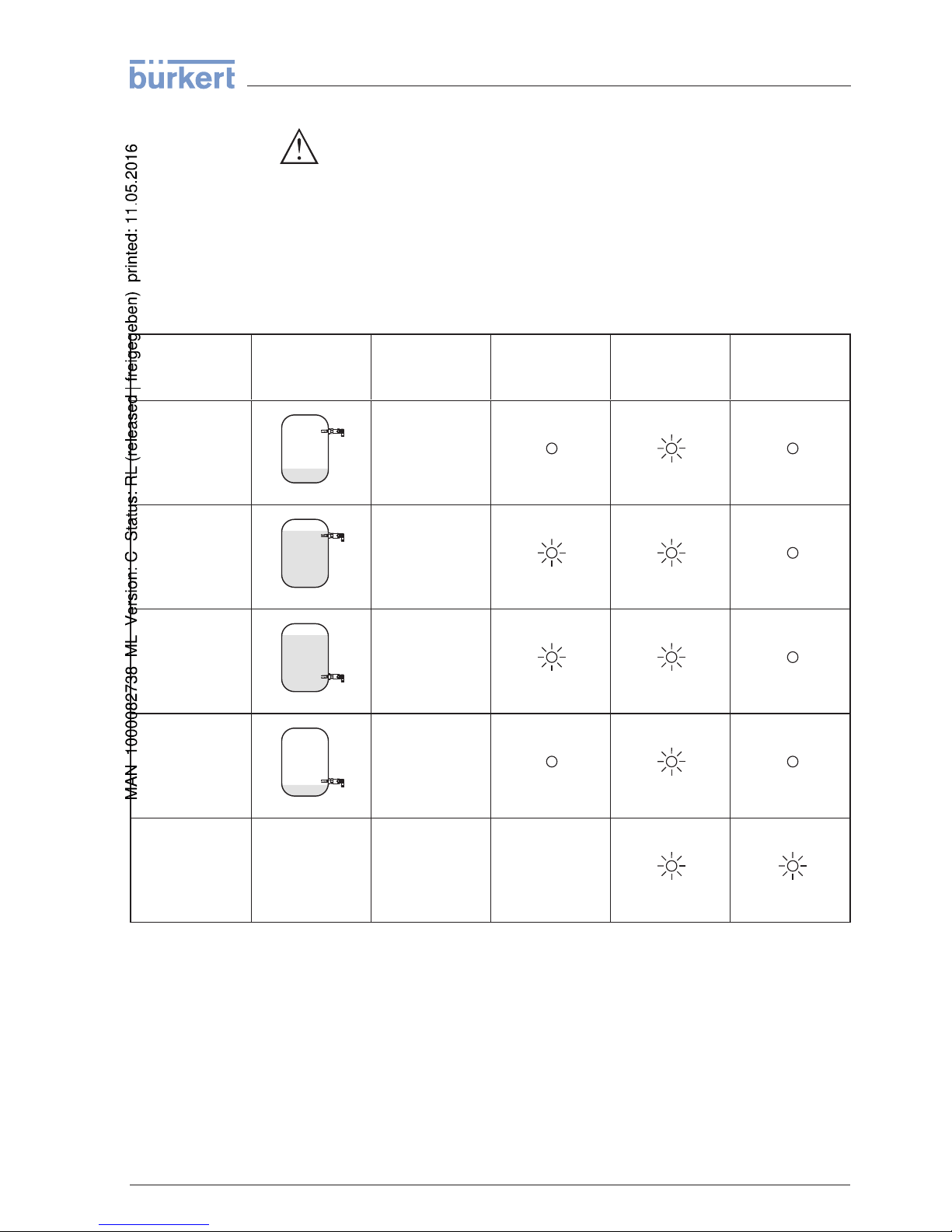
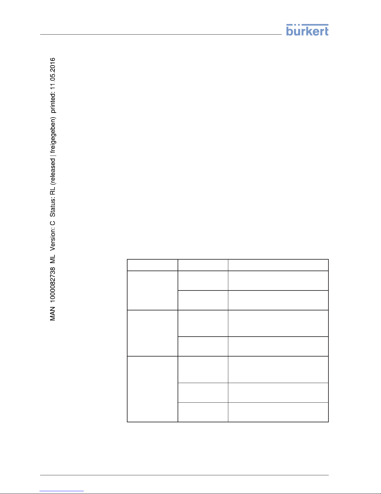
6.3 Function chart
The following chart provides an overview of the switching conditions
depending on the set mode and the level.
Level Switching sta-
tus
Control lamp
Yellow - cover-
age
Control
lamp
Green - voltage
indication
Control lamp
Red - fault sig-
nal
Mode max.
closed
Mode max. open
Mode min. closed
Mode
min.
open
Failure any open any
LEVEL SWITCH 8110 • With
extended status indication 19
6 Setup
41764-EN-130410
Page 20
7 Maintenance and fault rectification
7.1 Main
tenance
If the instrument is used properly, no special maintenance is required
in normal operation.
7.2 Rectify faults
The operator of the system is responsible for taking suitable measures
to rectify faults.
LEVEL SWITCH 8110 offers maximum reliability. Nevertheless, faults
can occur during operation. These may be caused by the following, e.
g.:
l Sensor
l Process
l Voltage supply
l Signal processing
The first measure to be taken is to check the output signal. In many
cases, the causes can be determined this way and the faults rectified.
Error Cause Rectification
Green signal lampoffVoltage
supply
interrupted.
Check the voltage supply and the
cable connection
Electronics defective
Exchange the instrument or send it in
for repair
Red signal lamp
lights (switching
output high-impedance)
Error with the
electrical connection
Connect the instrument according to
the wiring plan
Shortcircuit or
overload
Check the electrical connection
Red signal lamp
flashes (switching
output high-impedance)
Virbating frequency out of
specification
Check the vibrating element on buildup and remove it
Buildup on the vibrating element
Check the vibrating element and the
sensor if there is buildup and remove it
Vibrating element
damaged
Check if the vibrating element is
damage or extremely corroded
Depend
ing on the reason for the fault and the measures taken, the
steps described in chapter "Set up" may have to be carried out again.
Rea
ction when malfunc-
tions occu
r
Failure reasons
Fault rectification
Checking
the switching
signal
Reaction
after fault rec-
tificat
ion
20 LEVEL
SWITCH 8110 • With extended status indication
7 Mainte
nance and fault rectification
41764-EN-130410
Page 21
8 Dismounting
8.1 D
ismounting steps
Warning:
Before dismounting, be aware of dangerous process conditions such
as e.g. pressure in the vessel, high temperatures, corrosive or toxic
products etc.
Take note of chapters "Mounting" and "Connecting to power supply"
and carry out the listed steps in reverse order.
8.2 Disposal
The instrument consists of materials which can be recycled by
specialised recycling companies. We use recyclable materials and
have designed the parts to be easily separable.
WEEE directive 2002/96/EG
This instrument is not subject to the WEEE directive 2002/96/EG and
the respective national laws. Pass the instrument directly on to a
specialised recycling company and do not use the municipal collecting
points. These may be used only for privately used products according
to the WEEE directive.
Correct disposal avoids negative effects on humans and the environment and ensures recycling of useful raw materials.
Materials: see chapter "Technical data"
If you have no way to dispose of the old instrument properly, please
contact us concerning return and disposal.
LEVEL SWITCH 8110 • With
extended status indication 21
8 Dismounting
41764-EN-130410
Page 22
9 Supplement
9.1 Techn
ical data
General data
Material 316L corresponds to 1.4404 or 1.4435
Materials, wetted parts
- Tuning fork 316L
- Process seal Klingersil C-4400
- Process fittings 316L
Materials, non-wetted parts
- Housing 316L and plastic PEI
Weight approx. 250 g (9 oz)
Process fittings
- Pipe thread, cylindrical (DIN 3852-A) G½ A, G¾ A, G1 A
- American pipe thread, conical
(ASME B1.20.1)
½ NPT, ¾ NPT, 1 NPT
- hygienic fittings Clamp 1", Clamp 1½", Clamp 2" PN 16 DIN 32676,
ISO 2852/316L, bolting DN 25 PN 40, bolting DN 40
PN 40, bolting DN 50 PN 25, SMS DN 38 PN 6
Max. torque - process fitting
- Thread G½ A, ½ NPT 50 Nm (37 lbf ft)
- Thread G¾ A, ¾ NPT 75 Nm (55 lbf ft)
- Thread G1 A, 1 NPT 100 Nm (73 lbf ft)
Surface quality
- Standard R
a
< 3.2 µm (1.26-4in)
- Hygienic version R
a
< 0.8 µm (3.15-5in)
Measuring accuracy
Hysteresis approx. 2 mm (0.08 in) with vertical installation
Switching delay approx. 500 ms (on/off)
Measuring frequency approx. 1100 Hz
Ambient conditions
Ambient temperature on the housing -40 … +70 °C (-40 … +158 °F)
Storage and transport temperature -40 … +80 °C (-40 … +176 °F)
Process conditions
Process pressure -1 … 64 bar/-100 … 6400 kPa (-14.5 … 928 psig)
Process temperature - Standard -40 … +100 °C (-40 … +212 °F)
22 LEVEL
SWITCH 8110 • With extended status indication
9 Supplement
41764-EN-130410
Page 23
1
2
0°C
(32°F)
-20°C
(-4°F)
40°C
(104°F)
20°C
(68°F)
80°C
(176°F)
60°C
(140°F)
-40°C
(-40°F)
0°C
(32°F)
70°C
(158°F)
50°C
(122°F)
-40°C
(-40°F)
100°C
(212°F)
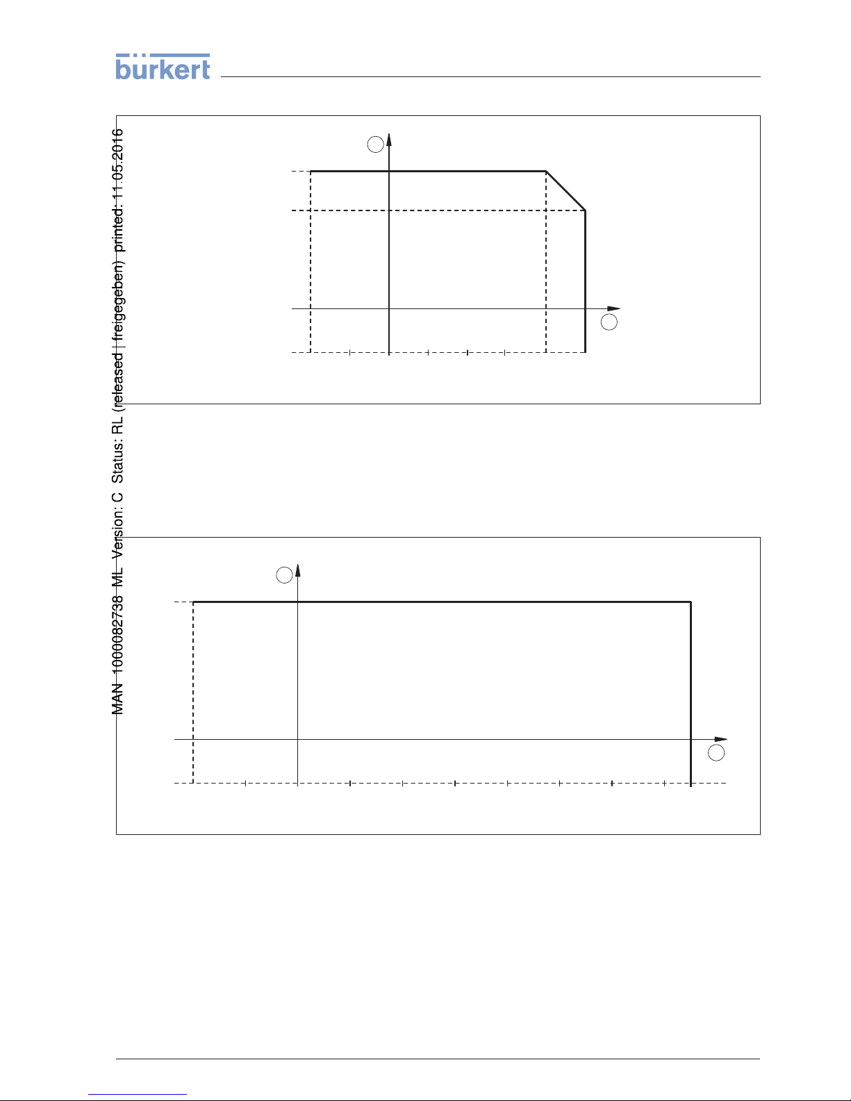
Fig. 30: Dependendency ambient
temperature to process temperature
1 Ambient temperature in °C (°F)
2 Process temperature in °C (°F)
Process temperature - High temperature
version (option)
-40 … +150 °C (-40 … +302 °F)
1
2
-40°C
(-40°F)
100°C
(212°F)
120°C
(248°F)
140°C
(284°F)
40°C
(104°F)
60°C
(140°F)
0°C
(32°F)
20°C
(68°F)
150°C
(302°F)
80°C
(176°F)
-20°C
(-4°F)
0°C
(32°F)
70°C
(158°F)
-40°C
(-40°F)
Fig. 31: Dependendency ambient
temperature to process temperature
1 Ambient temperature in °C (°F)
2 Process temperature in °C (°F)
Viscosity - dynamic 0.1 … 10000 mPa s
Flow velocity max. 6 m/s (with a viscosity of 10000 mPa s)
Density 0.7 … 2.5 g/cm³ (0.025 … 0.09 lbs/in³)
LEVEL SWITCH 8110 • With
extended status indication 23
9 Supplement
41764-EN-130410
Page 24
Operation
Plug
connections Specification see "Connecting to power supply"
Signal lamps (LED)
- Green Voltage supply on
- Yellow Vibrating element covered
- Red Failure
Output variable
Output Transistor output PNP
Load current max. 250 mA (output, permanently short-circuit
proof)
Voltage loss < 3 V
Switching voltage < 34 V DC
Blocking current < 10 µA
Mode
- Min./Max. Changeover by electronic connection
- Max. Overflow protection
- Min. Dry run protection
Voltage supply
Operating voltage 9.6 … 35 V DC
Power consumption max. 0.5 W
Electromechanical data
Valve plug ISO 4400
- Wire cross-section 1.5 mm² (0.06 in²)
- Outer cable diameter 4.5 … 7 mm (0.18 … 0.28 in)
Valve plug ISO 4400 with IDC method of termination
- Wire cross-section for wire cross-section of 0.5 … 1 mm²
(0.02 … 0.04 in²)
- Single-wire diameter > 0.1 mm (0.004 in)
- Wire diameter 1.6 … 2 mm² (0.06 … 0.08 in²)
- Outer cable diameter 5.5 … 8 mm (0.22 … 0.31 in)
- Connection frequency 10 x (on the same cross-section)
Electrical protective measures
Protection rating
- Valve plug ISO 4400 IP 65
- Valve plug ISO 4400 with IDC method of
termination
IP 67
- M12 x 1 plug connection IP 66/IP 67
24 LEVEL
SWITCH 8110 • With extended status indication
9 Supplement
41764-EN-130410
Page 25

Overvoltage category III
Protection class II
LEVEL SWITCH 8110 • With
extended status indication 25
9 Supplement
41764-EN-130410
Page 26
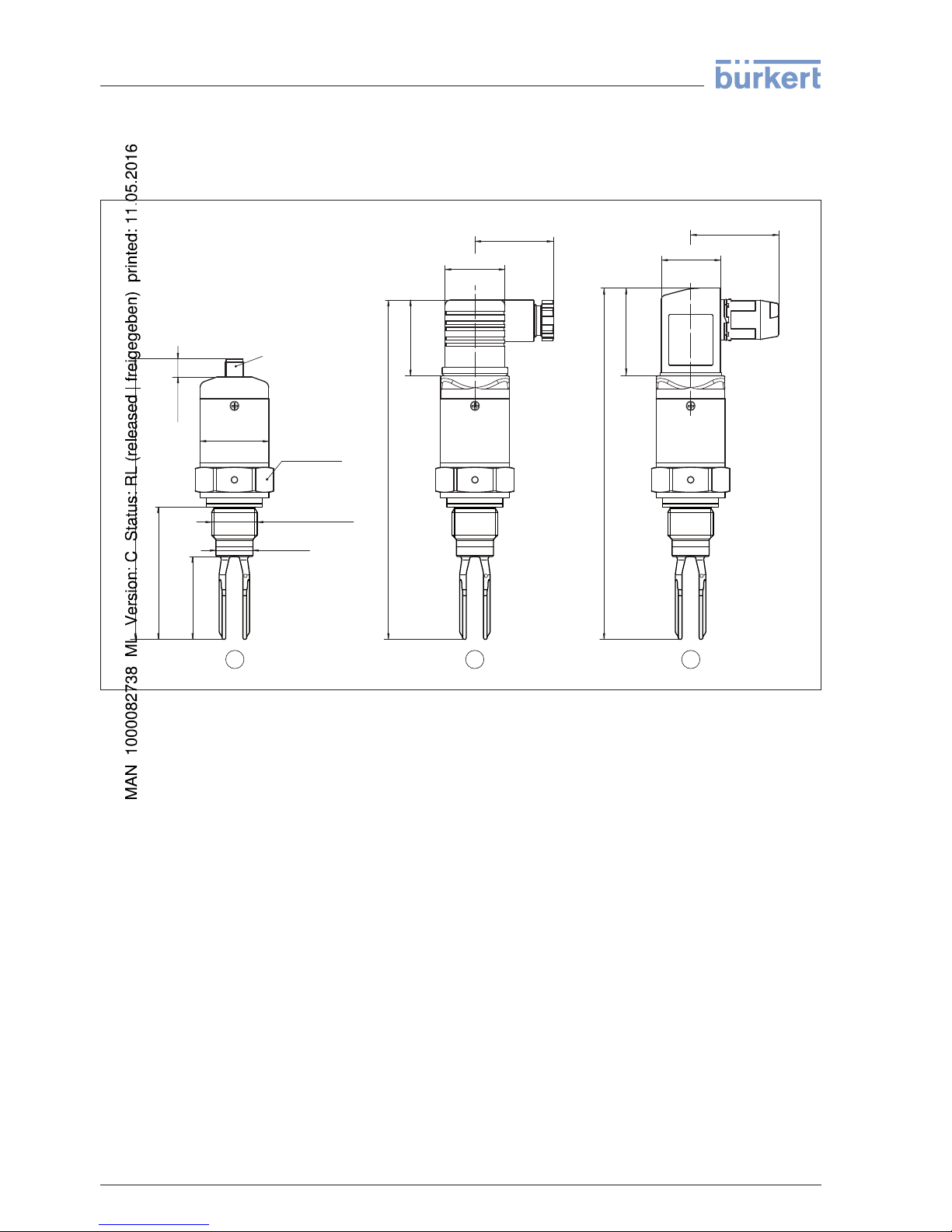
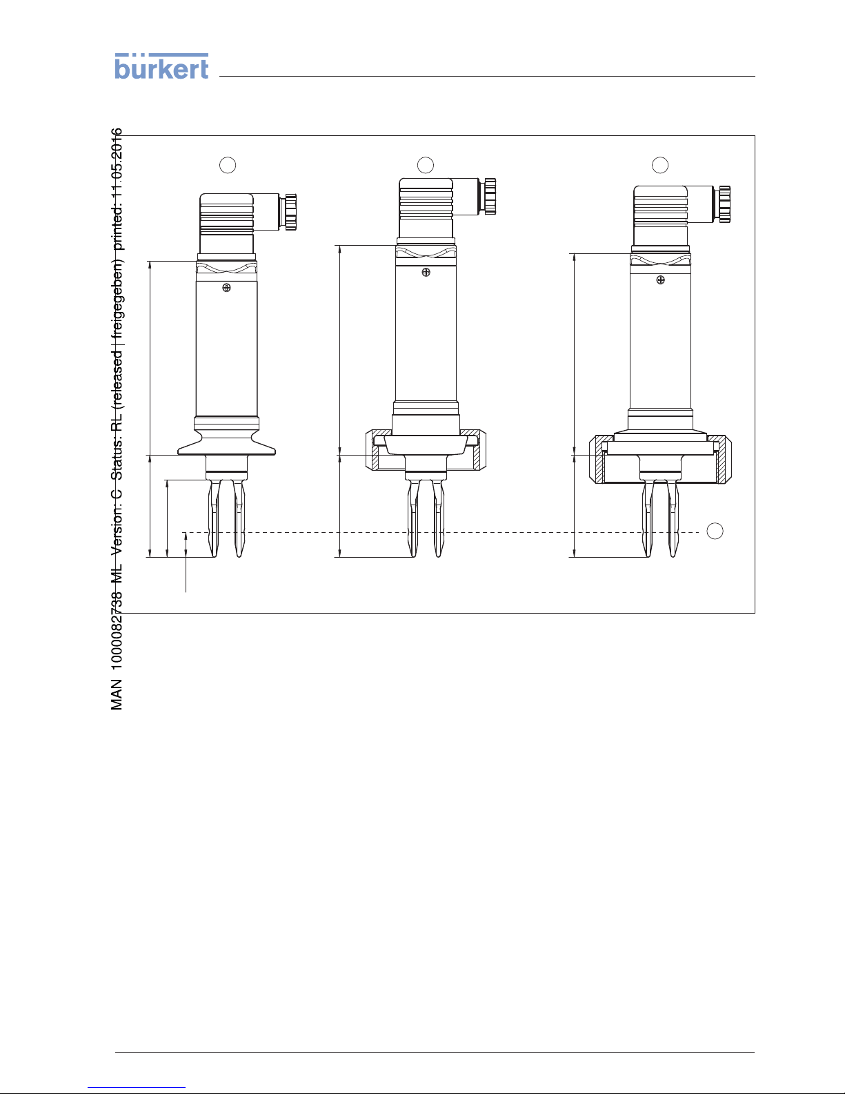
9.2 Dime
nsions
LEVEL SWITCH 8110, standard version - thread G½ A, ½ NPT
156 mm (6.14")
163 mm (6.42")
35 mm
(1.38")
42 mm
(1.65")
27 mm
(1.06")
SW 32 mm
(1.26")
36 mm
(1.42")
28 mm
(1.1")
38 mm
(1.5")
65 mm
(2.56")
10 mm
(0.39")
ø 31,7 mm
(1.25")
ø 17 mm
(0.67")
G1/2 A, 1/2" NPT
1 2 3
130,5 mm (5.14")
42 mm
(1.65")
M12 x 1
Fig. 32: LEVEL
SWITCH 8110, standard
version - thread G½ A, ½ NPT
1 Thread G½ A (DIN ISO 228/1), ½ NPT (M12 x 1)
1)
2 Thread G½ A (DIN ISO 228/1), ½ NPT (valve plug ISO 4400)
3 Thread G½ A (DIN ISO 228/1), ½ NPT (valve plug ISO 4400 with DC method of termination)
1)
Keepinmind
that the total length is extended by the plug connection.
26 LEVEL
SWITCH 8110 • With extended status indication
9 Supplement
41764-EN-130410
Page 27
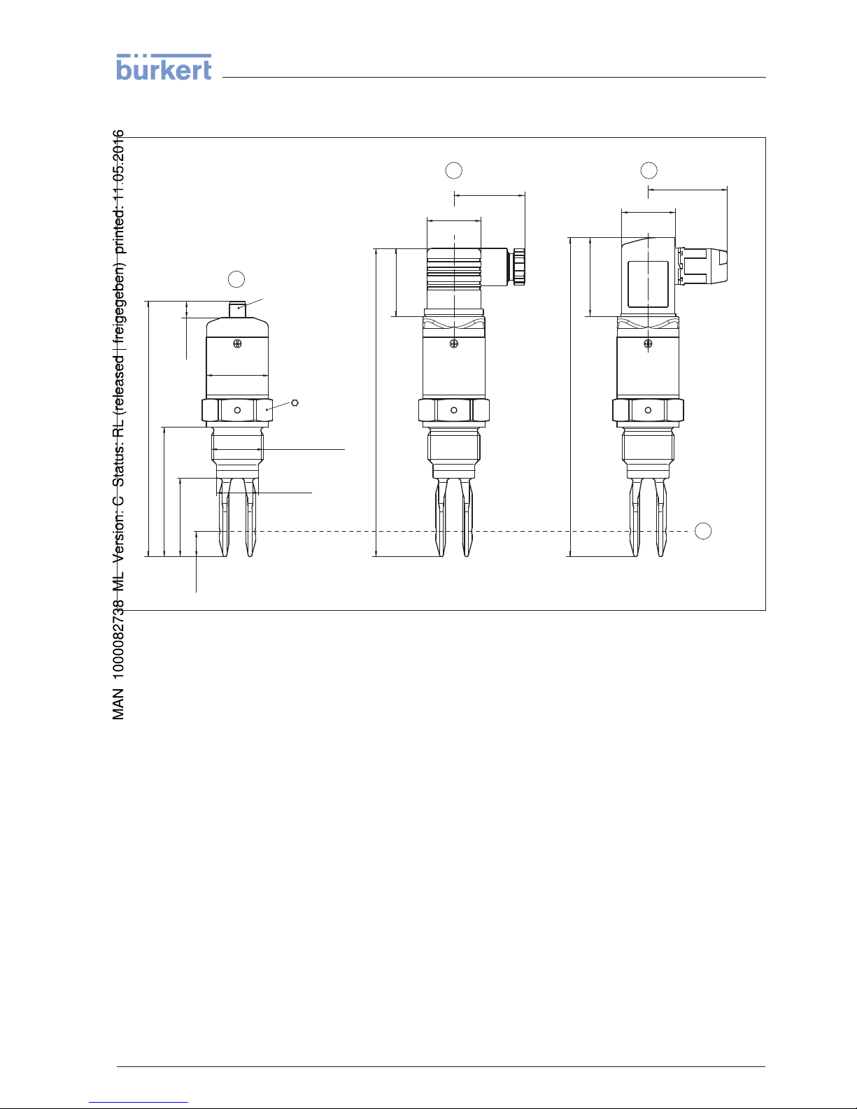
LEVEL SWITCH 8110, standard
version - thread G¾ A, G1 A / ¾ NPT, 1 NPT
158mm (6
7
/
32
")
165mm (6
1
/
2
")
35mm
(1
3
/
8
")
42mm
(1
21
/
32
")
27mm
(1 1/16")
36mm
(1 27/64")
28mm
(1 7/64")
L
40mm
(1
37
/
64
")
10mm
(
25
/
64
")
13mm
(
33
/
64
")
ø21,3mm
(27/32")
ø31,7mm
(1 1/4")
G3/4A, 3/4"NPT
G1A, 1"NPT
32
1
4
2
3
132,5mm (5
7
/
32
")
42mm
(1 21/32")
M12x1
Fig. 33: LEVEL
SWITCH 8110, standard
version - thread G¾ A, G1 A / ¾ NPT, 1 NPT
1 Thread G¾ A, G1 A (DIN ISO 228/1), ¾ NPT or 1 NPT (M12 x 1)
2)
2 Thread G¾ A, G1 A (DIN ISO 228/1), ¾ NPT or 1 NPT (valve plug ISO 4400)
3 Thread G¾ A, G1 A (DIN ISO 228/1), ¾ NPT or 1 NPT (valve plug ISO 4400 with IDC crimping technology)
4 Switching point
L Length with G¾ A, ¾ NPT: 66 mm (2.6 in)
L Length with G1 A, 1 NPT: 69 mm (2.7 in)
2)
Keep
in
mind
that the total length is extended by the plug connection.
LEVEL SWITCH 8110 • With
extended status indication 27
9 Supplement
41764-EN-130410
Page 28
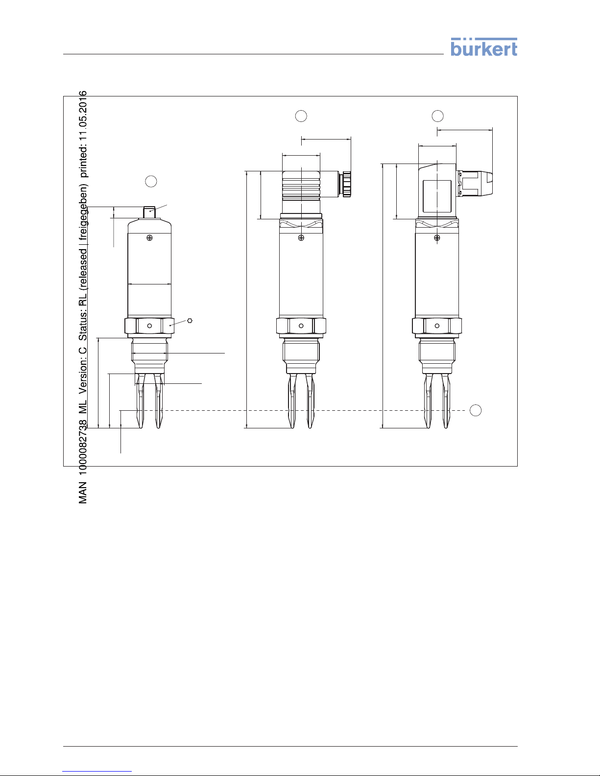
LEVEL SWITCH 8110, high
temperature version
162,5mm (6
25
/
64
")
188mm (7
13
/
32
")
182mm (7
11
/
64
")
35mm
(1
3
/
8
")
27mm
(1 1/16")
36mm
(1 27/64")
L
40mm
(1
37
/
64
")
13mm
(
33
/
64
")
ø21,3mm
(27/32")
ø31,7mm
(1 1/4")
G3/4A, 3/4"NPT
G1A, 1"NPT
32
1
4
2
3
42mm
(1
21
/
32
")
28mm
(1 7/64")
42mm
(1 21/32")
10mm
(
25
/
64
")
M12x1
Fig. 34: LEVEL SWITCH 8110, high
temperature version
1 Thread G¾ A, G1 A (DIN ISO 228/1), ¾ NPT or 1 NPT (M12 x 1)
3)
2 Thread G¾ A, G1 A (DIN ISO 228/1), ¾ NPT or 1 NPT (valve plug ISO 4400)
3 Thread G¾ A (DIN ISO 228/1), ¾ NPT or 1 NPT (valve plug ISO 4400 with IDC method of termination)
4 Switching point
L Length with G¾ A, ¾ NPT: 66 mm (2.6 in)
L Length with G1 A, 1 NPT: 69 mm (2.7 in)
3)
Keep
in mind
that the total length is extended by the plug connection.
28 LEVEL
SWITCH 8110 • With extended status indication
9 Supplement
41764-EN-130410
Page 29
LEVEL SWITCH 8110, hygienic
versions
~101 mm (3
31
/
32
")
4
L
2
1
3
~115 mm (7
13
/
32
")L
40 mm
(1
37
/
64
")
~105 mm (4
9
/
64
")L
13 mm
(
33
/
64
")
Fig. 35: LEVEL
SWITCH 8110, hygienic
versions
1 Clamp (valve plug ISO 4400)
2 Bolting (valve plug ISO 4400)
3 SMS 1145 (valve plug ISO 4400)
4 Switching point
L Length with Tri-Clamp: 53 mm (2.1 in)
L Length with bolting: 53 mm (2.1 in)
L Length with SMS 1145: 53 mm (2.1 in)
LEVEL SWITCH 8110 • With
extended status indication 29
9 Supplement
41764-EN-130410
Page 30

30 LEVEL
SWITCH 8110 • With extended status indication
9 Supplement
41764-EN-130410
Page 31

LEVEL SWITCH 8110 • With
extended status indication 31
9 Supplement
41764-EN-130410
Page 32

The smart choice
of Fluid Control Systems
www.burkert.com
41764-EN-130410
Page 33

Bedienungsanleitung
LEVEL SWITCH 8110
- Transistor (PNP)
Page 34

2
Inhaltsverzeichnis
LEVEL SWITCH 8110 • - Transistor (PNP)
41764-DE-130710
Inhaltsverzeichnis
1 Zu diesem Dokument
1.1 Funktion ........................................................................................................................... 3
1.2 Zielgruppe ........................................................................................................................ 3
1.3 Verwendete Symbolik ....................................................................................................... 3
2 Zu Ihrer Sicherheit
2.1 Autorisiertes Personal ...................................................................................................... 4
2.2 Bestimmungsgemäße Verwendung.................................................................................. 4
2.3 Warnung vor Fehlgebrauch .............................................................................................. 4
2.4 Allgemeine Sicherheitshinweise ....................................................................................... 4
2.5 Sicherheitskennzeichen am Gerät .................................................................................... 4
2.6 CE-Konformität ................................................................................................................. 5
3 Produktbeschreibung
3.1 Aufbau .............................................................................................................................. 6
3.2 Arbeitsweise ..................................................................................................................... 6
3.3 Bedienung ........................................................................................................................ 7
3.4 Lagerung und Transport ................................................................................................... 7
4 Montieren
4.1 Allgemeine Hinweise ........................................................................................................ 9
4.2 Montagehinweise ........................................................................................................... 11
5 An die Spannungsversorgung anschließen
5.1 Anschluss vorbereiten .................................................................................................... 13
5.2 Anschlussplan ................................................................................................................ 14
6 In Betrieb nehmen
6.1 Schaltzustandsanzeige .................................................................................................. 18
6.2 Simulation ...................................................................................................................... 18
6.3 Funktionstabelle ............................................................................................................. 19
7 Instandhalten und Störungen beseitigen
7.1 Wartung.......................................................................................................................... 20
7.2 Störungen beseitigen ..................................................................................................... 20
8 Ausbauen
8.1 Ausbauschritte ............................................................................................................... 21
8.2 Entsorgen ....................................................................................................................... 21
9 Anhang
9.1 Technische Daten ........................................................................................................... 22
9.2 Maße .............................................................................................................................. 25
Redaktionsstand: 2013-07-10
Page 35

3
1 Zu diesem Dokument
LEVEL SWITCH 8110 • - Transistor (PNP)
41764-DE-130710
1 Zu diesem Dokument
1.1 Funktion
Die vorliegende Betriebsanleitung liefert Ihnen die erforderlichen
Informationen für Montage, Anschluss und Inbetriebnahme sowie
wichtige Hinweise für Wartung und Störungsbeseitigung. Lesen
Sie diese deshalb vor der Inbetriebnahme und bewahren Sie sie
als Produktbestandteil in unmittelbarer Nähe des Gerätes jederzeit
zugänglich auf.
1.2 Zielgruppe
Diese Betriebsanleitung richtet sich an ausgebildetes Fachpersonal.
Der Inhalt dieser Anleitung muss dem Fachpersonal zugänglich
gemacht und umgesetzt werden.
1.3 Verwendete Symbolik
Information, Tipp, Hinweis
Dieses Symbol kennzeichnet hilfreiche Zusatzinformationen.
Vorsicht: Bei Nichtbeachten dieses Warnhinweises können Störun-
gen oder Fehlfunktionen die Folge sein.
Warnung: Bei Nichtbeachten dieses Warnhinweises kann ein Perso-
nenschaden und/oder ein schwerer Geräteschaden die Folge sein.
Gefahr: Bei Nichtbeachten dieses Warnhinweises kann eine ernst-
hafte Verletzung von Personen und/oder eine Zerstörung des Gerätes
die Folge sein.
Ex-Anwendungen
Dieses Symbol kennzeichnet besondere Hinweise für Ex-Anwendungen.
•
Liste
Der vorangestellte Punkt kennzeichnet eine Liste ohne zwingende
Reihenfolge.
→
Handlungsschritt
Dieser Pfeil kennzeichnet einen einzelnen Handlungsschritt.
1 Handlungsfolge
Vorangestellte Zahlen kennzeichnen aufeinander folgende Handlungsschritte.
Batterieentsorgung
Dieses Symbol kennzeichnet besondere Hinweise zur Entsorgung
von Batterien und Akkus.
Page 36

4
2 Zu Ihrer Sicherheit
LEVEL SWITCH 8110 • - Transistor (PNP)
41764-DE-130710
2 Zu Ihrer Sicherheit
2.1 Autorisiertes Personal
Sämtliche in dieser Betriebsanleitung beschriebenen Handhabungen
dürfen nur durch ausgebildetes und vom Anlagenbetreiber autorisiertes Fachpersonal durchgeführt werden.
Bei Arbeiten am und mit dem Gerät ist immer die erforderliche persönliche Schutzausrüstung zu tragen.
2.2 Bestimmungsgemäße Verwendung
Der LEVEL SWITCH 8110 ist ein Sensor zur Grenzstanderfassung.
Detaillierte Angaben zum Anwendungsbereich nden Sie im Kapitel
"Produktbeschreibung".
Die Betriebssicherheit des Gerätes ist nur bei bestimmungsgemäßer
Verwendung entsprechend den Angaben in der Betriebsanleitung
sowie in den evtl. ergänzenden Anleitungen gegeben.
Eingrie über die in der Betriebsanleitung beschriebenen Handhabungen hinaus dürfen aus Sicherheits- und Gewährleistungsgründen
nur durch vom Hersteller autorisiertes Personal vorgenommen werden. Eigenmächtige Umbauten oder Veränderungen sind ausdrücklich untersagt.
2.3 Warnung vor Fehlgebrauch
Bei nicht sachgerechter oder nicht bestimmungsgemäßer Verwen-
dung können von diesem Gerät anwendungsspezische Gefahren
ausgehen, so z. B. ein Überlauf des Behälters oder Schäden an
Anlagenteilen durch falsche Montage oder Einstellung.
2.4 Allgemeine Sicherheitshinweise
Das Gerät entspricht dem Stand der Technik unter Beachtung der
üblichen Vorschriften und Richtlinien. Durch den Anwender sind die
Sicherheitshinweise in dieser Betriebsanleitung, die landesspezischen Installationsstandards sowie die geltenden Sicherheitsbestimmungen und Unfallverhütungsvorschriften zu beachten.
Das Gerät darf nur in technisch einwandfreiem und betriebssicheren
Zustand betrieben werden. Der Betreiber ist für den störungsfreien
Betrieb des Gerätes verantwortlich.
Der Betreiber ist ferner verpichtet, während der gesamten Einsatzdauer die Übereinstimmung der erforderlichen Arbeitssicherheitsmaßnahmen mit dem aktuellen Stand der jeweils geltenden Regelwerke festzustellen und neue Vorschriften zu beachten.
2.5 Sicherheitskennzeichen am Gerät
Die auf dem Gerät angebrachten Sicherheitskennzeichen und -hinweise sind zu beachten.
Page 37

5
2 Zu Ihrer Sicherheit
LEVEL SWITCH 8110 • - Transistor (PNP)
41764-DE-130710
2.6 CE-Konformität
Das Gerät erfüllt die gesetzlichen Anforderungen der zutreenden
EG-Richtlinien. Mit dem CE-Zeichen bestätigen wir die erfolgreiche
Prüfung.
Die CE-Konformitätserklärung nden Sie im Downloadbereich unserer Homepage.
Page 38

6
3 Produktbeschreibung
LEVEL SWITCH 8110 • - Transistor (PNP)
41764-DE-130710
3 Produktbeschreibung
3.1 Aufbau
Der Lieferumfang besteht aus:
•
Grenzstandsensor LEVEL SWITCH 8110
•
Prüfmagnet
•
Dokumentation
– Dieser Betriebsanleitung
– Ggf. Bescheinigungen
Der LEVEL SWITCH 8110 besteht aus den Komponenten:
•
Gehäuse mit Elektronik
•
Prozessanschluss mit Schwinggabel
Abb. 1: LEVEL SWITCH 8110
Das Typschild enthält die wichtigsten Daten zur Identikation und zum
Einsatz des Gerätes:
•
Artikelnummer
•
Seriennummer
•
Technische Daten
•
Artikelnummern Dokumentation
3.2 Arbeitsweise
Der LEVEL SWITCH 8110 ist ein Grenzstandsensor mit Schwinggabel zur Grenzstanderfassung.
Er ist konzipiert für industrielle Einsätze in allen Bereichen der Verfahrenstechnik und kann in Flüssigkeiten eingesetzt werden.
Typische Anwendungen sind Überlauf- und Trockenlaufschutz. Mit
der nur 38 mm langen Schwinggabel kann der LEVEL SWITCH 8110
z. B. auch in Rohrleitungen ab DN 25 montiert werden. Die kleine
Schwinggabel gestattet den Einsatz in Behältern, Tanks und Rohren.
Durch sein einfaches und robustes Messsystem lässt sich der LEVEL
SWITCH 8110 nahezu unabhängig von den chemischen und physikalischen Eigenschaften der Flüssigkeit einsetzen.
Lieferumfang
K
omponenten
T
ypschild
Anwendungsbereich
Page 39

7
3 Produktbeschreibung
LEVEL SWITCH 8110 • - Transistor (PNP)
41764-DE-130710
Er arbeitet auch unter schwierigen Messbedingungen wie Turbulenzen, Luftblasen, Schaumbildung, Anhaftungen, starken Fremdvibrationen oder wechselndem Füllgut.
Funktionsüberwachung
Der Elektronikeinsatz des LEVEL SWITCH 8110 überwacht über die
Frequenzauswertung kontinuierlich folgende Kriterien:
•
Starke Korrosion oder Beschädigung der Schwinggabel
•
Ausfall der Schwingung
•
Leitungsbruch zum Piezoantrieb
Wird eine Funktionsstörung erkannt oder fällt die Spannungsversor-
gung aus, so nimmt die Elektronik einen denierten Schaltzustand an,
d. h. der Ausgang ist geönet (sicherer Zustand).
Die Schwinggabel wird piezoelektrisch angetrieben und schwingt auf
ihrer mechanischen Resonanzfrequenz von ca. 1100 Hz. Wird die
Schwinggabel mit Füllgut bedeckt, ändert sich die Frequenz. Diese
Änderung wird vom eingebauten Elektronikeinsatz erfasst und in
einen Schaltbefehl umgewandelt.
Der LEVEL SWITCH 8110 ist ein Kompaktgerät, d. h. er kann ohne
externe Auswertung betrieben werden. Die integrierte Elektronik wertet das Füllstandsignal aus und stellt ein Schaltsignal zur Verfügung.
Mit diesem Schaltsignal können Sie ein nachgeschaltetes Gerät
direkt betätigen (z. B. eine Warneinrichtung, eine Pumpe etc.).
Die Daten für die Spannungsversorgung nden Sie im Kapitel "Technische Daten".
3.3 Bedienung
Der Schaltzustand des LEVEL SWITCH 8110 kann bei geschlossenem Gehäuse kontrolliert werden (Kontrollleuchte). Es können
Füllgüter mit Dichte > 0,7 g/cm³ (0.025 lbs/in³) detektiert werden.
3.4 Lagerung und Transport
Ihr Gerät wurde auf dem Weg zum Einsatzort durch eine Verpackung
geschützt. Dabei sind die üblichen Transportbeanspruchungen durch
eine Prüfung in Anlehung an ISO 4180 abgesichert.
Bei Standardgeräten besteht die Verpackung aus Karton, ist umweltverträglich und wieder verwertbar. Bei Sonderausführungen wird
zusätzlich PE-Schaum oder PE-Folie verwendet. Entsorgen Sie das
anfallende Verpackungsmaterial über spezialisierte Recyclingbetriebe.
Der Transport muss unter Berücksichtigung der Hinweise auf der
Transportverpackung erfolgen. Nichtbeachtung kann Schäden am
Gerät zur Folge haben.
Die Lieferung ist bei Erhalt unverzüglich auf Vollständigkeit und eventuelle Transportschäden zu untersuchen. Festgestellte Transportschäden oder verdeckte Mängel sind entsprechend zu behandeln.
Funktionsprinzip
Spannungs
versorgung
Verpackung
Transport
Transportinspektion
Page 40

8
3 Produktbeschreibung
LEVEL SWITCH 8110 • - Transistor (PNP)
41764-DE-130710
Die Packstücke sind bis zur Montage verschlossen und unter Beachtung der außen angebrachten Aufstell- und Lagermarkierungen
aufzubewahren.
Packstücke, sofern nicht anders angegeben, nur unter folgenden
Bedingungen lagern:
•
Nicht im Freien aufbewahren
•
Trocken und staubfrei lagern
•
Keinen aggressiven Medien aussetzen
•
Vor Sonneneinstrahlung schützen
•
Mechanische Erschütterungen vermeiden
•
Lager- und Transporttemperatur siehe Kapitel "Anhang - Techni-
sche Daten - Umgebungsbedingungen"
•
Relative Luftfeuchte 20 … 85 %
Lagerung
Lager- und Transporttemperatur
Page 41

9
4 Montieren
LEVEL SWITCH 8110 • - Transistor (PNP)
41764-DE-130710
4 Montieren
4.1 Allgemeine Hinweise
Stellen Sie sicher, dass sämtliche, im Prozess bendlichen Teile
des Gerätes, insbesondere Sensorelement, Prozessdichtung und
Prozessanschluss für die auftretenden Prozessbedingungen geeignet
sind. Dazu zählen insbesondere Prozessdruck, Prozesstemperatur
sowie die chemischen Eigenschaften der Medien.
Die Angaben dazu nden Sie im Kapitel "Technische Daten" und auf
dem Typschild.
Grundsätzlich kann der LEVEL SWITCH 8110 in jeder beliebigen Lage eingebaut werden. Das Gerät muss lediglich so montiert werden,
dass sich die Schwinggabel auf Höhe des gewünschten Schaltpunk-
tes bendet.
Beachten Sie, dass der Schaltpunkt je nach Einbaulage variiert.
Der Schaltpunkt bezieht sich auf das Füllgut Wasser (1 g/
cm³/0.036 lbs/in³). Beachten Sie, dass sich der Schaltpunkt des
Gerätes verschiebt, wenn das Füllgut eine von Wasser abweichende
Dichte hat.
2
3
1
11 mm
(0.43")
34 mm
(1.34")
Abb. 2: Montage senkrecht
1 Schaltpunkt in Wasser
2 Schaltpunkt bei geringerer Dichte
3 Schaltpunkt bei höherer Dichte
Eignung für die Prozessbedingungen
Schaltpunkt
Page 42

10
4 Montieren
LEVEL SWITCH 8110 • - Transistor (PNP)
41764-DE-130710
2
1
Abb. 3: Montage waagerecht
1 Schaltpunkt
2 Schaltpunkt (empfohlene Einbaulage, vor allem für anhaftende Füllgüter)
Verwenden Sie die empfohlenen Kabel (siehe Kapitel "An die Spannungsversorgung anschließen") und ziehen Sie die Kabelverschrau-
bung fest an.
Sie schützen Ihren LEVEL SWITCH 8110 zusätzlich gegen das
Eindringen von Feuchtigkeit, indem Sie das Anschlusskabel vor der
Kabelverschraubung nach unten führen. Regen- und Kondenswasser
können so abtropfen. Dies gilt vor allem bei Montage im Freien, in
Räumen, in denen mit Feuchtigkeit zu rechnen ist (z. B. durch Reinigungsprozesse) oder an gekühlten bzw. beheizten Behältern.
Abb. 4: Maßnahmen gegen das Eindringen von Feuchtigkeit
Halten Sie den LEVEL SWITCH 8110 nicht an der Schwinggabel.
Bei Über- oder Unterdruck im Behälter müssen Sie den Prozessanschluss abdichten. Prüfen Sie vor dem Einsatz, ob das Dichtungsmaterial gegenüber dem Füllgut und der Prozesstemperatur beständig
ist.
Den maximal zulässigen Druck können Sie dem Kapitel "Technische
Daten" oder dem Typschild des Sensors entnehmen.
Feuchtigkeit
T
r
ansport
Druck/Vakuum
Page 43

11
4 Montieren
LEVEL SWITCH 8110 • - Transistor (PNP)
41764-DE-130710
Der Vibrationsgrenzschalter ist ein Messgerät und muss entsprechend behandelt werden. Ein Verbiegen des Schwingelements führt
zur Zerstörung des Gerätes.
Warnung:
Das Gehäuse darf nicht zum Einschrauben verwendet werden! Das
Festziehen kann Schäden an der Drehmechanik des Gehäuses
verursachen.
Verwenden Sie zum Einschrauben den Sechskant oberhalb des
Gewindes.
4.2 Montagehinweise
Für Gewindeausführungen des LEVEL SWITCH 8110 in Kombination mit einem Einschweißstutzen mit vornliegendem O-Ring und
Einschweißmarkierung.
LEVEL SWITCH 8110 mit den Gewindegrößen ¾" und 1" haben
einen denierten Gewindeauslauf. Das bedeutet, dass sich jeder
LEVEL SWITCH 8110 nach dem Einschrauben immer in derselben
Stellung bendet. Entfernen Sie deshalb die mitgelieferte Flachdichtung vom Gewinde des LEVEL SWITCH 8110. Diese Flachdichtung
wird bei Verwendung des Einschweißstutzens mit frontbündiger
Dichtung nicht benötigt.
Vor dem Einschweißen müssen Sie den LEVEL SWITCH 8110
herausschrauben und den Gummiring aus dem Einschweißstutzen
herausnehmen.
Der Einschweißstutzen ist bereits mit einer Markierungskerbe versehen. Schweißen Sie den Einschweißstutzen bei horizontalem Einbau
mit der Markierung nach oben oder unten ein; in Rohrleitungen
(DN 25 bis DN 50) in Fließrichtung.
1
Abb. 5: Markierung am Einschweißstutzen
1 Markierung
Bei horizontalem Einbau in anhaftenden und zähüssigen Füllgütern
sollten die Flächen der Schwinggabel möglichst senkrecht stehen,
um Ablagerungen auf der Schwinggabel möglichst gering zu halten.
Die Stellung der Schwinggabel ist durch eine Markierung auf dem
Sechskant des LEVEL SWITCH 8110 gekennzeichnet. Damit können
Sie die Stellung der Schwinggabel beim Einschrauben kontrollieren.
Wenn der Sechskant auf der Flachdichtung aufsitzt, kann das Gewin-
Handhabung
Einschweißstutzen
Anhaftende Füllgüter
Page 44

12
4 Montieren
LEVEL SWITCH 8110 • - Transistor (PNP)
41764-DE-130710
de noch ca. um eine halbe Umdrehung weitergedreht werden. Das
genügt, um die empfohlene Einbaulage zu erreichen.
Bei anhaftenden und zähüssigen Füllgütern sollte die Schwinggabel
möglichst frei in den Behälter ragen, um Ablagerungen zu verhindern.
Stutzen für Flansche und Einschraubstutzen sollten deshalb eine
bestimmte Länge nicht überschreiten.
30 mm
(1.18")
Abb. 6: Anhaftende Füllgüter
Wenn der LEVEL SWITCH 8110 im Befüllstrom eingebaut ist, kann
dies zu unerwünschten Fehlmessungen führen. Montieren Sie den
LEVEL SWITCH 8110 deshalb an einer Stelle im Behälter, wo keine
störenden Einüsse, wie z. B. von Befüllönungen, Rührwerken etc.
auftreten können.
Damit die Schwinggabel des LEVEL SWITCH 8110 bei Füllgutbewegungen möglichst wenig Widerstand bietet, sollten die Flächen der
Schwinggabel parallel zur Füllgutbewegung stehen.
Einströmendes Füllgut
Strömungen
Page 45

13
5 An die Spannungsversorgung anschließen
LEVEL SWITCH 8110 • - Transistor (PNP)
41764-DE-130710
5 An die Spannungsversorgung anschließen
5.1 Anschluss vorbereiten
Beachten Sie grundsätzlich folgende Sicherheitshinweise:
•
Nur in spannungslosem Zustand anschließen
Das Gerät wird mit handelsüblichem zweiadrigem Kabel ohne Schirm
angeschlossen. Falls elektromagnetische Einstreuungen zu erwarten
sind, die über den Prüfwerten der EN 61326 für industrielle Bereiche
liegen, sollte abgeschirmtes Kabel verwendet werden.
Verwenden Sie Kabel mit rundem Querschnitt. Je nach Steckeranschluss müssen Sie den Kabelaußendurchmesser entsprechend
wählen, damit die Dichtwirkung der Kabelverschraubung gewährleistet ist.
•
Ventilstecker ISO 4400, ø 4,5 … 7 mm
•
Ventilstecker ISO 4400 mit Schneidklemmtechnik, ø 5,5 … 8 mm
Verwenden Sie Kabel mit einem runden Aderquerschnitt und ziehen
Sie die Kabelverschraubung fest an.
Bei Montage im Freien, an gekühlten Behältern oder in Bereichen mit
Feuchtigkeitseinwirkung, in denen z. B. mit Dampf oder Hochdruck
gereinigt wird, ist die Abdichung der Kabelverschraubung besonders
wichtig.
Sicherheitshinweise
beachten
Anschlussk
abel
Kabelverschraubungen
Page 46

14
5 An die Spannungsversorgung anschließen
LEVEL SWITCH 8110 • - Transistor (PNP)
41764-DE-130710
5.2 Anschlussplan
2 31
Abb. 7: Übersicht über die Anschlussvarianten
1 M12 x 1-Steckverbindung
2 Ventilstecker ISO 4400
3 Ventilstecker ISO 4400 mit Schneidklemmtechnik
M12 x 1-Steckverbindung
Diese Steckverbindung benötigt ein fertig konfektioniertes Kabel mit
Stecker. Schutzart IP 66/IP 67.
Ventilstecker ISO 4400
Bei dieser Steckervariante können Sie ein handelsübliches Kabel mit rundem Kabelquerschnitt verwenden. Kabeldurchmesser
4,5 … 7 mm, Schutzart IP 65.
Gehäuseübersicht
Steckerausführungen
Page 47

15
5 An die Spannungsversorgung anschließen
LEVEL SWITCH 8110 • - Transistor (PNP)
41764-DE-130710
1
4
5
6
7
8
9
10
2 3
Abb. 8: Anschluss Ventilstecker ISO 4400
1 Druckschraube
2 Druckscheibe
3 Dichtring
4 Befestigungsschraube
5 Dichtscheibe
6 Steckergehäuse
7 Steckereinsatz
8 Proldichtung
9 Kontrollleuchte
10 LEVEL SWITCH 8110
Ventilstecker ISO 4400 mit Schneidklemmtechnik
Bei dieser Steckervariante können Sie ein handelsübliches Kabel
mit rundem Kabelquerschnitt verwenden. Die inneren Leitungen
müssen nicht abisoliert werden. Der Stecker verbindet die Leitungen
beim Verschrauben automatisch. Kabeldurchmesser 5,5 … 8 mm,
Schutzart IP 67.
Page 48

16
5 An die Spannungsversorgung anschließen
LEVEL SWITCH 8110 • - Transistor (PNP)
41764-DE-130710
1 2 3 4
5
Abb. 9: Anschluss Ventilstecker ISO 4400 mit Schneidklemmtechnik
1 Überwurfmutter
2 Kabel
3 Dichtring
4 Klemmeinsatz
5 Steckergehäuse
Zur Anbindung an binäre Eingänge einer SPS.
Max. Min.
3
21
3
21
-+
R
L
R
L
-+
PA PA
Abb. 10: Anschlussplan, Transistorausgang bei Ventilstecker ISO 4400
PA Potenzialausgleich
RL Lastwiderstand (Schütz, Relais etc.)
Transistorausgang
Page 49

17
5 An die Spannungsversorgung anschließen
LEVEL SWITCH 8110 • - Transistor (PNP)
41764-DE-130710
R
L
R
L
1
4
2
3
1
4
2
3
-
Max.
Min.
-
+
+
Abb. 11: Anschlussplan (Gehäuse), Transistorausgang bei M12 x 1-Steckverbindung
1 Braun
2 Weiß
3 Blau
4 Schwarz
RL Lastwiderstand (Schütz, Relais etc.)
Page 50

18
6 In Betrieb nehmen
LEVEL SWITCH 8110 • - Transistor (PNP)
41764-DE-130710
6 In Betrieb nehmen
6.1 Schaltzustandsanzeige
Der Schaltzustand der Elektronik kann über die im Gehäuseoberteil
integrierten Kontrollleuchten (LEDs) kontrolliert werden.
Die Kontrollleuchten haben folgende Bedeutung:
•
Grün leuchtet - Spannungsversorgung angeschlossen
•
Gelb leuchtet - Schwingelement bedeckt
•
Rot leuchtet kurz auf - Funktionstest beim Gerätestart (für 0,5 s)
•
Rot leuchtet - Kurzschluss oder Überlast im Lastkreis (Sensorausgang hochohmig)
•
Rot blinkt - Fehler am Schwingelement oder an der Elektronik
(Sensorausgang hochohmig)
6.2 Simulation
Der LEVEL SWITCH 8110 hat eine integrierte Funktion zur Simulation
des Ausgangssignals, die magnetisch aktiviert werden kann. Gehen
Sie folgendermaßen vor:
→
Prüfmagnet (Zubehör) an das Kreissymbol mit der Aufschrift
"TEST" auf dem Gerätegehäuse halten
Abb. 12: Simulation des Ausgangssignals
Der Prüfmagnet ändert den aktuellen Schaltzustand des Gerätes. Sie
können die Veränderung an der Kontrollleuchte kontrollieren. Beachten Sie, dass die nachgeschalteten Geräte während der Simulation
aktiviert werden.
Sollte der LEVEL SWITCH 8110 auch bei wiederholten Versuchen mit
dem Prüfmagneten nicht umschalten, überprüfen Sie den Steckeranschluss und die Verbindungsleitung und versuchen Sie es erneut.
Wenn keine Schaltfunktion erfolgt, liegt ein Elektronikdefekt vor. In
diesem Fall müssen Sie die Elektronik tauschen oder senden Sie das
Gerät an unsere Reparaturabteilung.
Page 51

19
6 In Betrieb nehmen
LEVEL SWITCH 8110 • - Transistor (PNP)
41764-DE-130710
Vorsicht:
Entfernen Sie den Prüfmagneten nach der Simulation unbedingt
wieder vom Gerätegehäuse.
6.3 Funktionstabelle
Die folgende Tabelle gibt eine Übersicht über die Schaltzustände in
Abhängigkeit von der eingestellten Betriebsart und dem Füllstand.
Füllstand Schaltzustand Kontrollleuchte
Gelb - Bedeckungszustand
Kontrollleuchte
Grün - Spannungsanzeige
Kontrollleuchte
Rot - Störmeldung
Betriebsart max.
geschlossen
Betriebsart max. oen
Betriebsart min. geschlossen
Betriebsart min. oen
Störung beliebig oen beliebig
Page 52

20
7 Instandhalten und Störungen beseitigen
LEVEL SWITCH 8110 • - Transistor (PNP)
41764-DE-130710
7 Instandhalten und Störungen beseitigen
7.1 Wartung
Bei bestimmungsgemäßer Verwendung ist im Normalbetrieb keine
besondere Wartung erforderlich.
7.2 Störungen beseitigen
Es liegt in der Verantwortung des Anlagenbetreibers, geeignete Maßnahmen zur Beseitigung aufgetretener Störungen zu ergreifen.
Der LEVEL SWITCH 8110 bietet Ihnen ein Höchstmaß an Funktionssicherheit. Dennoch können während des Betriebes Störungen
auftreten. Diese können z. B. folgende Ursachen haben:
•
Sensor
•
Prozess
•
Spannungsversorgung
•
Signalauswertung
Die erste Maßnahme ist die Überprüfung des Ausgangssignals. In
vielen Fällen lassen sich die Ursachen auf diesem Wege feststellen
und die Störungen so beseitigen.
Fehler Ursache Beseitigung
Grüne Kontrollleuchte aus
Spannungsversorgung
unterbrochen
Überprüfen Sie die Spannungsversorgung und die Kabelverbindung
Elektronik defekt Gerät austauschen bzw. zur Repara-
tur einsenden
Rote Kontrollleuchte leuchtet
(Schaltausgang
ist hochohmig)
Fehler beim elektrischen Anschluss
Schließen Sie das Gerät gemäß dem
Anschlussplan an
Kurzschluss oder
Überlast
Kontrollieren Sie den elektrischen Anschluss
Rote Kontrollleuchte blinkt
(Schaltausgang
ist hochohmig)
Schwingfrequenz
außerhalb der
Spezikation
Kontrollieren Sie das Schwingelement
auf Anhaftungen und Ablagerungen
und entfernen Sie diese
Anhaftungen am
Schwingelement
Kontrollieren Sie das Schwingelement
und den Stutzen auf eventuelle Anhaftungen und entfernen Sie diese
Schwingelement
beschädigt
Kontrollieren Sie, ob das Schwingelement beschädigt oder stark korrodiert
ist
Je nach Störungsursache und getroenen Maßnahmen sind ggf. die
im Kapitel "In Betrieb nehmen" beschriebenen Handlungsschritte
erneut zu durchlaufen.
Verhalten bei Störungen
Störungsursachen
Störungsbeseitigung
Schaltsignal überprüf
en
V
erhalten nach Störungs-
beseitigung
Page 53

21
8 Ausbauen
LEVEL SWITCH 8110 • - Transistor (PNP)
41764-DE-130710
8 Ausbauen
8.1 Ausbauschritte
Warnung:
Achten Sie vor dem Ausbauen auf gefährliche Prozessbedingungen
wie z. B. Druck im Behälter, hohe Temperaturen, aggressive oder
toxische Füllgüter etc.
Beachten Sie die Kapitel "Montieren" und "An die Spannungsver-
sorgung anschließen" und führen Sie die dort angegebenen Schritte
sinngemäß umgekehrt durch.
8.2 Entsorgen
Das Gerät besteht aus Werkstoen, die von darauf spezialisierten Recyclingbetrieben wieder verwertet werden können. Wir haben hierzu
die Elektronik leicht trennbar gestaltet und verwenden recyclebare
Werkstoe.
WEEE-Richtlinie 2002/96/EG
Das vorliegende Gerät unterliegt nicht der WEEE-Richtlinie 2002/96/
EG und den entsprechenden nationalen Gesetzen. Führen Sie das
Gerät direkt einem spezialisierten Recyclingbetrieb zu und nutzen
Sie dafür nicht die kommunalen Sammelstellen. Diese dürfen nur für
privat genutzte Produkte gemäß WEEE-Richtlinie genutzt werden.
Eine fachgerechte Entsorgung vermeidet negative Auswirkungen auf
Mensch und Umwelt und ermöglicht eine Wiederverwendung von
wertvollen Rohstoen.
Werkstoe: siehe Kapitel "Technische Daten"
Sollten Sie keine Möglichkeit haben, das Altgerät fachgerecht zu entsorgen, so sprechen Sie mit uns über Rücknahme und Entsorgung.
Page 54

22
9 Anhang
LEVEL SWITCH 8110 • - Transistor (PNP)
41764-DE-130710
9 Anhang
9.1 Technische Daten
Allgemeine Daten
Werksto 316L entspricht 1.4404 oder 1.4435
Werkstoe, medienberührt
Ʋ Schwinggabel 316L
Ʋ Prozessdichtung Klingersil C-4400
Ʋ Prozessanschlüsse 316L
Werkstoe, nicht medienberührt
Ʋ Gehäuse 316L und Kunststo PEI
Gewicht ca.
250 g (9 oz)
Prozessanschlüsse
Ʋ Rohrgewinde, zylindrisch (DIN 3852-A)G½, G¾, G1
Ʋ Amerikan. Rohrgewinde, kegelig
(ASME B1.20.1)
½ NPT, ¾ NPT, 1 NPT
Ʋ Lebensmittelgeeignete Anschlüsse Clamp 1", Clamp 1½", Clamp 2", PN 16 DIN 32676,
ISO 2852/316L, Rohrverschraubung DN 25 PN 40,
Rohrverschraubung DN 40 PN 40, Rohrverschraubung
DN 50 PN 25, SMS DN 38 PN 6
Max. Anzugsmoment - Prozessanschluss
Ʋ Gewinde G½, ½ NPT 50 Nm (37 lbf ft)
Ʋ Gewinde G¾, ¾ NPT 75 Nm (55 lbf ft)
Ʋ Gewinde G1, 1 NPT 100 Nm (73 lbf ft)
Oberächengüte
Ʋ Standard Ra < 3,2 µm (1.26-4 in)
Ʋ Lebensmittelausführung Ra < 0,8 µm (3.15-5 in)
Messgenauigkeit
Hysterese
ca. 2 mm (0.08 in) bei senkrechtem Einbau
Schaltverzögerung ca. 500 ms (ein/aus)
Messfrequenz ca. 1100 Hz
Umgebungsbedingungen
Umgebungstemperatur am Gehäuse
-40 … +70 °C (-40 … +158 °F)
Lager- und Transporttemperatur -40 … +80 °C (-40 … +176 °F)
Prozessbedingungen
Prozessdruck
-1 … 64 bar/-100 … 6400 kPa (-14.5 … 928 psig)
Prozesstemperatur - Standard -40 … +100 °C (-40 … +212 °F)
Page 55

23
9 Anhang
LEVEL SWITCH 8110 • - Transistor (PNP)
41764-DE-130710
1
2
0°C
(32°F)
-20°C
(-4°F)
40°C
(104°F)
20°C
(68°F)
80°C
(176°F)
60°C
(140°F)
-40°C
(-40°F)
0°C
(32°F)
70°C
(158°F)
50°C
(122°F)
-40°C
(-40°F)
100°C
(212°F)
Abb. 31: Abhängigkeit Umgebungstemperatur zu Prozesstemperatur
1 Umgebungstemperatur in °C (°F)
2 Prozesstemperatur in °C (°F)
Prozesstemperatur - Hochtemperaturausführung (optional)
-40 … +150 °C (-40 … +302 °F)
1
2
-40°C
(-40°F)
100°C
(212°F)
120°C
(248°F)
140°C
(284°F)
40°C
(104°F)
60°C
(140°F)
0°C
(32°F)
20°C
(68°F)
150°C
(302°F)
80°C
(176°F)
-20°C
(-4°F)
0°C
(32°F)
70°C
(158°F)
-40°C
(-40°F)
Abb. 32: Abhängigkeit Umgebungstemperatur zu Prozesstemperatur
1 Umgebungstemperatur in °C (°F)
2 Prozesstemperatur in °C (°F)
Viskosität - dynamisch 0,1 … 10000 mPa s
Fließgeschwindigkeit max. 6 m/s (bei einer Viskosität von 10000 mPa s
Dichte 0,7 … 2,5 g/cm³ (0.025 … 0.09 lbs/in³)
Bedienung
Steckeranschlüsse Spezikation siehe "An die Spannungsversorgung
anschließen"
Kontrollleuchten (LED)
Ʋ Grün Spannungsversorgung ein
Ʋ Gelb Schwingelement bedeckt
Page 56

24
9 Anhang
LEVEL SWITCH 8110 • - Transistor (PNP)
41764-DE-130710
Ʋ Rot Störung
Ausgangsgröße
Ausgang Transistorausgang PNP
Laststrom
max. 250 mA (Ausgang, dauerkurzschlussfest)
Spannungsabfall < 3 V
Schaltspannung < 34 V DC
Sperrstrom < 10 µA
Betriebsart
Ʋ Min./Max. Umschaltung durch elektronischen Anschluss
Ʋ Max. Überlaufschutz
Ʋ Min. Trockenlaufschutz
Spannungsversorgung
Betriebsspannung 9,6 … 35 V DC
Leistungsaufnahme max. 0,5 W
Elektromechanische Daten
Ventilstecker ISO 4400
Ʋ Aderquerschnitt 1,5 mm² (0.06 in²)
Ʋ Kabelaußendurchmesser 4,5 … 7 mm (0.18 … 0.28 in)
Ventilstecker ISO 4400 mit Schneidklemmtechnik
Ʋ Aderquerschnitt für Aderquerschnitt von 0,5 … 1 mm² (0.02 … 0.04 in²)
Ʋ Einzeldrahtdurchmesser > 0,1 mm (0.004 in)
Ʋ Aderdurchmesser 1,6 … 2 mm² (0.06 … 0.08 in²)
Ʋ Kabelaußendurchmesser 5,5 … 8 mm (0.22 … 0.31 in)
Ʋ Anschlusshäugkeit 10 x (am gleichen Querschnitt)
Elektrische Schutzmaßnahmen
Schutzart
Ʋ Ventilstecker ISO 4400 IP 65
Ʋ Ventilstecker ISO 4400 mit Schneid-
klemmtechnik
IP 67
Ʋ M12 x 1-Steckverbindung IP 66/IP 67
Überspannungskategorie III
Schutzklasse II
Page 57

25
9 Anhang
LEVEL SWITCH 8110 • - Transistor (PNP)
41764-DE-130710
9.2 Maße
LEVEL SWITCH 8110, Standardausführung - Gewinde
M12 x 1
56 mm
(2.20")
35 mm
(1.38")
42 mm
(1.65")
27 mm
(1.06")
SW 32 mm
(1.26")
36 mm
(1.42")
28 mm
(1.1")
38 mm
(1.5")
62 mm
(2.44")
64 mm
(2.52")
67 mm
(2.64")
10 mm
(0.39")
ø 31,7 mm
(1.25")
ø 17 mm
(0.67")
ø 21,3 mm
(0.84")
G
1
/2, 1/2 NPT
G
3
/4, 3/4 NPT
ø 21,3 mm
(0.84")
G1, 1 NPT
1 2 3
68,5 mm
(2.70")
42 mm
(1.65")
11 mm
(0.43")
4
58 mm
(2.28")
Abb. 33: LEVEL SWITCH 8110, Standardausführung - Gewinde
1 Gewinde G½ (DIN ISO 228/1), ½ NPT (M12 x 1)
1)
2 Gewinde G¾ (DIN ISO 228/1), ¾ NPT (Ventilstecker ISO 4400)
3 Gewinde G1 (DIN ISO 228/1), 1 NPT (Ventilstecker ISO 4400 mit Schneidklemmtechnik)
4 Schaltpunkt
1)
Beachten Sie, dass sich die Gesamtlänge durch die Steckverbindung verlängert.
Page 58

26
9 Anhang
LEVEL SWITCH 8110 • - Transistor (PNP)
41764-DE-130710
LEVEL SWITCH 8110, Standardausführung - Gewinde G¾, G1, ¾ NPT, 1 NPT
35 mm
(1.38")
27 mm
(1.06")
36 mm
(1.42")
1
4
2 3
42 mm
(1.65")
28 mm
(1.1")
42 mm
(1.65")
M12x1
SW 32 mm
(1.26")
38 mm
(1.5")
L
G3/4, 3/4 NPT
G1, 1 NPT
11 mm
(0.43")
10 mm
(0.39")
ø 31,7 mm
(1.25")
L
L
66,5 mm
(2.62")
58 mm
(2.28")
58 mm
(2.28")
ø 21,3 mm
(0.84")
Abb. 34: LEVEL SWITCH 8110, Standardausführung - Gewinde G¾, G1, ¾ NPT, 1 NPT
1 Gewinde G¾, G1 (DIN ISO 228/1), ¾ NPT oder 1 NPT (M12 x 1)
2)
2 Gewinde G¾, G1 (DIN ISO 228/1), ¾ NPT oder 1 NPT (Ventilstecker ISO 4400)
3 Gewinde G¾, G1 (DIN ISO 228/1), ¾ NPT oder 1 NPT (Ventilstecker ISO 4400 mit Schneidklemmtechnik)
4 Schaltpunkt
L Länge bei G¾ (DIN ISO 228/1), ¾ NPT: 64 mm (2.5 in)
L Länge bei G1 (DIN ISO 228/1), 1 NPT: 67 mm (2.64 in)
2)
Beachten Sie, dass sich die Gesamtlänge durch die Steckverbindung verlängert.
Page 59

27
9 Anhang
LEVEL SWITCH 8110 • - Transistor (PNP)
41764-DE-130710
LEVEL SWITCH 8110, Hochtemperaturausführung
35 mm
(1.38")
27 mm
(1.06")
36 mm
(1.42")
1
4
2 3
42 mm
(1.65")
28 mm
(1.1")
42 mm
(1.65")
M12x1
SW 32 mm
(1.26")
38 mm
(1.5")
L
G3/4, 3/4 NPT
G1, 1 NPT
11 mm
(0.43")
10 mm
(0.39")
ø 31,7 mm
(1.25")
L
L
G1/2, 1/2 NPT
96,5 mm
(3.80")
88 mm
(3.46")
88 mm
(3.46")
ø 21,3 mm
(0.84")
Abb. 35: LEVEL SWITCH 8110, Hochtemperaturausführung
1 Gewinde G½, G¾, G1 (DIN ISO 228/1), ½ NPT, ¾ NPT oder 1 NPT (M12 x 1)
3)
2 Gewinde G½, G¾, G1 (DIN ISO 228/1), ½ NPT, ¾ NPT oder 1 NPT (Ventilstecker ISO 4400)
3 Gewinde G½, G¾, G1 (DIN ISO 228/1), ½ NPT, ¾ NPT oder 1 NPT (Ventilstecker ISO 4400 mit Schneid-
klemmtechnik)
4 Schaltpunkt
L Länge bei G½ (DIN ISO 228/1), ½ NPT: 62 mm (2.44 in)
L Länge bei G¾ (DIN ISO 228/1), ¾ NPT: 64 mm (2.5 in)
L Länge bei G1 (DIN ISO 228/1), 1 NPT: 67 mm (2.64 in)
3)
Beachten Sie, dass sich die Gesamtlänge durch die Steckverbindung verlängert.
Page 60

28
9 Anhang
LEVEL SWITCH 8110 • - Transistor (PNP)
41764-DE-130710
LEVEL SWITCH 8110, Lebensmittelausführungen
~101 mm
(3.98 ")
4
L
21 3
~115 mm
(4.53")
L
~105 mm
(4.13")
L
38 mm
(1.5")
11 mm
(0.43")
ø 21,3 mm
(0.84")
Abb. 36: LEVEL SWITCH 8110, Lebensmittelausführungen
1 Clamp (Ventilstecker ISO 4400)
2 Rohrverschraubung (Ventilstecker ISO 4400)
3 SMS 1145 (Ventilstecker ISO 4400)
4 Schaltpunkt
L Länge bei Clamp: 53 mm (2.1 in)
L Länge bei Rohrverschraubung: 53 mm (2.1 in)
L Länge bei SMS 1145: 53 mm (2.1 in)
Page 61

29
Notizen
LEVEL SWITCH 8110 • - Transistor (PNP)
41764-DE-130710
Page 62

30
Notizen
LEVEL SWITCH 8110 • - Transistor (PNP)
41764-DE-130710
Page 63

31
Notizen
LEVEL SWITCH 8110 • - Transistor (PNP)
41764-DE-130710
Page 64

The smart choice
of Fluid Control Systems
www.buerkert.com
41764-DE-130710
Page 65

Mise en service
LEVEL SWITCH 8110
- Transistor (PNP)
Avec affichage d'état étendu
Page 66

Table des matières
1 À propos de ce document
1.1 Fonctions. . . . . . . . . . . . . . . . . . . . . . . . . . . . . . . . .
3
1.2 Personnes concernées . . . . . . . . . . . . . . . . . . . . . . .
3
1.3 Symbolique utilisée. . . . . . . . . . . . . . . . . . . . . . . . . .
3
2 Pour votre sécurité
2.1 Personnel autorisé . . . . . . . . . . . . . . . . . . . . . . . . . .
5
2.2 Utilisation appropriée . . . . . . . . . . . . . . . . . . . . . . . .
5
2.3 Avertissement contre les utilisations incorrectes . . . . .
5
2.4 Consignes de sécurité générales. . . . . . . . . . . . . . . .
5
2.5 Caractéristiques de sécurité sur l'appareil . . . . . . . . .
6
2.6 Conformité CE . . . . . . . . . . . . . . . . . . . . . . . . . . . . .
6
3 Description du produit
3.1 Structure . . . . . . . . . . . . . . . . . . . . . . . . . . . . . . . . .
7
3.2 Procédé de fonctionnement. . . . . . . . . . . . . . . . . . . .
8
3.3 Réglage et configuration . . . . . . . . . . . . . . . . . . . . . .
9
3.4 Stockage et transport . . . . . . . . . . . . . . . . . . . . . . . .
9
4 Montage
4.1 Remarques générales. . . . . . . . . . . . . . . . . . . . . . . .
10
4.2 Consignes de montage . . . . . . . . . . . . . . . . . . . . . . .
12
5 Raccordement à l'alimentation en tension
5.1 Préparation du raccordement . . . . . . . . . . . . . . . . . .
14
5.2 Schéma de raccordement . . . . . . . . . . . . . . . . . . . . .
15
6 Mettre en service
6.1 Affichage de l'état de commutation . . . . . . . . . . . . . .
19
6.2 Simulation . . . . . . . . . . . . . . . . . . . . . . . . . . . . . . . .
19
6.3 Tableau de fonctionnement . . . . . . . . . . . . . . . . . . . .
20
7 Maintenance et élimination des défauts
7.1 Maintenance . . . . . . . . . . . . . . . . . . . . . . . . . . . . . .
21
7.2 Éliminer les anomalies . . . . . . . . . . . . . . . . . . . . . . .
21
8 Démonter
8.1 Étapes de démontage. . . . . . . . . . . . . . . . . . . . . . . .
23
8.2 Éliminer . . . . . . . . . . . . . . . . . . . . . . . . . . . . . . . . . .
23
9 Annexe
9.1 Caractéristiques techniques . . . . . . . . . . . . . . . . . . .
24
9.2 Dimensions . . . . . . . . . . . . . . . . . . . . . . . . . . . . . . .
28
Date de rédaction : 2013-03-18
2 LEVEL SWITCH 8110 • Avec affichage d'état étendu
Table des matières
41764-FR-130515
Page 67

1 À propos de ce document
1.1 Fonctions
La présente notice technique contient les informations nécessaires
vous permettant un montage, un raccordement et une mise en service
de l'appareil ainsi que des remarques importantes concernant
l'entretien et l'élimination des défauts. Il est donc important de la lire
avant d'effectuer la mise en service et de la conserver près de
l'appareil, accessible à tout moment comme partie intégrante du
produit.
1.2 Personnes concernées
Cette notice technique s'adresse à un personnel spécialisé et qualifié.
Ces spécialistes doivent avoir connaissance de son contenu et le
mettre en pratique.
1.3 Symbolique utilisée
Informations, conseil, remarques
Sous ce symbole, vous trouverez des informations complémentaires
très utiles.
Prudence : Le non-respect de cette recommandation peut
entraîner des pannes ou des défauts de fonctionnement.
Avertissement : Le non-respect de cette instruction peut porter
préjudice à la personne manipulant l'appareil et/ou peut entraîner de
graves dommages à l'appareil.
Danger : Le non-respect de cet avertissement peut entraîner des
blessures sérieuses à la personne manipulant l'appareil et/ou peut
détruire l'appareil.
Applications Ex
Vous trouverez à la suite de ce symbole des remarques particulières
concernant les applications Ex.
l Liste
Ce point précède une énumération dont l'ordre chronologique n'est
pas obligatoire.
à Étape
de la procédure
Cette flèche indique une étape de la procédure.
1 Séquence d'actions
Les étapes de la procédure sont numérotées dans leur ordre
chronologique.
LEVEL SWITCH 8110 • Avec affichage d'état étendu 3
1 À propos de ce document
41764-FR-130515
Page 68

Élimination des piles
Vous trouverez à la suite de ce symbole des remarques particulières
concernant l'élimination des piles et accumulateurs.
4 LEVEL SWITCH 8110 • Avec affichage d'état étendu
1 À propos de ce document
41764-FR-130515
Page 69

2 Pour votre sécurité
2.1 Personnel autorisé
Toutes les manipulations sur l'appareil indiquées dans cette notice ne
doivent être effectuées que par du personnel qualifié, spécialisé et
autorisé par l'exploitant de l'installation.
Porter toujours l'équipement de protection personnel nécessaire en
travaillant avec l'appareil.
2.2 Utilisation appropriée
Le LEVEL SWITCH 8110 est un appareil destiné à la détection de
niveau.
Vous trouverez des informations plus détaillées concernant le
domaine d'application au chapitre "Description du produit".
La sécurité de fonctionnement n'est assurée qu'à condition d'un usage
conforme de l'appareil en respectant les indications stipulées dans le
manuel de mise en service et dans les éventuelles notices
complémentaires.
Pour des raisons de sécurité et de garantie, toute intervention sur
l'appareil en dehors des manipulations indiquées dans le manuel de
mise en service est strictement réservée à des personnes autorisées
par le fabricant de l'appareil. Il est explicitement interdit de procéder de
son propre chef à des transformations ou modifications sur l'appareil.
2.3 Avertissement contre les utilisations
incorrectes
Un usage non conforme ou non approprié de l'appareil peut engendrer
des risques spécifiques à l'application. Un montage incorrect ou un
réglage erroné peut entraîner par exemple un débordement de cuve
ou des dégâts dans les composants de l'installation.
2.4 Consignes de sécurité générales
L'appareil correspond au standard technologique actuel et respecte
les réglementations et directives usuelles. L'utilisateur doit suivre
scrupuleusement les consignes de sécurité de cette notice, les
standards d'installation spécifiques au pays concerné ainsi que les
dispositions de sécurité et règles de préventions d'accidents en
vigueur.
L'appareil ne doit fonctionner que dans un état technique impeccable
et sûr. L'exploitant est responsable d'un fonctionnement sans
perturbation de l'appareil.
LEVEL SWITCH 8110 • Avec affichage d'état étendu 5
2 Pour votre sécurité
41764-FR-130515
Page 70

Pendant toute la durée d'exploitation de l'appareil, l'exploitant doit en
plus vérifier que les mesures nécessaires de sécurité du travail
concordent avec les normes actuelles en vigueur et que les nouvelles
réglementations y sont incluses et respectées.
2.5 Caractéristiques de sécurité sur l'appareil
Les caractéristiques et remarques de sécurité se trouvant sur
l'appareil sont à respecter.
2.6 Conformité CE
L'appareil satisfait aux exigences légales des directives respectives
de la CE. Avec le marquage CE, nous confirmons que le contrôle a été
effectué avec succès.
Vous trouverez la déclaration de conformité CE dans la zone de
téléchargement sur notre site web.
6 LEVEL SWITCH 8110 • Avec affichage d'état étendu
2 Pour votre sécurité
41764-FR-130515
Page 71

3 Description du produit
3.1 Structure
La livraison comprend :
l Détecteur de niveau LEVEL SWITCH 8110
l Aimant de test
l Documentation
- Ce manuel de mise en service
- le cas échéant des certificats
Le LEVEL SWITCH 8110 est composé des éléments suivants :
l Boîtier avec électronique
l Raccord process avec lames vibrantes
Fig. 1: LEVEL SWITCH 8110
La plaque signalétique contient les informations les plus importantes
servant à l'identification et à l'utilisation de l'appareil :
l Numéro d'article
l Numéro de série
l Caractéristiques techniques
l Numéros d'articles documentation
Compr
is à la livraison
Compos
ants
Plaque
signalétique
LEVEL SWITCH 8110 • Avec affichage d'état étendu 7
3 Description du produit
41764-FR-130515
Page 72

3.2 Procédé de fonctionnement
Le LEVEL SWITCH 8110 est un détecteur de niveau à lames vibrantes
destiné à la détection de niveau.
Il est conçu pour les applications industrielles dans tous les secteurs
de la technique des procédés et peut être utilisé dans les liquides.
Des applications classiques sont la protection antidébordement et
contre la marche à vide. Grâce à ses lames très courtes de 38 mm
seulement, le détecteur LEVEL SWITCH 8110 peut être installé par
exemple sur des tuyauteries à partir d'un diamètre nominal de DN 25.
Les petites lames vibrantes permettent une application sur des
réservoirs, cuves ou sur tuyauteries. Grâce à son système de mesure
simple et robuste, on peut utiliser le détecteur LEVEL SWITCH 8110
quasi indépendamment des propriétés chimiques et physiques du
liquide à mesurer.
Il fonctionne également dans des conditions de mesure difficiles telles
que turbulences, bulles d'air, formation de mousse, colmatages, fortes
vibrations environnantes ou variations de produits.
Autosurveillance
Le préamplificateur de l'appareil LEVEL SWITCH 8110 contrôle de
façon continue par le biais de son exploitation de fréquence les
critères suivants :
l une corrosion importante ou une détérioration des lames vibrantes
l Arrêt de vibration
l Une rupture de ligne aux éléments piézo
Si le détecteur reconnaît une panne de fonctionnement ou dans le cas
d'une panne de tension d'alimentation, l'électronique passe à un état
de commutation défini, c.-à-d. que la sortie est ouverte (sécurité
positive).
Les lames vibrantes sont excitées par des éléments piézo et oscillent
sur leur fréquence de résonance mécanique de 1100 Hz env. Le
recouvrement des lames vibrantes par le produit entraîne une variation
de la fréquence. Celle-ci est détectée par l'étage électronique intégré
puis convertie en un ordre de commutation.
Le LEVEL SWITCH 8110 est un appareil compact, c'est à dire qu'il
peut fonctionner sans exploitation externe. L'électronique intégrée
exploite le signal niveau et délivre un signal de commutation qui vous
permet d'enclencher directement un appareil asservi en aval (p.ex. un
système d'avertissement, une pompe, etc.).
Vous trouverez les données concernant l'alimentation de tension au
chapitre "Caractéristiques techniques".
Domain
e d'application
Princ
ipe de fonctionne-
ment
Ten
sion d'alimentation
8 LEVEL SWITCH 8110 • Avec affichage d'état étendu
3 Description du produit
41764-FR-130515
Page 73

3.3 Réglage et configuration
L'état de commutation du LEVEL SWITCH 8110 peut être contrôlé
avec un boîtier fermé (témoin de contrôle). L'appareil peut détecter
des produits dont la densité est > 0,7 g/cm³ (0.025 lbs/in³).
3.4 Stockage et transport
Durant le transport jusqu'à son lieu d'application, votre appareil a été
protégé par un emballage dont la résistance aux contraintes de
transport usuelles a fait l'objet d'un test selon la norme DIN ISO 4180.
Pour les appareils standard, cet emballage est en carton non polluant
et recyclable. Pour les versions spéciales, on utilise en plus de la
mousse ou des feuilles de polyéthylène. Faites en sorte que cet
emballage soit recyclé par une entreprise spécialisée de récupération
et de recyclage.
Le transport doit s'effectuer en tenant compte des indications faites sur
l'emballage de transport. Le non-respect peut entraîner des dommages à l'appareil.
La livraison doit être vérifiée immédiatement après réception quant à
son intégralité et à d'éventuels dommages dus au transport.
D'éventuels dommages de transport constatés ou des vices cachés
sont à traiter en conséquence.
Les colis sont à conserver fermés jusqu'au montage en veillant à
respecter les marquages de positionnement et de stockage apposés à
l'extérieur.
Sauf autre indication, entreposer les colis en respectant les conditions
suivantes :
l Ne pas entreposer à l'extérieur
l Entreposer dans un lieu sec et sans poussière
l Ne pas exposer à des produits agressifs
l Protéger contre les rayons du soleil
l Éviter des secousses mécaniques
l Température de transport et de stockage voir au chapitre "Annexe
- Caractéristiques techniques - Conditions ambiantes"
l Humidité relative de l'air 20 … 85 %
Emba
llage
Tr
ansport
Inspec
tion du transport
Stoc
kage
Temp
érature
de stockage et de transport
LEVEL SWITCH 8110 • Avec affichage d'état étendu 9
3 Description du produit
41764-FR-130515
Page 74

4 Montage
4.1 Remarques générales
Assurez-vous que tous les éléments de l'appareil se trouvant dans le
process, en particulier la cellule de mesure, le joint et le raccord
process, soient appropriés aux conditions du process. Cela concerne
en particulier la pression process, la température process ainsi que les
propriétés chimiques du ou des produit(s).
Vous trouverez de plus amples informations dans le chapitre
"Caractéristiques techniques" et sur la plaque signalétique.
En principe, vous pouvez installer le LEVEL SWITCH 8110 dans
n'importe quelle position. L'appareil doit seulement être monté de
manière à ce que les lames vibrantes soient à la hauteur du point de
commutation désiré.
N'oubliez pas que le point de commutation varie selon la position de
montage.
Le point de commutation se rapporte à l'eau (1 g/cm³/0.036 lbs/in³).
N'oubliez pas que le point de commutation de l'appareil se déplace
lorsque le produit a une densité différente de l'eau.
2
3
1
11 mm
(0.43")
34 mm
(1.34")
Fig. 2: Montage vertical
1 Point de commutation dans l'eau
2 Point de commutation avec plus faible densité
3 Point de commutation avec plus haute densité
Aptitu
de aux conditions
process
Point
de commutation
10 LEVEL SWITCH 8110 • Avec affichage d'état étendu
4 Montage
41764-FR-130515
Page 75

2
1
Fig. 3: Montage horizontal
1 Point de commutation
2 Point de commutation (position de montage recommandée, en particulier
pour les produits colmatants)
Utilisez les câbles recommandés (voir au chapitre "Raccordement à
l'alimentation") et serrez bien le presse-étoupe.
Vous protègerez en plus votre LEVEL SWITCH 8110 contre
l'infiltration d'humidité en orientant le câble de raccordement devant le
presse-étoupe vers le bas. Ainsi, l'eau de pluie ou de condensat
pourra s'égoutter. Cela concerne en particulier les montages à
l'extérieur ou dans des lieux où il faut s'attendre à de l'humidité (due
par exemple à des processus de nettoyage) ou encore dans des
cuves réfrigérées ou chauffées.
Fig. 4: Mesures prises contre l'infiltration d'humidité
Ne tenez pas le détecteur LEVEL SWITCH 8110 par les lames
vibrantes.
Humidi
té
Tr
ansport
LEVEL SWITCH 8110 • Avec affichage d'état étendu 11
4 Montage
41764-FR-130515
Page 76

Vous aurez à étancher le raccord process en présence d'une
surpression ou d'une dépression dans le réservoir. Assurez-vous
avant d'utiliser l'appareil que le matériau du joint soit résistant au
produit mesuré et aux températures régnant dans la cuve.
Reportez-vous pour la pression tolérée au chapitre des "Caractéristi-
ques techniques" ou aux indications sur la plaque signalétique de
l'appareil.
Le détecteur vibrant est un appareil de mesure et doit donc être
manipulé en conséquence. Une flexion de l'élément vibrant entraîne la
destruction de l'appareil.
Attention !
N'utilisez jamais le boîtier pour visser l'appareil ! En serrant l'appareil
par le boîtier, vous risquez d'endommager la mécanique de rotation du
boîtier.
Utilisez le six pans au-dessus du filetage pour visser l'appareil.
4.2 Consignes de montage
Dans le cas d'un montage horizontal sur des produits colmatants et
visqueux, les lames doivent être positionnées l'une à côté de l'autre et
non l'une au dessus de l'autre pour minimiser les dépôts de produit sur
les lames. La position des lames est marquée par un repère sur le six
pans du détecteur LEVEL SWITCH 8110. Ce marquage vous permet
de contrôler la position des lames en vissant l'appareil. Lorsque le six
pans a atteint le joint plat, vous pourrez encore continuer de tourner le
raccord fileté d'un demi-tour environ, ce qui est suffisant pour atteindre
la position de montage recommandée.
Avec des produits colmatants et visqueux, les lames vibrantes doivent
être complètement en saillie dans le réservoir pour éviter des dépôts
de produit. Veillez donc à ce que les rehausses utilisées pour brides et
raccords à visser ne dépassent pas une certaine longueur.
Press
ion/sous vide
Maniem
ent
Produit
s colmatants
12 LEVEL SWITCH 8110 • Avec affichage d'état étendu
4 Montage
41764-FR-130515
Page 77

30 mm
(1.18")
Fig. 5: Produits colmatants
Si vous installez le LEVEL SWITCH 8110 dans le flot de remplissage,
cela peut entraîner des mesures erronées. Pour l'éviter, nous vous
recommandons d'installer le LEVEL SWITCH 8110 à un endroit de la
cuve où il ne sera pas perturbé par des influences négatives telles que
flots de remplissage ou agitateurs par exemple.
Pour que les lames vibrantes du LEVEL SWITCH 8110 offrent le
moins de résistance possible en présence de surfaces agitées, la
surface des lames doit être parallèle au sens d'écoulement du produit.
Fl
ot de produit
Éco
ulements
LEVEL SWITCH 8110 • Avec affichage d'état étendu 13
4 Montage
41764-FR-130515
Page 78

5 Raccordement à l'alimentation en tension
5.1 Préparation du raccordement
Respectez toujours les consignes de sécurité suivantes :
l Raccorder l'appareil uniquement hors tension
L'appareil sera raccordé par du câble bifilaire usuel non blindé. Si vous
vous attendez à des perturbations électromagnétiques pouvant être
supérieures aux valeurs de test de l'EN 61326 pour zones
industrielles, il faudra utiliser du câble blindé.
Utilisez un câble à section ronde. Sélectionnez le diamètre extérieur
du câble en fonction du type de connecteur utilisé pour garantir
l'étanchéité au presse-étoupe.
l Connecteur type électrovanne ISO 4400, ø 4,5 … 7 mm
l Connecteur type électrovanne ISO 4400 avec raccordement selon
la technique à borne guillotine, ø 5,5 … 8 mm
Utilisez du câble à section ronde et serrez bien les presse-étoupe.
L'étanchéité du presse-étoupe est particulièrement importante lors de
montages à l'extérieur, sur des cuves réfrigérées ou dans des zones
exposées à l'humidité dans lesquelles par ex., le nettoyage est
effectué par vapeur ou par haute pression.
Respecter
les consignes
de sécurité
Câble
de raccordement
Press
e-étoupes
14 LEVEL SWITCH 8110 • Avec affichage d'état étendu
5 Raccordement à l'alimentation en tension
41764-FR-130515
Page 79

5.2 Schéma de raccordement
1 2
Fig. 6: Aperçu des variantes de raccordement
1 Connecteur à fiches M12 x 1
2 Connecteur type électrovanne ISO 4400
3 Connecteur type électrovanne ISO 4400 avec technique de borne guillotine
Connecteur à fiches M12 x 1
Cette fiche de raccordement nécessite un câble surmoulé avec
connecteur. Protection IP 66/IP 67.
Connecteur type électrovanne ISO 4400
Pour cette variante de connecteur, vous pouvez utiliser du câble usuel
à section ronde. Diamètre du câble compris entre 4,5 et 7 mm,
protection IP 65.
Aperçu
des boîtiers
Vers
ions de connecteur
LEVEL SWITCH 8110 • Avec affichage d'état étendu 15
5 Raccordement à l'alimentation en tension
41764-FR-130515
Page 80

1
4
5
6
7
8
9
10
2
3
Fig. 7: Raccordement connecteur type électrovanne ISO 4400
1 Vis pression
2 Rondelle de pression
3 Anneau d'étanchéité
4 Vis de fixation
5 Joint d'étanchéité plat
6 Boîtier du connecteur
7 Insert du connecteur
8 Joint profilé
9 Témoin de contrôle
10 LEVEL SWITCH 8110
Connecteur type électrovanne ISO 4400 avec technique de
borne guillotine
Pour ce type de connecteur, vous pouvez utiliser un câble usuel à
section ronde. Il n'est pas nécessaire de dénuder les lignes internes.
En vissant le connecteur, vous reliez en même temps les lignes.
Diamètre du câble 5,5 … 8 mm, protection IP 67.
16 LEVEL SWITCH 8110 • Avec affichage d'état étendu
5 Raccordement à l'alimentation en tension
41764-FR-130515
Page 81

1 2 3 4
5
Fig. 8: Raccordement connecteur type électrovanne ISO 4400 avec technique
de borne guillotine
1 Écrou flottant
2 Câble
3 Anneau d'étanchéité
4 Bornier
5 Boîtier du connecteur
Pour la connexion aux entrées binaires d'un API.
Max. Min.
3
21
3
21
- +
R
L
R
L
- +
PA
PA
Fig. 9: Schéma de raccordement, sortie transistor pour connecteur type
électrovanne ISO 4400
PA Compensation de potentiel
R
L
Résistance de charge (contacteur électromagnétique, relais, etc.)
Sortie
transistor
LEVEL SWITCH 8110 • Avec affichage d'état étendu 17
5 Raccordement à l'alimentation en tension
41764-FR-130515
Page 82

R
L
R
L
1
4
2
3
1
4
2
3
-
Max.
Min.
-
+
+
Fig. 10: Schéma de raccordement (boîtier), sortie transistor avec connecteur
mâle-femelle M12 x 1
1 Brun(e)
2 Blanc(he)
3 Bleu(e)
4 Noir(e)
R
L
Résistance de charge (contacteur électromagnétique, relais, etc.)
18 LEVEL SWITCH 8110 • Avec affichage d'état étendu
5 Raccordement à l'alimentation en tension
41764-FR-130515
Page 83

6 Mettre en service
6.1 Affichage de l'état de commutation
L'état de commutation de l'électronique peut être contrôlé par les
témoins de contrôle intégrés (LED) sur la partie supérieure du boîtier.
Les témoins de contrôle ont la signification suivante :
l Témoin vert allumé - alimentation tension connectée
l Témoin jaune allumé - élément vibrant couvert
l Témoin rouge allumé brièvement - test de fonctionnement à la
mise en marche de l'appareil (pendant 0,5 sec.)
l Témoin rouge allumé - Court-circuit ou surcharge dans le circuit de
charge (sortie du capteur a une valeur ohmique élevée)
l Rouge clignote - Erreur à l'élément vibrant ou à l'électronique
(sortie du capteur à haute impédance)
6.2 Simulation
Le LEVEL SWITCH 8110 a une fonction intégrée qui peut être activée
magnétiquement pour la simulation du signal de sortie. Procédez
comme suit :
à Maintenir l'aimant de test (accessoire) sur le cercle portant
l'inscription "TEST" sur le boîtier de l'appareil
Fig. 11: Simulation du signal de sortie
L'aimant de test modifie l'état de commutation actuel de l'appareil.
Vous pouvez contrôler les modifications par le témoin de contrôle.
Tenez compte que les appareils asservis seront activés pendant la
simulation.
LEVEL SWITCH 8110 • Avec affichage d'état étendu 19
6 Mettre en service
41764-FR-130515
Page 84

Si le détecteur LEVEL SWITCH 8110 ne commute pas après plusieurs
essais avec l'aimant de test, vérifiez le raccordement par connecteur
et la ligne de liaison et effectuez un nouvel essai. Si l'appareil ne
commute toujours pas, il y a un défaut de l'électronique. Dans ce cas, il
faudra remplacer l'électronique ou retournez l'appareil à notre service
de réparation.
Avertissement !
N'oubliez surtout pas d'enlever l'aimant du boîtier à la fin de la
simulation.
6.3 Tableau de fonctionnement
Le tableau ci-dessous vous donne un aperçu des états de commutation en fonction du mode de fonctionnement réglé et du niveau.
Niveau État
de
commutation
Témoin de
contrôle
Jaune - état de
l'immersion
Témoin de
contrôle
Vert - Indication de tension
Témoin de
contrôle
Rouge - signalisation de défaut
Mode de fonctionnement max.
fermé
Mode de fonctionnement max.
Ouvert
Mode de fonc-
tionnement min.
fermé
Mode de fonctionnement min.
Ouvert
Anomalie Quelconque Ouvert Quelconque
20 LEVEL SWITCH 8110 • Avec affichage d'état étendu
6 Mettre en service
41764-FR-130515
Page 85

7 Maintenance et élimination des défauts
7.1 Maintenance
Si l'on respecte les conditions d'utilisation, aucun entretien particulier
ne sera nécessaire en fonctionnement normal.
7.2 Éliminer les anomalies
C'est à l'exploitant de l'installation qu'il incombe la responsabilité de
prendre les mesures appropriées pour éliminer les défauts survenus.
Le LEVEL SWITCH 8110 vous offre une très haute sécurité de
fonctionnement. Toutefois, des défauts peuvent apparaître pendant le
fonctionnement de l'appareil. Ces défauts peuvent par exemple avoir
les causes suivantes :
l Capteur
l Process
l Tension d'alimentation
l Exploitation des signaux
Vérifier en premier le signal de sortie. Dans de nombreux cas, il est
ainsi possible de constater les causes de ces défauts et y remédier.
Erreur Cause Suppression
Témoin
vert éteint Alimentation in-
terrompue
Contrôlez l'alimentation et la liaison
des câbles.
Électronique défectueuse
Remplacer l'appareil ou le retourner
au service réparation
Témoin rouge allumé (sortie de
commutation a
une valeur ohmique élevée)
Erreur lors du
raccordement
électrique
Raccordez l'appareil selon le schéma
de raccordement
Court-circuit ou
surcharge.
Contrôlez le branchement électrique.
Témoin rouge cli-
gnote (sortie de
commutation a
une valeur ohmique élevée)
Fréquence de vibration en dehors
de la spécification
Assurez-vous qu'il n'y a ni colmatages, ni dépôts sur l'élément vibrant. Si
c'est le cas, éliminez-les
Colmatages sur
l'élément vibrant
Assurez-vous qu'il n'y a aucun colmatage sur l'élément vibrant et le
manchon et si c'est le cas, éliminezles
Élément vibrant
endommagé
Vérifiez si la lame vibrante est détériorée ou si elle a une importante
corrosion
Comport
ement en cas
de défauts
Cause
s du défaut
Élim
ination des défauts
Vérifier le signal de
commutation
LEVEL SWITCH 8110 • Avec affichage d'état étendu 21
7 Maintenance et élimination des défauts
41764-FR-130515
Page 86

Suivant la cause du défaut et les mesures prises pour l'éliminer, il
faudra le cas échéant recommencer les étapes décrites au chapitre
"Mise en service".
Comportement après
élimination des défauts
22 LEVEL SWITCH 8110 • Avec affichage d'état étendu
7 Maintenance et élimination des défauts
41764-FR-130515
Page 87

8 Démonter
8.1 Étapes de démontage
Attention !
Avant de démonter l'appareil, prenez garde aux conditions de process
dangereuses comme par exemple pression dans la cuve, hautes
températures, produits agressifs ou toxiques etc.
Suivez les indications des chapitres "Montage" et "Raccordement à
l'alimentation en tension" et procédez de la même manière mais en
sens inverse.
8.2 Éliminer
L'appareil se compose de matériaux recyclables par des entreprises
spécialisées. À cet effet, l'électronique a été conçue facilement
détachable et les matériaux utilisés sont recyclables.
Directive DEEE 2002/96/CE
Le présent appareil n'est pas soumis à la directive DEEE 2002/96/CE
et aux lois nationales respectives. Apportez l'appareil directement à
une entreprise de recyclage spécialisée et n'utilisez pas les points de
récupération communaux. Ceux-ci sont destinés uniquement à des
produits à usage privé conformément à la réglementation DEEE.
Une récupération professionnelle évite les effets négatifs pouvant agir
sur l'homme et son environnement tout en préservant la valeur des
matières premières par un recyclage adéquat.
Matériaux : voir au chapitre "Caractéristiques techniques"
Au cas où vous n'auriez pas la possibilité de faire recycler le vieil
appareil par une entreprise spécialisée, contactez-nous. Nous vous
conseillerons sur les possibilités de reprise et de recyclage.
LEVEL SWITCH 8110 • Avec affichage d'état étendu 23
8 Démonter
41764-FR-130515
Page 88

9 Annexe
9.1 Caractéristiques techniques
Données générales
Matériau 316L correspond à 1.4404 ou à 1.4435
Matériaux, en contact avec le produit
- Lames vibrantes 316L
- Joint de process Klingersil C-4400
- Raccords process 316L
Matériaux, sans contact avec le produit
- Boîtier 316L et plastique PEI
Poids env. 250 g (9 oz)
Raccords process
- Filetage pas du gaz, cylindrique
(DIN 3852-A)
G½ A, G¾ A, G1 A
- Filetage pas du gaz américain, conique
(ASME B1.20.1)
½ NPT, ¾ NPT, 1 NPT
- Raccords alimentaires Clamp 1", Clamp 1½", Clamp 2" PN 16 DIN 32676,
ISO 2852/316L, raccord union DN 25 PN 40,
raccord union DN 40 PN 40, raccord union DN 50
PN 25, SMS DN 38 PN 6
Couple de serrage maxi. - raccord process
- Filetage, G½ A, ½ NPT 50 Nm (37 lbf ft)
- Filetage G¾ A, ¾ NPT 75 Nm (55 lbf ft)
- Filetage G1 A, 1 NPT 100 Nm (73 lbf ft)
Index de rugosité de surface
- Standard R
a
< 3,2 µm (1.26-4in)
- Version alimentaire Ra< 0,8 µm (3.15-5in)
Précision de mesure
Hystérésis Env. 2 mm (0.08 in) pour montage vertical
Retard de commutation Env. 500 ms (ON/OFF)
Fréquence de mesure Env. 1100 Hz
Conditions ambiantes
Température ambiante au boîtier -40 … +70 °C (-40 … +158 °F)
Température de stockage et de transport -40 … +80 °C (-40 … +176 °F)
Conditions de process
Pression process -1 … 64 bar/-100 … 6400 kPa (-14.5 … 928 psig)
Température process - standard -40 … +100 °C (-40 … +212 °F)
24 LEVEL SWITCH 8110 • Avec affichage d'état étendu
9 Annexe
41764-FR-130515
Page 89

1
2
0°C
(32°F)
-20°C
(-4°F)
40°C
(104°F)
20°C
(68°F)
80°C
(176°F)
60°C
(140°F)
-40°C
(-40°F)
0°C
(32°F)
70°C
(158°F)
50°C
(122°F)
-40°C
(-40°F)
100°C
(212°F)
Fig. 30: Dépendance entre température ambiante et température du process
1 Température ambiante en °C (°F)
2 Température process en °C (°F)
Température process - version haute température (en option)
-40 … +150 °C (-40 … +302 °F)
1
2
-40°C
(-40°F)
100°C
(212°F)
120°C
(248°F)
140°C
(284°F)
40°C
(104°F)
60°C
(140°F)
0°C
(32°F)
20°C
(68°F)
150°C
(302°F)
80°C
(176°F)
-20°C
(-4°F)
0°C
(32°F)
70°C
(158°F)
-40°C
(-40°F)
Fig. 31: Dépendance entre température ambiante et température du process
1 Température ambiante en °C (°F)
2 Température process en °C (°F)
Viscosité - dynamique 0,1 … 10000 mPa s
Vitesse d'écoulement Max. 6 m/s (pour une viscosité de 10.000 mPa s)
Densité 0,7 … 2,5 g/cm³ (0.025 … 0.09 lbs/in³)
LEVEL SWITCH 8110 • Avec affichage d'état étendu 25
9 Annexe
41764-FR-130515
Page 90

Réglage et configuration
Raccordements par connecteur spécification voir "Raccordement à l'alimentation"
Témoins de contrôle (LED)
- Vert Tension d'alimentation connectée
- Jaune Élément vibrant couvert
- Rouge Anomalie
Grandeur de sortie
Sortie Sortie transistor PNP
Courant de charge max. 250 mA (sortie, protégée contre les courts-
circuits permanents)
Chute de tension < 3 V
Tension de commutation < 34 V DC
Courant de blocage < 10 µA
Mode de fonctionnement
- Min./Max. Inversion par raccordement électronique
- Max. Protection antidébordement
- Min. Protection contre la marche à vide
Tension d'alimentation
Tension de service 9,6 … 35 V DC
Consommation Max. 0,5 W
Caractéristiques électromécaniques
Connecteur type électrovanne ISO 4400
- Section des conducteurs 1,5 mm² (0.06 in²)
- Diamètre extérieur du câble 4,5 … 7 mm (0.18 … 0.28 in)
Connecteur type électrovanne ISO 4400 avec technique de borne guillotine
- Section des conducteurs pour section de conducteur 0,5 … 1 mm²
(0.02 … 0.04 in²)
- Diamètre du conducteur simple > 0,1 mm (0.004 in)
- Diamètre du conducteur 1,6 … 2 mm² (0.06 … 0.08 in²)
- Diamètre extérieur du câble 5,5 … 8 mm (0.22 … 0.31 in)
- Fréquence de raccordement 10 x (sur la même section)
Mesures de protection électrique
Type de protection
- Connecteur type électrovanne ISO 4400 IP 65
- Connecteur type électrovanne ISO 4400
avec technique de borne guillotine
IP 67
- Connecteur à fiches M12 x 1 IP 66/IP 67
26 LEVEL SWITCH 8110 • Avec affichage d'état étendu
9 Annexe
41764-FR-130515
Page 91

Catégorie de surtensions III
Classe de protection II
LEVEL SWITCH 8110 • Avec affichage d'état étendu 27
9 Annexe
41764-FR-130515
Page 92

9.2 Dimensions
LEVEL SWITCH 8110, version standard - Filetage G½ A, ½ NPT
156 mm (6.14")
163 mm (6.42")
35 mm
(1.38")
42 mm
(1.65")
27 mm
(1.06")
SW 32 mm
(1.26")
36 mm
(1.42")
28 mm
(1.1")
38 mm
(1.5")
65 mm
(2.56")
10 mm
(0.39")
ø 31,7 mm
(1.25")
ø 17 mm
(0.67")
G1/2 A, 1/2" NPT
1 2 3
130,5 mm (5.14")
42 mm
(1.65")
M12 x 1
Fig. 32: LEVEL SWITCH 8110, version standard - Filetage G½ A, ½ NPT
1 Filetage G½ A (DIN ISO 228/1), ½ NPT (M12 x 1)
1)
2 Filetage G½ A (DIN ISO 228/1), ½ NPT (connecteur type électrovanne ISO 4400)
3 Filetage G½ A (DIN ISO 228/1), ½ NPT (connecteur type électrovanne ISO 4400 avec technique à borne
guillotine)
1)
Tenez
compte que le connecteur augmente la longueur totale de l'appareil.
28 LEVEL SWITCH 8110 • Avec affichage d'état étendu
9 Annexe
41764-FR-130515
Page 93

LEVEL SWITCH 8110, version standard - Filetage G¾ A, G1 A / ¾ NPT, 1 NPT
158mm (6
7
/
32
")
165mm (6
1
/
2
")
35mm
(1
3
/
8
")
42mm
(1
21
/
32
")
27mm
(1 1/16")
36mm
(1 27/64")
28mm
(1 7/64")
L
40mm
(1
37
/
64
")
10mm
(
25
/
64
")
13mm
(
33
/
64
")
ø21,3mm
(27/32")
ø31,7mm
(1 1/4")
G3/4A, 3/4"NPT
G1A, 1"NPT
32
1
4
2
3
132,5mm (5
7
/
32
")
42mm
(1 21/32")
M12x1
Fig. 33: LEVEL SWITCH 8110, version standard - Filetage G¾ A, G1 A / ¾ NPT, 1 NPT
1 Filetage G¾ A, G1 A (DIN ISO 228/1), ¾ NPT ou 1 NPT (M12 x 1)
2)
2 Filetage G¾ A, G1 A (DIN ISO 228/1), ¾ NPT ou 1 NPT (connecteur type électrovanne ISO 4400)
3 Filetage G¾ A, G1 A (DIN ISO 228/1), ¾ NPT ou 1 NPT (connecteur type électrovanne ISO 4400 avec
technique à borne guillotine)
4 Point de commutation
L Longueur pour G¾ A, ¾ NPT : 66 mm (2.6 in)
L Longueur pour G1 A, 1 NPT : 69 mm (2.7 in)
2)
Tenez
compte que le connecteur augmente la longueur totale de l'appareil.
LEVEL SWITCH 8110 • Avec affichage d'état étendu 29
9 Annexe
41764-FR-130515
Page 94

LEVEL SWITCH 8110, version haute température
162,5mm (6
25
/
64
")
188mm (7
13
/
32
")
182mm (7
11
/
64
")
35mm
(1
3
/
8
")
27mm
(1 1/16")
36mm
(1 27/64")
L
40mm
(1
37
/
64
")
13mm
(
33
/
64
")
ø21,3mm
(27/32")
ø31,7mm
(1 1/4")
G3/4A, 3/4"NPT
G1A, 1"NPT
32
1
4
2
3
42mm
(1
21
/
32
")
28mm
(1 7/64")
42mm
(1 21/32")
10mm
(
25
/
64
")
M12x1
Fig. 34: LEVEL SWITCH 8110, version haute température
1 Filetage G¾ A, G1 A (DIN ISO 228/1), ¾ NPT ou 1 NPT (M12 x 1)
3)
2 Filetage G¾ A, G1 A (DIN ISO 228/1), ¾ NPT ou 1 NPT (connecteur type électrovanne ISO 4400)
3 Filetage G¾A (DIN ISO 228/1), ¾ NPT ou 1 NPT (connecteur type électrovanne ISO 4400 avec technique à
borne guillotine)
4 Point de commutation
L Longueur pour G¾ A, ¾ NPT : 66 mm (2.6 in)
L Longueur pour G1 A, 1 NPT : 69 mm (2.7 in)
3)
Tenez
compte que le connecteur augmente la longueur totale de l'appareil.
30 LEVEL SWITCH 8110 • Avec affichage d'état étendu
9 Annexe
41764-FR-130515
Page 95

LEVEL SWITCH 8110, versions alimentaires
~101 mm (3
31
/
32
")
4
L
2
1
3
~115 mm (7
13
/
32
")L
40 mm
(1
37
/
64
")
~105 mm (4
9
/
64
")L
13 mm
(
33
/
64
")
Fig. 35: LEVEL SWITCH 8110, versions alimentaires
1 Clamp (connecteur type électrovanne ISO 4400)
2 Raccord union (connecteur type électrovanne ISO 4400)
3 SMS 1145 (connecteur de type électrovanne ISO 4400)
4 Point de commutation
L Longueur avec Tri-Clamp: 53 mm (2.1 in)
L Longueur avec raccord union: 53 mm (2.1 in)
L Longueur avec SMS 1145: 53 mm (2.1 in)
LEVEL SWITCH 8110 • Avec affichage d'état étendu 31
9 Annexe
41764-FR-130515
Page 96

The smart choice
of Fluid Control Systems
www.burkert.com
41764-FR-130515
 Loading...