

Page 1
Operating Instructions
Bedienungsanleitung
Instructions de Service
Type 8643 PA
Power I/O-Box
with PROFIBUS PA profile 3.0
mit PROFIBUS PA Profil 3.0
avec PROFIBUS PA profil 3.0
Page 2

We reserve the right to make technical changes without notice.
Technische Änderungen vorbehalten.
Sous réserve de modifications techniques.
© Bürker t Werke GmbH & Co. KG, 200 - 2017
Operating Instructions 1706/0_EU-EN_0080 / Original DE
Page 3

3
Contents
1 OPERATING INSTRUCTIONS ........................................................................................................................................................5
1.1 Symbols ......................................................................................................................................................................................5
2 AUTHORIZED USE .............................................................................................................................................................................6
2.1 Restrictions ...............................................................................................................................................................................6
2.2 Explosion protection approval ........................................................................................................................................6
3 BASIC SAFETY INSTRUCTIONS .................................................................................................................................................7
4 GENERAL INFORMATION ................................................................................................................................................................9
4.1 Contact Addresses ................................................................................................................................................................9
4.2 Warranty ......................................................................................................................................................................................9
4.3 Information on the Internet ...............................................................................................................................................9
4.4 Trademarks ...............................................................................................................................................................................9
5 SYSTEM DESCRIPTION ................................................................................................................................................................10
5.1 General Description ...........................................................................................................................................................10
5.1.1 Advantages and technical features ................................................................................................ 10
5.1.2 Application area ..................................................................................................................................11
5.1.3 Identification ........................................................................................................................................11
5.1.4 Cable connections on the body ......................................................................................................12
5.1.5 LED display ..........................................................................................................................................13
5.2 Technical Data ......................................................................................................................................................................13
5.3 Dimensions ............................................................................................................................................................................15
6 INSTALLATION ...................................................................................................................................................................................16
6.1 Safety instructions .............................................................................................................................................................16
6.2 Installation instructions ...................................................................................................................................................17
6.3 Cable glands ..........................................................................................................................................................................18
6.4 Electrical Connections .....................................................................................................................................................19
6.4.1 Safety instructions ..............................................................................................................................19
6.4.2 Overview of the terminals and outputs ..........................................................................................19
Type 8643 with PROFIBUS PA Profile 3.0
english
Type 8643 PA
Page 4

4
6.4.3 Supply connection ............................................................................................................................. 20
6.4.4 Connection of the SHIELD terminal ...............................................................................................21
6.4.5 Actuator terminals ..............................................................................................................................22
6.4.6 Sensor terminals .................................................................................................................................22
7 SETTING THE STATION ADDRESSES ..................................................................................................................................23
7.1 LED display .............................................................................................................................................................................23
7.2 Watchdog ................................................................................................................................................................................23
8 CONFIGURING THE NETWORK ................................................................................................................................................24
8.1 Storage allocation for user data transfer ...............................................................................................................24
8.2 System parameters ...........................................................................................................................................................24
8.2.1 Physical block......................................................................................................................................24
8.2.2 Transducer Block ................................................................................................................................32
8.2.3 Function block .....................................................................................................................................39
9 MALFUNCTIONS ...............................................................................................................................................................................45
10 PACKAGING AND TRANSPORT ...............................................................................................................................................46
11 STORAGE ..............................................................................................................................................................................................46
12 DISPOSAL ............................................................................................................................................................................................46
english
Type 8643 PA
Page 5
5
Operating Instructions
1 OPERATING INSTRUCTIONS
The operating instructions describe the entire life cycle of the device. Keep these instructions in a location which is
easily accessible to every user and make these instructions available to every new owner of the device.
WARNING!
The operating instructions contain important safety information!
Failure to observe these instructions may result in hazardous situations.
▶ The operating instructions must be read and understood.
1.1 Symbols
DANGER!
Warns of an immediate danger!
▶ Failure to observe the warning may result in a fatal or serious injury.
WARNING!
Warns of a potentially dangerous situation!
▶ Failure to observe the warning may result in serious injuries or death.
CAUTION!
Warns of a possible danger!
▶ Failure to observe this warning may result in a medium or minor injury.
NOTE!
Warns of damage to property!
• Failure to observe the warning may result in damage to the device or the equipment.
indicates important additional information, tips and recommendations.
refers to information in these operating instructions or in other documentation.
→ designates a procedure which you must carry out.
english
Type 8643 PA
Page 6

6
Authorized use
2 AUTHORIZED USE
Unauthorized use of the Power I/O Box Type 8643 with PROFIBUS PA connection can be dangerous to
people, nearby equipment and the environment.
▶ The device is designed as a valve and sensor connection. Only sensors and valves may be connected which
comply with the technical specifications.
▶ During use observe the authorized data, the operating conditions and conditions of use specified in the con-
tract documents and operating instructions, as indicated in the EC-Type Examination Certificate.
▶ The device may be used only in conjunction with third-party devices and components recommended and
authorized by Bürkert.
▶ Correct transportation, correct storage and installation and careful use and maintenance are essential for reli-
able and faultless operation.
▶ Do not subject the body of the Power I/O Box Type 8643 to mechanical loads (e.g. by placing objects on it or
standing on it).
▶ Use the device only as intended.
2.1 Restrictions
If exporting the system, observe any existing restrictions.
2.2 Explosion protection approval
Any unauthorized changes to the Power I/O Box Type 8643 with PROFIBUS PA connection or to components
invalidate the explosion protection approval.
english
Type 8643 PA
Page 7
7
Basic Safety Instructions
3 BASIC SAFETY INSTRUCTIONS
These safety instructions do not make allowance for any
• contingencies and events which may arise during the installation, operation and maintenance of the devices.
• local safety regulations – the operator is responsible for observing these regulations, also with reference to the
installation personnel.
Hazardous if used in explosion-risk area
Risk of explosion from electrical voltage!
The Power I/O Box Type 8643 is designed as ignition protection type Ex-e (increased safety).
▶ Before working on non-intrinsically safe circuits of the Power I/O Box Type 8643, always switch off the oper-
ating voltage of the system!
Danger of explosion due to internal charging of the Power I/O Box Type 8643!
When the power supply to the Power I/O Box Type 8643 is switched off, the internally stored charge will not be
completely dissipated for 4 minutes. To prevent an explosion, switch off the power supply before connecting or
disconnecting Ex-e terminals.
▶ Do not remove the cover from the connection terminals for Ex-e switching circuits until the connected Ex-e
circuits have been disconnected from the power supply for longer than 4 minutes.
Danger of explosion if the allowable ambient temperature ranges are exceeded!
▶ Observe the respective ambient temperature range which is based on the type designation (e.g. 8643-4-AL-
KS-F-I/O), according to the table in the EC-Type Examination Certificate.
Danger of explosion due to unauthorized combination of the ignition protection types!
Due to unauthorized combination of the ignition protection types, the device is not suitable for use in the
explosion-risk area. If the device is nevertheless used in this area, there is a danger of explosion!
▶ If the bus supply of the device was operated once in ignition protection type of increased safety (e), the bus
supply may no longer be intrinsically safe in the ignition protection type (i).
General hazardous situations.
To prevent injury, ensure that:
▶ That the system cannot be activated unintentionally.
▶ Installation and repair work may be carried out by authorized technicians only and with the appropriate tools.
▶ After an interruption in the power supply or pneumatic supply, ensure that the process is restarted in a
defined or controlled manner.
▶ The device may be operated only when in perfect condition and in consideration of the operating instructions.
▶ The general rules of technology apply to application planning and operation of the device.
english
Type 8643 PA
Page 8

8
Basic Safety Instructions
NOTE!
Electrostatic sensitive components / modules!
The device contains electronic components which react sensitively to electrostatic discharge (ESD). Contact
with electrostatically charged persons or objects is hazardous to these components. In the worst case scenario,
they will be destroyed immediately or will fail after start-up.
• Observe the requirements in accordance with EN 61340-5-1 and 5-2 to minimise or avoid the possibility of
damage caused by sudden electrostatic discharge!
• Also ensure that you do not touch electronic components when the power supply voltage is present!
The Power I/O Box Type 8643 was developed with due consideration given to the accepted safety rules
and is state-of-the-art. Nevertheless, dangerous situations may occur.
Operate the Power I/O Box Type 8643 only when it is in perfect condition and in accordance with the
operating instructions.
The explosion protection approval is only valid if you use the Power I/O Box Type 8643 as indicated. If
you make any unauthorized changes, the explosion protection approval will be invalidated!
Information on the PROFIBUS PA
Detailed information on the start-up of a PROFIBUS PA line can be found in the PROFIBUS PA User and
Installation Guideline.
Internet: www.profibus.de
english
Type 8643 PA
Page 9

9
General Information
4 GENERAL INFORMATION
4.1 Contact Addresses
Germany
Bürkert Fluid Control Systems
Sales Center
Chr.-Bürkert-Str. 13-17
D-74653 Ingelfingen
Tel. + 49 (0) 7940 - 10 91 111
Fax + 49 (0) 7940 - 10 91 448
E-mail: info@de.buerkert.com
International
Contact addresses can be found on the final pages of these printed operating instructions.
And also on the internet at: www.burkert.com
4.2 Warranty
The warranty is only valid if the Power I/O Box Type 8643 is used as intended in accordance with the specified
application conditions.
4.3 Information on the Internet
Operating instructions and data sheet for the Power I/O Box Type 8643 with PA connection can be found on the
Internet at: www.burkert.com
4.4 Trademarks
NAMUR
Association of Users of Automation Technology in the Process Industry
english
Type 8643 PA
Page 10

10
System Description
5 SYSTEM DESCRIPTION
5.1 General Description
The Power I/O Box Type 8643 with PROFIBUS PA connection (stated below as the Power I/O Box Type 8643)
is used to connect binary signals to the PROFIBUS PA.
It is suitable for use in areas where there is a risk of explosion, authorized according to ATEX and IECEx for use in
Zone 1 and 21.
The device is available either in an aluminium or polyester body belonging to protection class IP65.
All cable glands are situated on the underside. There are two versions of the different bus concepts:
The device is supplied for the Ex-i bus (FISCO) via a voltage source, as the usable energy from the bus line is
severely restricted. However, the connection to an Ex-e bus is also possible.
5.1.1 Advantages and technical features
Advantages of the Power I/O Box
• Simple and safe installation.
• Reliable galvanic isolation between power supply, bus connection and the inputs or outputs.
• Reliable IP protection.
Technical features of the Power I/O Box
• Body: Polyester, powder-coated aluminium.
• Protection class: IP65 (as electronic module IP20/IP30)
• Temperature range from –20 to +55 °C (see table in the EC-Type Examination Certificate)
• Interfaces: PROFIBUS PA
• Outputs: 4x Ex-i DO; inputs: 8x Ex-i DI
• Approval according to ATEX: II 2 (1) G Ex e mb [ia IIC Ga] IIC T4 Gb
II 2 (1) D Ex tb [ia IIIC Da] IIIC T65 °C Db IP65
• Approval according to IECEx: Ex e mb [ia IIC Ga] IIC T4 Gb
Ex tb [ia IIIC Da] IIIC T65 °C Db IP65
english
Type 8643 PA
Page 11
11
System Description
5.1.2 Application area
The Power I/O Box Type 8643 is designed for remote use in an industrial environment, particularly in the areas of
the pharmaceutical industry, petrochemistry and fine chemistry.
It satisfies the conditions for protection class IP65 (in aluminium or polyester body).
DANGER!
Risk of explosion from electrical voltage!
The Power I/O Box Type 8643 is designed as ignition protection type Ex-e (increased safety).
▶ Before working on non-intrinsically safe circuits of the Power I/O Box Type 8643, always switch off the oper-
ating voltage of the system!
If using the Power I/O Box Type 8643 in a control cabinet, ensure that
• the control cabinet is also authorized for use in an environment where there is a risk of explosion,
• the control cabinet is large enough for the lost heat to be discharged to the exterior in a suitable
manner,
• the internal temperature of the control cabinet does not exceed the allowable operating temperature of
the Power I/O Box Type 8643!
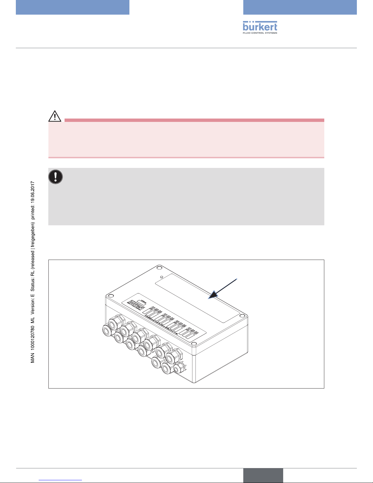
5.1.3 Identification
Profibus PA Interface: Digital I/O
Type label
Fig. 1: Location of the type label
english
Type 8643 PA
Page 12
12
System Description
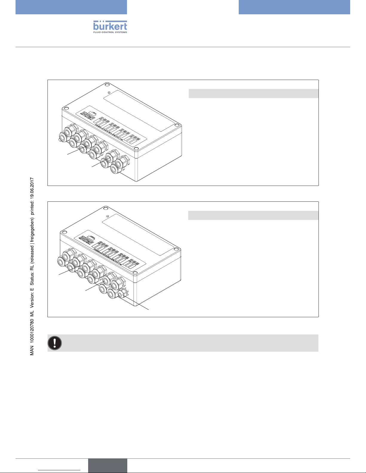
5.1.4 Cable connections on the body
1
2
Profibus PA Interface: Digital I/O
No. Designation
1
Cable glands for intrinsically safe circuits
(8 screw joints, blue)
2
Cable glands for bus and power supply
(4 screw joints, black)
Fig. 2: Location of the cable connections on the aluminium body of the device
1
2
3
Profibus PA Interface: Digital I/O
No. Designation
1
Cable glands for intrinsically safe circuits
(8 screw joints, blue)
2
Cable glands for bus and power supply
(4 screw joints, black)
3
Cable gland for earth cable PA
(potential equalisation)
Fig. 3: Location of the cable connections on the plastic body of the device
When delivered, the cable glands are covered with protective caps. These protective caps must remain
on the cable glands until the cables are connected to keep out dirt.
english
Type 8643 PA
Page 13
13
System Description
5.1.5 LED display
LED 1 green
LED 2
green
Fig. 4: Location of the LED display
LED 1 is lit when voltage is applied to the bus supply.
LED 2 is lit if the device is using cyclic data transfer.
LED 3 is lit if the device is not using cyclic data transfer
(only after Power on or if the Watchdog is active).
If neither LED 2 nor LED 3 is lit, check power supply!
5.2 Technical Data
Designation Values
Body material Polyester, aluminium
Colour black
Ambient temperature -20 ... +60 °C
Cable entry Polyamide cable glands
Protection class IP 65 (DIN EN 60529)
Protection class 3 (DIN EN 61140 (vDE 0140-1))
Ignition protection identification (complete device) ATEX:
II 2 (1) G Ex e mb [ia IIC Ga] IIC T4 Gb
II 2 (1) D Ex tb [ia IIIC Da] IIIC T65 °C Db IP65
IECEx:
Ex e mb [ia IIC Ga] IIC T4 Gb
Ex tb [ia IIIC Da] IIIC T65 °C Db IP65
Power supply voltage 4-wire version
Auxiliary supply 24 V
17 ... 32 V DC
english
Type 8643 PA
Page 14

14
System Description
Designation Values
Max. power requirement
Bus voltage
Power consumption of bus
200 mA (17 V)
140 mA (24 V)
110 mA (32 V)
9 ... 32 V DC
12 mA /17 mA FDE
Inputs
8, intrinsically safe, NAMUR
(in accordance with EN 60947-5-6)
Outputs
Outputs for pilot valves
min. switching current
min. holding current
Internal resistance
Off-load voltage
4, intrinsically safe
30 mA
1)
15 mA
330 ohm
24 V
1)
Power reduction to holding current after minimum 50 ms.
Designation Values
Electrical connections for inputs and outputs Screw terminals (up to 2.5 mm²)
Field bus interface
Ignition protection type
Electrical connection
Communication in accordance with IEC 1158-2
in accordance with FISCO
EEx i
4 screw terminals bus (up to 2.5 mm²)
3 screw terminals shield
(1x directly and 2x capacitively earthed)
Auxiliary supply
Ignition protection type
Electrical connection
Increased safety EEX e
4 screw terminals (up to 2.5 mm²)
Device key (see type label)
polyester body
aluminium body
8643-4-PO-XX-X-XXX
8643-4-AL-XX-X-XXX
• The cable resistance to the sensors and actuators may be max. 20 Ω.
• The Power I/O Box Type 8643 may be supplied with low safety voltage in accordance with VDE 0631 only.
• The Power I/O Box Type 8643 satisfies the conditions of the EMC Law. EN61000-6-2 Interference
Resistance, EN61000-6-4 Interference Emission
• The safety-related maximum values for operation in explosion-risk area can be found in the Type
Examination Certificate in the Appendix.
english
Type 8643 PA
Page 15
15
System Description
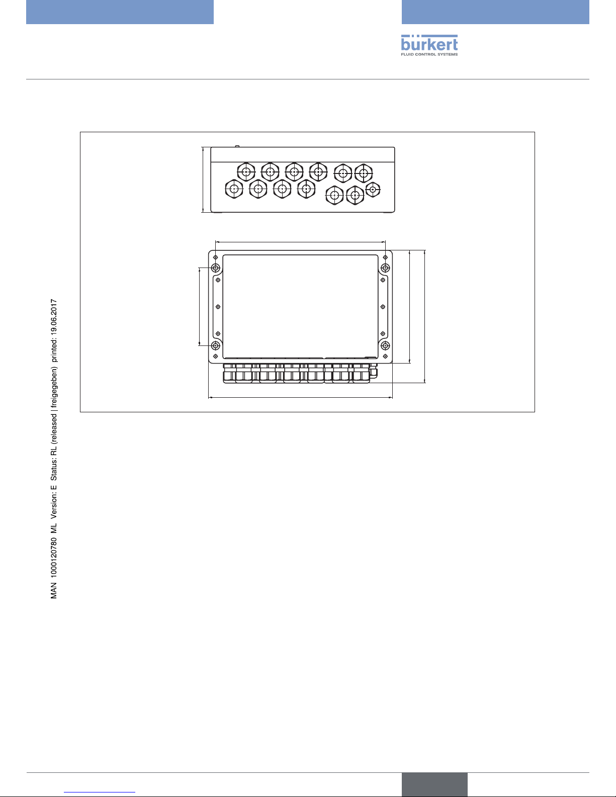
5.3 Dimensions
260
160
188
110
240
92
Fig. 5: Dimensions Type 8643
english
Type 8643 PA
Page 16

16
Installation
6 INSTALLATION
6.1 Safety instructions
DANGER!
Hazardous if used in explosion-risk area
Risk of explosion from electrical voltage!
The Power I/O Box Type 8643 is designed as ignition protection type Ex-e (increased safety).
▶ Before working on non-intrinsically safe circuits of the Power I/O Box Type 8643, always switch off the
operating voltage of the system!
Danger of explosion due to internal charging of the Power I/O Box Type 8643!
When the power supply to the Power I/O Box Type 8643 is switched off, the internally stored charge will not
be completely dissipated for 4 minutes. To prevent an explosion, switch off the power supply before connecting
or disconnecting Ex-e terminals.
▶ Do not remove the cover from the connection terminals for Ex-e switching circuits until the connected Ex-e
circuits have been disconnected from the power supply for longer than 4 minutes.
Danger of explosion if the allowable ambient temperature ranges are exceeded!
▶ Observe the respective ambient temperature range which is based on the type designation
(e.g. 8643-4-AL-KS-F-I/O), according to the table in the EC-Type Examination Certificate.
Danger of explosion due to unauthorized combination of the ignition protection types!
Due to unauthorized combination of the ignition protection types, the device is not suitable for use in the
explosion-protected area. If the device is nevertheless used in this area, there is a danger of explosion!
▶ If the bus supply of the device was operated once in ignition protection type of increased safety (e), the bus
supply may no longer be intrinsically safe in the ignition protection type (i).
WARNING!
Risk of injury from improper installation!
▶ Installation may be carried out by authorized technicians only and with the appropriate tools!
▶ Observe the national regulations which apply to the installation/operation of electrical equipment in areas
where there is a risk of explosions!
Risk of injury from unintentional activation of the system and an uncontrolled restart!
▶ Secure system from unintentional activation.
▶ Following assembly, ensure a controlled restart.
english
Type 8643 PA
Page 17

17
Installation
NOTE!
Electrostatic sensitive components / modules.
The Power I/O Box Type 8643 contains electronic components which respond sensitively to electrostatic discharge (ESD).
Contact with electrostatically charged persons or objects is hazardous to these components. In the worst case
scenario, they will be destroyed immediately or will fail after start-up.
• Observe the requirements in accordance with EN 100 015 – 1 to minimize or avoid the possibility of damage
caused by sudden electrostatic discharge!
• Do not touch the electronic components while the power supply voltage is on!
Function restriction
The function of the device may be restricted without potential equalisation.
• Connect the earth terminal point on the body to the potential equalisation (PA).
6.2 Installation instructions
NOTE!
• The allowable technical data must not be exceeded.
• Preferred installation position:
Cable glands face downwards!
• The cable glands on the body have a metric thread.
• Use only shielded lines to supply the bus!
• Place the bus line shields on the designated screw terminals as short as possible!
• When the work is complete, carefully close the body again!
This device complies with the EMC Directive of the Council of the European Union No. 2004/108/EG.
Follow the installation instructions to satisfy the conditions of this directive.
english
Type 8643 PA
Page 18

18
Installation
6.3 Cable glands
WARNING!
Danger of explosion!
No explosion protection if cable glands are defective or wrong.
▶ Replace defective cable glands only with Ex-authorized (EEx e II) cable glands with adequate application
temperature range (see Type Examination Certificate).
• At the factory all cable glands are sealed with a plug (protection class IP65).
• Seal all unused cable glands with a plug to maintain IP protection (IP65).
M16 x 1.5 potential equalisation PA
(with plastic body)
4 black M20 x 1.5 cable glands bus and power supply
8 blue M20 x 1.5 cable glands for intrinsically safe circuits
(sensor/actuator outputs)
Fig. 6: Cable glands
The body features eight blue cable glands for the intrinsically safe circuits and four black glands for the bus and
power supply with increased safety.
The bus and power supplies each have two M20x1.5 glands to loop through the supply lines.
For sensors and actuators each output (with two sensors) has an M20x1.5 cable gland.
Devices with plastic body have an M16x1.5 cable gland for the internal earth connection (PA).
Devices with metal body (e.g. aluminium) have an earth connection on the outside of the body.
english
Type 8643 PA
Page 19

19
Installation
6.4 Electrical Connections
6.4.1 Safety instructions
NOTE!
No function if reverse polarity.
▶ Pay attention to the polarity of the terminals!
The device is protected against polarity reversal.
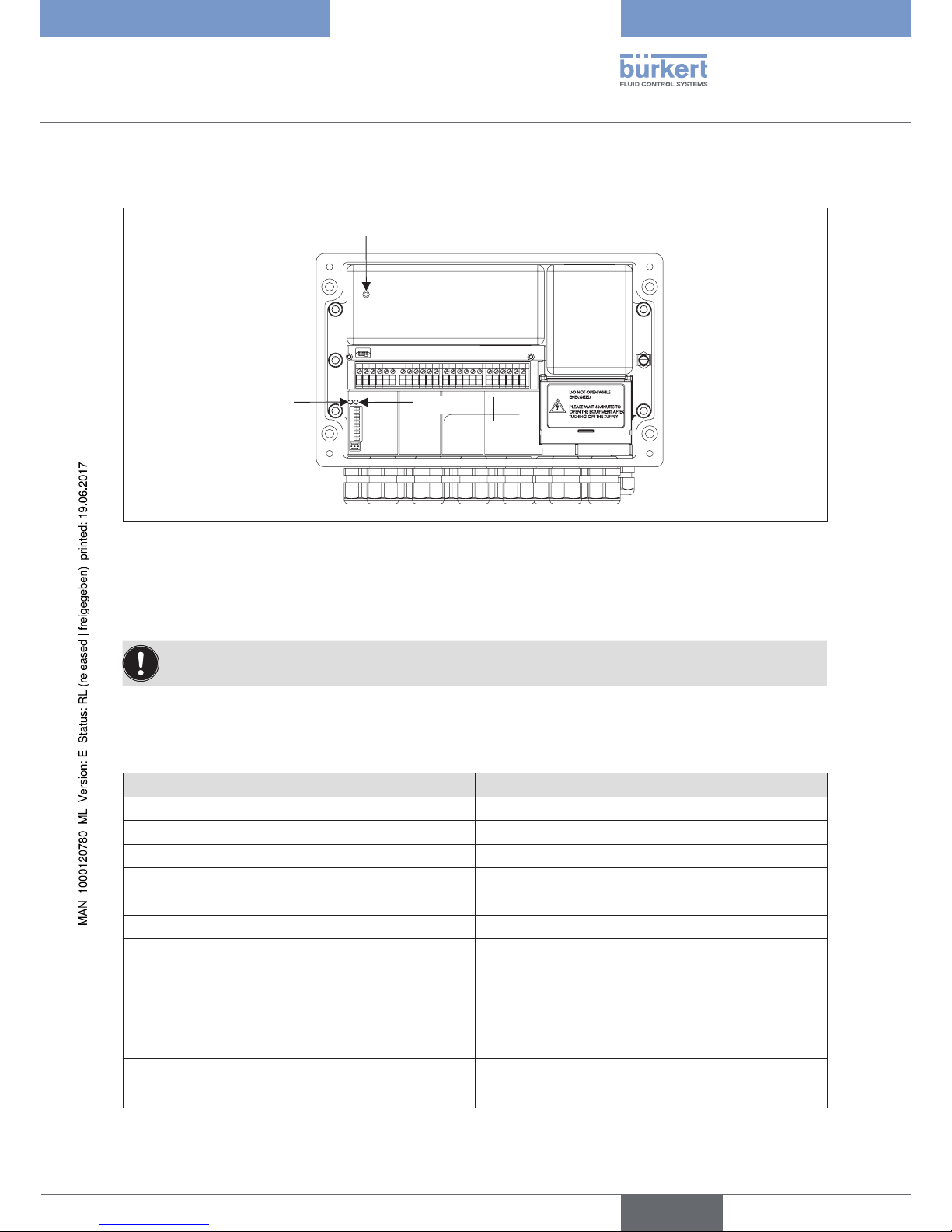
6.4.2 Overview of the terminals and outputs
LED module
Address
BUS
Power supply 24 V DC
Bus
Shield
Actuators and Sensors
Fig. 7: Overview of terminals and outputs
english
Type 8643 PA
Page 20

20
Installation
6.4.3 Supply connection
Terminal 24 V DC
Connection for the power supply in the ignition protection type EEx e II. Max. connected loads see EC Type
Examination Certificate.
Bus terminal
Connection for the bus supply in accordance with IEC 1158-2.
There are two options available depending on the device model.
DANGER!
Danger of explosion due to unauthorized combination of the ignition protection types!
Unauthorized combination of the ignition protection types may cause hazardous situations!
▶ If the bus supply of the device was operated once in ignition protection type of increased safety (e), the bus
supply may no longer be intrinsically safe in the ignition protection type (i).
Bus supply with increased safety
Ignition protection type: EEx e II
• Intrinsically safe bus supply
Ignition protection type EEx ia IIC or ignition protection type EEx ia IIB
english
Type 8643 PA
Page 21

21
Installation
6.4.4 Connection of the SHIELD terminal
Connection for the cable shield of the bus line.
There are two options available for connection of the cable shield.
8. Direct earthing to the body (PA)
Connection of the cable shield:
→ Connect cable shield to the right terminal.
9. Capacitive earthing to the body (PA)
To discharge EMC interference to the earth potential, a capacitor with a capacity <10 nF is installed in the device.
If several devices are connected in parallel with capacitive shield earthing, the energy stored in the capacitors in
the event of a fault must not exceed the authorized limit values (see IEC/EN 60079-11) of the valid gas group. To
determine the stored energy, the maximum authorized bus voltage must be taken into consideration.
Connection of the cable shield:
→ Connect cable shield to the left 2 terminals.
→ Connect the shield in a continuous manner.
→ Earth the shield at a point in the bus line.
The terminals for the bus and power supply have a cover to protect against unintentional contact.
Body terminals
Connection for the potential equalisation (PA).
Electromagnetic compatibility
To ensure an adequate discharge of EMC interference, connect the earth terminal to the potential equalisation
(PA) via a shortest possible line. If this is not possible, use suitable measures to prevent electromagnetic interference from unduly influencing the Power I/O Box Type 8643.
Connecting cable:
• minimum cross-section: 2.5 mm²
• maximum length: 0.5 m
To ensure that the body is not leaking, the outer diameter of the connecting cable must be min. 4 mm for
the plastic body.
english
Type 8643 PA
Page 22

22
Installation
6.4.5 Actuator terminals
The Power I/O Box Type 8643 has power-reduced outputs. This means that the current required to activate
the actuator is provided at the switching moment and reduced to the holding current after a specified time.
The actuator outputs are designed as ignition protection type ia.
Terminal designation
Polarity + -
Output 1 1 2
Output 2 7 8
Output 3 13 14
Output 4 19 20
6.4.6 Sensor terminals
The Power I/O Box Type 8643 has eight NAMUR sensor inputs; two sensors are always assigned to one actuator
output.
The sensors signal back the end positions of a connected process valve. However, they can also signal back
other process values independently of the actuator outputs (e.g. operator buttons, scraper end positions..).
The sensor inputs are designed as ignition protection type ia.
Output Sensor Terminal designation
Polarity + Polarity -
1
1.1 3 4
1.2 5 6
2
2.1 9 10
2.2 11 12
3
3.1 15 16
3.2 17 18
4
4.1 21 22
4.2 23 24
english
Type 8643 PA
Page 23

23
Setting the station addresses
7 SETTING THE STATION ADDRESSES
DIP switches 1 to 7 Bit 1 to Bit 7
The DIP switches are not read in until the device is switched on.
In the case of the PROFIBUS PA each station receives an address. These addresses are set with the DIP
switches 1 to 7.
The permitted address area is between 3 and 124.
Settings:
2
0
2
1
2
2
2
3
2
4
2
5
2
6
DIP -1 DIP -2 DIP -3 DIP -4 DIP -5 DIP -6 DIP -7 Address
ON
OFF
ON
OFF
ON
OFF
OFF
ON
OFF
ON
ON
ON
OFF
ON
ON
ON
OFF
ON
ON
ON
OFF
ON
ON
ON
OFF
ON
ON
ON
3
:
:
124
125
126
* Delivery status: Address 126
If switch 8 is in the ON position, the internal address is used! This address can be set via the field bus.
7.1 LED display
The LED flashes if the device is using cyclic data transfer.
The LED lights up briefly when the device is connected.
If the device establishes an internal fault, the LED stays on constantly.
7.2 Watchdog
To improve fault detection, we recommend operating the device using cyclic data transfer with “DP watchdog”.
perm. address
range 3 ... 124
english
Type 8643 PA
Page 24

24
Configuring the network
8 CONFIGURING THE NETWORK
8.1 Storage allocation for user data transfer
Basis: Handbook for your PLC
→ To implement the correct settings of the configuration program, copy the device-specific file (buer6521.GSD)
from Bürkert into the directory which contains the configuration software. To read in and process the configuration, please read the documentation for your PLC or your control system.
Further information on the storage allocation can be found in the handbook.
8.2 System parameters
All profile data refers to the profile version 3.0 class B.
This is where you will also find detailed documentation on the parameters.
• When writing parameters, ensure that the power is on!
8.2.1 Physical block
8.2.1.1. Slot 0
Parameter type:
N
Non-volatile parameter which must be observed in the operating cycle.
However, it does not belong to the static updating code.
S
Static, non-volatile; the version counter ST_REV is increased during the write
process.
D (dynamic)
The value is calculated in the block or read from another block.
C (constant)
The parameter does not change.
english
Type 8643 PA
Page 25

25
Configuring the network
Abs. index Length
(byte)
Type Description
17
2 N ST_REV
18
32 S TAG_DESC
19
2 S STRATEGY
20
1 S ALERT_KEY
21
1 S TARGET_MODE
22
3 N/S
(RCAS)
MODE_BLK
23
8 D ALARM_SUM (not yet in the profile)
24
16 C SOFTWARE_REVISION
25
16 C HARDWARE_REVISION
26
2 C DEVICE_MAN_ID
27
2 C DEVICE_ID
28
16 N Serial number
29
4 D DIANOSIS
30
6 D DIANOSIS_EXTENSION
31
4 C DIANOSIS_MASK
32
6 C DIANOSIS_MASK_EXTENSION
35
2 S FACTORY_RESET
36
32 S DESCRIPTOR
37
32 S DEVICE_MESSAGE
38
16 S DEVICE_INSTAL_DATE
39
1 S LOCAL_OP_ENA
40
1 S IDENT_NUMBER
69
17 D VIEW_1
Table 1: Physical block Slotindex 0
english
Type 8643 PA
Page 26

26
Configuring the network
8.2.1.2. Description of the standard parameters
These parameters are included in the physical block, in the function block and in the transducer block.
Parameter Description
ALARM_SUM
This parameter includes the current status of the block alarm. The parameter
ALARM_SUM is not yet supported.
ALERT_KEY
This parameter includes the identification number of the plant unit. As a result, the
location (plant unit) of an event can be detected.
MODE_BLK
This parameter includes the current mode and the permitted and normal mode of the
block.
ST_REV
A module has static parameters which are not changed by the process. Values are
assigned to these parameters during the configuration or optimisation. The values
of the parameters ST_REV must increase by 1 whenever a static block parameter is
changed. As a result, the parameter revision can be checked.
STRATEGY
Arrangement of the function module. The STRATEGY field can be used to group
blocks.
TAG_DESC
Each block can be assigned a written TAG description. TAG_DESC is the address
of the block. TAG_DESC must be unique and standard in the field bus system.
TARGET_MODE
The TARGET_MODUS includes the required mode which is usually specified by a
control application or by operating personnel.
8.2.1.3. Properties of the standard parameters
Rel. Index Variable Data type Storage Size Access
1
ST-REV Unsigned 16 N 2 r,w
2
TAG_DESC Octet String * S 32 r,w
3
STRATEGY Unsigned 16 S 2 r,w
4
ALERT_KEY Unsigned 8 S 1 r,w
5
TARGET_MODE Unsigned 8 S 1 r,w
6
MODUS_BLK
current
permitted
normal
DS-37
N**
Cst
Cst
3 r
7
ALARM_SUM DS-42 8 r
Table 2: Assignments of the standard parameters
* The preferred data type should be Visible String
** N-accepted mode = RCAS
english
Type 8643 PA
Page 27

27
Configuring the network
Abbreviations:
Storage (requested storage class)
N
Non-volatile parameter which must be observed in the operating cycle. However, it does
not belong to the static updating code.
S
Static, non-volatile; the version counter ST_REV is increased during the write process.
D (dynamic)
The value is calculated in the block or read from another block.
Cst (constant)
The parameter does not change.
Access
r
read access
w
write access
The standard parameter View Object
Rel. Index Variable View_1 View_2 View_3 View_4
1
ST-REV 2
2
TAG_DESCRIPTION
3
STRATEGY
4
ALERT_KEY
5
TARGET_MODUS
6
MODUS_BLK 3
7
ALARM_SUM 8
Table 3: View Object of the standard parameters
Mode structure
This data structure consists of character strings for current, set and normal modes.
Data type: Mode
Key attributes: Index = 37
Indicator: Number of the elements
Indicator: List of the elements
E Name of the element Data type (index) Size (byte)
1
current Unsigned 8 - (5) 1
2
permitted Unsigned 8 - (5) 1
3
normal Unsigned 8 - (5) 1
Table 4: List of the elements of the mode structure
english
Type 8643 PA
Page 28

28
Configuring the network
Out of service (O/S)
The block was not specified. If the initial value was specified during a certain failsafe value, the last value or the configured fail-safe value is retained.
Manual l (Man)
The output block is specified directly by the user by means of an interface
command.
Automatic (Auto)
The Invert parameter is used to form the output value.
Remote Cascade
(RCas)
The set-point block was set by a control application which works on an interface
device via the remote cascade parameter RCAS_IN.
The version of a function block or transducer block is checked by the mode parameter. Values of the subindex
mode are defined as follows:
1. Target
This is the mode which is requested by the user. The values which are authorized by parameters of the permitted
mode, are limited for target. The modes are specified by the bit string in the following manner:
Bit Mode
7
Out of service (O/S) - MSB
4
Manual (Man)
3
Automatic (Auto)
1
Remote - Cascade (RCas)
The “automatic” modes which are used in this profile are Auto and RCas; manual mode: Man. In the O/S mode
the normal algorithm is not implemented and each pending alarm is deleted.
2. Current
This is the present mode of the module which may differ from the target mode which is based on operating
conditions.
Alarm sum structure
This data structure consists of data which combines the 16 alarms.
Data type Alarm sum
Key attributes Index = 42
Attributes Number of elements =4
Attributes List of elements (indicated below)
E Name of the element Data type (index) Size (byte)
1
current Octet String - (10) 2
2
not acknowledged Octet String - (10) 2
3
not signalled Octet String - (10) 2
4
switched off Octet String - (10) 2
Table 5: List of elements and the sum structure
english
Type 8643 PA
Page 29

29
Configuring the network
The bits of the bit string are assigned to the following alarms:
Bit
Alarm
0
Discrete alarm (LSB)
1
HI_HI_Alarm
2
HI_Alarm
3
LO_LO_Alarm
4
LO_Alarm
5
reserved
6
reserved
7
Block Alarm (e.g. increase of St_Rev)
8-15
reserved
8.2.1.4. Parameter description of the physical block
Parameter Parameter description
DEVICE_ID
Identification of the field device
DEVICE_MAN_ID
Identification code of the field device manufacturer (Bürkert = 120)
DEVICE_SER_NUM
Serial number of the manufacturer
DIANOSIS
Precise information on the device, coded bit by bit.
DIANOSIS_MASK
Definition of supported DIAGNOSIS information bits
0 = not supported
1 = supported
DIA_MEM_CHKSUM
Storage error
DIA_CONF_INVAL
Invalid configuration
DIA_WARMSTART
Warm start
DIA_COLDSTART
Cold start
HARDWARE_REVISION
Version number of the hardware for the field device
SOFTWARE_REVISION
Version number of the software for the field device
DIANOSIS_EXTENSION
Additional diagnosis for device manufacturer
DIANOSIS_MASK_
EXTENSION
Definition of supported information
FACTORY_RESET
1 Reset to standard values
2506 Warm start
2712 Reset the bus address, IDENT_NUMBER_SELECTOR is not reset
Parameter
Parameter description
DESCRIPTOR
User-definable text to describe the device within the application
english
Type 8643 PA
Page 30

30
Configuring the network
Parameter Parameter description
DEVICE_MESSAGE
User-definable message to describe the device within the application or system
LOCAL_OP_ENA
0 No local operation
DEVICE_INSTAL_DATE
Date the device was installed
IDENT_NUMBER
Selection of the GSD file
0 Specific to profile
1 Specific to manufacturer (standard value)
VIEW_1
includes the variables:
ST_REV
MODE_BLK
ALARM_SUM
DIANOSIS
Abbreviations:
Storage (requested storage class)
N
Non-volatile parameter which must be observed in the operating cycle.
However, it does not belong to the static updating code.
D (dynamic)
The value is calculated in the block or read from another block.
Cst (constant)
The parameter does not change.
S
Static, non-volatile; the version counter ST_REV is increased during the write process.
Access
r
read access
w
write access
Abs. index Variable Data type Storage Length Access
24
SOFTWARE_REVISION OctetString Cst 16 r
25
HARDWARE_REVISION OctetString Cst 16 r
26
DEVICE_MAN_ID OctetString Cst 2 r
27
DEVICE_ID OctetString Cst 2 r
28
Serial number OctetString Cst 16 r
29
DIANOSIS OctetString Byte =
4 MSB = 1 more
diagnosis available
D 4 r
30
DIANOSIS_EXTENSION OctetString D 6 r
31
DIANOSIS_MASK OctetString Cst 4 r
32
DIANOSIS_MASK_
EXTENSION
OctetString Cst 6 r
35
FACTORY_RESET Unsigned16 S 2 r/w
36
DESCRIPTOR OctetString S 32 r/w
37
DEVICE_MESSAGE OctetString S 32 r/w
38
DEVICE_INSTAL_DATE OctetString S 16 r/w
39
LOCAL_OP_ENA Unsigned8 N 1 r/w
english
Type 8643 PA
Page 31

31
Configuring the network
Abs. index Variable Data type Storage Length Access
40
IDENT_NUMBER Unsigned8 S 1 r/w
Table 6: Assignments of the standard parameters
All parameters of the physical block are acyclic!
Parameter structure of the bit string DIAGNOSIS
Bit Notation Description *
4
DIA_MEM_CHKSUM Storage checksum error R
10
DIA_CONF_INVAL Configuration not valid R
11
DIA_WARMSTART Repeated start request
(warm start request)
A
12
DIA_COLDSTART Restart request (cold start
request)
A
Table 7: Diagnosis of the parameter coding of the Physical Block
Coding of the diagnosis parameters
Values of the diagnosis bits:
0 = not set
1 = set
* = display class:
R = display is active for as long as the reason of the message is available.
A = display is automatically reset after the read process.
The standard parameter View Object
Rel. Index Variable View_1 View_2 View_3 View_4
1
ST_REV 2
2
TAG_DESCRIPTION
3
STRATEGY
4
ALERT_KEY
5
TARGET_MODUS
6
MODUS _BLK 3
7
ALARM_SUM 8
Table 8: View Object of the standard parameters
english
Type 8643 PA
Page 32

32
Configuring the network
Rel. Index Parameter notation Operation
Dynamic
VIEW_1
Operation
Static VIEW_2
All Dynamic
VIEW_3
Other Static
VIEW_4
8
SOFTWARE_REVISION
9
HARDWARE_REVISION
10
DEVICE_MAN_ID
11
DEVICE_ID
12
DEVICE_SER_NUM
13
DIANOSIS 4
14
DIANOSIS_EXTENSION
15
DIANOSIS_MASK
16
DIANOSIS_MASK_
EXTENSION
Table 9: Display objects of the physical block
8.2.2 Transducer Block
Abbreviations:
Storage
N
Non-volatile parameter which must be observed in the operating cycle. However, it does
not belong to the static updating code.
S
Static, non-volatile; the version counter ST_REV is increased during the write process.
D (dynamic)
The value is calculated in the block or read from another block.
Access
r
read access
w
write access
Transfer type
a
acyclic
cyc
cyclic
english
Type 8643 PA
Page 33

33
Configuring the network
8.2.2.1. Slot 1 (valve 1)
Abs. index Variable Data type Storage Length Access
81
ST_REV Unsigned16 N 2 r/w
82
TAG_DESC OctedString S 32 r/w
83
STRATEGY Unsigned16 S 2 r/w
84
ALERT_KEY Unsigned8 S 1 r/w
85
TARGET_MODE Unsigned8 S 1 r/w
86
MODE_BLK DS-37 N/S (RCAS) 3 r
87
ALARM_SUM (not yet in the profile) DS-42 D 8 r
88
VALVE_MAN OctedString S 16 r/w
89
ACTUATOR_MAN OctedString S 16 r/w
90
VALVE_SER_NUM OctedString S 16 r/w
91
ACTUATOR_SER_NUM OctedString S 16 r/w
92
VALVE_ID OctedString S 16 r/w
93
ACTUATOR_ID OctedString S 16 r/w
94
ACTUATOR_ACTION Unsigned8 S 1 r/w
95 TRAVEL_COUNT Unsigned16 N 2 r/w
96
TRAVEL_COUNT_LIM Unsigned16 N 2 r/w
105
TRAVEL_TIME_CLOSE_OPEN Unsigned16 N 2 r/w
106
TRAVEL_TIME_OPEN_CLOSE Unsigned16 N 2 r/w
109
TRAVEL_TIME_CLOSE_OPEN_TOL Unsigned16 S 2 r/w
110
TRAVEL_TIME_OPEN_CLOSE_TOL Unsigned16 S 2 r/w
111
SELF_CALIB_CMD Unsigned8 N 1 r/w
112
SELF_CALIB_STATUS Unsigned8 N 1 r
113
SENSOR_WIRE_CHECK Unsigned8 S 1 r/w
124
VIEW 13
Table 10: Parameter of the Transducer Block Slot 1
english
Type 8643 PA
Page 34

34
Configuring the network
8.2.2.2. Slot 2 (valve 2)
Abs. index Variable Data type Storage Length Access
81
ST_REV Unsigned16 N 2 r/w
82
TAG_DESC OctedString S 32 r/w
83
STRATEGY Unsigned16 S 2 r/w
84
ALERT_KEY Unsigned8 S 1 r/w
85
TARGET_MODE Unsigned8 S 1 r/w
86
MODE_BLK DS-37 N/S (RCAS) 3 r
87
ALARM_SUM (not yet in the profile) DS-42 D 8 r
88
VALVE_MAN OctedString S 16 r/w
89
ACTUATOR_MAN OctedString S 16 r/w
90
VALVE_SER_NUM OctedString S 16 r/w
91
ACTUATOR_SER_NUM OctedString S 16 r/w
92
VALVE_ID OctedString S 16 r/w
93
ACTUATOR_ID OctedString S 16 r/w
94
ACTUATOR_ACTION Unsigned8 S 1 r/w
95
TRAVEL_COUNT Unsigned16 N 2 r/w
96
TRAVEL_COUNT_LIM Unsigned16 N 2 r/w
105
TRAVEL_TIME_CLOSE_OPEN Unsigned16 N 2 r/w
106
TRAVEL_TIME_OPEN_CLOSE Unsigned16 N 2 r/w
109
TRAVEL_TIME_CLOSE_OPEN_TOL Unsigned16 S 2 r/w
110
TRAVEL_TIME_OPEN_CLOSE_TOL Unsigned16 S 2 r/w
111
SELF_CALIB_CMD Unsigned8 N 1 r/w
112
SELF_CALIB_STATUS Unsigned8 N 1 r
113
SENSOR_WIRE_CHECK Unsigned8 S 1 r/w
124
VIEW 13
Table 11: Parameter of the Transducer Block Slot 2
english
Type 8643 PA
Page 35

35
Configuring the network
8.2.2.3. Slot 3 (valve 3)
Abs. index Variable Data type Storage Length Access
81
ST_REV Unsigned16 N 2 r/w
82
TAG_DESC OctedString S 32 r/w
83
STRATEGY Unsigned16 S 2 r/w
84
ALERT_KEY Unsigned8 S 1 r/w
85
TARGET_MODE Unsigned8 S 1 r/w
86
MODE_BLK DS-37 N/S (RCAS) 3 r
87
ALARM_SUM (not yet in the profile) DS-42 D 8 r
88
VALVE_MAN OctedString S 16 r/w
89
ACTUATOR_MAN OctedString S 16 r/w
90
VALVE_SER_NUM OctedString S 16 r/w
91
ACTUATOR_SER_NUM OctedString S 16 r/w
92
VALVE_ID OctedString S 16 r/w
93
ACTUATOR_ID OctedString S 16 r/w
94
ACTUATOR_ACTION Unsigned8 S 1 r/w
95
TRAVEL_COUNT Unsigned16 N 2 r/w
96
TRAVEL_COUNT_LIM Unsigned16 N 2 r/w
105
TRAVEL_TIME_CLOSE_OPEN Unsigned16 N 2 r/w
106
TRAVEL_TIME_OPEN_CLOSE Unsigned16 N 2 r/w
109
TRAVEL_TIME_CLOSE_OPEN_TOL Unsigned16 S 2 r/w
110
TRAVEL_TIME_OPEN_CLOSE_TOL Unsigned16 S 2 r/w
111
SELF_CALIB_CMD Unsigned8 N 1 r/w
112
SELF_CALIB_STATUS Unsigned8 N 1 r
113
SENSOR_WIRE_CHECK Unsigned8 S 1 r/w
124
VIEW 13
Table 12: Parameter of the Transducer Block Slot 3
english
Type 8643 PA
Page 36

36
Configuring the network
8.2.2.4. Slot 4 (valve 4)
Abs. index Variable Data type Storage Length Access
81
ST_REV Unsigned16 N 2 r/w
82
TAG_DESC OctedString S 32 r/w
83
STRATEGY Unsigned16 S 2 r/w
84
ALERT_KEY Unsigned8 S 1 r/w
85
TARGET_MODE Unsigned8 S 1 r/w
86
MODE_BLK DS-37 N/S (RCAS) 3 r
87
ALARM_SUM (not yet in the profile) DS-42 D 8 r
88
VALVE_MAN OctedString S 16 r/w
89
ACTUATOR_MAN OctedString S 16 r/w
90
VALVE_SER_NUM OctedString S 16 r/w
91
ACTUATOR_SER_NUM OctedString S 16 r/w
92
VALVE_ID OctedString S 16 r/w
93
ACTUATOR_ID OctedString S 16 r/w
94
ACTUATOR_ACTION Unsigned8 S 1 r/w
95
TRAVEL_COUNT Unsigned16 N 2 r/w
96
TRAVEL_COUNT_LIM Unsigned16 N 2 r/w
105
TRAVEL_TIME_CLOSE_OPEN Unsigned16 N 2 r/w
106
TRAVEL_TIME_OPEN_CLOSE Unsigned16 N 2 r/w
109
TRAVEL_TIME_CLOSE_OPEN_TOL Unsigned16 S 2 r/w
110
TRAVEL_TIME_OPEN_CLOSE_TOL Unsigned16 S 2 r/w
111
SELF_CALIB_CMD Unsigned8 N 1 r/w
112
SELF_CALIB_STATUS Unsigned8 N 1 r
113
SENSOR_WIRE_CHECK Unsigned8 S 1 r/w
124
VIEW 13
Table 13: Parameter of the Transducer Block Slot 4
english
Type 8643 PA
Page 37

37
Configuring the network
8.2.2.5. Description of the block parameters of the transducer
• Suitable for solenoid valve application;
• Two proximity switches for each solenoid outlet;
• The input signals indicate the ON/OFF status of the valve.
Parameter Description
VALVE_MAN
Name of the valve manufacturer
ACTUATOR_MAN
Name of the actuator manufacturer
VALVE_SER_NUM
Serial number of the valve belonging to the device
ACTUATOR_SER_NUM
Serial number of the actuator belonging to the device
VALVE_ID
Identification of the valve (valve type)
ACTUATOR_ID
Identification of the actuator (actuator type)
ACTUATOR_ACTION
Safety position if actuator or valve has power failure:
0 not initialized
1 open
2 closed
TRAVEL_COUNT
Number of cycles from “open” to “closed” and from “closed” to “open”. The number
range of the TRAVEL_COUNT exceeds the storage capability of the EEPROM
TRAVEL_COUNT_LIM
Limit of the parameter TRAVEL_COUNT; if 0, TRAVEL_COUNT_LIM is not processed. If the LIMIT values are exceeded, the corresponding bit in the parameter
CHECK_BACK is set.
TRAVEL_TIME_CLOSE_
OPEN
Set-point value for the time in seconds between the change of status from CLOSED
to OPEN; if 0, the time is not processed. If the time is exceeded, the corresponding
bit in the parameter CHECK_BACK is set. Times less than 0.5 seconds cannot be
monitored.
TRAVEL_TIME_OPEN_
CLOSE
Set-point value for the time in seconds between the change of status from OPEN to
CLOSED; if 0, the time is not processed. If the time is exceeded, the corresponding
bit in the parameter CHECK_BACK is set. Times less than 0.5 seconds cannot be
monitored.
TRAVEL_TIME_CLOSE_
OPEN_TOL
Maximum time difference between TRAVEL_TIME_CLOSE_OPEN and the current
switching time
TRAVEL_TIME_OPEN_
CLOSE_TOL
Maximum time difference between TRAVEL_TIME_OPEN_CLOSE and the current
switching time
SELF_CALIB_CMD
Device-specific calibration
- - - - - - x y
y = 0 de-energized active
y = 1 energized active
x = 0 Sensor 1 displays “Valve open”
x = 1 Sensor 1 displays “Valve closed”
SELF_CALIB_STATUS
Result or status of the device-specific calibration (depending on manufacturer)
0 Standard setting
english
Type 8643 PA
Page 38

38
Configuring the network
Parameter Description
SENSOR_WIRE_CHECK
Activation of the line break or short-circuit detection
List of permissible values:
0 Line break or short-circuit detection activated
1 Line break detection activated Short-circuit detection not activated
2 Line break detection not activated Short-circuit detection activated
3 Line break or short-circuit detection not activated
The standard parameter View Object
Rel. Index Variable View_1 View_2 View_3 View_4
1
ST-REV 2
2
TAG_DESCRIPTION
3
STRATEGY
4
ALERT_KEY
5
TARGET_MODUS
6
MODUS_BLK 3
7
ALARM_SUM 8
Table 14: View Object of the standard parameters
english
Type 8643 PA
Page 39

39
Configuring the network
8.2.3 Function block
8.2.3.1. Slot 1 (valve 1)
Abs. index Variable Data type Storage Length Access Transfer
type
17
ST_REV Unsigned16 N 2 r/w a
18
TAG_DESC OctedString S 32 r/w a
19
STRATEGY Unsigned16 S 2 r/w a
20
ALERT_KEY Unsigned8 S 1 r/w a
21
TARGET_MODE Unsigned8 S 1 r/w a
22
MODE_BLK DS-37 N/S (RCAS) 3 r a
23
ALARM_SUM
(not yet in the profile)
DS-42 D 8 r a
24
Batch DS-67 D 10 r/w a
25
SP_D cyclic value bit 0
(LSB) valve position
DS-34 D 2 r/w a/cyc
26
OUT_D value bit 0
(LSB) valve position
DS-34 D 2 r
28
READ_BACK_D
(cyclic possible)
DS-34 D 2 r a/cyc
30
RCAS_IN_D
(cyclic possible)
value bit 0 (LSB)
valve position
DS-34 D 2 r/w a/cyc
33
CHANNEL
(only one value possible)
Unsigned16 S 2 r/w a
34
INVERT Unsigned16 S 1 r/w a
35
FSAVE_TIME Float S 4 r/w a
36
FSAVE_TYPE Unsigned8 S 1 r/w a
37
FSAVE_VAL_D Unsigned8 S 1 r/w a
38
RCAS_OUT_D
(cyclic possible)
DS-34 D 2 r a,cyc
39
SIMULATE DS-51 S 3 r/w a
49
CHECK_BACK
(cyclic possible)
BitString D 3 r a,cyc
50
CHECK_BACK_MASK BitString N 3 r a
79
VIEW_1
Table 15: Function block Slot 1
english
Type 8643 PA
Page 40

40
Configuring the network
8.2.3.2. Slot 2 (valve 2)
Abs. index Variable Data type Storage Length Access Transfer
type
17
ST_REV Unsigned16 N 2 r/w a
18
TAG_DESC OctedString S 32 r/w a
19
STRATEGY Unsigned16 S 2 r/w a
20
ALERT_KEY Unsigned8 S 1 r/w a
21
TARGET_MODE Unsigned8 S 1 r/w a
22
MODE_BLK DS-37 N/S (RCAS) 3 r a
23
ALARM_SUM
(not yet in the profile)
DS-42 D 8 r a
24
Batch DS-67 D 10 r/w a
25
SP_D cyclic value bit 0
(LSB) valve position
DS-34 D 2 r/w a/cyc
26
OUT_D value bit 0
(LSB) valve position
DS-34 D 2 r a
28
READ_BACK_D
(cyclic possible)
DS-34 D 2 r a/cyc
30
RCAS_IN_D
(cyclic possible)
value bit 0 (LSB)
valve position
DS-34 D 2 r/w a/cyc
33
CHANNEL
(only one value possible)
Unsigned16 S 2 r/w a
34
INVERT Unsigned16 S 1 r/w a
35
FSAVE_TIME Float S 4 r/w a
36
FSAVE_TYPE Unsigned8 S 1 r/w a
37
FSAVE_VAL_D Unsigned8 S 1 r/w a
38
RCAS_OUT_D
(cyclic possible)
DS-34 D 2 r a,cyc
39
SIMULATE DS-51 S 3 r/w a
49
CHECK_BACK
(cyclic possible)
BitString D 3 r a,cyc
50
CHECK_BACK_MASK BitString N 3 r a
79
VIEW_1
Table 16: Function block Slot 2
english
Type 8643 PA
Page 41

41
Configuring the network
8.2.3.3. Slot 3 (valve 3)
Abs. index Variable Data type Storage Length Access Transfer
type
17
ST_REV Unsigned16 N 2 r/w a
18
TAG_DESC OctedString S 32 r/w a
19
STRATEGY Unsigned16 S 2 r/w a
20
ALERT_KEY Unsigned8 S 1 r/w a
21
TARGET_MODE Unsigned8 S 1 r/w a
22
MODE_BLK DS-37 N/S (RCAS) 3 r a
23
ALARM_SUM
(not yet in the profile)
DS-42 D 8 r a
24
Batch DS-67 D 10 r/w a
25
SP_D cyclic value bit 0
(LSB) valve position
DS-34 D 2 r/w a/cyc
26
OUT_D value bit 0
(LSB) valve position
DS-34 D 2 r a
28
READ_BACK_D
(cyclic possible)
DS-34 D 2 r a/cyc
30
RCAS_IN_D
(cyclic possible)
value bit 0 (LSB)
valve position
DS-34 D 2 r/w a/cyc
33
CHANNEL
(only one value possible)
Unsigned16 S 2 r/w a
34
INVERT Unsigned16 S 1 r/w a
35
FSAVE_TIME Float S 4 r/w a
36
FSAVE_TYPE Unsigned8 S 1 r/w a
37
FSAVE_VAL_D Unsigned8 S 1 r/w a
38
RCAS_OUT_D
(cyclic possible)
DS-34 D 2 r a,cyc
39
SIMULATE DS-51 S 3 r/w a
49
CHECK_BACK
(cyclic possible)
BitString D 3 r a,cyc
50
CHECK_BACK_MASK BitString N 3 r a
79
VIEW_1
Table 17: Function block Slot 3
english
Type 8643 PA
Page 42

42
Configuring the network
8.2.3.4. Slot 4 (valve 4)
Abs. index Variable Data type Storage Length Access Transfer
type
17
ST_REV Unsigned16 N 2 r/w a
18
TAG_DESC OctedString S 32 r/w a
19
STRATEGY Unsigned16 S 2 r/w a
20
ALERT_KEY Unsigned8 S 1 r/w a
21
TARGET_MODE Unsigned8 S 1 r/w a
22
MODE_BLK DS-37 N/S (RCAS) 3 r a
23
ALARM_SUM
(not yet in the profile)
DS-42 D 8 r a
24
Batch DS-67 D 10 r/w a
25
SP_D cyclic value bit 0
(LSB) valve position
DS-34 D 2 r/w a/cyc
26
OUT_D value bit 0
(LSB) valve position
DS-34 D 2 r a
28
READ_BACK_D
(cyclic possible)
DS-34 D 2 r a/cyc
30
RCAS_IN_D
(cyclic possible)
value bit 0 (LSB)
valve position
DS-34 D 2 r/w a/cyc
Table 18: Function block Slot 4
english
Type 8643 PA
Page 43

43
Configuring the network
8.2.3.5. Description of the block parameters of the function block
Parameter
Description
READBACK_D
This parameter returns the position of the valve and the sensors.
Bit 7 6 5 4 3 2 1 0
0 0 Do not initialize
0 1 Closed
1 0 Open
1 1 On the move
Status sensor 1
Short-circuit sensor
No-load sensor 1
Status sensor 2
Short-circuit sensor
No-load sensor 2
1 = active
0 = inactive
SP_D
Set-point value
Bit 0 in the value specifies the valve position. The transferred status must be a
“good” status, e.g. 0x80.
OUT_D
Process value of the valve position. Bit 0 in the value indicates the valve position.
RCAS_IN_D
Set-point value in the RCAS status (Remote Cascade). Bit 0 in the value specifies
the valve position. The transferred status must be a “good” status, e.g. 0x80.
RCAS_OUT_D
Process value of the valve position in the RCAS status. Bit 0 in the value indicates
the valve position.
CHANNEL
Indicates the transducer block. There are channels 1-4. The function blocks are permanently assigned.
INVERT
Inverts the set-point value in the AUTO or RCAS status0 = do not invert1 = invert
FSAVE_TIME
Time in seconds after which the “Failsave” action starts following a break in the
cyclic communication. The maximum value for this time is approx. 18 hours.
FSAVE_TYP
Response to “Fail save”
0 = Valve retains the last status
1 = Valve switches according to FSAVE_VAL_D
2 = Isolate valve
FSAVE-VAL-D
Valve position in “Fail save”, if selected.
SIMULATE
Allows the simulation of READBACK_D
english
Type 8643 PA
Page 44

44
Configuring the network
Parameter
Description
CHECK_BACK
Information on the device
Bit Information
0 in “Fail save” position
8 Valve opens
9 Valve closes
16 Number of switching cycles specified in TRAVEL_COUNT_LIM is
exceeded.
20 Time to close exceeded.
21 Time to open exceeded.
1 = active
0 = inactive
CHECK_BACK_MASK
Specification of the information supported in the CHECK_BACK
1 = supported
0 = not supported
8.2.3.6. Structure of the cyclic data
The selection options of the cyclic data in the GSD file are indicated below:
The device operates with the GSD for 8643 as well as with the GSD for 8642.
Module=“EMPTY” 0x00
EndModule
Module=“SP_D” 0xA1
EndModule
Module=“SP_D_READBACK_D” 0xC1, 0x81, 0x81, 0x83
EndModule
Module=“SP_D_CHECKBACK_D” 0xC1, 0x81, 0x82, 0x92
EndModule
Module=“SP_D_READBACK_D_CHECKBACK_D” 0xC1, 0x81, 0x84, 0x93
EndModule
Module=“RCAS_IN_D_RCAS_OUT_D” 0xC1, 0x81, 0x81, 0x8C
EndModule
Module=“RCAS_IN_D_RCAS_OUT_D_CHECKBACK” 0xC1, 0x81, 0x84, 0x9C
EndModule
Module=“SP_D_READBACK_D_RCAS_IN_D_RCAS_0” 0xC1, 0x83, 0x86, 0x9F
EndModule
The description of the data can be found in the previous chapter. The sequence corresponds to that of the
function block.
english
Type 8643 PA
Page 45

45
Malfunctions
9 MALFUNCTIONS
Malfunction Possible cause Remedial action
Valves do not switch: No or inadequate oper-
ating voltage.
→ Check the electrical connection.
→ Ensure the operating voltage according to type plate.
Inadequate or no
pressure supply.
→ Design the pressure supply with the largest possible
volume (even for upstream devices such as pressure
controllers, maintenance units, shut-off valves, etc.).
Minimum operating pressure ≥ 2.5 bar
Valves switch with a
delay or blow off at the
deaeration connections:
Inadequate or no
pressure supply.
→ Design the pressure supply with the largest possible
volume (even for upstream devices such as pressure
controllers, maintenance units, shut-off valves, etc.).
Minimum operating pressure ≥ 2.5 bar
Deaeration of the
exhaust air ducts inadequate due to too small
or dirty silencers (back
pressures).
→ Use appropriately sized silencers or expansion tanks.
→ Clean dirty silencers.
Impurities or foreign
objects in the pilot valve
or main valve.
→ Apply pulsed pressure to the exhaust air ducts to blow
out the impurities; install a new pilot valve or main
valve if this procedure is unsuccessful.
english
Type 8643 PA
Page 46

46
Packaging and Transport
10 PACKAGING AND TRANSPORT
NOTE!
Transport damages!
Inadequately protected equipment may be damaged during transport.
• During transportation protect the device against wet and dirt in shock-resistant packaging.
• Avoid exceeding or dropping below the allowable storage temperature.
• Protect the electrical interfaces of the coil and the pneumatic connections from damage by placing protective
caps on them.
11 STORAGE
NOTE!
Incorrect storage may damage the device.
• Store the device in a dry and dust-free location!
• Storage temperature. -20 … 60 °C.
12 DISPOSAL
→ Dispose of the device and packaging in an environmentally friendly manner.
NOTE!
Damage to the environment caused by device components contaminated with media.
• Observe applicable regulations on disposal and the environment.
Observe national waste disposal regulations.
english
Type 8643 PA
Page 47

Page 48

www.burkert.com
 Loading...