

Bürkert 8619, 8619 multiCELL WM AC, 8619 multiCELL WM DC, 8619 multiCELL Operating Instructions Manual
Operating Instructions
(from software version B.00.01)
Type 8619
8619 multiCELL WM AC
8619 multiCELL WM DC
8619 multiCELL
Modular transmitter/controller

We reserve the right to make technical changes without notice.
Technische Änderungen vorbehalten.
Sous réserve de modifications techniques.
© Bürkert SAS, 2017
Operating Instructions 1710/00_EU-ML 00569042 / Original_FR

Type 8619
English
1 ABOUT THE OPERATING INSTRUCTIONS ..........................................................................................................................8
1.1 Symbols used .........................................................................................................................................................................8
1.2 Definition of the word "device" ......................................................................................................................................8
1.3 Definition of the word "Industrial Ethernet" .............................................................................................................9
1.4 Validity of the Operating Instructions ........................................................................................................................9
2 INTENDED USE ...................................................................................................................................................................................9
3 BASIC SAFETY INFORMATION ...............................................................................................................................................10
4 GENERAL INFORMATION .............................................................................................................................................................11
4.1 Manufacturer's address and international contacts .........................................................................................11
4.2 Warranty conditions ..........................................................................................................................................................11
4.3 Information on the internet ..........................................................................................................................................11
5 DESCRIPTION ...................................................................................................................................................................................14
5.1 Area of application ............................................................................................................................................................14
5.2 Construction of a 8619 multiCELL ...........................................................................................................................14
5.3 Construction of a 8619 multiCELL WM DC ..........................................................................................................15
5.4 Construction of a 8619 multiCELL WM AC ..........................................................................................................16
5.5 Description of the LEDs for the connection to the network (Industrial Ethernet only) ...............17
5.6 Functional diagram ...........................................................................................................................................................18
5.7 Description of the rating plate ....................................................................................................................................22
6 TECHNICAL DATA ...........................................................................................................................................................................26
6.1 Conditions of use of the 8619 multiCELL ............................................................................................................26
6.2 Conditions of use of the 8619 multiCELL WM DC ...........................................................................................26
6.3 Conditions of use of the 8619 multiCELL WM AC ...........................................................................................27
6.4 Compliance to standards and directives ..............................................................................................................27
6.5 Material data .........................................................................................................................................................................28
6.6 Dimensions ...........................................................................................................................................................................29
6.7 Electrical specifications of the 8619 multiCELL ...............................................................................................30
6.8 Electrical specifications of the 8619 multiCELL WM DC ..............................................................................31
6.9 Electrical specifications of the 8619 multiCELL WM AC ..............................................................................32
3

Type 8619
English
6.10 Specifications common to all the versions .........................................................................................................33
6.11 Specifications of the Industrial Ethernet protocols ........................................................................................37
7 INSTALLATION AND WIRING ....................................................................................................................................................42
7.1 Safety instructions ............................................................................................................................................................42
7.2 Installation procedure .....................................................................................................................................................43
7.3 Electrical wiring ..................................................................................................................................................................46
8 ADJUSTMENT AND COMMISSIONING ...............................................................................................................................74
8.1 Safety instructions .............................................................................................................................................................74
8.2 Switching on the device for the first time .............................................................................................................74
8.3 Using the navigation button and the dynamic keys .........................................................................................75
8.4 Entering text ..........................................................................................................................................................................77
8.5 Entering a numerical value ............................................................................................................................................78
8.6 Description of the icons .................................................................................................................................................79
8.7 Operating levels ................................................................................................................................................................... 80
8.8 Process level .........................................................................................................................................................................81
8.9 Configuration level access ...........................................................................................................................................82
8.10 "Parameters" menu ...........................................................................................................................................................83
8.11 Calibration menu ............................................................................................................................................................ 132
8.12 "Diagnostics" menu ....................................................................................................................................................... 150
8.13 Tests menu ........................................................................................................................................................................ 156
8.14 Information menu ........................................................................................................................................................... 158
8.15 Structure of the configuration menus ................................................................................................................. 159
8.16 Process inputs or values or process value network .................................................................................... 177
9 REPAIR AND MAINTENANCE ................................................................................................................................................ 182
9.1 Safety instructions ......................................................................................................................................................... 182
9.2 Maintenance of the 8619 ............................................................................................................................................182
9.3 If you encounter problems ........................................................................................................................................ 182
4

English
10 SPARE PARTS AND ACCESSORIES ................................................................................................................................. 190
10.1 Additional documentation ..........................................................................................................................................190
11 PACKAGING AND TRANSPORT ............................................................................................................................................ 191
12 STORAGE ......................................................................................................................................................................................... 191
13 DISPOSAL OF THE DEVICE .....................................................................................................................................................191
5

English
6

Type 8619
English
1 ABOUT THE OPERATING INSTRUCTIONS ..........................................................................................................................8
1.1 Symbols used .........................................................................................................................................................................8
1.2 Definition of the word "device" ......................................................................................................................................8
1.3 Definition of the word "Industrial Ethernet" .............................................................................................................9
1.4 Validity of the Operating Instructions ........................................................................................................................9
3 BASIC SAFETY INFORMATION ...............................................................................................................................................10
4 GENERAL INFORMATION .............................................................................................................................................................11
4.1 Manufacturer's address and international contacts .........................................................................................11
4.2 Warranty conditions ..........................................................................................................................................................11
4.3 Information on the internet ..........................................................................................................................................11
7
English
1 ABOUT THE OPERATING INSTRUCTIONS
The Operating Instructions describe the entire life cycle of the device. Please keep this operating instructions in a
safe place, accessible to all users and any new owners.
This operating instructions contains important safety information.
Failure to comply with these instructions can lead to hazardous situations.
▶ When the symbol
▶ Whatever the version of the device, the Operating Instructions must be read and understood.
is marked inside or outside the device, carefully read the Operating Instructions.
1.1 Symbols used
DANGER
Warns against an imminent danger.
▶ Failure to observe this warning can result in death or in serious injury.
WARNING
Warns against a potentially dangerous situation.
▶ Failure to observe this warning can result in serious injury or even death.
CAUTION
Warns against a possible risk.
▶ Failure to observe this warning can result in substantial or minor injuries.
NOTE:
Warns against material damage.
Important advice or recommendations.
Refers to information contained in the Operating Instructions or in other documents.
▶ Indicates an instruction to be carried out to avoid a danger, a warning or a possible risk.
→ Indicates a procedure to be carried out.
1.2 Definition of the word "device"
The word "device" used in the Operating Instructions refers to the controller/transmitter:
• type 8619 multiCELL, i.e. the panel-mounted versions,
• type 8619 multiCELL WM AC, i.e. the wall-mounted versions with an AC operating voltage,
• type 8619 multiCELL WM DC, i.e. the wall-mounted versions with a DC operating voltage,
8

Type 8619
English
About the Operating Instructions
1.3 Definition of the word "Industrial Ethernet"
The term “Industrial Ethernet” as used in the Operating Instructions, refers to the devices that communicate with
the industrial network protocols Modbus TCP, PROFINET or EtherNet/IP.
1.4 Validity of the Operating Instructions
The Operating Instructions are valid for the devices from software version B.00.01
→ On the device, check the software version in the menu "Information -> Versions -> M0: Main -> Firmware"
(see chap. 8.14, page 158).
2 INTENDED USE
Use of this device that does not comply with the instructions could present risks to people, nearby
installations and the environment.
The device is intended, depending on the modules fitted and the measurement sensors connected, for the
acquisition, processing, transmission and regulation of physical parameters such as pH/ORP, conductivity, tem-
perature, flow rate... .
▶ Use the device only in combination foreign devices or foreign components recommended or approved by
Bürkert.
▶ Protect the device against electromagnetic interference, ultraviolet rays and, when installed outdoors, the
effects of climatic conditions.
▶ Use the device in compliance with the characteristics and commissioning and use conditions specified in the
contractual documents and in the Operating Instructions.
▶ Never use the device for security applications.
▶ Store, transport, install and operate the device properly.
▶ Only operate a device in perfect working order.
▶ Only use the device as intended.
9
Type 8619
English
Basic safety information
3 BASIC SAFETY INFORMATION
This safety information does not take into account any contingencies or occurrences that may arise during installation, use and maintenance of the device.
The operating company is responsible for the respect of the local safety regulations including for the staff safety.
Risk of injury due to electrical voltage.
▶ If a 12...36 V DC wall-mounted version is installed either in a wet environment or outdoors, all the electrical
voltages must be of max. 35 V DC.
▶ Before carrying out work on the system, disconnect the electrical power for all the conductors and isolate it.
▶ All equipment connected to the 8619 must be double insulated with respect to the mains according to the
standard IEC 61010-1:2010.
▶ Observe all applicable accident protection and safety regulations for electrical equipment.
Various dangerous situations.
To avoid injury:
▶ Do not use the device in explosive atmospheres.
▶ Do not use the device in an environment incompatible with the materials it is made of.
▶ Do not subject the device to mechanical loads.
▶ Do not make any modifications to the device.
▶ Prevent any unintentional power supply switch-on.
▶ Only qualified and skilled staff can carry out the installation and maintenance work.
▶ Guarantee a defined or controlled restarting of the process, after a power supply interruption.
▶ Observe the general technical rules.
NOTE:
Elements/components sensitive to electrostatic discharges
This device contains electronic components sensitive to electrostatic discharges. They may be damaged if they
are touched by an electrostatically charged person or object. In the worst case scenario, these components are
instantly destroyed or go out of order as soon as they are activated.
▶ To minimise or even avoid all damage due to an electrostatic discharge, take all the precautions described in
standard EN 61340-5-1.
10
▶ Also ensure that you do not touch any of the live electrical components.

Type 8619
English
General information
4 GENERAL INFORMATION
4.1 Manufacturer's address and international contacts
To contact the manufacturer of the device, use following address:
Burkert SAS
Rue du Giessen
BP 21
F-67220 TRIEMBACH-AU-VAL
You may also contact your local Burkert sales office.
The addresses of our international sales offices are available on the internet at: www.burkert.com
4.2 Warranty conditions
The condition governing the legal warranty is the conforming use of the device in observance of the operating conditions specified in the Operating Instructions.
4.3 Information on the internet
You can find the Operating Instructions and technical data sheets regarding the type 8619 at: www.burkert.com
11

Type 8619
English
12
Type 8619
English
5 DESCRIPTION ...................................................................................................................................................................................14
5.1 Area of application ............................................................................................................................................................14
5.2 Construction of a 8619 multiCELL ...........................................................................................................................14
5.3 Construction of a 8619 multiCELL WM DC ..........................................................................................................15
5.4 Construction of a 8619 multiCELL WM AC ..........................................................................................................16
5.5 Description of the LEDs for the connection to the network (Industrial Ethernet only) ...............17
5.6 Functional diagram ...........................................................................................................................................................18
5.6.1 Arithmetic functions ..........................................................................................................................19
5.6.2 Function MATH ..................................................................................................................................19
5.6.3 Function PASS ..................................................................................................................................20
5.6.4 Function REJECT .............................................................................................................................. 20
5.6.5 Function DEVIAT ...............................................................................................................................20
5.6.6 Function PROP (proportional) .......................................................................................................20
5.6.7 Function ON/OFF .............................................................................................................................20
5.6.8 Function "Flow rate measurement" ...............................................................................................20
5.6.9 Function PID .......................................................................................................................................21
5.6.10 Function "Time dosing" ....................................................................................................................21
5.6.11 Function "Volume dosing" ...............................................................................................................21
5.6.12 Function "Concentration" ................................................................................................................21
5.6.13 Function "Datalogger on memory card" .......................................................................................21
5.7 Description of the rating plate ....................................................................................................................................22
5.7.1 Additional markings (only for an Ethernet version) .................................................................... 23
13
K
Type 8619
English
Description
5 DESCRIPTION
5.1 Area of application
The device is a multifunction product intended to display, record, transmit, exchange and regulate various physical
parameters.
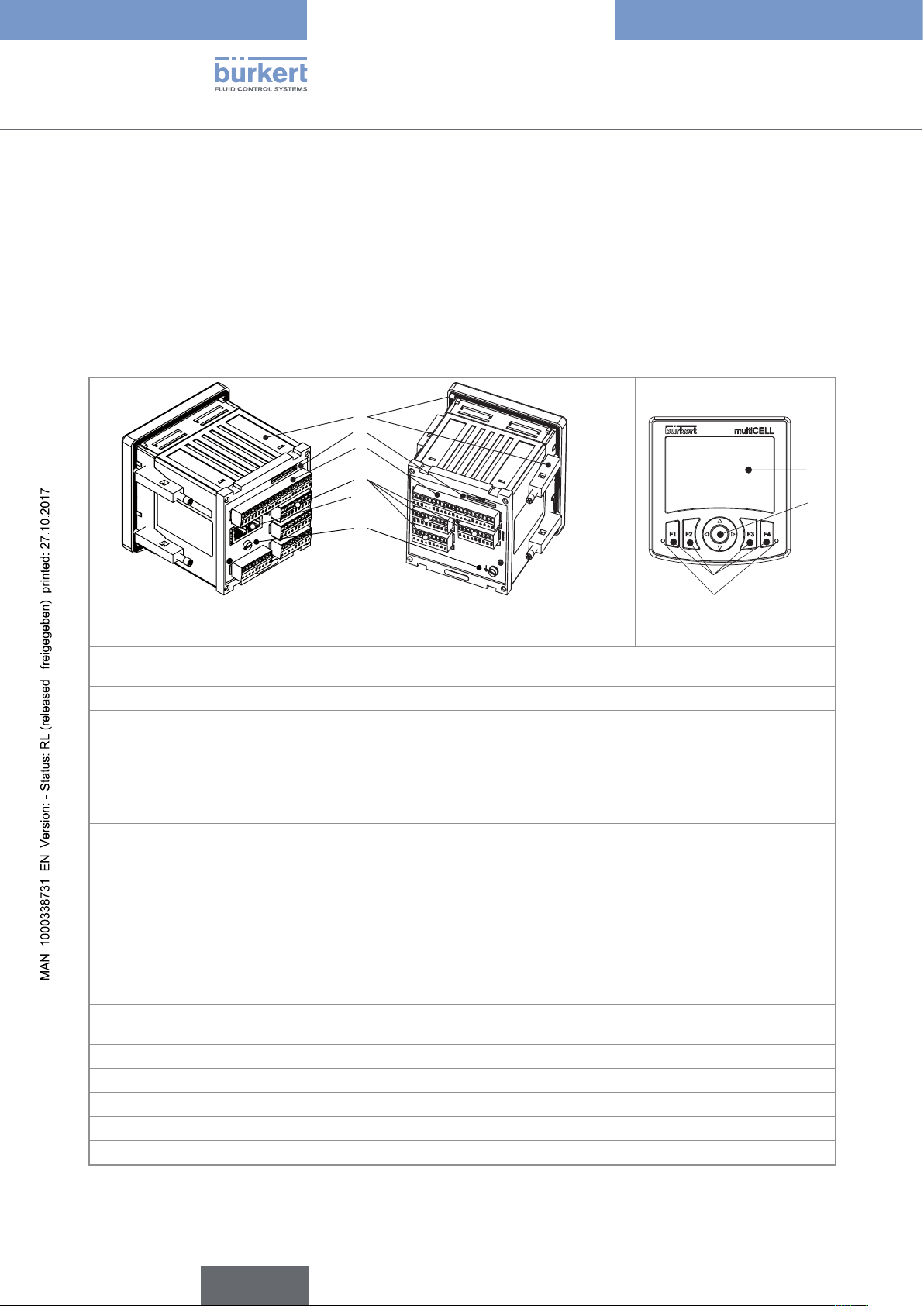
5.2 Construction of a 8619 multiCELL
A
B
C
D
E
G
H
F
J
Device with Ethernet extension
module
Device without Ethernet extension
module
A: Standardised 1/4 DIN housing (92x92 mm) with seal, to be mounted in the door of the electrical enclosure or
cabinet and attached using 4 fasteners
B: Memory card (SD type) reader/recorder
C: Main board (identified by "M0" on the rear plate):
• To connect the electrical power source of the multiCELL
• To power another device, e.g. a flow-rate sensor
• Offering 2 digital inputs (identified by "DI", digital input), two 4...20 mA current outputs (identified by "AO",
analogue output) and 2 digital outputs (identified by "DO", digital output)
D: 1 to 6 slots (4 slots for an Ethernet version) for the extension modules
Possible extension modules:
• Module with light grey connector for connection of a pH sensor or oxidation reduction potential sensor and/or
a temperature sensor
• Module with green connector for connection of a conductivity sensor and/or a temperature sensor
• Module with black connector with two 4...20 mA current outputs and two digital outputs
• Module with orange connector with two analogue inputs and two digital inputs
If a slot is unused, a cap blanks off the opening.
E: Ethernet extension module (if present on the device, always located on slot "M1") with ports for 2 RJ45 con-
nectors (Ethernet version only)
F: Functional earth screw (connected internally to all "FE" terminals on the main board and additional modules)
G: Display with backlight
H: Navigation button (4 directions)
J: 4 dynamic keys
K: 2 LEDs
14
Fig. 1 : Construction of a 8619 multiCELL
A CB
G
L
M
Type 8619
English
Description
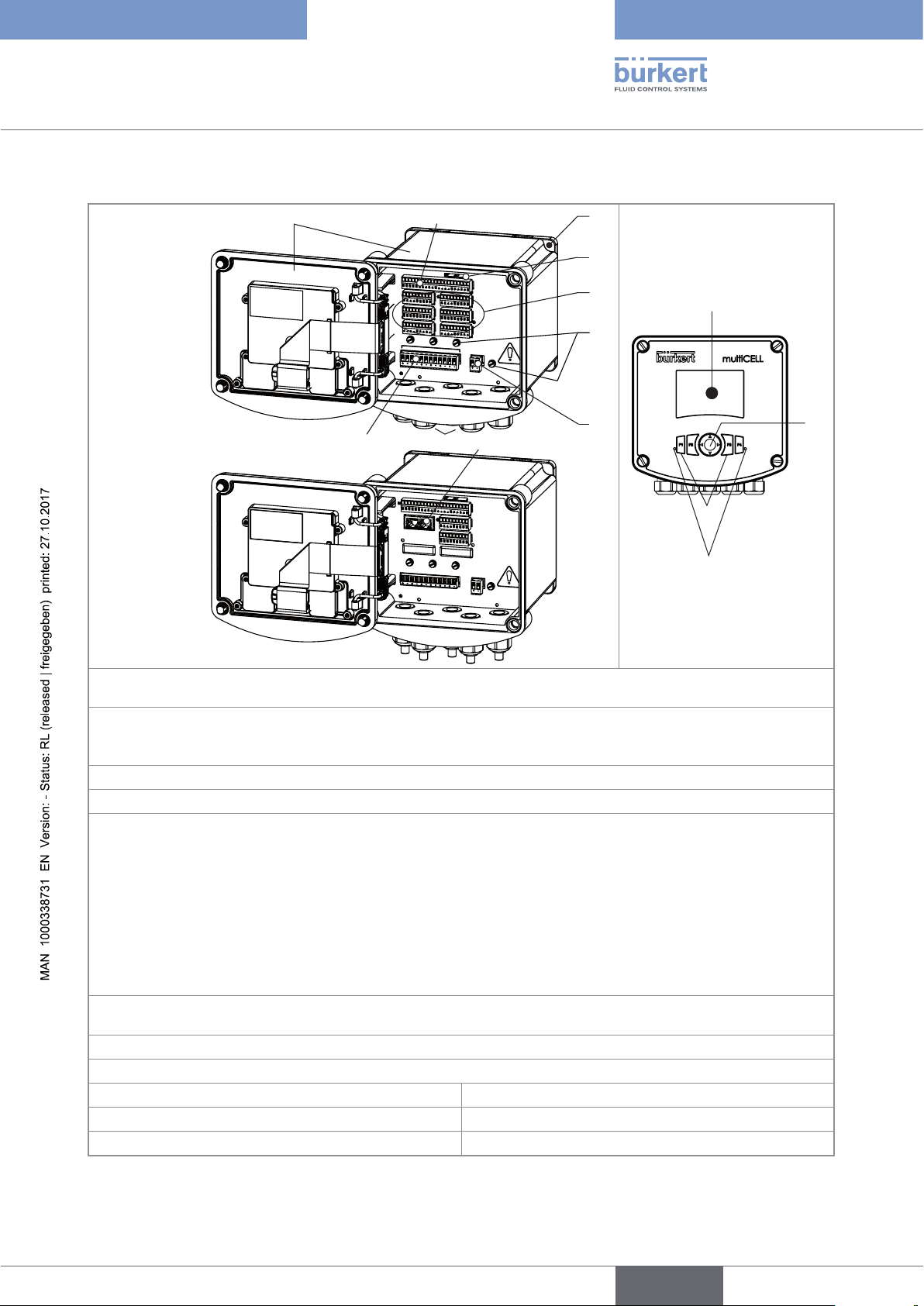
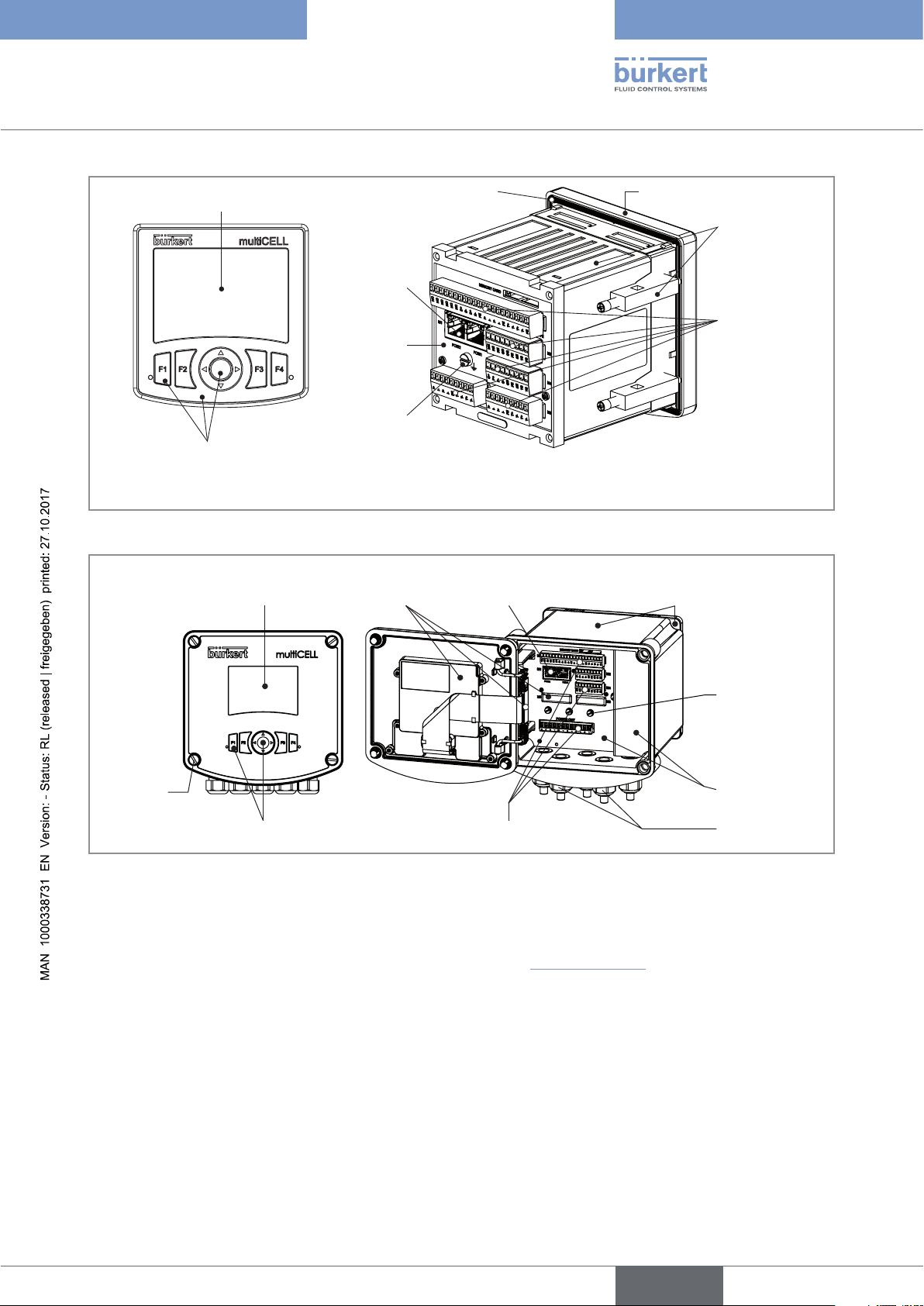
5.3 Construction of a 8619 multiCELL WM DC
D
E
Device without
Ethernet exten-
sion module
M
E
MO
RY
C
ARD
M0
M1
M3
M5
FE
FE
PWR OUT
M2
M4
M6
FE
12-36 V
DC
FE
H
JK
F
M
EMO
RY
C
ARD
Device with
Ethernet exten-
sion module
M1
PORT2
PORT1
M5
FE
FE
PWR OUT
M2
M4
M6
FE
12-36 V
DC
FE
N
O
A: Wall-mounting housing; Cover with seal, closed by 4 screws; Display with navigation button, dynamic keys
and LEDs
B: Main board (identified by "M0" on the plate) with two digital inputs (identified by "DI", digital input), two
4...20 mA current outputs (identified by "AO", analogue output) and two digital outputs (identified by "DO",
digital output)
C: Wall-mounting plate, removable
D: Memory card (SD type) reader/recorder
E: 1 to 6 slots (4 slots for an Ethernet version) for the extension modules
Possible extension modules:
• Module with light grey connector for connection of a pH sensor or oxidation reduction potential sensor and/or
a temperature sensor
• Module with green connector for connection of a conductivity sensor and/or a temperature sensor
• Module with black connector with two 4...20 mA current outputs and two digital outputs
• Module with orange connector with two analogue inputs and two digital inputs
If a slot is unused, a cap blanks off the opening.
F: Ethernet extension module (if present on the device, always located on slot M1) with ports for 2 RJ45 con-
nectors (Ethernet version only)
G: Functional earth screw (connected internally to all "FE" terminals on the main board and additional modules)
H: Connection terminal board for the 12...36 V DC power supply
J: 5 M20 x 1.5 cable glands M: Navigation button (4 directions)
K: Supply and distribution board N: 4 dynamic keys
L: Display with backlight O: 2 LEDs
Fig. 2 : Construction of a 8619 multiCELL WM DC
15
A CB
G
L
M
Type 8619
English
Description
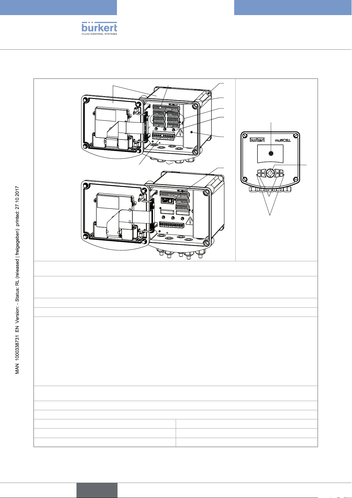
5.4 Construction of a 8619 multiCELL WM AC
D
E
Device without
Ethernet exten-
sion module
M
E
MO
RY
C
ARD
M0
M1
M3
M5
FE
FE
PWR OUT
M2
M4
FE
M6
FE
H
Device with
Ethernet exten-
sion module
JK
M
EMO
RY
C
ARD
M0
M1
PORT2
PORT1
M5
FE
FE
PWR OUT
FE
FE
M2
M4
FE
M6
FE
FE
F
N
O
A: Wall-mounting housing; Cover with seal, closed by 4 screws; Display with navigation button, dynamic keys
and LEDs
B: Main board (identified by "M0" on the plate) with two digital inputs (identified by "DI", digital input), two
4...20 mA current outputs (identified by "AO", analogue output) and two digital outputs (identified by "DO",
digital output)
C: Wall-mounting fastening plate, removable
D: Memory card (SD type) reader/recorder
E: 1 to 6 slots (4 slots for an Ethernet version) for the extension modules
Possible extension modules:
• Module with light grey connector for connection of a pH sensor or oxidation reduction potential sensor and/or
a temperature sensor
• Module with green connector for connection of a conductivity sensor and/or a temperature sensor
• Module with black connector with two 4...20 mA current outputs and two digital outputs
• Module with orange connector with two analogue inputs and two digital inputs
If a slot is unused, a cap blanks off the opening.
F: Ethernet extension module (if present on the device, always located on slot M1) with ports for 2 RJ45 con-
nectors (Ethernet version only)
G: Functional earth screw (connected internally to all "FE" terminals on the main board and additional modules)
H: Protective cap for the terminal block of the 110...240 V AC power supply
J: 5 M20 x 1.5 cable glands M: Navigation button (4 directions)
K: Supply and distribution board N: 4 dynamic keys
L: Display with backlight O: 2 LEDs
16
Fig. 3 : Construction of a 8619 multiCELL WM AC
Type 8619
English
Description
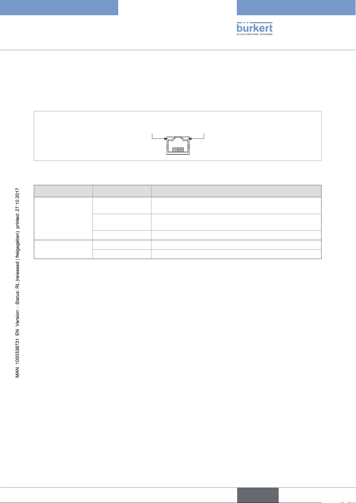
5.5 Description of the LEDs for the connection to the network (Industrial Ethernet only)
An Industrial Ethernet device has 2 LEDs on each RJ45 connector to show the status of the connection to the
network.
Link/Act LED
(yellow)
Fig. 4 : Location of the LEDs of an RJ45 connector
LEDs Behaviour Meaning
ON,
fast blinking
Link/Act LED
(yellow)
Link LED
(green)
Tab. 1 : Description of the LEDs of an RJ45 connector
ON,
slow blinking
OFF No connection to the network.
ON Connection to the network is established.
OFF No connection to the network.
Connection to the parent protocol layer is established. Data are
being exchanged.
No connection to the protocol layer.
Link LED
(green)
17
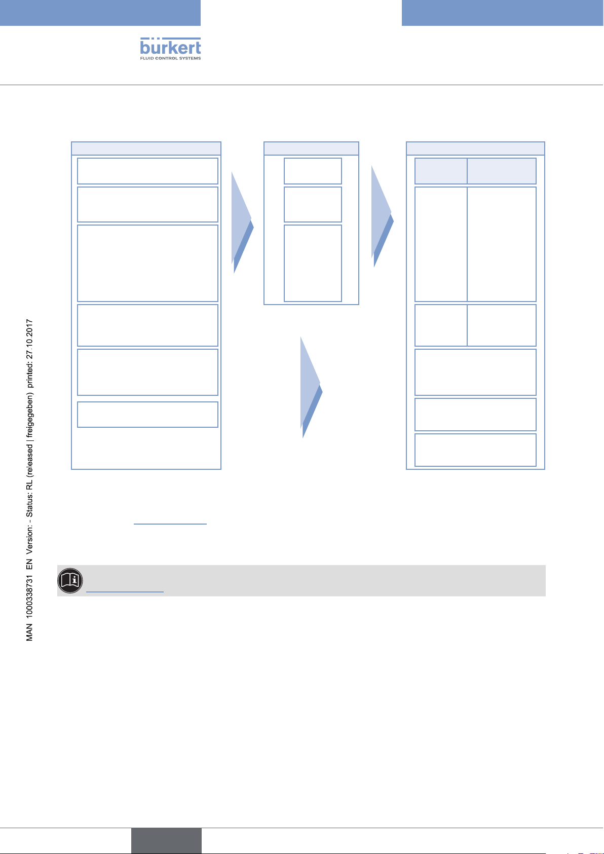
5.6 Functional diagram
English
INPUTS FUNCTIONS 1) OUTPUTS
Digital inputs or frequency
inputs
Type 8619
Description
Function 1 OUTPUT SIGNAL
Analogue inputs,
current or voltage
...
Transistor,
PVN
(process value network)
Conductivity sensor
(2 or 4 electrodes)
2)
Function 12
1 and 2
4...20 mA,
1 and 2
pH/Redox sensor Ethernet data
Temperature sensor
Pt100 / Pt1000
Display
Memory card
PWM or on/
off or PFM or
pulse
4...20 mA
3)
18
1) Simultaneously active
2) PVN: Process value network. Process values coming from a network controller (for example a PLC) via the Ethernet
network (see chap. 8.10.24, page 125)
3) Ethernet data: values coming from the 8619 MultiCELL via the Ethernet network to a network controller (for example a
PLC).
Refer to the supplement related to the Ethernet protocols for the type 8619, available on:
www.burkert.com
Type 8619
English
Description
5.6.1 Arithmetic functions
Availability
Formula
Standard on all models
For all the formulae below, A or B may be the result of another function
• A + B
• A – B
• A / B
• A * B
Use
Operation between two values.
No automatic adjustment of the units!
▶ For the operations "+" (addition) or "–" (subtraction), make sure all the items have the
same units.
▶ For the operations "*" (multiplication) or "/" (division), make sure the unit of the final
result is coherent.
5.6.2 Function MATH
Availability
Formula
Standard on all models
A or B may be the result of another function
Use
α "op
" A "op2" β "op3" B "op4" γ
1
where:
- α, β and γ are constants.
- "op
" is "*"
1
- "op
" is "+" or "–" or "*" or "/"
2
- "op
" is "+" or "–" or "*" or "/"
3
- "op
" is "+" or "–"
4
- The arithmetic operations op
, op2, op3, op4 follow the usual mathematical order (operation
1
order from the left to the right if "*" and "/" are used in the same equation)
Example: (α*A)+(β*B)+γ
Operation between two values.
No automatic adjustment of the units!
▶ For the operations "+" (addition) or "–" (subtraction), make sure all the items have the
same units.
▶ For the operations "*" (multiplication) or "/" (division), make sure the unit of the final
result is coherent.
19
5.6.3 Function PASS
0 %
English
Type 8619
Description
Availability
Formula
Use
Standard on all models
A/B * 100%
Calculation of the passage rate.
5.6.4 Function REJECT
Availability
Formula
Use
Standard on all models
(1 - A/B) * 100 %
Calculation of the rejection rate.
5.6.5 Function DEVIAT
Availability
Formula
Use
Standard on all models
(A/B - 1) * 100 %
Calculation of the deviation rate.
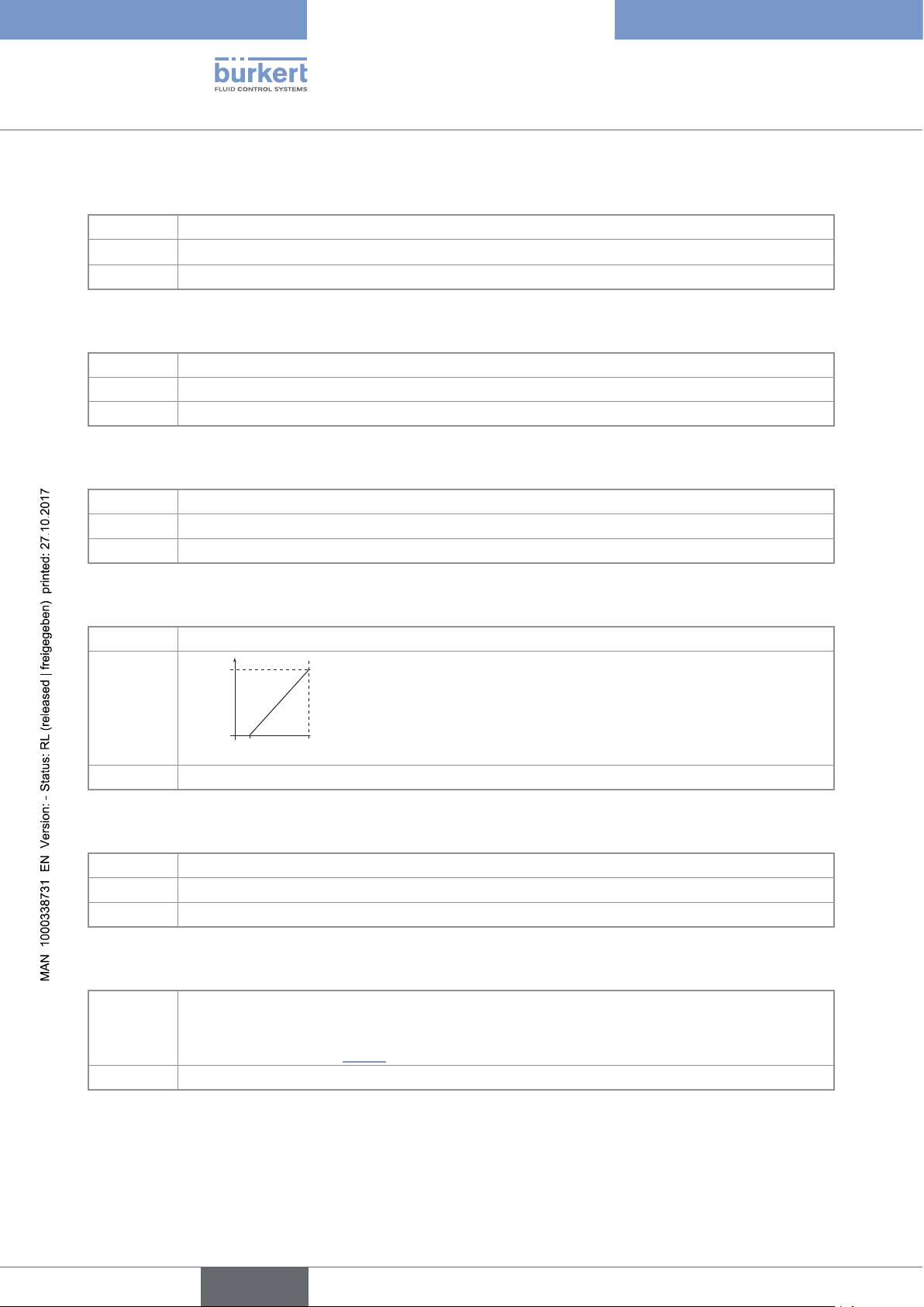
5.6.6 Function PROP (proportional)
Availability
Formula
Standard on all models
100 %
process
parameter
Use
scal- scal+
Calculation of an output proportional to a bounded input.
5.6.7 Function ON/OFF
Availability
Formula
Use
Standard on all models
ON/OFF control
For all input types.
5.6.8 Function "Flow rate measurement"
Availability
Use
• Standard on models 560205, 560213, 565984 to 565987
569259 to 569261, 569268 to 569270, 569277 to 569279
• Optional (see section 8.10.4) on all other models
Each digital input can be used to measure the flow rate.
20
Type 8619
English
Description
5.6.9 Function PID
Availability
Formula
Use
Optional (see section 8.10.4)
Continuous regulation
For all input types; with internal or external setpoint.
5.6.10 Function "Time dosing"
Availability
Use
Optional (see section 8.10.4)
In a cooling tower, for example; used to dose 2 products at fixed intervals or for twice daily dosing
scheduled over one week.
The time dosing function can be combined with an ON/OFF function on a conductivity
measurement only, in order to ensure pre-purging of the system. The "ON/OFF" function must be
configured and activated before the time dosing function.
5.6.11 Function "Volume dosing"
Availability
Use
Optional (see section 8.10.4)
Dedicated to the cooling towers. Metering of a specific volume of water and activation of an
actuator during a specific period in order to add a product and, finally, reset of the water volume
to zero.
5.6.12 Function "Concentration"
Availability
Use
Optional (see section 8.10.4)
The concentration graphs for certain compounds such as NaCl and H2SO4 are memorised for use
over the entire concentration range.
Refer to the technical data sheet of the device, available at: www.burkert.com
5.6.13 Function "Datalogger on memory card"
Availability
Use
Optional (see section 8.10.4)
Option to memorise the variations in 1 to 16 values in a given time interval.
21
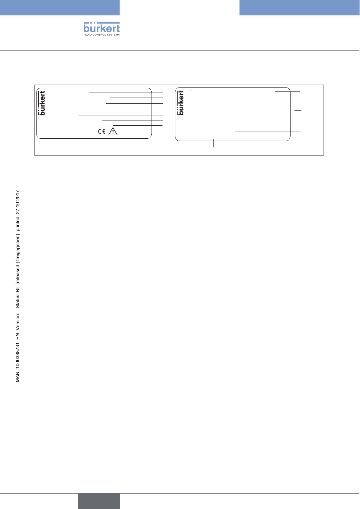
5.7 Description of the rating plate
12
10
}
11
13
English
Type 8619
Description
8619 multiCELL
Supply: 12...36 V DC, 2 A
Temp: -10...+60 °C
IP65 PANEL (FRONT) IP20 (REAR)
Made in France
S-N:1110
00560204
W44ML
Fig. 5 : Description of a rating plate (example)
1
2
3
4
5
6
7
8
M0: 2xDI - 2xAO - 2xDO - SD CARD
M1: pH/ORP - PT100/1000
M2: RES COND 2/4 POLES PT100/1000
M3: 2xAO - 2xDO
Made in France
M4:
M5:
M6:
Softw.:
00560204 W44ML
1. Type of the device
2. Electrical power supply
3. Ambient temperature range
4. Protection rating
5. Serial number
6. Conformity marking
7. Warning: Before using the device, take into account the technical specifications given in the Operating
Instructions.
9
8. Construction code
9. Device fitted with a memory card reader
10. Characteristics of the extension modules
11. Software options
12. Order code
13. Properties of the main board “M0”
22
Type 8619
English
Description
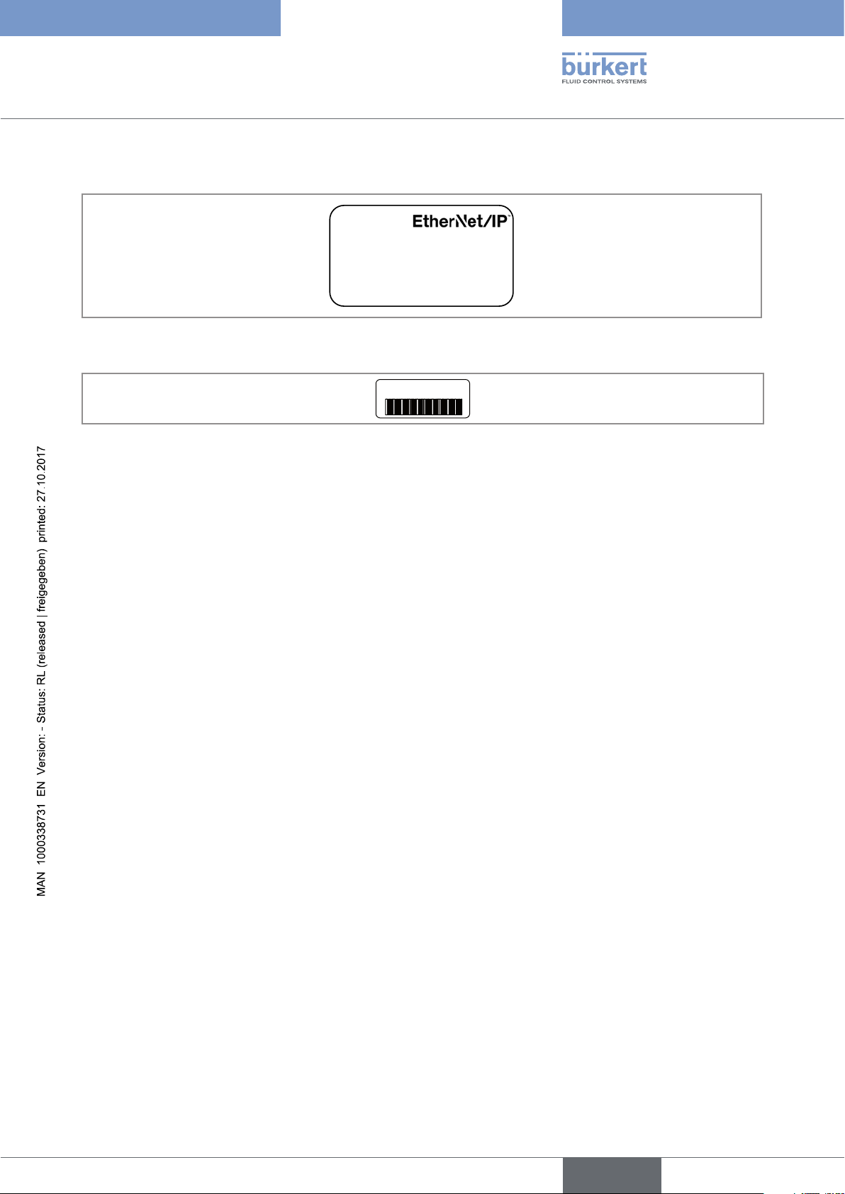
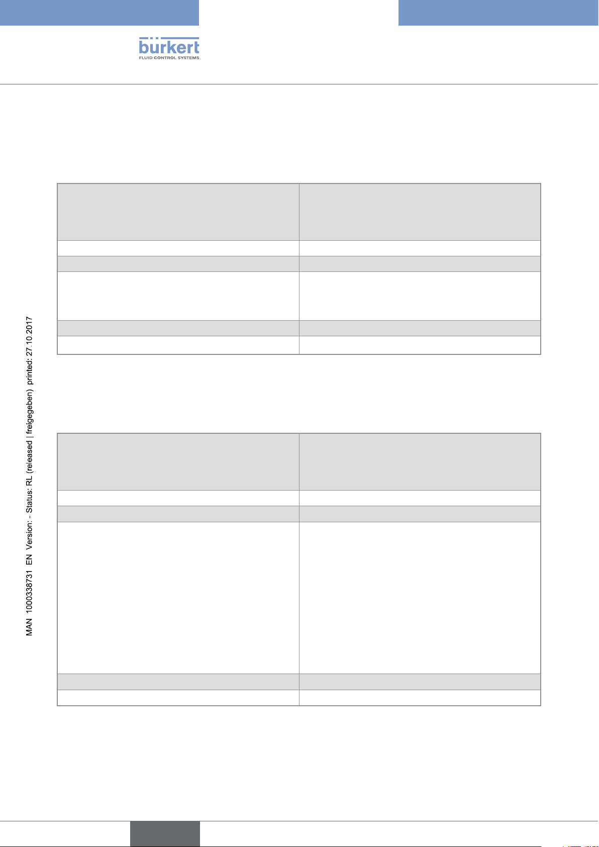
5.7.1 Additional markings (only for an Ethernet version)
Modbus TCP
Fig. 6 : Marking with the protocols (example)
DC-B0-58-FF-FF-FF
Fig. 7 : Marking with the MAC address of the device (example)
23

Type 8619
English
24

Type 8619
English
6 TECHNICAL DATA ...........................................................................................................................................................................26
6.1 Conditions of use of the 8619 multiCELL ............................................................................................................26
6.2 Conditions of use of the 8619 multiCELL WM DC ...........................................................................................26
6.3 Conditions of use of the 8619 multiCELL WM AC ...........................................................................................27
6.4 Compliance to standards and directives ..............................................................................................................27
6.5 Material data .........................................................................................................................................................................28
6.6 Dimensions ...........................................................................................................................................................................29
6.7 Electrical specifications of the 8619 multiCELL ...............................................................................................30
6.8 Electrical specifications of the 8619 multiCELL WM DC ..............................................................................31
6.9 Electrical specifications of the 8619 multiCELL WM AC ..............................................................................32
6.10 Specifications common to all the versions .........................................................................................................33
6.10.1 Specifications of the memory card reader/recorder .................................................................33
6.10.2 Flow rate measurement ...................................................................................................................33
6.10.3 Specifications of the "Input" module ............................................................................................34
6.10.4 Specifications of the output module "OUT" .................................................................................34
6.10.5 Specifications of the "pH/ORP" module .....................................................................................35
6.10.6 Specifications of the conductivity module "COND"...................................................................36
6.10.7 Specifications of the Ethernet module M1 ..................................................................................36
6.11 Specifications of the Industrial Ethernet protocols ........................................................................................37
6.11.1 Modbus TCP protocol ......................................................................................................................37
6.11.2 PROFINET protocol ..........................................................................................................................38
6.11.3 EtherNet/IP protocol .........................................................................................................................39
25
Type 8619
English
Technical data
6 TECHNICAL DATA
6.1 Conditions of use of the 8619 multiCELL
Ambient temperature
• without extension modules
• with extension modules
1)
1)
• –10...+70 °C
• –10...+60 °C
Air humidity < 85%, not condensing
Height above sea level max. 2000 m
Protection rating according to EN 60529 • IP65, NEMA4X on front, once mounted, and elec-
trical enclosure tightly closed
• IP20 for the parts inside the electrical enclosure
Pollution degree Degree 2 according to EN 61010-1
Category of installation Category I according to UL 61010-1
1)
with a memory card available as an accessory (order reference 564072). If a different memory card is used,
observe the operating temperatures given by the manufacturer of the memory card.
6.2 Conditions of use of the 8619 multiCELL WM DC
Ambient temperature
• without extension modules
• with extension modules
Air humidity < 85%, not condensing
Height above sea level max. 2000 m
Protection rating according to EN 60529 IP65, IP67, if the following conditions are met:
1)
1)
• –10...+75 °C
• –10...+60 °C
26
• Body of each cable gland tightened with a torque of
5.5 N·m ± 20% (4,06 lbf·ft ± 20%) at the factory.
• Cable glands blanked off or wired.
• Nut of each cable gland tightened with a torque of
4.5 N·m ± 20% (3,32 lbf·ft ± 20%).
• Housing tightly closed.
• The 4 screws for the cover are tightened crosswise
with a torque of 1.4 N·m ± 20% (1,03 lbf·ft ± 20%).
Pollution degree Degree 2 according to EN 61010-1
Category of installation Category I according to UL 61010-1
1)
with a memory card available as an accessory (order reference 564072). If a different memory card is used,
observe the operating temperatures given by the manufacturer of the memory card.
Type 8619
English
Technical data
6.3 Conditions of use of the 8619 multiCELL WM AC
Observe the maximum permissible load as a function of the ambient temperature.
See the derating curves Fig. 10 chap. 6.9.
Ambient temperature 1) –10...+70 °C
2)
Air humidity < 85%, not condensing
Height above sea level max. 2000 m
Protection rating according to EN 60529 IP65, IP67, if the following conditions are met:
• Body of each cable gland tightened with a torque of
5.5 N·m ± 20% (4,06 lbf·ft ± 20%) at the factory.
• Cable glands blanked off or wired.
• Nut of each cable gland tightened with a torque of
4.5 N·m ± 20% (3,32 lbf·ft ± 20%).
• Housing tightly closed.
• The 4 screws for the cover are tightened crosswise
with a torque of 1.4 N·m ± 20% (1,03 lbf·ft ± 20%).
Pollution degree Degree 3 according to EN 61010-1 if the following
conditions are met:
• Housing tightly closed.
• The 4 screws of the cover are tightened crosswise
at a torque of 1.4 N·m ± 20% (1,03 lbf·ft ± 20%).
Category of installation Category II according to UL 61010-1
1)
with a memory card available as an accessory (order reference 564072). If a different memory card is used,
observe the operating temperatures given by the manufacturer of the memory card.
2)
Refer to the derating curves Fig. 10 chap. 6.9.
6.4 Compliance to standards and directives
The applied standards, which verify conformity with the EU Directives, can be found on the EU Type Examination
Certificate and/or the EU Declaration of Conformity (if applicable).
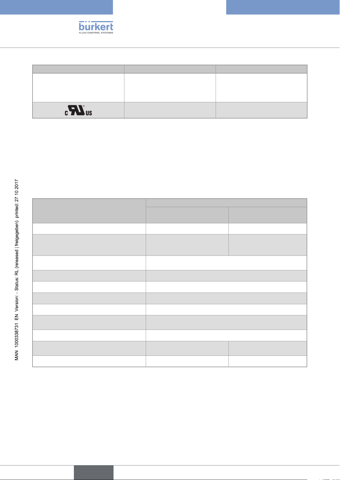
UL certification
Finished devices with variable key PU01 or PU02 are UL-certified devices and comply also with the following
standards:
• UL 61010-1
• CAN/CSA-C22.2 n°61010-1
27
Type 8619
English
Technical data
Identification on the device Certification Variable key
Measuring
®
Equipment
EXXXXXX
UL-listed PU02
UL-recognized PU01
For Ethernet versions, the device is certified by the following certification bodies:
• ODVA for EtherNet/IP protocol,
• PI for PROFINET protocol.
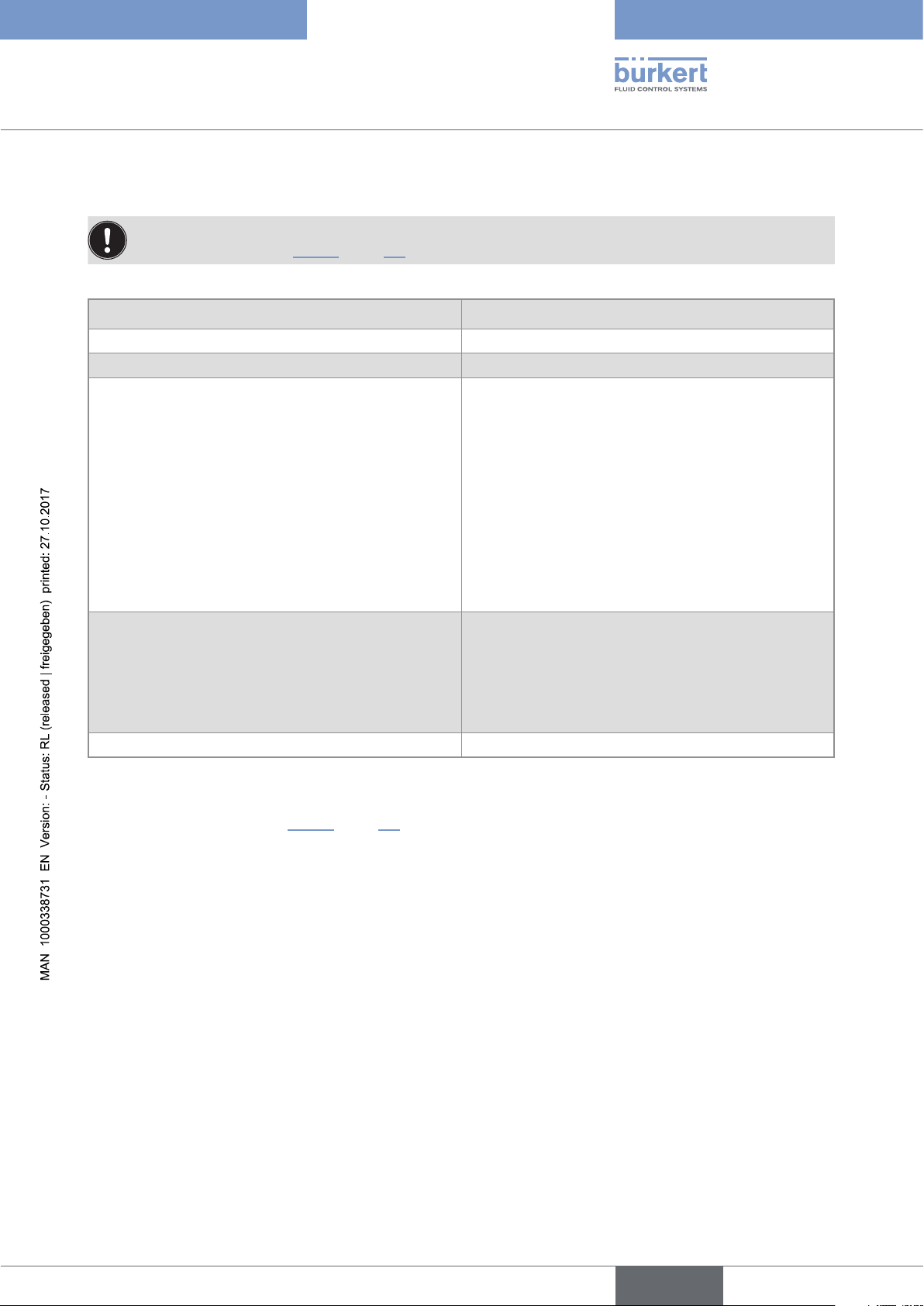
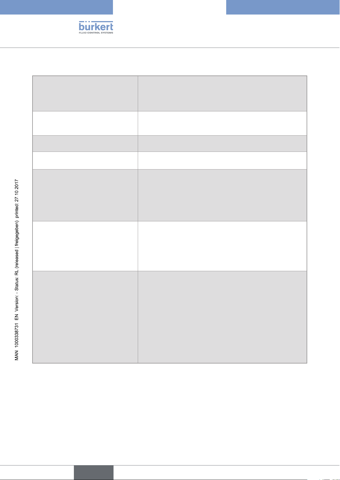
6.5 Material data
Tab. 2 : Materials in contact with the ambient air
Material
Component
8619 multiCELL
Panel-mounting housing and fastener PPO Wall-mounting housing, wall-mounting
fastening plate, cable glands, protective cap
- PA66
(for LCD display), hinge stiffener.
Protective blank (for a slot without
connection terminal)
Seal Silicone
8619 multiCELL WM AC or
8619 multiCELL WM DC
PA66
28
Front panel and keys PC/silicone
Terminal support plate Stainless steel 304
Terminal blocks PBT, contacts in gold-plated copper alloy
Port for an RJ45 connector Housing: copper alloy and thermoplastic
Contacts: gold-plated
Ground screw + spring washer Stainless steel 316 (A4)
Protective cap for the 110...240 V AC power
supply terminal board
- Stainless steel 304
4 cover screws - PVC
Type 8619
English
Technical data
PC
copper alloy, ther-
moplastic, gold-
plated contacts
Stainless steel 304
Stainless steel 316 (A4)
Silicone
Fig. 8 : Component materials of the 8619 multiCELL
PC
PA66
Silicone
copper alloy, thermoplastic,
gold-plated contacts
PC
PPO
PBT, contacts
in gold-plated
copper alloy
PA66
PVC
Silicone
PBT, contacts in gold-plated
copper alloy
Fig. 9 : Component materials of the 8619 multiCELL WM
6.6 Dimensions
Please refer to the technical data sheets of the device, available at: www.burkert.com
Stainless steel 316
(A4)
Stainless steel 304
PA66
29
Type 8619
English
Technical data
6.7 Electrical specifications of the 8619 multiCELL
Electrical supply 12...36 V DC • filtered and regulated
• SELV circuit, at a non-hazardous energy level
• Tolerance: ±10%
• Maximal consumption: 2 A
Specifications of the 12...36 V DC power
source (not provided) of the UL devices,
with variable key PU02
Own consumption (without extension
• Limited power source according to §9.4 of EN 61010-1 standard
• or class 2 source according to UL 1310/1585 and EN 60950-1
standards
1.5 VA
modules, outputs not connected)
Power distribution ("PWR OUT") • 12...36 V DC, 1.8 A max.
• Protected against polarity reversal
All digital inputs ("DI") • Switching threshold V
• Switching threshold V
: 5...36 V DC
on
: < 2 V DC
off
• Input impedance: 3 kW
• Galvanically isolated
• Protected against polarity reversal and voltage spikes
• Frequency: 0.5...2500 Hz
All analogue outputs ("AO") • 4...20 mA current
• Any connection mode, in sink or source mode
• Galvanically isolated
• Protected against polarity reversal
• Max. loop impedance 860 W at 30 V DC, 610 W at 24 V DC,
100 W at 12 V DC
All digital outputs ("DO") • Transistor
• Any connection mode, in NPN or PNP mode
• Galvanically isolated
• Protected against short circuits
• Max. voltage: 36 V DC
• Max. frequency 2000 Hz
• Maximum current consumption allowed:
- Max. 700 mA if 1 DO per module is activated
- Max. 1 A if the 2 DO's per module are activated
- Max. 4 A for an Ethernet version if the device has 4 output
modules
30
 Loading...