

Page 1
Type 0121, 0330, 0331
(0124, 0125, 0332, 0333)
2/2- and 3/2-Way Solenoid Valve
2/2- und 3/2-Wege-Magnetventil
Électrovanne à 2/2 et 3/2 voies
Operating Instructions
Bedienungsanleitung
Manuel d‘utilisation
Page 2
Table of Contents
1 The operating instructions .................................................................................................. 2
2 Authorized use ..............................................................................................................................3
3 Basic safety instructions.......................................................................................................4
4 System description ....................................................................................................................5
5 Technical data................................................................................................................................6
6 Assembly
7 Electrical connection ............................................................................................................10
8 Disassembly
9 Maintenance, troubleshooting .......................................................................................12
10 Transportation, storage, disposal ................................................................................13
...........................................................................................................................................8
.................................................................................................................................12
1 THE OPERATING INSTRUCTIONS
The operating instructions contain important information.
▶▶
Read▶the▶instructions▶carefully▶and▶follow▶the▶safety▶instructions.▶
▶▶ Keep▶the▶instructions▶in▶a▶location▶where▶they▶are▶available▶to▶every▶
user.
The▶liability▶and▶warranty▶for▶the▶device▶are▶void▶if▶the▶operating▶
instructions▶are▶not▶followed.
1.1 Symbols
▶▶ Designates▶instructions▶for▶risk▶prevention.
▶→ Designates▶a▶procedure▶which▶you▶must▶carry▶out.
DANGER!
Immediate▶danger!▶Serious▶or▶fatal▶injuries.
WARNING!
Possible▶danger!▶Serious▶or▶fatal▶injuries.
CAUTION!
Danger!▶Moderate▶or▶minor▶injuries.
2
english
Page 3
NOTE!
Warns of damage to property.
Important▶tips▶and▶recommendations.
Refers▶to▶information▶in▶these▶operating▶instructions▶or▶in▶other▶
documentation.
1.2 Definitions of terms
In▶these▶instructions,▶the▶term▶"device"▶always▶refers▶to▶the▶Type▶0121,▶
0330,▶0331,▶(0124,▶0125,▶0332,▶0333).
2 AUTHORIZED USE
The device is designed to control, shut off and meter neutral
and aggressive media up to a viscosity of 37 mm²/s.
▶▶
Use▶according▶ to▶the▶ authorized▶data,▶ operating▶conditions▶ and▶
conditions▶of▶use▶specified▶in▶the▶contract▶documents▶and▶operating▶instructions.▶
▶▶ Provided▶the▶cable▶plug▶is▶connected▶ and▶ installed▶ correctly,▶e.g.▶
Bürkert▶Type▶2508,▶the▶device▶satisfies▶degree▶of▶protection▶IP65▶
in▶accordance▶with▶DIN▶EN▶60529▶/▶IEC▶60529.
Only operate the device
▶▶
when▶in▶perfect▶condition▶and▶always▶ensure▶proper▶storage,▶transportation,▶installation▶and▶operation.
▶▶ Use▶the▶device▶only▶as▶intended.
2.1 Restrictions
If▶exporting▶the▶device,▶observe▶any▶existing▶restrictions.
english
3
Page 4
3 BASIC SAFETY INSTRUCTIONS
These▶safety▶instructions▶do▶not▶make▶allowance▶for▶any▶contingencies▶
and▶events▶which▶may▶arise▶during▶assembly,▶operation▶and▶maintenance.
Risk of injury from high pressure in the system/device.
▶▶ Before▶working▶on▶the▶system▶or▶device,▶switch▶off▶the▶pressure▶
and▶vent/drain▶lines.
Risk of injury due to electrical shock.
▶▶
Before▶working▶on▶the▶system▶or▶device,▶switch▶off▶the▶power▶supply▶
and▶secure▶to▶prevent▶reactivation.
▶▶ Observe▶applicable▶accident▶prevention▶and▶safety▶regulations▶for▶
electrical▶equipment.
Risk of burns/risk of fire if used for a prolonged switch-on time
through hot device surface.
▶▶
Keep▶device▶away▶from▶highly▶flammable▶substances▶and▶media▶and▶
do▶not▶touch▶with▶bare▶hands.
Risk of injury due to malfunction of valves with alternating
voltage (AC).
Sticking▶core▶causes▶coil▶to▶overheat,▶resulting▶in▶a▶malfunction.
▶▶ Monitor▶process▶to▶ensure▶function▶is▶in▶perfect▶working▶order.
Risk of short-circuit/escape of media through leaking screw
joints.
▶▶
Ensure▶seals▶are▶seated▶correctly.
▶▶ Carefully▶screw▶valve▶and▶pipelines▶together.
4
english
Page 5
General hazardous situations.
To▶prevent▶injuries:
▶▶ In▶a▶potentially▶explosive▶area,▶the▶device▶may▶be▶used▶only▶in▶accor-
dance▶with▶the▶specification▶on▶the▶type▶label.▶For▶the▶use,▶observe▶
the▶supplementary▶instructions▶manual▶enclosed▶with▶the▶device▶with▶
safety▶instructions▶for▶the▶explosion-risk▶area.
▶▶ The▶enclosed▶UL▶instructions▶must▶be▶followed▶in▶the▶UL▶area.
▶▶ Do▶not▶carry▶out▶any▶external▶or▶internal▶modifications▶and▶do▶not▶
subject▶the▶device▶to▶mechanical▶loads▶(e.g.▶by▶placing▶objects▶on▶
it▶or▶standing▶on▶it).▶
▶▶ Secure▶the▶device▶against▶unintentional▶activation.
▶▶ Only▶trained▶technicians▶may▶perform▶installation▶and▶maintenance▶
work.
▶▶
The▶valves▶ must▶be▶ installed▶in▶ accordance▶with▶ the▶regulations▶
applicable▶in▶the▶country.
▶▶ After▶an▶interruption▶in▶the▶power▶supply,▶ensure▶that▶the▶process▶is▶
restarted▶in▶a▶controlled▶manner.
▶▶ Observe▶the▶general▶rules▶of▶technology.
4 SYSTEM DESCRIPTION
4.1 General description
The▶pivoted▶armature▶valves▶are▶direct▶acting▶2/2▶or▶3/2-way▶solenoid▶
valves▶in▶a▶wide▶variety▶of▶circuit▶functions▶and▶models.▶Solenoid▶system▶
and▶media▶ chamber▶are▶ separated▶ from▶ one▶ another▶by▶ a▶separating▶
diaphragm▶system.▶The▶valves▶are▶fast▶acting▶and▶have▶a▶long▶service▶life.
Type▶0121▶▶ ▶2/2▶or▶3/2-way▶solenoid▶valve,▶socket▶connection
Type▶0330▶▶ 2/2▶or▶3/2-way▶solenoid▶valve,▶socket▶connection
Type▶0331▶▶ 2/2▶or▶3/2-way▶solenoid▶valve,▶flange▶connection
Type▶0332▶▶ ▶Bistable▶2/2▶or▶3/2-way▶solenoid▶valve▶▶
with▶2▶coil▶windings,▶socket▶connection
Type▶0333▶▶ ▶Bistable▶2/2▶or▶3/2-way▶solenoid▶valve▶▶
with▶2▶coil▶windings,▶flange▶connection
Type▶0124▶▶ ▶2/2▶or▶3/2-way▶solenoid▶valve,▶socket▶connection
Type▶0125▶▶ ▶2/2▶or▶3/2-way▶solenoid▶valve,▶flange▶connection
english
5
Page 6
5 TECHNICAL DATA
The▶following▶values▶are▶indicated▶on▶the▶type▶label:
•▶Voltage (tolerance▶±10▶%) / current type
•▶Coil power consumption (active▶power▶in▶W▶-▶at▶operating▶
temperature)
•▶Pressure range
•▶Body material (MS=brass,▶VA=stainless▶steel,▶PV=PVC,▶
TE=PTFE,▶PP=polypropylene,▶PD=PVDF)
•▶Seal material▶(F=FKM,▶A=EPDM,▶B=NBR,▶C=FFKM)
5.1 Conformity
The▶Types▶0121,▶0330,▶0331,▶(0124,▶0125,▶0332,▶0333)▶are▶compliant▶
with▶the▶EC▶Directives▶according▶to▶the▶EC▶Declaration▶of▶Conformity.
5.2 Standards
The▶applied▶standards,▶which▶are▶used▶to▶demonstrate▶compliance▶with▶
the▶EC▶Directives,▶are▶listed▶in▶the▶EC▶type▶test▶certificate▶and/or▶the▶EC▶
Declaration▶of▶Conformity.▶
5.3 Operating conditions
Ambient▶temperature▶ ▶
▶ ▶ ▶Type▶0121▶▶ ▶ ▶ ▶ max.▶+50°C▶
Other▶types▶ ▶ ▶ ▶ max.▶+55°C
Duty▶cycle▶
for▶body▶material▶▶
▶ ▶ Brass▶or▶stainless▶steel▶▶ long-term▶operation,▶duty▶cycle▶100%▶
▶ ▶ Plastic▶▶▶ ▶ ▶ ▶ ▶ ▶max.▶permissible▶duty▶cycle▶▶
see▶data▶sheet
Important information for functional reliability.
If▶switched▶off▶for▶a▶long▶period,▶1-2▶switching▶actions▶are▶recommended▶prior▶to▶restart.
Service▶life▶
High▶switching▶frequency▶and▶high▶pressures▶reduce▶the▶service▶life.
Degree▶of▶protection▶ ▶ ▶ ▶IP65▶in▶accordance▶with▶DIN▶EN▶60529▶
/▶IEC▶60529▶with▶correctly▶connected▶
and▶installed▶cable▶plug,▶e.g.▶Bürkert▶
Type▶2508
6
english
Page 7
5.4 Mechanical data
2 (A)
1 (P)
2 (A)
1 (P)
2(A)
1(P) 3(R)
4(B)
1(P) 3(R)
2(A)
1(P) 3(R)
2(A) 4(B)
2(A)
1(P) 3(R)
Dimensions▶ ▶ ▶ see▶data▶sheet
Coil▶material▶ ▶ ▶ epoxide
Connections▶ ▶ ▶ ▶G▶1/4▶▶
(NPT▶1/4,▶G▶1/8,▶G▶3/8,▶Rc▶1/4▶on▶request)
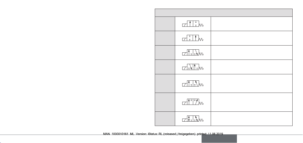
Circuit▶functions
A▶
(NC)
B▶
(NO)
2/2-way▶valve,▶▶
closed▶in▶rest▶position
2/2-way▶valve,▶▶
open▶in▶rest▶position
5.5 Fluidic data
Media▶ ▶ ▶ ▶ ▶ ▶aggressive,▶neutral,▶gaseous▶and▶liquid▶media,▶▶
which▶do▶not▶attack▶body▶and▶seal▶materials.▶
(see▶resistance▶table▶at▶www.buerkert.de).
Medium▶temperature▶for▶seal▶material▶
▶ ▶ ▶FKM▶ ▶ ▶ ▶ 0▶°C▶–▶+90▶°C▶
EPDM▶ ▶ ▶ ▶ -30▶°C▶–▶+▶90▶°C▶
NBR▶ ▶ ▶ ▶ 0▶°C▶–▶+▶80▶°C▶
FFKM▶ ▶ ▶ ▶ +5▶°C▶–▶+90▶°C
C▶
(NC)
D▶
(NO)
E
F
T
1(P)
3/2-way▶valve;▶closed▶in▶rest▶position,▶
output▶A▶unloaded
3/2-way▶valve,▶in▶rest▶position,▶output▶B▶
pressurized
3/2-way▶mixing▶valve;▶in▶rest▶position,▶
pressure▶connection▶P2▶connected▶to▶
output▶A,▶P1▶closed
3/2-way▶distribution▶valve,▶
in▶rest▶position,▶pressure▶connection▶P▶
connected▶to▶output▶B
3/2-way▶all▶purpose▶valve
english
7
Page 8
5.6 Electrical data
Connections▶ ▶ ▶ ▶DIN▶EN▶175301-803▶(DIN▶43▶650),▶shape▶A▶for▶
cable▶plug▶Type▶2508▶or▶2509
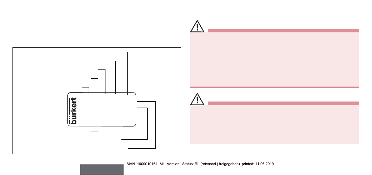
5.7 Type label
Body▶material
Seal▶material
Orifice
Circuit▶function
Type
0330▶C▶▶2.0▶▶FKM▶▶MS▶
G1/4▶▶▶▶▶▶▶▶▶▶▶▶▶▶▶0-6▶bar▶
24V▶DC▶▶▶▶▶▶▶▶▶▶▶▶▶▶▶▶▶8W
CE
00450000
Made▶in▶Germany
Identification▶number
Voltage,▶frequency,▶output
Port▶connection,▶nominal▶pressure
Fig. 1: Description of the type label (example)
W14UN
6 ASSEMBLY
DANGER!
Risk of injury from high pressure in the system/device.
▶▶
Before▶working▶on▶the▶system▶or▶device,▶switch▶off▶the▶pressure▶
and▶vent/drain▶lines.
Risk of injury due to electrical shock.
▶▶
Before▶working▶on▶the▶system▶or▶device,▶switch▶off▶the▶power▶supply▶and▶secure▶to▶prevent▶reactivation.
▶▶ Observe▶applicable▶accident▶prevention▶and▶safety▶regulations▶for▶
electrical▶equipment.
WARNING!
Risk of injury from improper assembly.
▶▶
The▶assembly▶may▶be▶carried▶out▶only▶by▶trained▶technicians▶and▶
with▶the▶appropriate▶tools.
▶▶ Secure▶system▶against▶unintentional▶activation.
▶▶ Following▶assembly,▶ensure▶a▶controlled▶restart.
8
english
Page 9
6.1 Before installation
Installation position:
The▶installation▶position▶is▶optional.▶Preferably:▶Actuator▶at▶the▶top.
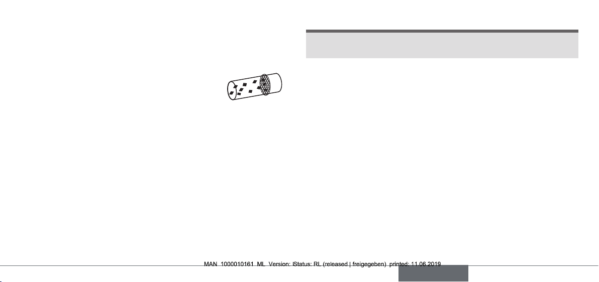
▶→ Prior▶to▶installation▶check▶pipelines▶for▶dirt▶and▶clean▶if▶necessary.
Dirt filter:▶To▶ensure▶that▶the▶solenoid▶valve▶functions▶reliably,▶a▶dirt▶filter▶(≤▶500▶µm)▶must▶be▶
installed▶in▶front▶of▶the▶valve▶input.
6.2 Installation
▶→ Observe▶flow▶direction:▶▶
Functioning▶of▶the▶device▶is▶only▶ensured▶if▶the▶circuit▶function▶is▶
maintained.
Deviceswith socket connection
▶→ Use▶PTFE▶tape▶as▶seal▶material.
▶→ Determine▶the▶maximum▶screw-in▶depth▶of▶the▶connecting▶threads▶
as▶this▶does▶not▶comply▶with▶any▶standard.
NOTE!
Caution risk of breakage.
Do▶not▶use▶the▶coil▶as▶a▶lifting▶arm.
▶▶
▶→ Hold▶the▶device▶with▶a▶suitable▶tool▶(open-end▶wrench)▶on▶the▶
body;▶screw▶into▶the▶pipeline.
Attaching▶the▶device:
▶→ Via▶bore▶holes▶M4x8▶(made▶from▶brass▶or▶stainless▶steel)▶or▶self-
tapping▶screws▶3.9▶DIN▶7970▶(made▶from▶plastic,▶max.▶screw-in▶
depth▶10▶mm)▶on▶the▶bottom▶side▶of▶the▶body▶at▶drill▶pattern▶
38x24.
Devices in flange model
Attaching▶the▶device:
▶→ Via▶supplied▶screws▶on▶basic▶devices▶or▶manifold.
▶→ Tighten▶fastening▶screws▶on▶the▶coil▶to▶a▶maximum▶torque▶of▶2▶Nm.
english
9
Page 10
6.3 Manual control
2
NOTE!
When▶ the▶ manual▶control▶is▶locked,▶the▶valve▶ cannot▶be▶actuated▶
▶▶
electrically.
Manual▶control
Press
Turn
Fig. 2: Manual control
1
7 ELECTRICAL CONNECTION
DANGER!
Risk of injury due to electrical shock.
▶▶
Before▶working▶on▶the▶system▶or▶device,▶switch▶off▶the▶power▶sup-
ply▶and▶secure▶to▶prevent▶reactivation.
▶▶ Observe▶applicable▶accident▶prevention▶and▶safety▶regulations▶for▶
electrical▶equipment.
If the protective conductor is not connected, there is a risk of
electric shock.
▶▶
Always▶connect▶protective▶conductor▶and▶check▶electrical▶continuity▶
between▶coil▶and▶housing.
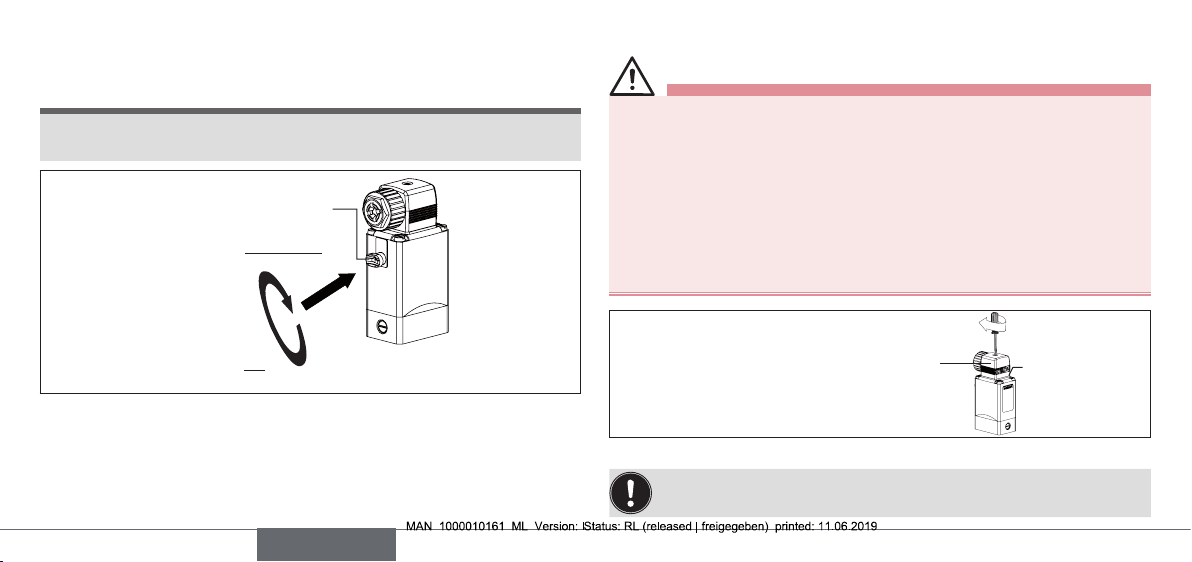
max.▶1▶Nm
Approved▶cable▶plug,▶e.g.▶Type▶
2508▶or▶other▶suitable▶cable▶plug▶
in▶accordance▶with▶▶
DIN▶EN▶175301-803▶shape▶A
Fig. 3: Connecting the cable plug to the power supply
Note▶the▶voltage▶and▶current▶type▶as▶specified▶on▶the▶type▶label.
Seal
10
english
Page 11
7.1 Standard model
▶→ Connect▶L1/+▶ and▶ N/–▶ to▶ terminals▶1▶ and▶ 2,▶independent▶ of▶the▶
polarity.
▶→ Connect▶protective▶conductor.
▶→ Attach▶seal▶and▶check▶for▶correct▶fit.
▶→ Tighten▶cable▶plug▶(Type▶2508▶or▶2509▶in▶accordance▶with▶DIN▶EN▶
175301-803▶(DIN▶43▶650),▶shape▶A,▶for▶order▶numbers▶ see▶data▶
sheet);▶while▶doing▶so,▶observe▶the▶maximum▶torque▶of▶1▶Nm.
▶→ Check▶electrical▶continuity▶between▶coil▶and▶body▶(protective▶con-
ductor▶function).
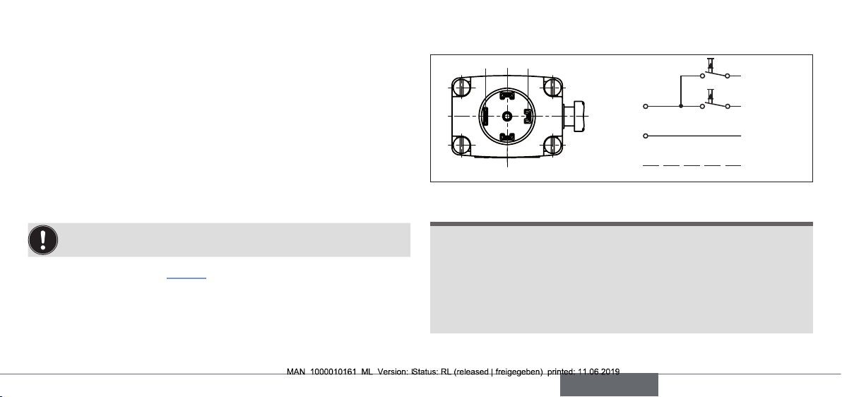
7.2 Pulse model (CF 02)
In▶accordance▶with▶the▶terminals▶on▶the▶valves,▶the▶connection▶
terminals▶in▶the▶cable▶plug▶are▶marked▶with▶the▶numbers▶1▶to▶3.
▶→ Connect▶as▶shown▶in▶“Fig.▶4”.▶Pulse▶on▶terminal▶1▶closes▶the▶valve;▶
pulse▶on▶terminal▶2▶opens▶the▶valve.
▶→ Attach▶seal▶and▶check▶for▶correct▶fit.
▶→ Tighten▶cable▶plug▶(Type▶2508▶or▶2509▶in▶accordance▶with▶DIN▶EN▶
175301-803▶(DIN▶43▶650),▶shape▶A,▶for▶order▶numbers▶ see▶data▶
sheet);▶while▶doing▶so,▶observe▶the▶maximum▶torque▶of▶1▶Nm.
▶→ Check▶electrical▶continuity▶between▶coil▶and▶body▶(protective▶con-
ductor▶function).
24 3
(=)▶∼
(+)▶L1
(–)▶N
1
Fig. 4: Electrical connection - pulse model (CF 02)
NOTE!
Prevent▶simultaneous▶pulsing▶on▶both▶coil▶windings.
▶▶
▶▶ Parallel▶to▶the▶ terminals,▶ no▶other▶consumers▶ (relay,▶etc.)▶ may▶ be▶
connected.
▶▶
The▶respective▶coil▶connection▶that▶does▶not▶carry▶current▶must▶be▶
galvanically▶isolated▶(open).
▶▶ In▶case▶two▶or▶more▶valves▶are▶connected▶in▶parallel,▶the▶use▶of▶two-
pole▶or▶multi-pole▶switches▶must▶ensure▶that▶this▶requirement▶is▶met.
PE
Terminal▶1
Terminal▶2
Terminal▶3
Protective▶
conductor
english
11
Page 12
8 DISASSEMBLY
DANGER!
Risk of injury from high pressure in the system/device.
▶▶
Before▶working▶on▶the▶system▶or▶device,▶switch▶off▶the▶pressure▶
and▶vent/drain▶lines.
Risk of injury due to electrical shock.
▶▶
Before▶working▶on▶the▶system▶or▶device,▶switch▶off▶the▶power▶
supply▶and▶secure▶to▶prevent▶reactivation.
▶▶ Observe▶applicable▶accident▶prevention▶and▶safety▶regulations▶
for▶electrical▶equipment.
WARNING!
Risk of injury from improper disassembly.
▶▶
Disassembly▶may▶be▶carried▶out▶only▶by▶trained▶technicians▶and▶
with▶the▶appropriate▶tools.
Risk of injury from hazardous media.
▶▶
Before▶loosening▶lines▶or▶valves,▶flush▶out▶hazardous▶media,▶
depressurize▶and▶drain▶the▶lines.
9 MAINTENANCE, TROUBLESHOOTING
9.1 Safety instructions
DANGER!
Risk of injury from high pressure in the system.
▶▶
Turn▶off▶the▶pressure▶and▶vent▶the▶lines▶before▶loosening▶lines▶or▶
valves.
Risk of injury due to electrical shock.
▶▶
Before▶working▶on▶the▶system▶or▶device,▶switch▶off▶the▶power▶
supply▶and▶secure▶to▶prevent▶reactivation.
▶▶ Observe▶applicable▶accident▶prevention▶and▶safety▶regulations▶
for▶electrical▶equipment.
WARNING!
Risk of injury from improper maintenance work.
▶▶
Maintenance▶may▶be▶carried▶out▶only▶by▶trained▶technicians▶and▶
with▶the▶appropriate▶tools.
▶▶ Secure▶system▶against▶unintentional▶activation.
▶▶ Following▶maintenance,▶ensure▶a▶controlled▶restart.
12
english
Page 13

9.2 Malfunctions
If▶malfunctions▶occur,▶check▶whether:
▶→ the▶device▶has▶been▶installed▶according▶to▶the▶instructions,
▶→ the▶electrical▶and▶fluid▶connections▶are▶correct,
▶→ the▶device▶is▶not▶damaged,
▶→ all▶screws▶have▶been▶tightened,
▶→ the▶voltage▶and▶pressure▶have▶been▶switched▶on,
▶→ the▶pipelines▶are▶clean.
Malfunction Possible cause
Valve▶does▶not▶
switch
Valve▶does▶not▶close Inner▶compartment▶of▶the▶valve▶is▶dirty
9.2.1 Repairs
Repairs▶may▶only▶be▶carried▶out▶by▶the▶manufacturer.▶Operating▶data▶
may▶change▶if▶spare▶parts▶are▶replaced▶by▶the▶user.
Short▶circuit▶or▶coil▶interrupted
Medium▶pressure▶outside▶the▶permitted▶
pressure▶range
Manual▶control▶locked
Manual▶control▶locked
10 TRANSPORTATION, STORAGE,
DISPOSAL
NOTE!
Transport damage.
Inadequately▶protected▶devices▶may▶be▶damaged▶during▶
transportation.
Protect▶the▶ device▶against▶ moisture▶and▶ dirt▶in▶ shock-resistant▶
▶▶
packaging▶during▶transportation.▶
▶▶ Prevent▶the▶temperature▶from▶ exceeding▶ or▶ dropping▶ below▶ the▶
permitted▶storage▶temperature.
Incorrect storage may damage the device.
Store▶the▶device▶in▶a▶dry▶and▶dust-free▶location.
▶▶
▶▶ Storage▶temperature▶-40▶–▶+80°C.▶
Damage to the environment caused by parts contaminated
with media.
Dispose▶of▶the▶device▶and▶packaging▶in▶an▶environmentally▶friendly▶
▶▶
manner.
▶▶
Observe▶applicable▶disposal▶and▶environmental▶regulations.
english
13
Page 14

Inhaltsverzeichnis
1 Die Bedienungsanleitung .................................................................................................14
2 Bestimmungsgemäße Verwendung .........................................................................15
3 Grundlegende Sicherheitshinweise .........................................................................16
4 Systembeschreibung
5 Technische Daten....................................................................................................................18
6 Montage
7 Elektrischer Anschluss........................................................................................................22
8 Demontage
9 Wartung, Fehlerbehebung ................................................................................................24
10 Transport, Lagerung, Entsorgung ...............................................................................25
...................................................................................................................................................20
...................................................................................................................................24
............................................................................................................17
1 DIE BEDIENUNGSANLEITUNG
Die Bedienungsanleitung enthält wichtige Informationen.
▶▶
Anleitung▶sorgfältig▶lesen▶und▶die▶Hinweise▶zur▶Sicherheit▶beachten.▶
▶▶ Anleitung▶so▶aufbewahren,▶dass▶sie▶jedem▶Benutzer▶zur▶ Verfügung▶
steht.
Die▶Haftung▶und▶Gewährleistung▶für▶das▶Gerät▶entfällt,▶wenn▶die▶
Anweisungen▶der▶Bedienungsanleitung▶nicht▶beachtet▶werden.
1.1 Darstellungsmittel
▶▶ markiert▶eine▶Anweisung▶zur▶Gefahrenvermeidung.
▶→ markiert▶einen▶Arbeitsschritt▶den▶Sie▶ausführen▶müssen.
GEFAHR!
Unmittelbare▶Gefahr!▶Schwere▶oder▶tödliche▶Verletzungen.
WARNUNG!
Mögliche▶Gefahr!▶Schwere▶oder▶tödliche▶Verletzungen.
VORSICHT!
Gefahr!▶Mittelschwere▶oder▶leichte▶Verletzungen.
14
deutsch
Page 15

HINWEIS!
Warnt vor Sachschäden.
Wichtige▶Tipps▶und▶Empfehlungen.
verweist▶auf▶Informationen▶in▶dieser▶Bedienungsanleitung▶oder▶
in▶anderen▶Dokumentationen.
1.2 Begriffsdefinition
Der▶in▶dieser▶Anleitung▶verwendete▶Begriff▶„Gerät“▶steht▶immer▶für▶Typ▶
0121,▶0330,▶0331,▶(0124,▶0125,▶0332,▶0333).
2 BESTIMMUNGSGEMÄSSE
VERWENDUNG
Das Gerät ist zum Steuern, Absperren und Dosieren von neutralen und aggressiven Medien bis zu einer Viskosität von 37
mm²/s konzipiert.
▶▶
Für▶den▶Einsatz▶die▶in▶den▶Vertragsdokumenten▶und▶der▶Bedienungs-
anleitung▶spezifizierten▶zulässigen▶Daten,▶Betriebs-▶und▶Einsatzbe-
dingungen▶beachten.▶
▶▶ Mit▶einer▶sachgemäß▶angeschlossenen▶und▶montierten▶Gerätesteck-
dose,▶z.▶B.▶Bürkert▶Typ▶2508▶erfüllt▶das▶Gerät▶die▶Schutzart▶IP65▶nach▶
DIN▶EN▶60529▶/▶IEC▶60529.
Das Gerät
▶▶
nur▶in▶einwandfreiem▶Zustand▶betreiben▶und▶auf▶sachgerechte▶Lage-
rung,▶Transport,▶Installation▶und▶Bedienung▶achten.
▶▶ nur▶bestimmungsgemäß▶verwenden.
2.1 Beschränkungen
Bei▶der▶Ausfuhr▶des▶Geräts▶gegebenenfalls▶bestehende▶Beschränkungen▶
beachten.
deutsch
15
Page 16

3 GRUNDLEGENDE
SICHERHEITSHINWEISE
Diese▶Sicherheitshinweise▶ berücksichtigen▶keine▶ Zufälligkeiten▶und▶
Ereignisse,▶die▶bei▶Montage,▶Betrieb▶und▶Wartung▶auftreten▶können.
Verletzungsgefahr durch hohen Druck in Anlage/Gerät.
▶▶ Vor▶Arbeiten▶an▶Anlage▶oder▶Gerät,▶den▶Druck▶abschalten▶und▶
Leitungen▶entlüften/entleeren.
Verletzungsgefahr durch Stromschlag.
▶▶
Vor▶Arbeiten▶an▶Anlage▶oder▶Gerät,▶die▶Spannung▶abschalten▶und▶
vor▶Wiedereinschalten▶sichern.
▶▶ Die▶geltenden▶Unfallverhütungs-▶und▶Sicherheitsbestimmungen▶für▶
elektrische▶Geräte▶beachten.
Verbrennungsgefahr/Brandgefahr bei längerer Einschaltzeit
durch heiße Geräteoberfläche.
▶▶
Gerät▶von▶leicht▶brennbaren▶Stoffen▶und▶Medien▶fernhalten▶und▶nicht ▶
mit▶bloßen▶Händen▶berühren.
Verletzungsgefahr durch Funktionsausfall bei Ventilen mit
Wechselspannung (AC).
Festsitzender▶Kern▶bewirkt▶Spulenüberhitzung,▶die▶zu▶Funktionsausfall▶führt.
▶▶ Arbeitsprozess▶auf▶einwandfreie▶Funktion▶überwachen.
Kurzschlussgefahr/Austritt von Medium durch undichte
Verschraubungen.
▶▶
Auf▶einwandfreien▶Sitz▶der▶Dichtungen▶achten.
▶▶ Ventil▶und▶Rohrleitungen▶sorgfältig▶verschrauben.
16
deutsch
Page 17

Allgemeine Gefahrensituationen.
Zum▶Schutz▶vor▶Verletzungen▶ist▶zu▶beachten:
▶▶ Im▶explosionsgefährdeten▶Bereich▶darf▶das▶Gerät▶nur▶entsprechend▶
der▶Spezifikation▶ auf▶dem▶ Typschild▶eingesetzt▶ werden.▶Für▶ den▶
Einsatz▶muss▶die▶dem▶Gerät▶beiliegende▶Zusatzanleitung▶mit▶Sicher-
heitshinweisen▶für▶den▶Ex-Bereich▶beachtet▶werden.
▶▶ Im▶UL-Bereich▶muss▶die▶beiliegende▶UL-Anleitung▶beachtet▶werden.
▶▶ Am▶Gerät▶keine▶inneren▶oder▶äußeren▶Veränderungen▶vornehmen▶
und▶nicht▶mechanisch▶belasten▶(z.▶B.▶durch▶Ablage▶von▶Gegen-
ständen▶oder▶als▶Trittstufe).▶
▶▶ Vor▶unbeabsichtigem▶Betätigen▶sichern.
▶▶ Nur▶geschultes▶Fachpersonal▶darf▶Installations-▶und▶Instandhaltungs-
arbeiten▶ausführen.
▶▶ Die▶Ventile▶müssen▶gemäß▶der▶im▶Land▶gültigen▶Vorschriften▶installiert▶
werden.
▶▶
Nach▶Unterbrechung▶der▶elektrischen▶Versorgung▶für▶einen▶kontrol-
lierten▶Wiederanlauf▶des▶Prozesses▶sorgen.
▶▶ Die▶allgemeinen▶Regeln▶der▶Technik▶einhalten.
4 SYSTEMBESCHREIBUNG
4.1 Allgemeine Beschreibung
Die▶Klappankerventile▶ sind▶ein▶ direktwirkende▶2/2-▶ oder▶ 3/2-WegeMagnetventile▶in▶ vielfältigen▶Wirkungsweisen▶ und▶Ausführungen.▶
Magnetsystem▶und▶Mediumsraum▶sind▶durch▶ein▶Trennmembransystem▶
voneinander▶getrennt.▶Die▶Ventile▶sind▶schnellschaltend▶und▶haben▶eine▶
hohe▶Lebensdauer.
Typ▶0121▶ ▶ ▶2/2-▶oder▶3/2-Wege-Magnetventil,▶Muffenanschluss
Typ▶0330▶ ▶ 2/2-▶oder▶3/2-Wege-Magnetventil,▶Muffenanschluss
Typ▶0331▶ ▶ 2/2-▶oder▶3/2-Wege-Magnetventil,▶Flanschanschluss
Typ▶0332▶ ▶ ▶Bistabiles▶2/2-▶oder▶3/2-Wege-Magnetventil▶▶
mit▶2▶Spulenwicklungen,▶Muffenanschluss
Typ▶0333▶ ▶ ▶Bistabiles▶2/2-▶oder▶3/2-Wege-Magnetventil▶▶
mit▶2▶Spulenwicklungen,▶Flanschanschluss
Typ▶0124▶ ▶ ▶2/2-▶oder▶3/2-Wege-Magnetventil,▶Muffenanschluss
Typ▶0125▶ ▶ ▶2/2-▶oder▶3/2-Wege-Magnetventil,▶Flanschanschluss
deutsch
17
Page 18

5 TECHNISCHE DATEN
Folgende▶Werte▶sind▶auf▶dem▶Typschild▶angegeben:
•▶Spannung (Toleranz▶±10▶%) / Stromart
•▶Spulenleistung (Wirkleistung▶in▶W▶-▶betriebswarm)
•▶Druckbereich
•▶Gehäusewerkstoff (MS=Messing,▶VA=Edelstahl,▶PV=PVC,▶
TE=PTFE,▶PP=Polypropylen,▶PD=PVDF)
•▶Dichtwerkstoff▶(F=FKM,▶A=EPDM,▶B=NBR,▶C=FFKM)
5.1 Konformität
Die▶Typen▶0121,▶0330,▶0331,▶(0124,▶0125,▶0332,▶0333)▶sind▶konform▶zu▶
den▶EG-Richtlinien▶entsprechend▶der▶EG-Konformitätserklärung.
5.2 Normen
Die▶angewandten▶Normen,▶mit▶welchen▶die▶Konformität▶zu▶den▶Richtlinien▶
nachgewiesen▶wird,▶sind▶in▶der▶EG-Baumusterprüfbescheinigung▶und/
oder▶der▶EG-Konformitätserklärung▶nachzulesen.▶
5.3 Betriebsbedingungen
Umgebungstemperatur▶ ▶
▶ ▶ ▶Typ▶0121▶ ▶ ▶ ▶ ▶ ▶ max.▶+50°C▶
andere▶Typen▶ ▶ ▶ ▶ ▶ max.▶+55°C
Einschaltdauer▶
bei▶Gehäusewerkstoff▶▶
▶ ▶ Messing▶oder▶Edelstahl▶▶ ▶ Dauerbetrieb▶100%▶ED▶
▶ ▶ Kunststoff▶▶▶ ▶ ▶ ▶ ▶ ▶max.▶zulässige▶Einschaltdauer▶▶
siehe▶Datenblatt
Wichtiger Hinweis zur Funktionssicherheit.
Bei▶langem▶Stillstand▶wird▶eine▶Mindestbetätigung▶von▶▶
1–2▶Schaltungen▶vor▶Wiederanlauf▶empfohlen.
Lebensdauer▶
Hohe▶Schaltfrequenz▶und▶hohe▶Drücke▶verringern▶die▶Lebensdauer.
Schutzart▶ ▶ ▶ ▶ ▶ ▶ ▶ ▶IP65▶nach▶DIN▶EN▶60529▶/▶IEC▶
60529▶mit▶sachgemäß▶angeschlossener▶und▶montierter▶Gerätesteckdose,▶z.▶B.▶Bürkert▶Typ▶2508
18
deutsch
Page 19

5.4 Mechanische Daten
2 (A)
1 (P)
2 (A)
1 (P)
2(A)
1(P) 3(R)
4(B)
1(P) 3(R)
2(A)
1(P) 3(R)
2(A) 4(B)
2(A)
1(P) 3(R)
Abmessungen▶▶ ▶ ▶ siehe▶Datenblatt
Spulenwerkstoff▶ ▶ ▶ Epoxid
Anschlüsse▶ ▶ ▶ ▶ ▶G▶1/4▶▶
(NPT▶1/4,▶G▶1/8,▶G▶3/8,▶Rc▶1/4▶auf▶Anfrage)
Wirkungsweisen
A▶
(NC)
B▶
(NO)
2/2-Wege-Ventil;▶▶
in▶Ruhestellung▶geschlossen
2/2-Wege-Ventil;▶▶
in▶Ruhestellung▶offen
5.5 Fluidische Daten
Medien▶▶ ▶aggressive,▶neutrale,▶gasförmige▶und▶flüssige▶Medien,▶▶
die▶Gehäuse▶und▶Dichtwerkstoffe▶nicht▶angreifen▶(siehe▶
Beständigkeitstabelle▶unter▶www.buerkert.de).
Mediumstemperatur▶bei▶Dichtwerkstoff▶
▶ ▶ ▶FKM▶ ▶ ▶ ▶ ▶ 0▶°C▶...▶+90▶°C▶
EPDM▶ ▶ ▶ ▶ ▶ -30▶°C▶...▶+▶90▶°C▶
NBR▶ ▶ ▶ ▶ ▶ 0▶°C▶...▶+▶80▶°C▶
FFKM▶ ▶ ▶ ▶ ▶ +5▶°C▶...▶+90▶°C
C▶
(NC)
D▶
(NO)
E
F
T
deutsch
1(P)
3/2-Wege-Ventil;▶in▶Ruhestellung▶
geschlossen,▶Ausgang▶A▶entlastet
3/2-Wege-Ventil;▶in▶Ruhestellung▶
Ausgang▶B▶druckbeaufschlagt
3/2-Wege-Mischventil;▶in▶Ruhestellung▶
Druckanschluss,▶P2▶mit▶Ausgang▶A▶
verbunden,▶P1▶geschlossen
3/2-Wege-Verteilerventil;▶▶
in▶Ruhestellung▶Druckanschluss,▶P▶mit▶
Ausgang▶B▶verbunden
3/2-Wege-Ventil;▶universell▶einsetzbar
19
Page 20

5.6 Elektrische Daten
Anschlüsse▶ ▶ ▶ ▶DIN▶EN▶175301-803▶(DIN▶43▶650),▶Form▶A▶für▶
Gerätesteckdose▶Typ▶2508▶oder▶2509
5.7 Typschild
Gehäusewerkstoff
Dichtwerkstoff
Nennweite
Wirkungsweise
Typ
0330▶C▶▶2,0▶▶FKM▶▶MS▶
G1/4▶▶▶▶▶▶▶▶▶▶▶▶▶▶▶0-6▶bar▶
24V▶DC▶▶▶▶▶▶▶▶▶▶▶▶▶▶▶▶▶8W
CE
00450000
Made▶in▶Germany
Identnummer
Spannung,▶Frequenz,▶Leistung
Leitungsanschluss,▶Nenndruck
Bild 1: Beschreibung des Typschilds (Beispiel)
W14UN
6 MONTAGE
GEFAHR!
Verletzungsgefahr durch hohen Druck in Anlage/Gerät.
▶▶
Vor▶Arbeiten▶an▶Anlage▶oder▶Gerät,▶den▶Druck▶abschalten▶und▶
Leitungen▶entlüften/entleeren.
Verletzungsgefahr durch Stromschlag.
▶▶
Vor▶Arbeiten▶an▶Anlage▶oder▶Gerät,▶die▶Spannung▶abschalten▶und▶
vor▶Wiedereinschalten▶sichern.
▶▶ Die▶geltenden▶Unfallverhütungs-▶und▶Sicherheitsbestimmungen▶für▶
elektrische▶Geräte▶beachten.
WARNUNG!
Verletzungsgefahr bei unsachgemäßer Montage.
▶▶
Die▶Montage▶darf▶nur▶geschultes▶Fachpersonal▶mit▶geeignetem▶
Werkzeug▶durchführen.
▶▶ Anlage▶vor▶unbeabsichtigtem▶Betätigen▶sichern.
▶▶ Nach▶der▶Montage▶einen▶kontrollierten▶Wiederanlauf▶gewährleisten.
20
deutsch
Page 21

6.1 Vor dem Einbau
Einbaulage:
Die▶Einbaulage▶ist▶beliebig.▶Vorzugsweise:▶Antrieb▶oben.
▶→ Rohrleitungen▶vor▶dem▶Einbau▶auf▶Verschmutzungen▶überprüfen▶und▶
gegebenenfalls▶reinigen.
Schmutzfilter:▶Für▶die▶sichere▶Funktion▶des▶Magnetventils▶muss▶vor▶dem▶Ventileingang▶ein▶Schmutzfilter▶(≤▶500▶µm)▶eingebaut▶werden.
6.2 Einbau
▶→ Durchflussrichtung▶beachten:▶▶
Funktion▶des▶Geräts▶ist▶nur▶sichergestellt,▶wenn▶die▶Wirkungsweise▶eingehalten▶wird.
Gerät mit Muffenanschluss
▶→ Als▶Dichtwerkstoff▶PTFE-Band▶verwenden.
▶→ Maximale▶Einschraubtiefe▶der▶Anschlussgewinde▶ermitteln,▶da▶
diese▶keiner▶Norm▶entspricht.
HINWEIS!
Vorsicht Bruchgefahr.
Die▶Spule▶darf▶nicht▶als▶Hebelarm▶benutzt▶werden.
▶▶
▶→ Das▶Gerät▶mit▶geeignetem▶Werkzeug▶(Gabelschlüssel)▶am▶Gehäuse▶
festhalten,▶in▶die▶Rohrleitung▶einschrauben.
Befestigung▶des▶Geräts:
▶→ Über▶Bohrungen▶M4▶x▶8▶(Messing-▶oder▶Edelstahlausführung)▶
oder▶selbstschneidende▶Schrauben▶3,9▶DIN▶7970▶(Kunststoffausführung,▶max.▶Einschraubtiefe▶10▶mm)▶an▶Gehäuseunterseite▶am▶
Lochbild▶38▶x▶24.
Geräte in Flanschausführung
Befestigung▶des▶Geräts:
▶→ Über▶mitgelieferte▶Schrauben▶auf▶Grundgeräte▶oder▶Anschlussplatte.
▶→ Befestigungsschrauben▶an▶der▶Spule▶mit▶maximal▶2▶Nm▶anziehen.
deutsch
21
Page 22

6.3 Handbetätigung
2
HINWEIS!
Bei▶arretierter▶Handbetätigung▶kann▶das▶Ventil▶nicht▶elektrisch▶betätigt▶
▶▶
werden.
Handbetätigung
Drücken
Drehen
Bild 2: Handbetätigung
1
7 ELEKTRISCHER ANSCHLUSS
GEFAHR!
Verletzungsgefahr durch Stromschlag.
▶▶
Vor▶Arbeiten▶an▶Anlage▶oder▶Gerät,▶die▶Spannung▶abschalten▶und▶
vor▶Wiedereinschalten▶sichern.
▶▶ Die▶geltenden▶Unfallverhütungs-▶und▶Sicherheitsbestimmungen▶für▶
elektrische▶Geräte▶beachten.
Bei▶nicht▶angeschlossenem▶Schutzleiter▶besteht▶Stromschlaggefahr.
▶▶ Schutzleiter▶immer▶anschließen▶und▶elektrischen▶Durchgang▶zwischen▶
Spule▶und▶Gehäuse▶prüfen.
max.▶1▶Nm
Zugelassene▶Gerätesteckdose▶
z.▶B.▶Typ▶2508▶oder▶andere▶
geeignete▶Gerätesteckdose▶nach▶▶
DIN▶EN▶175301-803▶Form▶A
Bild 3: Elektrischer Anschluss der Gerätesteckdose
Spannung▶und▶Stromart▶laut▶Typschild▶beachten.
Dichtung
22
deutsch
Page 23

7.1 Standardausführung
▶→ L1/+▶bzw.▶N/–▶an▶ Klemmen▶ 1▶und▶2▶ unabhängig▶ von▶der▶ Polung▶
anschließen.
▶→ Schutzleiter▶anschließen.
▶→ Dichtung▶aufstecken▶und▶korrekten▶Sitz▶prüfen.
▶→ Gerätesteckdose▶(Typ▶2508▶oder▶2509▶nach▶DIN▶EN▶175301-803▶
(DIN▶43▶ 650),▶ Form▶ A,▶Bestellnummern▶ siehe▶Datenblatt)▶ festschrauben,▶dabei▶maximales▶Drehmoment▶1▶Nm▶beachten.
▶→ Elektrischen▶Durchgang▶ zwischen▶Spule▶ und▶Gehäuse▶ prüfen▶
(Funktion▶Schutzleiter).
7.2 Impulsausführung (CF 02)
Die▶Klemmen▶in▶ der▶ Gerätesteckdose▶sind▶entsprechend▶den▶
Klemmen▶am▶Ventil▶mit▶den▶Ziffern▶1▶bis▶3▶gekennzeichnet.
▶→ Wie▶in▶„Bild▶4“▶anschließen.▶Impuls▶auf▶Klemme▶1▶schließt▶das▶Ventil,▶
Impuls▶auf▶Klemme▶2▶öffnet▶das▶Ventil.
▶→ Dichtung▶aufstecken▶und▶korrekten▶Sitz▶prüfen.
▶→ Gerätesteckdose▶(Typ▶2508▶oder▶2509▶nach▶DIN▶EN▶175301-803▶
(DIN▶43▶ 650),▶ Form▶ A,▶Bestellnummern▶ siehe▶Datenblatt)▶ festschrauben,▶dabei▶maximales▶Drehmoment▶1▶Nm▶beachten.
▶→ Elektrischen▶Durchgang▶ zwischen▶Spule▶ und▶Gehäuse▶ prüfen▶
(Funktion▶Schutzleiter).
24 3
(=)▶∼
(+)▶L1
(–)▶N
1
Bild 4: Elektrischer Anschluss - Impulsausführung (CF 02)
HINWEIS!
Gleichzeitige▶Impulsgabe▶auf▶beide▶Spulenwicklungen▶vermeiden.
▶▶
▶▶ Parallel▶zu▶den▶Klemmen▶dürfen▶keine▶weiteren▶Verbraucher▶(Relais▶
und▶dergl.)▶geschaltet▶werden.
▶▶ Der▶jeweils▶nicht▶ spannungsbeaufschlagte▶ Spulenanschluss▶ muss▶
galvanisch▶getrennt▶(offen)▶sein.
▶▶ Sollten▶zwei▶oder▶mehr▶Ventile▶parallel▶geschaltet▶werden,▶ist▶durch ▶
Verwendung▶von▶2-▶oder▶mehrpoligen▶Schaltern▶sicherzustellen,▶dass▶
diese▶Forderung▶erfüllt▶ist.
PE
Klemme▶1
Klemme▶2
Klemme▶3
Schutzleiter
deutsch
23
Page 24

8 DEMONTAGE
GEFAHR!
Verletzungsgefahr durch hohen Druck in Anlage/Gerät.
▶▶
Vor▶Arbeiten▶an▶Anlage▶oder▶Gerät,▶den▶Druck▶abschalten▶und▶
Leitungen▶entlüften/entleeren.
Verletzungsgefahr durch Stromschlag.
▶▶
Vor▶Arbeiten▶an▶Anlage▶oder▶Gerät,▶die▶Spannung▶abschalten▶und▶
vor▶Wiedereinschalten▶sichern.
▶▶ Die▶geltenden▶Unfallverhütungs-▶und▶Sicherheitsbestimmungen▶
für▶elektrische▶Geräte▶beachten.
WARNUNG!
Verletzungsgefahr bei unsachgemäßer Demontage.
▶▶
Die▶Demontage▶darf▶nur▶geschultes▶Fachpersonal▶mit▶geeignetem▶
Werkzeug▶durchführen.
Verletzungsgefahr durch gefährliche Medien.
▶▶
Vor▶dem▶Lösen▶von▶Leitungen▶oder▶Ventilen▶gefährliche▶Medien▶
ausspülen,▶die▶Leitungen▶druckfrei▶schalten▶und▶entleeren.
9 WARTUNG, FEHLERBEHEBUNG
9.1 Sicherheitshinweise
GEFAHR!
Verletzungsgefahr durch hohen Druck in der Anlage.
▶▶
Vor▶dem▶Lösen▶von▶Leitungen▶oder▶Ventilen▶den▶Druck▶abschalten▶
und▶Leitungen▶entlüften.
Verletzungsgefahr durch Stromschlag.
▶▶
Vor▶Arbeiten▶an▶Anlage▶oder▶Gerät,▶die▶Spannung▶abschalten▶und▶
vor▶Wiedereinschalten▶sichern.
▶▶ Die▶geltenden▶Unfallverhütungs-▶und▶Sicherheitsbestimmungen▶
für▶elektrische▶Geräte▶beachten.
WARNUNG!
Verletzungsgefahr bei unsachgemäßer Wartungsarbeiten.
▶▶
Die▶Wartung▶darf▶nur▶geschultes▶Fachpersonal▶mit▶geeignetem▶
Werkzeug▶durchführen.
▶▶ Anlage▶vor▶unbeabsichtigtem▶Betätigen▶sichern.
▶▶ Nach▶der▶Wartung▶einen▶kontrollierten▶Wiederanlauf▶gewährleisten.
24
deutsch
Page 25

9.2 Störungen
Überprüfen▶Sie▶bei▶Störungen▶ob
▶→ das▶Gerät▶vorschriftsmäßig▶installiert▶ist,
▶→ elektrischer▶/▶fluidischer▶Anschluss▶ordnungsgemäß▶ausgeführt▶ist,
▶→ das▶Gerät▶nicht▶beschädigt▶ist,
▶→ alle▶Schrauben▶fest▶angezogen▶sind,
▶→ Spannung▶und▶Druck▶anliegen,
▶→ die▶Rohrleitungen▶schmutzfrei▶sind.
Störung Mögliche Ursache
Ventil▶schaltet▶
nicht
Ventil▶schließt▶
nicht
9.2.1 Reparatur
Reparaturen▶grundsätzlich▶ vom▶ Hersteller▶ vornehmen▶ lassen.▶ Die▶
Betriebsdaten▶können▶ sich▶ändern,▶ wenn▶ Ersatzteile▶ vom▶ Anwender▶
ausgetauscht▶werden.
Kurzschluss▶oder▶Spulenunterbrechung
Mediumsdruck▶außerhalb▶zulässigen▶Druckbereich
Handbetätigung▶arretiert
Innenraum▶des▶Ventils▶verschmutzt
Handbetätigung▶arretiert
10 TRANSPORT, LAGERUNG,
ENTSORGUNG
HINWEIS!
Transportschäden.
Unzureichend▶geschützte▶Geräte▶können▶durch▶den▶Transport▶
beschädigt▶werden.
▶▶ Gerät▶vor▶ Nässe▶und▶Schmutz▶geschützt▶in▶einer▶stoßfesten▶Ver-
packung▶transportieren.▶
▶▶ Eine▶Über-▶bzw.▶Unterschreitung▶der▶zulässigen▶ Lagertemperatur▶
vermeiden.
Falsche Lagerung kann Schäden am Gerät verursachen.
▶▶
Gerät▶trocken▶und▶staubfrei▶lagern.
▶▶ Lagertemperatur▶-40▶…▶+80▶°C.▶
Umweltschäden durch von Medien kontaminierte Teile.
Gerät▶und▶Verpackung▶umweltgerecht▶entsorgen.
▶▶
▶▶ Geltende▶Entsorgungsvorschriften▶ und▶Umweltbestimmungen▶
einhalten.
deutsch
25
Page 26

Table des matières
1 Manuel d'utilisation.................................................................................................................26
2 Utilisation conforme ..............................................................................................................27
3 Consignes de sécurité fondamentales ..................................................................28
4 Description du système ......................................................................................................29
5 Caractéristiques techniques ...........................................................................................30
6 Montage
7 Raccordement électrique ..................................................................................................34
8 Démontage
9 Maintenance, dépannage..................................................................................................36
10 Transport, stockage, élimination ..................................................................................37
..........................................................................................................................................32
...................................................................................................................................36
1 MANUEL D'UTILISATION
Le manuel d'utilisation contient des informations importantes.
▶▶
Lire▶attentivement▶le▶manuel▶d'utilisation▶et▶tenir▶compte▶des▶consignes ▶
de▶sécurité.▶
▶▶ Conserver▶le▶manuel▶d'utilisation▶afin▶qu'il▶soit▶accessible▶à▶tous▶les▶
utilisateurs.
La▶responsabilité▶et▶la▶garantie▶légale▶concernant▶l'appareil▶sont▶
exclues▶en▶cas▶de▶non-respect▶du▶manuel▶d’utilisation.
1.1 Symboles
▶▶ identifie▶une▶consigne▶pour▶éviter▶un▶danger.
▶→ Identifie▶une▶opération▶que▶vous▶devez▶effectuer.
DANGER !
Danger▶imminent▶!▶Blessures▶graves▶ou▶mortelles.
AVERTISSEMENT !
Danger▶potentiel▶!▶Blessures▶graves▶ou▶mortelles.
ATTENTION !
Danger▶!▶Blessures▶légères▶ou▶de▶moyenne▶gravité.
26
français
Page 27

REMARQUE !
Met en garde contre des dommages matériels.
Conseils▶et▶recommandations▶importants.
renvoie▶à▶des▶informations▶dans▶ce▶manuel▶d'utilisation▶ou▶
dans▶d'autres▶documentations.
1.2 Définition des termes
Le▶terme▶«▶appareil▶»▶utilisé▶dans▶ces▶instructions▶désigne▶toujours▶le▶
type▶0121,▶0330,▶0331,▶(0124,▶0125,▶0332,▶0333).
2 UTILISATION CONFORME
L’appareil est conçu pour commander, arrêter et doser des
fluides neutres et agressifs jusqu’à une viscosité de 37 mm²/s.
▶▶ Lors▶de▶l'utilisation,▶il▶convient▶de▶respecter▶les▶données▶et▶conditions▶
d'utilisation▶et▶d'exploitation▶admissibles▶spécifiées▶dans▶le▶manuel▶
d'utilisation▶et▶dans▶les▶documents▶contractuels.▶
▶▶ Avec▶un▶connecteur,▶par▶ex.▶le▶type▶2508▶de▶Bürkert,▶connecté▶et▶
monté▶de▶manière▶conforme,▶ l’appareil▶ est▶conforme▶au▶degré▶de▶
protection▶IP65▶selon▶DIN▶EN▶60529▶/▶IEC▶60529.
Faire fonctionner l'appareil
▶▶
uniquement▶en▶ parfait▶état▶ et▶veiller▶ au▶ stockage,▶ au▶ transport,▶ à▶
l'installation▶et▶à▶l'utilisation▶conformes.
▶▶ uniquement▶de▶manière▶conforme.
2.1 Limitations
Lors▶de▶ l'exportation▶de▶ l'appareil,▶veuillez▶ respecter▶ les▶ limitations▶
éventuelles.
français
27
Page 28

3 CONSIGNES DE SÉCURITÉ
FONDAMENTALES
Ces▶consignes▶de▶sécurité▶ne▶tiennent▶pas▶compte▶des▶hasards▶et▶des▶
événements▶pouvant▶ survenir▶ lors▶ du▶ montage,▶de▶ l'exploitation▶ et▶de▶
l'entretien.
Risque de blessures dû à la présence de haute pression dans
l'installation/l'appareil.
▶▶
Avant▶d'intervenir▶dans▶l'installation▶ou▶l'appareil,▶couper▶la▶pression▶et▶désaérer/vider▶les▶conduites.
Risque de choc électrique.
▶▶
Avant▶d'intervenir▶dans▶l'installation▶ou▶l'appareil,▶couper▶la▶tension▶
et▶empêcher▶toute▶remise▶sous▶tension▶par▶inadvertance.
▶▶ Veuillez▶respecter▶les▶réglementations▶en▶vigueur▶pour▶les▶appareils▶
électriques▶en▶ matière▶de▶ prévention▶ des▶ accidents▶ ainsi▶ qu'en▶
matière▶de▶sécurité.
Risque de brûlures/d'incendie lors d’une durée de fonctionnement prolongée dû à la surface brûlante de l’appareil.
▶▶
Tenir▶les▶substances▶et▶les▶fluides▶facilement▶inflammables▶à▶l'écart▶
de▶l'appareil▶et▶ne▶touchez▶pas▶ce▶dernier▶à▶mains▶nues.
Risque de blessure dû à une panne pour les vannes avec
tension alternative (AC).
Un▶noyau▶bloqué▶provoque▶la▶surchauffe▶de▶la▶bobine▶et▶donc▶une▶
panne.
Surveiller▶le▶bon▶fonctionnement▶du▶processus▶de▶travail.
▶▶
Risque de court-circuit/de sortie du fluide en présence de vissages non étanches.
▶▶
Veiller▶à▶l'installation▶correcte▶des▶joints.
▶▶ Visser▶soigneusement▶la▶vanne▶et▶les▶tuyaux.
28
français
Page 29

Situations dangereuses d'ordre général.
Pour▶prévenir▶les▶blessures,▶respectez▶ce▶qui▶suit▶:
▶▶ Dans▶une▶ zone▶exposée▶ à▶un▶ risque▶d'explosion,▶ l'appareil▶ doit▶
impérativement▶être▶installé▶conformément▶ à▶ la▶ spécification▶indiquée▶sur▶la▶ plaque▶signalétique.▶Les▶instructions▶supplémentaires▶
comportant▶des▶consignes▶de▶sécurité▶pour▶zone▶présentant▶des▶
risques▶d'explosion,▶fournies▶avec▶l'appareil,▶doivent▶être▶respectées▶
lors▶de▶l'utilisation▶de▶celui-ci.
▶▶ En▶zone▶UL,▶les▶instructions▶UL▶fournies▶avec▶l'appareil,▶doivent▶être▶
respectées.
▶▶
Ne▶pas▶soumettre▶l'appareil▶à▶des▶modifications▶extérieures▶ou▶
intérieures▶ni▶à▶des▶contraintes▶mécaniques▶(par▶ex.▶en▶déposant▶
des▶objets▶sur▶le▶corps▶ou▶en▶l'utilisant▶comme▶marche).▶
▶▶ Empêcher▶tout▶actionnement▶involontaire.
▶▶ Seul▶du▶ personnel▶qualifié▶ peut▶effectuer▶ l'installation▶et▶ la▶
maintenance.
▶▶
Les▶vannes▶doivent▶être▶installées▶conformément▶à▶la▶réglementation▶
en▶vigueur▶dans▶le▶pays▶respectif.
▶▶ Garantir▶un▶redémarrage▶contrôlé▶du▶processus▶après▶une▶coupure▶
de▶l'alimentation▶électrique.
▶▶ Respecter▶les▶règles▶générales▶de▶la▶technique.
4 DESCRIPTION DU SYSTÈME
4.1 Description générale
Les▶électrovannes▶ à▶armature▶battante▶sont▶des▶électrovannes▶2/2▶ou▶
3/2▶voies▶à▶action▶ directe▶ disponibles▶ dans▶de▶nombreuses▶variantes▶
d'exécution▶et▶de▶fonctionnement.▶Le▶système▶magnétique▶et▶l'espace▶
réservé▶au▶fluide▶sont▶séparés▶l'un▶de▶l'autre▶par▶un▶système▶de▶séparation▶
à▶membrane.▶Les▶vannes▶sont▶à▶commutation▶rapide▶et▶ont▶une▶longue▶
durée▶de▶vie.
Type▶0121▶▶ ▶électrovanne▶2/2▶ou▶3/2▶voies,▶raccord▶manchon
Type▶0330▶▶ électrovanne▶2/2▶ou▶3/2▶voies,▶raccord▶manchon
Type▶0331▶▶ électrovanne▶2/2▶ou▶3/2▶voies,raccord▶à▶bride
Type▶0332▶▶ ▶électrovanne▶bistable▶2/2▶ou▶3/2▶voies▶▶
avec▶2▶bobinages,▶raccord▶manchon
Type▶0333▶▶ ▶électrovanne▶bistable▶2/2▶ou▶3/2▶voies▶▶
avec▶2▶bobinages,▶corps▶de▶à▶bride
Type▶0124▶▶ ▶électrovanne▶2/2▶ou▶3/2▶voies,▶raccord▶manchon
Type▶0125▶▶ ▶électrovanne▶2/2▶ou▶3/2▶voies,raccord▶à▶bride
français
29
Page 30

5 CARACTÉRISTIQUES TECHNIQUES
Les▶valeurs▶suivantes▶sont▶indiquées▶sur▶la▶plaque▶signalétique▶:
•▶Tension (tolérance▶±10▶%) / type de courant
•▶Puissance de bobine (puissance▶active▶en▶W▶-▶à▶l’état▶chaud)
•▶Plage de pression
•▶Matériau du corps (MS=laiton,▶VA=acier▶inox,▶PV=PVC,▶
TE=PTFE,▶PP=Polypropylène,▶PD=PVDF)
•▶Matériau du joint▶(F=FKM,▶A=EPDM,▶B=NBR,▶C=FFKM)
5.1 Conformité
Les▶types▶0121,▶0330,▶0331,▶(0124,▶0125,▶0332,▶0333)▶sont▶conformes▶
aux▶directives▶CE▶conformément▶à▶la▶déclaration▶de▶conformité▶CE.
5.2 Normes
Les▶normes▶utilisées,▶avec▶lesquelles▶la▶conformité▶avec▶les▶directives▶CE▶
sont▶prouvées,▶figurent▶dans▶l'attestation▶CE▶de▶type▶et/ou▶la▶déclaration▶
de▶conformité▶CE.▶
5.3 Conditions d'exploitation
Température▶ambiante▶ ▶
▶ ▶ ▶Type▶0121▶▶ ▶ ▶ ▶ ▶ max.▶+50°C▶
autres▶types▶ ▶ ▶ ▶ ▶ max.▶+55°C
Facteur▶de▶marche▶
pour▶matériau▶du▶corps▶▶
▶ ▶ laiton▶ou▶acier▶inox▶▶ ▶ ▶ marche▶continu▶100%▶ED▶
▶ ▶ plastique▶▶ ▶ ▶ ▶ ▶ ▶ ▶facteur▶de▶marche▶max.▶autorisée▶voir▶
fiche▶technique
Remarque importante pour la sécurité de fonctionnement.
Dans▶le▶cas▶d’un▶arrêt▶de▶longue▶durée,▶il▶est▶recommandé▶de▶
procéder▶à▶1▶-▶2▶commutations▶minimum▶avant▶le▶redémarrage.
Durée▶de▶vie▶
Une▶fréquence▶élevée▶de▶commutation▶ainsi▶que▶des▶pressions▶
élevées▶réduisent▶la▶durée▶de▶vie.
Degré▶de▶protection▶ ▶ ▶ ▶ ▶IP65▶selon▶DIN▶EN▶60529▶/▶IEC▶
60529▶avec▶un▶connecteur▶connecté▶
et▶monté▶de▶manière▶conforme,▶par▶
ex.▶le▶type▶2508▶de▶Bürkert
30
français
Page 31

5.4 Caractéristiques mécaniques
2 (A)
1 (P)
2 (A)
1 (P)
2(A)
1(P) 3(R)
4(B)
1(P) 3(R)
2(A)
1(P) 3(R)
2(A) 4(B)
2(A)
1(P) 3(R)
Dimensions▶ ▶ ▶ ▶ voir▶fiche▶technique
Matériau▶de▶la▶bobine▶▶ Résine▶époxy
Raccords▶ ▶ ▶ ▶ ▶ ▶G▶1/4▶(NPT▶1/4,▶G▶1/8,▶G▶3/8,▶Rc▶1/4▶sur▶
demande)
Fonctions
A▶
(NF)
B▶
(NO)
Vanne▶2/2▶voies▶;▶▶
fermée▶en▶position▶de▶repos
Vanne▶2/2▶voies▶;▶▶
ouverte▶en▶position▶de▶repos
5.5 Données fluidiques
Fluides▶▶ ▶fluides▶liquides▶et▶gazeux,▶agressifs,▶neutres▶n'attaquant▶ni▶
le▶corps▶ni▶le▶matériau▶du▶joint▶(voir▶le▶tableau▶de▶résistance▶
chimique▶Bürkert▶www.buerkert.de).
Température▶du▶fluide▶pour▶le▶matériau▶du▶joint▶
▶ ▶ ▶FKM▶ ▶ ▶ ▶ ▶ 0▶°C▶...▶+90▶°C▶
EPDM▶ ▶ ▶ ▶ ▶ -30▶°C▶...▶+▶90▶°C▶
NBR▶ ▶ ▶ ▶ ▶ 0▶°C▶...▶+▶80▶°C▶
FFKM▶ ▶ ▶ ▶ ▶ +5▶°C▶...▶+90▶°C
français
C▶
(NF)
D▶
(NO)
E
F
T
1(P)
Vanne▶3/2▶voies▶;▶fermée▶en▶position▶de▶
repos,▶sortie▶A▶déchargée
Vanne▶3/2▶voies▶;▶en▶position▶de▶repos▶
pression▶appliquée▶sur▶sortie▶B
Vanne▶mélangeuse▶3/2▶voies▶;▶pression▶
appliquée▶en▶position▶de▶repos,▶P2▶
reliée▶à▶la▶sortie▶A,▶P1▶fermée
Distributeur▶3/2▶voies▶;▶pression▶
appliquée▶en▶position▶de▶repos,▶P▶reliée▶
à▶la▶sortie▶B
Vanne▶à▶3/2▶voies▶;▶utilisation▶
universelle
31
Page 32

5.6 Caractéristiques électriques
Connexions▶ ▶ ▶ ▶DIN▶EN▶175301-803▶(DIN▶43▶650),▶forme▶A▶
pour▶le▶connecteur▶type▶2508▶ou▶2509
5.7 Plaque signalétique
Matériau▶du▶corps
Matériau▶du▶joint
Diamètre▶nominal
Fonction
Type
0330▶C▶▶2,0▶▶FKM▶▶MS▶
G1/4▶▶▶▶▶▶▶▶▶▶▶▶▶▶▶0-6▶bar▶
24V▶DC▶▶▶▶▶▶▶▶▶▶▶▶▶▶▶▶▶8W
CE
00450000
Made▶in▶Germany
Numéro▶d'identification
Tension,▶fréquence,▶puissance
Raccord▶de▶conduite,▶pression▶nominale
Fig. 1 : Description de la plaque signalétique (exemple)
W14UN
6 MONTAGE
DANGER !
Risque de blessures dû à la présence de haute pression dans
l'installation/l'appareil.
▶▶
Avant▶d'intervenir▶dans▶l'installation▶ou▶l'appareil,▶couper▶la▶pression▶et▶désaérer/vider▶les▶conduites.
Risque de choc électrique.
▶▶
Avant▶d'intervenir▶dans▶l'installation▶ou▶l'appareil,▶couper▶la▶tension▶
et▶empêcher▶toute▶remise▶sous▶tension▶par▶inadvertance.
▶▶ Veuillez▶respecter▶les▶réglementations▶en▶vigueur▶pour▶les▶appa-
reils▶électriques▶en▶matière▶de▶prévention▶des▶accidents▶ainsi▶
qu'en▶matière▶de▶sécurité.
AVERTISSEMENT !
Risque de blessures dû à un montage non conforme.
▶▶
Le▶montage▶doit▶être▶effectué▶uniquement▶par▶un▶personnel▶quali-
fié▶et▶habilité▶disposant▶de▶l'outillage▶approprié.
▶▶ Empêcher▶tout▶actionnement▶involontaire▶de▶l'appareil.
▶▶ Garantir▶un▶redémarrage▶contrôlé▶après▶le▶montage.
32
français
Page 33

6.1 Avant le montage
Position de montage :
Position▶de▶montage▶indifférente.▶De▶préférence▶:▶avec▶actionneur▶en▶
haut.
▶→ Préalablement▶au▶montage,▶vérifier▶si▶les▶tuyaux▶ne▶présentent▶pas▶
de▶salissures▶et▶les▶nettoyer▶le▶cas▶échéant.
Filtre à impuretés :▶Pour▶un▶fonctionnement▶fiable▶
de▶l'électrovanne,▶il▶convient▶de▶monter▶un▶filtre▶à▶
impuretés▶avant▶l'entrée▶de▶la▶vanne▶(≤▶500▶µm).
6.2 Montage
▶→ Respecter▶le▶sens▶du▶débit▶:▶▶
la▶fonction▶de▶l'appareil▶n'est▶assurée▶que▶si▶le▶fonction▶est▶
respecté.
Appareils avec raccord manchon
▶→ Utilisez▶une▶bande▶PTFE▶comme▶matériau▶du▶joint.
▶→ Calculer▶la▶profondeur▶de▶vissage▶maximale▶du▶filetage▶de▶raccor-
dement▶car▶celui-ci▶n'est▶pas▶normé.
REMARQUE !
Attention risque de rupture.
▶▶
La▶bobine▶ne▶doit▶pas▶être▶utilisée▶comme▶levier.
▶→ Maintenez▶l'appareil▶sur▶le▶corps▶à▶l'aide▶d'un▶outil▶approprié▶(clé▶à▶
fourche)▶et▶vissez-le▶dans▶la▶tuyauterie.
Fixation▶de▶l'appareil▶:
▶→ A▶l'aide▶de▶perçages▶M4▶x▶8▶(exécution▶en▶laiton▶ou▶en▶acier▶inox)▶
ou▶à▶l'aide▶de▶vis▶autotaraudeuses▶3,9▶DIN▶7970▶(version▶en▶plastique,▶profondeur▶de▶vissage▶max.▶10▶mm)▶sur▶la▶face▶inférieure▶du▶
corps▶au▶gabarit▶de▶trou▶38▶x▶24.
Appareils avec raccord à bride
Fixation▶de▶l'appareil▶:
▶→ A▶l'aide▶des▶vis▶fournies▶sur▶l'appareil▶initial▶ou▶sur▶l’embase.
▶→ Serrer▶les▶vis▶de▶fixation▶sur▶la▶bobine▶à▶2▶Nm▶maximum.
français
33
Page 34

6.3 Commande manuelle
2
REMARQUE !
▶▶ Lorsque▶la▶commande▶manuelle▶est▶enclenchée,▶la▶vanne▶ne▶peut▶
pas▶être▶actionnée▶électriquement.
Commande▶manuelle
Appuyer
Tourner
Fig. 2 : Commande manuelle
1
7 RACCORDEMENT ÉLECTRIQUE
DANGER !
Risque de choc électrique.
Avant▶d'intervenir▶dans▶l'installation▶ou▶l'appareil,▶couper▶la▶tension▶
▶▶
et▶empêcher▶toute▶remise▶sous▶tension▶par▶inadvertance.
▶▶ Veuillez▶respecter▶les▶réglementations▶en▶vigueur▶pour▶les▶appareils▶
électriques▶en▶ matière▶de▶ prévention▶ des▶ accidents▶ ainsi▶ qu'en▶
matière▶de▶sécurité.
Risque de choc électrique lorsque le conducteur de protection
n’est pas raccordé.
▶▶
Raccorder▶toujours▶le▶conducteur▶de▶protection▶et▶vérifier▶le▶passage▶
électrique▶entre▶la▶bobine▶et▶le▶corps.
max.▶1▶Nm
Connecteurs▶autorisés▶par▶ex.▶
type▶2508▶ou▶autres▶connec-
teurs▶adéquats▶selon▶DIN▶ISO▶
175301-803▶forme▶A
Fig. 3 : Raccordement électrique du connecteur
Respecter▶la▶tension▶et▶le▶type▶de▶courant▶selon▶la▶plaque▶
signalétique.
Joint
34
français
Page 35

7.1 Version standard
▶→ Connecter▶L1/+▶et/ou▶N/–▶aux▶bornes▶1▶et▶2▶indépendamment▶de▶
la▶polarité.
▶→ Raccorder▶le▶conducteur▶de▶protection.
▶→ Placer▶le▶joint▶et▶contrôler▶sa▶position▶correcte.
▶→ Visser▶à▶fond▶ le▶ connecteur▶(type▶2508▶ ou▶ 2509▶suivant▶DIN▶ EN▶
175301-803▶(DIN▶43▶650),▶forme▶A,▶références▶voir▶fiche▶technique),▶
respecter▶le▶couple▶de▶serrage▶maximum▶de▶1▶Nm.
▶→ Contrôler▶le▶passage▶du▶courant▶entre▶la▶bobine▶et▶le▶corps▶(fonction▶
du▶conducteur▶de▶protection).
7.2 Version à impulsions (CF 02)
Les▶bornes▶de▶raccordement▶dans▶le▶connecteur▶sont▶identifiées▶
à▶l'aide▶des▶chiffres▶1▶à▶3▶suivant▶les▶bornes▶de▶la▶vanne.
▶→ Raccorder▶comme▶indiqué▶sur▶«▶Fig.▶4▶».▶L'impulsion▶sur▶la▶borne▶1▶
ferme▶la▶vanne,▶l'impulsion▶sur▶la▶borne▶2▶ouvre▶la▶vanne.
▶→ Placer▶le▶joint▶et▶contrôler▶sa▶position▶correcte.
▶→ Visser▶à▶fond▶ le▶ connecteur▶(type▶2508▶ ou▶ 2509▶suivant▶DIN▶ EN▶
175301-803▶(DIN▶43▶650),▶forme▶A,▶références▶voir▶fiche▶technique),▶
respecter▶le▶couple▶de▶serrage▶maximum▶de▶1▶Nm.
▶→ Contrôler▶le▶passage▶du▶courant▶entre▶la▶bobine▶et▶le▶corps▶(fonction▶
du▶conducteur▶de▶protection).
24 3
(=)▶∼
(+)▶L1
(–)▶N
1
Fig. 4 : Raccordement électrique - Version à impulsion (CF 02)
REMARQUE !
▶▶ Éviter▶l'émission▶simultanée▶d'impulsion▶sur▶les▶deux▶bobines.
▶▶ Aucun▶autre▶consommateur▶(relais▶et▶autres)▶ne▶doit▶être▶commuté▶
parallèlement▶aux▶bornes.
▶▶ La▶connexion▶de▶la▶bobine,▶qui▶n'est▶pas▶alimentée▶en▶pression,▶doit▶
être▶isolée▶électriquement▶(ouverte).
▶▶ Si▶deux▶ vannes▶ou▶ plus▶doivent▶ être▶ commutées▶ parallèlement,▶
s'assurer▶par▶l'utilisation▶de▶commutateurs▶à▶2▶ou▶plusieurs▶pôles▶
que▶cette▶obligation▶est▶remplie.
PE
Borne▶1
Borne▶2
Borne▶3
Conducteur▶
de▶protection
français
35
Page 36

8 DÉMONTAGE
DANGER !
Risque de blessures dû à la présence de haute pression dans
l'installation/l'appareil.
Avant▶d'intervenir▶dans▶l'installation▶ou▶l'appareil,▶couper▶la▶pres-
▶▶
sion▶et▶désaérer/vider▶les▶conduites.
Risque de choc électrique.
Avant▶d'intervenir▶dans▶l'installation▶ou▶l'appareil,▶couper▶la▶ten-
▶▶
sion▶et▶empêcher▶toute▶remise▶sous▶tension▶par▶inadvertance.
▶▶ Veuillez▶respecter▶les▶réglementations▶en▶vigueur▶pour▶les▶appa-
reils▶électriques▶en▶matière▶de▶prévention▶des▶accidents▶ainsi▶
qu'en▶matière▶de▶sécurité.
AVERTISSEMENT !
Risque de blessures dû à un démontage non conforme.
Le▶démontage▶doit▶être▶effectué▶uniquement▶par▶un▶personnel▶
▶▶
qualifié▶et▶habilité▶disposant▶de▶l'outillage▶approprié.
Risque de blessures dû à des fluides dangereux.
▶▶
Avant▶de▶desserrer▶les▶conduites▶et▶les▶vannes,▶rincer▶les▶fluides▶
dangereux,▶couper▶la▶pression▶et▶purger▶les▶conduites.
9 MAINTENANCE, DÉPANNAGE
9.1 Consignes de sécurité
DANGER !
Risque de blessures dû à la présence de haute pression dans
l'installation.
Avant▶de▶desserrer▶les▶conduites▶ou▶les▶vannes,▶couper▶la▶pres-
▶▶
sion▶et▶purger▶l’air▶des▶conduites.
Risque de choc électrique.
Avant▶d'intervenir▶dans▶l'installation▶ou▶l'appareil,▶couper▶la▶ten-
▶▶
sion▶et▶empêcher▶toute▶remise▶sous▶tension▶par▶inadvertance.
▶▶ Veuillez▶respecter▶les▶réglementations▶en▶vigueur▶pour▶les▶appa-
reils▶électriques▶en▶matière▶de▶prévention▶des▶accidents▶ainsi▶
qu'en▶matière▶de▶sécurité.
AVERTISSEMENT !
Risque de blessures dû à des travaux d'entretien non conformes.
▶▶ L'entretien▶doit▶être▶effectué▶uniquement▶par▶un▶personnel▶quali-
fié▶et▶habilité▶disposant▶de▶l'outillage▶approprié.
▶▶ Empêcher▶tout▶actionnement▶involontaire▶de▶l'appareil.
▶▶ Garantir▶un▶redémarrage▶contrôlé▶après▶l'entretien.
36
français
Page 37

9.2 Pannes
En▶présence▶de▶pannes,▶vérifiez
▶→ que▶l'appareil▶est▶installé▶dans▶les▶règles,
▶→ que▶le▶raccord▶électrique▶et▶fluidique▶est▶correct,
▶→ que▶l'appareil▶n'est▶pas▶endommagé,
▶→ que▶toutes▶les▶vis▶sont▶bien▶serrées,
▶→ que▶la▶tension▶et▶la▶pression▶sont▶disponibles,
▶→ que▶les▶tuyauteries▶sont▶propres.
Panne Cause possible
La▶vanne▶ne▶
s’enclenche▶
pas
La▶vanne▶ne▶
se▶ferme▶pas
9.2.1 Réparation
Les▶réparations▶sur▶l'appareil▶doivent▶être▶effectuées▶uniquement▶par▶le▶
fabricant.▶Les▶données▶de▶service▶peuvent▶changer▶lorsque▶l'utilisateur▶
remplace▶des▶pièces▶de▶rechange.
Court-circuit▶ou▶coupure▶de▶la▶bobine
Pression▶du▶fluide▶hors▶de▶la▶plage▶de▶pression▶autorisée
Actionnement▶commande▶manuelle
Intérieur▶de▶la▶vanne▶encrassé
Actionnement▶commande▶manuelle
10 TRANSPORT, STOCKAGE,
ÉLIMINATION
REMARQUE !
Dommages dus au transport.
Les▶appareils▶insuffisamment▶protégés▶peuvent▶être▶endommagés▶
pendant▶le▶transport.
▶▶ Transporter▶l'appareil▶à▶l'abri▶de▶l'humidité▶et▶des▶impuretés▶et▶dans▶
un▶emballage▶résistant▶aux▶chocs.▶
▶▶ Veiller▶à▶ce▶que▶la▶température▶de▶stockage▶ne▶se▶situe▶ni▶au-dessus▶
ni▶en▶dessous▶de▶la▶température▶de▶stockage▶admissible.
Un mauvais stockage peut endommager l'appareil.
Stocker▶l'appareil▶au▶sec▶et▶à▶l'abri▶des▶poussières.
▶▶
▶▶ Température▶de▶stockage▶de▶-40▶à▶+80▶°C.▶
Dommages sur l'environnement causés par des pièces d'appareil contaminées par des fluides.
Éliminer▶l'appareil▶et▶l'emballage▶dans▶le▶respect▶de▶l'environnement.
▶▶
▶▶ Respecter▶les▶prescriptions▶en▶matière▶d'élimination▶des▶déchets▶
et▶de▶protection▶de▶l'environnement▶en▶vigueur.
français
37
Page 38

Bürkert▶Fluid▶Control▶Systems▶
Sales▶Center▶
Christian-Bürkert-Str.▶13-17▶
D-74653▶Ingelfingen▶
Tel.▶▶+▶49▶(0)▶7940▶-▶10▶91▶111▶
Fax▶▶+▶49▶(0)▶7940▶-▶10▶91▶448▶
E-mail:▶info@burkert.com
International address
www.burkert.com
Manuals▶and▶data▶sheets▶on▶the▶Internet:▶www.burkert.com▶
Bedienungsanleitungen▶und▶Datenblätter▶im▶Internet:▶www.buerkert.de▶
Manuels▶d'utilisation▶et▶fiches▶techniques▶sur▶Internet▶:▶www.buerkert.fr
© Bürker t Werke GmbH & Co. KG, 2014 - 2019
Operating Instructions 1906/05_ EU-ML _00893047 / Original DE
www.burkert.com
 Loading...