


1
Instruction
Manual
ARC Plus firmware version 5.0
Manual rev 8
ARC Plus Touch

2
Copyright © 2008-2016 Burk Technology, Inc. All rights reserved.
Information in this manual is subject to change without notice
Thank you for purchasing an ARC Plus Touch
Remote Control. You can expect state of the art
convenience and reliability that will provide years
of satisfaction.
We’ve observed that installations go smoothly
when the engineer plans the project and allows
time for familiarization before jumping in.
We recommend setting up new units in a
comfortable work environment before installing at
the transmitter site. In addition to hardware
familiarization, it will also be possible to do much
of the configuration before going to the site.

3
USING THIS MANUAL
This manual is best viewed as a .pdf on a computer or tablet, as
there are many hypertext links to help you get to the section you
need. Since most of the initial setup requires AutoLoad running on
a PC, keeping a copy of the manual in .pdf form on the same
machine is very natural.
The .pdf file has bookmarks to help with navigation, so be sure
you have a current copy of Adobe Reader on your computer and
have the Bookmarks enabled. You can download the most recent
version at http://get.adobe.com/reader/.
To enable bookmarks, press and expand the desired section
by pressing .
You can also jump directly to a section from the . Just click on the
section or page number to go directly there.
Please take a few minutes to familiarize yourself with the
organization of this manual, as it will likely save time later when
you need to find a specific piece of information quickly.
Throughout the manual, you will find hypertext links that look like
this: USING THIS MANUAL. Click on the link to go directly to the
named section.
For starters, here is a quick set of links to the major sections of the manual:
USING THIS MANUAL
This section
ABOUT THE ARC PLUS SYSTEM
Information about the models and components of the ARC Plus line
Fully expanded table of contents useable in .pdf or printed form
INTRODUCTION
Brief overview of the ARC Plus Touch Version 5
OPERATION
Touch screen menu system, web pages and RSI in sufficient detail for
operators to be able to use the system effectively
INSTALLATION
Hardware installation and essential front panel settings
CONFIGURATION
AutoLoad Plus setup and required system settings including RSI
configuration (See following sections for I/O configuration.)
METERS
AutoLoad configuration for analog meter inputs
STATUS
AutoLoad configuration for status inputs
COMMANDS
AutoLoad configuration for relay operation
VIRTUAL CHANNELS
Primer on using virtual channels with examples
MACROS
How to set up automatic functions with macros including a primer with
examples
APPENDIX A: SPECIFIC ATIONS
ARC Plus Touch specifications
APPENDIX B: RSI VOCABULARY
RSI vocabulary

4
ABOUT THE ARC PLUS S YSTEM
The ARC Plus Touch that you purchased is part of an integrated system of products that work together to provide
just the right balance of capabilities for many different types and styles of operations. As requirements dictate, the
ARC Plus system can be reconfigured easily.
ARC PLUS MODELS
ARC Plus refers to the ARC Plus product line in general as well as to
the previous model unit of the same name. The ARC Plus Touch is
the flagship of the ARC Plus line.
This manual applies to ARC Plus Touch version 5 which includes
changes in both hardware and firmware from version 4. Installation
of version 5 firmware or above can only be done on version 5
hardware.
Compatible software includes AutoLoad, described here, and AutoPilot®, covered in a separate manual.
The comparison chart below will help you determine which model you have.
ARC Plus Model Comparison
Model:
ARC Plus SL
ARC Plus1
ARC Plus Touch
Version:
2 3 5 2 3 4 5
Front Panel Display
None
VFD
Color Touch Screen
Rack Height
1RU
2RU
2RU
Telephone Speech Option
None
ESI2
ESI2
RSI3
ESI/RSI Connections
None
SET, LINE
SET, LINE
LINE
ESI/RSI Audio Jacks
None
1
1 2 DB9 Serial Connectors
None 1 2
2 4 1 ARC -16 Compatibility
AutoPilot
Direct5
AutoPilot
PlusBus6
Notes:
The ARC Plus SL is covered in the ARC Plus manual (v.2 or v.3), or the ARC Plus SL Version 5 manual as appropriate.
1. ARC Plus no longer available; superseded by ARC Plus Touch
4. One for RS-232 or modem, one for service only
2. ESI no longer available; superseded by RSI
5. AutoPilot is recommended.
3. RSI option includes the ability to add custom phrases to
default speech vocabulary.
6. Plus-X I/O supersedes PlusBus on all versions.
All manuals are available in
.pdf format at
www.burk.com

5
A model RSI Recordable Speech Interface can be added to the ARC Plus Touch Version 5. Click or turn to
RECORDABLE SPEECH IN TERFACE.
If your unit has this option installed there will be an RJ-11 on the rear panel marked LINE.
Interface to analog and status inputs and command outputs is done through Plus-X units while direct transmitter
interface can be done through PlusConnect units available for select transmitters. Data connections are typically IP
based although modem options are available. All I/O units are described in separate documentation.

6
NE W IN FIRMWARE VERSION 5
ARC Plus Version 5 firmware is the initial release of firmware built for the ARC Plus Touch Version 5 hardware. This
hardware permits increased firmware performance and the addition of new features.
Connected ARC-16s are no longer supported. Since the introduction of AutoPilot, for most this is no longer an
issue. If you are using direct connected ARC-16s in an ARC Plus environment, contact support for guidance.
Telephone interface users will benefit from the RSI Recordable Speech Interface which replaces the familiar ESI
Plus. A new feature of the RSI is the ability to record additional words or short phrases to add to the standard
vocabulary. Click or turn to CUSTOM RECOR DING for more information.
The RSI also has two RCA phono jacks for audio in and out. The most common use for Audio In is program
monitoring by telephone. Audio Out permits voice announcements to be fed to a house speaker system if desired.
The RSI commands remain the same as the ESI Plus commands.
NE W IN FIRMWARE VERSION 4
ARC Plus Version 4 firmware is the initial release of firmware built for the ARC Plus Touch. All of the features
introduced in Version 3 are retained; however there are considerations for using some older devices.
I/O units with the Plus-X branding are all 100% compatible. If it is desired to use older I/O units that have a PlusBus
connection, contact support for guidance.
NE W IN FIRMWARE VERSION 3
Version 3 introduced a number of significant new features. Please click on the links or turn to the named section
for more information on each feature.
Feature
Hypertext Link
All-new web page offering platform independence, better speed
and more flexible navigation
WEB PAGE
Redesigned smartphone interface to carry over the updated look
and new features of the web page
SMARTPHONE WEB PAGE
Easy-to-set automatic actions when channels cross limits or
change state
METER ACTIONS
STATUS Actions
Ability to set meter and status values directly from a macro
without using a virtual channel
METER CHANNEL SOURCE
Ability to run two different macros using a single channel’s
raise/lower buttons
COMMAND SOURCE
New macro features, including email templates for even greater
flexibility in formatting email alerts
EMAIL TEMPLATES
Built-in SNMP agent
SNMP SETTINGS

7
TABLE OF CONTENTS
Using this manual ...................................................... 3
About the ARC Plus System ....................................... 4
ARC Plus Models ........................................................ 4
New In Firmware Version 5 ........................................ 6
New In Firmware Version 4 ........................................ 6
New In Firmware Version 3 ........................................ 6
Table of Contents ...................................................... 7
Introduction ............................................................. 11
ARC Plus Touch ........................................................ 11
Front Panel ........................................................ 11
Rear Panel ......................................................... 12
Inputs and Outputs .................................................. 13
Plus-X Ethernet I/O ........................................... 13
PlusConnect™ Direct Transmitter Interfaces ... 13
Communications ...................................................... 14
AutoLoad Plus Software ................................... 14
RECORDABLE SPEECH INTERFACE (RSI)............. 14
AutoPilot Software ........................................... 15
Web-based monitoring and control ................. 15
Software and Firmware Updates ............................ 15
System Security ....................................................... 15
Operation ................................................................. 16
Touch Screen ........................................................... 16
Header .............................................................. 16
Footer ............................................................... 16
Scrollbars .......................................................... 17
Keypad .............................................................. 17
Command Buttons ............................................ 17
Help ................................................................... 17
Main Menu .............................................................. 18
Select Site .......................................................... 18
Channel Display................................................. 18
Status Display .................................................... 18
Macros .............................................................. 19
Alarms ............................................................... 19
Events................................................................ 19
Phone ................................................................ 19
Maintenance ..................................................... 20
Configuration Menu ................................................ 20
Meter Mutes ..................................................... 20
Status Mutes ..................................................... 20
Calibration ......................................................... 21
System Menu ........................................................... 21
Clock .................................................................. 21
Network ............................................................ 22
Information ....................................................... 22
Web Page ................................................................. 23
Requirements.................................................... 23
Security ............................................................. 23
Logging In and Out ............................................ 24
Navigating the Web Page .................................. 24
Smartphone Web Page ..................................... 27

8
Recordable Speech interface ................................... 28
Configuring the RSI ........................................... 28
Calling the RSI ................................................... 28
Receiving Dial-out Alarm Notifications ............. 29
Site Selection .................................................... 29
Channel Selection and INPUT Readings ............ 30
Issuing Commands ............................................ 30
Reviewing Status Conditions ............................. 31
Reviewing Alarms .............................................. 31
Running Macros ................................................ 31
Audio Input Monitoring .................................... 32
Editing Master Phone Numbers ........................ 33
Muting Alarms .................................................. 34
Onboard Help .................................................... 35
Command Timeouts .......................................... 35
Disconnecting ................................................... 35
RSI Command List ............................................. 36
Installation ............................................................... 36
Needed Items .......................................................... 37
Recommended Sequence ........................................ 37
Rear Panel Connections ........................................... 38
Connecting to the Ethernet ........................... 38
Initial Front Panel Settings ....................................... 38
Network settings ............................................... 38
Time Settings .................................................... 38
Configuration ........................................................... 39
Using AutoLoad Plus Software ................................ 39
Connecting to the ARC PLUS TOUCH ....................... 39
Saving and Archiving ARC Plus Touch Configurations
................................................................................. 40
Saving Configuration Changes to the ARC Plus
Touch ................................................................ 40
Archiving ARC Plus Touch Settings to the PC .... 40
UpLoading Archived Settings ............................ 40
Uploading Firmware ......................................... 40
Connecting Plus-X I/O units ..................................... 41
Changing the Site Name .......................................... 41
Managing Users ....................................................... 42
Time Settings ........................................................... 43
Network Settings ..................................................... 44
SNMP Settings ......................................................... 45
ARC Plus Touch as an SNMP Manager .............. 45
ARC Plus Touch Trap Generation ...................... 48
Email and Dial-out Notifications .............................. 52
Configuring Email Alarm Notifications .............. 52
Email Settings .................................................... 53
Email Lists ......................................................... 54
Configuring Dial-out Alarm Notifications .......... 54
Dial-out Lists ..................................................... 55
Site Settings ............................................................. 56
Startup Behavior ............................................... 56
Timeout Settings ............................................... 57
Front Panel BEHAVIOR ...................................... 58
Screen Saver Settings ........................................ 59
Alarms ............................................................... 60
Events................................................................ 61
Primary/Backup RSI Configuration ................... 61
Web Interface ................................................... 62

9
Modem Settings ................................................ 62
AutoPilot and SNMP Plus Authorization Codes 63
Hiding Unused Channels ................................... 64
Configuring an ARC Plus Network (Multi-Site
Installations) ............................................................ 65
Adding Sites to the Network ............................. 65
Categorizing Sites .............................................. 65
Setting the Network Password ......................... 65
RSI Settings .............................................................. 66
General ............................................................. 66
RSI Phrases ........................................................ 67
RSI Timeouts ..................................................... 68
Site Presets ....................................................... 69
Macro Presets .......................................................... 69
Site Speech Label ..................................................... 69
Custom Recording ................................................... 70
Vocabulary File System ..................................... 70
Recording Additional Vocabulary ..................... 70
Saving YOUR CUSTOM Vocabulary ................... 71
Meters ..................................................................... 73
Meter Channels ....................................................... 73
Channel and Units Labels .................................. 73
Meter Type ....................................................... 74
Voltage Range ................................................... 74
Sample Type and Time ...................................... 74
Decimal Places .................................................. 74
Meter Channel Source ...................................... 75
Meter Graph ............................................................ 76
Meter Alarms ........................................................... 77
Delayed Alarm Reporting .................................. 77
Rearm Delay ...................................................... 77
Enabling/Disabling Alarms ................................ 78
Setting Limits .................................................... 78
Meter Actions .......................................................... 79
Meter Notifications ................................................. 80
Meter Display .......................................................... 82
Meter Speech Labels ............................................... 83
Calibrating Meter Inputs .......................................... 84
Status ....................................................................... 85
Status Channels ....................................................... 85
Inverting a Status Channel ................................ 85
Status Channel Source ...................................... 86
Status Alarms ........................................................... 87
Enabling/Disabling Alarms ................................ 87
Delayed Alarm Reporting .................................. 88
Rearm Delay ...................................................... 88
Alarm Severity ................................................... 88
Alarm Priority .................................................... 88
Status Actions .......................................................... 89
Status Notifications ................................................. 90
Status Display .......................................................... 90
Status Speech Labels ............................................... 91
Commands ............................................................... 92
Momentary or Latching Relays ......................... 92
Command Duration .......................................... 92
Command Labels ............................................... 92
LCD Colors ......................................................... 92
Command Source .............................................. 93

10
Virtual Channels ....................................................... 95
Primer ...................................................................... 95
Examples .................................................................. 96
Status Values in Meter Channels ...................... 96
Min/Max/Average............................................. 96
Transmitter Efficiency ....................................... 96
Meter Validation ............................................... 97
Status Based on Analog Limits .......................... 97
Status for multiple events ................................. 97
Command Fault Checking ................................. 98
VSWR Computation .......................................... 98
Macros ..................................................................... 99
Macro Primer ........................................................... 99
Branching .......................................................... 99
Actions .............................................................. 99
IF statements .................................................... 99
Examples ......................................................... 101
Macro expressions ................................................. 105
General ........................................................... 105
ARC Plus .......................................................... 105
Date and Time ................................................. 105
Memory .......................................................... 106
Macros ............................................................ 106
Misc ................................................................. 106
Starting and stopping Macros ................................ 107
Touch Screen .................................................. 107
Autopilot ......................................................... 107
WEB Page ........................................................ 107
RSI ................................................................... 107
Raise and Lower buttons ................................ 108
Status Actions ................................................. 108
From a Macro .................................................. 109
Macro Schedule .............................................. 110
Configuration ......................................................... 111
Calendar .......................................................... 111
Email Templates .............................................. 112
Creating Macros .................................................... 113
Macro Editor ................................................... 113
Saving Macros ................................................. 114
Appendix A: Specifications .................................... 115
Appendix B: RSI Vocabulary ................................... 116

11
INTRODUCTION
The ARC Plus remote monitoring and control system takes advantage of the scalability of TCP/IP to provide site-tosite control, central monitoring and/or distributed access to more than 1,000 sites. Users can manage the system
via the ARC Plus Touch front panel, web browser, smartphone, tablet and optional telephone and software
interfaces, in any combination. Multi-site ARC Plus networks allow site-to-site control from the front panel of any
ARC Plus or ARC Plus Touch, and automatic coordination of multiple facilities via onboard macros.
ARC PLUS TOUCH
The core of the system is the ARC Plus Touch which provides front panel access to all connected ARC Plus sites, all
onboard processing power, and the built-in web server for access via web browser (PC or mobile device).
Connection to the plant equipment is by means of one or more Plus -X I/O units.
FRONT PANEL
TOUCH SCREEN LCD
The Touch screen display shows all status and metering values and offers command and macro activation.
Navigation through the menu system is by touch as are command activation and data entry. A popup
keyboard is available as appropriate. The LCD can be configured to dim or turn off to extend the display
life. Touching the screen will awaken the display without issuing any underlying command. Click or turn to
TOUCH SCREEN LCD for full details.
ALARM LED
The Alarm LED indicates alarm activity. By default, the LED illuminates red when there is an alarm at the
local site. It may instead be configured to illuminate when there is an alarm at any site in the ARC Plus
network (Click or turn to ALARMS for details). When no alarm is present, the LED is green, indicating that
power is on.

12
REAR PANEL
LINE
If RSI is present, connects to the telephone line for dial up access.
AUDIO OUT
Audio from the RSI may be taken from this jack for annunciation.
AUDIO IN
Audio may be fed to the RSI for remote monitoring via phone.
MODEM/RS-232 (DB-9M)
Provides connection to an external dial-up modem or RS-232 link for optional AutoPilot® monitoring and
control software.
SENSORS (RJ-25)
This jack is reserved for future one-wire sensors.
ETHERNET (RJ-45)
The Ethernet jack connects the ARC Plus Touch to the LAN/WAN for communications with the user as well
as with Plus-X I/O devices.
ALARM
The Form C alarm relay can be used to operate external equipment when an alarm condition exists. The
relay may be configured to latch closed when there is an alarm at the local site or when there is an alarm
at any site in the ARC Plus network. A 3-pin connector block is included with the ARC Plus Touch.
FAILSAFE
The Form C failsafe relay can be used to interrupt external equipment upon loss of the ARC Plus network
link. The relay is latched closed when the network link is present.
POWER
Standard IEC power entry module. Connect to 100-240VAC, 47-63 Hz. Replace built-in fuse with same type
and value.

13
INP UTS AND OUTPUTS
There are no actual inputs or outputs on the ARC Plus Touch chassis. I/O is provided through a wide range of IP
connected Plus-X or PlusConnect devices. In addition, virtual channels can be derived from a combination of
existing channels, constants and mathematical formulas. Up to 256 channels each of meters, statuses and
command pairs can be configured on an ARC Plus Touch.
PLUS-X ETHERNET I/O
The Plus-X line of Ethernet I/O devices offers a variety of channel configurations, making it possible to have a
combination of inputs and outputs that meets your needs without purchasing excess capacity. For a complete list
of Plus-X devices, visit www.burk.com/Products/ArcPlusLine.aspx. Plus-X devices include:
Plus-X Integrated Input Unit
Plus-X Integrated Command Relay Unit
Plus-X 300
Plus-X 600
Plus-X EM Series Environmental Monitors
Plus-X AC-8
Plus-X IP-8 Adapter
Plus-X GSC Adapter
Plus-X RP-8 Adapter
For specific information on installing and configuring your Plus-X accessories, refer to the manual for your product.
Manuals are available online at www.burk.com.
PLUSCONNECT™ DIRECT TRANSMITTER INTERFACES
The PlusConnect series of direct transmitter interfaces allow a direct, digital connection to many popular models
of transmitters without requiring parallel wiring. For a complete list of PlusConnect models and the transmitters
they support, visit www.burk.com.
To install your PlusConnect, follow the instructions in the PlusConnect instruction manual. The installation
procedure is similar to installing any Plus-X Ethernet I/O device.

14
COMMUNICATIONS
AUTOLOAD PLUS SOFTWARE
AutoLoad Plus software provides PC-based configuration of the ARC Plus system, from network settings, site
names, channel configuration to RSI dial-out behavior, vocabulary, and more. With the exception of the initial IP
address, all ARC Plus Touch setup is accomplished via AutoLoad Plus, locally or remotely. (An IP connection is
required.) Click or turn to USING AUTOLOAD PLUS SOFTWARE.
RECORDABLE SPEECH I NTERFACE (RSI)
The optional RSI Recordable Speech Interface provides dial-in monitoring, control and dial-out alarm notifications
via a standard telephone line connection for operation.
Click or turn to RECORDABLE SPEECH INTERFACE for operation.
The standard RSI vocabulary features pre-recorded speech tailored to the broadcast environment. Custom words
or phrases may be recorded by the user on a PC and added via an SD card on the RSI.
Click or turn to CUSTOM REC ORDING.
The RSI is designed to work with ARC Plus Touch Version 5 hardware and is not compatible with earlier versions of
ARC Plus or with ARC Plus SL.
See RSI SETTINGS for configuration.

15
AUTOPILOT SOFTWARE
AutoPilot provides PC-based monitoring and control for the
ARC Plus network. IP connectivity allows simultaneous
control of multiple sites, while optional dial-up modem
connectivity provides a means to access single sites from
outside the LAN. AutoPilot provides a customizable GUI,
logging and automatic report generation, network and
SNMP monitoring, and integration of remote security
cameras. AutoPilot instructions are covered in a separate
manual available at www.burk.com/downloads.
WEB-BASED MONITORING AND CONTROL
The ARC Plus Touch includes a built-in web server for
managing remote sites via web browser. The web page is
accessible by entering the IP address or host name of the
ARC Plus Touch in your web browser. For more on this
feature, click or turn to WEB PAGE.
The web server also provides connectivity to compatible
mobile devices. To access the mobile web display from your
mobile device, enter the IP address or host name followed
by /mobile/. Click or turn to SMARTPHONE WEB PAGE.
SOFTWARE AND FIRMWARE UPDATES
Periodic updates to ARC Plus software and firmware, along with release notes, are made available on the Burk
Technology website. To be notified when new versions are available, sign up for email updates at
http://www.burk.com/EmailUpdates.aspx .
SYSTEM SECURITY
The ARC Plus protocol contains an encrypted digital signature, preventing unauthorized access without requiring
SSL. To avoid exposure to excessive network traffic, installation behind a router or firewall is required. The web
server can operate on any port, allowing the firewall to block Port 80 if desired.

16
OPERATION
The touch screen on the ARC Plus Touch allows operators to monitor and control any site in the ARC Plus network.
Additionally, calibration, alarm muting, maintenance mode, network configuration and dial-in and dial-out options
are available. All other configuration is conveniently done with the AutoLoad software program.
Commands and configuration changes are effective for the selected site. The currently selected site is always
displayed in the header.
Calibration and Maintenance mode can only be changed on the local site.
TOUCH SCREEN
For ease of use, the touch screen is designed to be as consistent as possible
from one function to the next.
HEADER
The top of the screen will always show the name of the selected site on the left, the time in the center, and site
status on the right.
FOOTER
Always returns to the next highest level in the menu tree. (If the next highest level is MENU, the
button is suppressed.)
Returns to the main menu.
Will appear next to the MENU button if needed. This space is also used for additional functions or
navigation.
Is always in the rightmost position in the footer and carries context sensitive help for the current
page.
MENU
ENTER
HELP

17
SCROLLBARS
If scrollbars are necessary, they will appear on the left edge of the screen.
The inside buttons advance by one line, while the outside buttons move by
multiple lines.
KEYPAD
A keypad may be used whenever the KEYPAD button appears on the left
side of the display.
COMMAND BUTTONS
The right side of the display is generally reserved for actions such as
channel raise and lower commands, macro start and stop commands and
various enable/disable functions. Pushing a command button executes the
raise or lower command. For momentary commands, the duration is set in
AutoLoad. Holding the command button does not extend the duration, but
pressing again during the command immediately restarts the duration.
It is possible to override a command button to execute a macro instead of a raise or lower command. Click or turn
to COMMAND SOURCE for more on overriding command channels.
HELP
Context sensitive help is always available on the touch screen. Simply press
HELP in the lower right hand corner.

18
MAIN MENU
The frequently used functions described below are directly accessed
from the main menu. Two sub-menus provide configuration options.
Provides meter and status alarm muting, meter calibration
screens and access to infrequently needed SYSTEM functions.
Includes manual CLOCK adjustments, NETWORK
settings and INFO, which includes serial number,
firmware version and MAC address.
Tip: Only lower right menu buttons have sub-menus.
SELECT SITE
If your ARC Plus Touch is connected to other sites, you can select the
desired site here. Use the scroll buttons to see more sites. Press the desired
site name, then press the SELECT button.
CHANNEL DISPLAY
Channels are selected by scrolling with the up and down arrow keys or by
selecting the keypad for direct entry. The metering value for each channel is
displayed in the central window, along with the label and units entered in
AutoLoad. Below this is the status associated with this channel. The two
large buttons on the right show the commands associated with this channel.
STATUS is a shortcut to the STATUS page.
STATUS DISPLAY
All status conditions for the selected site are shown here, eight to a page.
Use the scroll buttons to see more channels.
CHAN is a shortcut to the CHANNEL page.
Tip: Use virtual channels if needed to put the most important status information on one screen.
CONFIG
SYSTEM
MENU

19
MACROS
Macros are available by pressing MACROS on the main menu. Scroll through
the macro list to see the current status of all macros. To start or stop a
macro, highlight the desired macro then press one of the command buttons
on the right.
ALARMS
From the main menu, select ALARMS. An exclamation point indicates a
critical alarm. Highlight the desired alarm to read the details and clear
individually. The CLEAR ALL button is a shortcut to clear all alarms at once.
Cleared alarms are moved to the bottom of the list and marked CLEARED.
EVENTS
Press EVENTS on the main menu to review a list of system events. Use the
scroll bars to move through the list.
PHONE
Press PHONE on the main menu to set
the dial-in and dial-out modes for the
optional telephone interface (RSI).
If the word PHONE in the display is
white, no RSI is installed.
This setting is for the site
currently connected, not
necessarily the local site.

20
MAINTENANCE
MAINTENANCE MODE should always be
ON when working on equipment that
could be remotely activated. In this
mode, remote sites are locked out. This
setting can only be changed for the local
site, so it is important to reset to OFF
before leaving the site.
Macros will continue to run while a unit is in maintenance mode. However, any commands driven by macros will
not be issued. The If Maint Mode macro command can be used to test maintenance mode status (see ARC Plus
Version 3 manual for details).
SITE LIMITS controls the alarm mutes for all channels. You may wish to turn this OFF to suppress alarm reporting
during maintenance. This setting can also be changed remotely.
CONFIGURATION MENU
Press CONFIG from the main menu to select the CONFIGURATION sub-menu for the following functions.
METER MUTES
Alarm muting permits testing or abnormal operation without triggering
alarms. From the main menu, press CONFIG then METER MUTES. Find the
desired channel using the scroll buttons as needed, press the channel then
press ENABLE or MUTE as appropriate. Meter mutes may be set on any
connected site.
Be sure to restore mutes when normal operation is resumed.
STATUS MUTES
Alarm muting permits testing or abnormal operation without triggering
alarms. From the main menu, press CONFIG then STATUS MUTES. Find the
desired channel using the scroll buttons as needed, press the channel then
press ENABLE or MUTE as appropriate. Status mutes may be set on any
connected site.
Be sure to restore mutes when normal operation is resumed.
Never depend on the
remote control for
personal safety.
Always remove power
before performing
maintenance.

21
CALIBRATION
From the main menu, press
CONFIG then CALIBRATE.
Find the desired channel
using the scroll buttons as
needed then press the
channel to select it.
Press CALIB to show the calibration screen for the selected
channel.
Use the keypad to enter the actual value as read from the local meter, then
press ENTER.
For diagnostic purposes, the raw sample voltage (or virtual channel value)
will show below the meter window.
Calibration can only be performed on the local site.
SYSTEM MENU
Press CONFIG from the main menu to select the CONFIGURATION submenu then press SYSTEM.
CLOCK
Press CLOCK to display the time and date settings.
Press DATE, TIME, or TIME ZONE to change the value shown.
Press the field to be changed then use the keypad to enter the correct
value.
Repeat until all fields are correct then press ENTER
At least 250mV of sample
voltage is required in order to
calibrate channels. Note that
channels configured for millivolt,
degree or virtual input types
cannot be calibrated.

22
NE TWORK
Press NETWORK to display the network settings.
Press the desired parameter to select the appropriate edit screen.
Press the field to be changed then use the keypad to enter the correct value.
Repeat until all fields are correct then press ENTER.
INFO RMATION
Press INFO to display the firmware version, serial number and MAC address.

23
WEB PAGE
REQUIREMENTS
The ARC Plus Touch web page is designed to work well on a PC, tablet or smartphone. The web page does not
require Java.
SECURITY
The web interface never transmits your password unencrypted. When you log in, client-side code creates a oneway hash of your password to send to the ARC Plus

24
LOGGING IN AND OUT
To log in, enter the IP address or domain name of the ARC Plus in your web browser. When the login screen
appears, enter your user name and password and click the login button. User names, passwords and privileges are
set up in AutoLoad Plus software. If none have been established, the default user name is admin and the default
password is password.
Use the Log Off link to end your session.
NAVIG ATING THE WEB PAGE
CHANNELS
When you first log on, the web interface will display the Channels page. This
page displays your meter, status and command channels. Only unhidden
channels with a source assignment and name will appear in the lists.
Use the Channel Group drop down to select a predefined channel bank,
configured in AutoLoad Plus (Click or turn to CHANNEL BANKS), or to
display all the channels on your site.
MACROS
The Macros page displays a list of the macros on your ARC Plus, along with their status. Use the Run and
Stop buttons to run/stop a macro.
ALARMS
The Alarm page displays the alarms on this ARC Plus, with the following fields:
Use the Clear link to clear an alarm, or Clear all alarms to clear all. Use the
Show more or Show all links at the bottom of the page to display more alarms.
When all alarms are displayed, “All alarms shown” will appear at the bottom of the
page.
Date/Time
The date/time when the alarm occurred
Duration
The duration of the alarm, if it has been resolved
Severity
The severity (warning or critical) of the alarm
Priority
The user-defined priority (a numeric value between 0 and 255)
Type
The type of alarm (such as status alarm or system alarm)
Message
A message describing the alarm description
Time Cleared
The time the alarm was cleared, or blank if not cleared
Raise and Lower commands will
present a confirmation prompt
before sending a command. To
disable this feature, navigate to
the System page and uncheck
Prompt for confirmation when
issuing a command.
The Alarms link in the
page header will display
a number next to the
link to indicate how
many uncleared alarms
are on the system.

25
EVENTS
The Events page displays the ARC Plus event list.
Use the Show more or Show all links at the bottom of the page to display more events. When all events are
displayed, “All events shown” will appear at the bottom of the page.
SYSTEM
The System page allows you to perform several system related actions, described below:
NETWORKING
Use the Networking page to set the networking parameters on the ARC Plus. Use the onscreen help text for
more information.
REBOOTING
The Reboot link will reboot the ARC Plus. You will see a confirmation prompt before the system reboots.
RESETTING TO FACTORY DEFAULTS
The Reset to Factory Defaults link will reset
the ARC Plus to its factory default settings
except for your network settings. The page
will show a confirmation.
Warning:
Resetting the ARC Plus Touch to factory defaults will erase all
of your configuration and data from the unit. It is strongly
recommended that you create a back-up in AutoLoad Plus.
This operation cannot be undone.

26
CHANNEL BANKS
The groupings of channels displayed in the web and smart phone interfaces can be edited so as to display
any combination of ARC Plus and ARC-16 channels. Each customizable grouping is known as a Channel Bank,
and you may configure up to 16 separate channel banks for display on each ARC Plus web or smart phone
interface.
To create or edit a channel bank, use the Edit > Settings > Channel Banks… menu.
The Channel Bank Editor always shows all 16 banks. To name a bank, first select it, and then click on its label
in the list and type in a new name.
Each channel bank can contain any number of meter, status and command channels.
To add channels to a bank:
1
Select the channel bank
2
Select the Meter, Status or Commands tab
3
Select the channel(s) you want to add from the left hand list, and
click the Add >> button. (You can add all channels by clicking Add All)
4
To remove channels, select the desired channels in the right hand list
and use <<Remove or Remove All
The channel banks will appear in the web interface and smartphone interface.
27
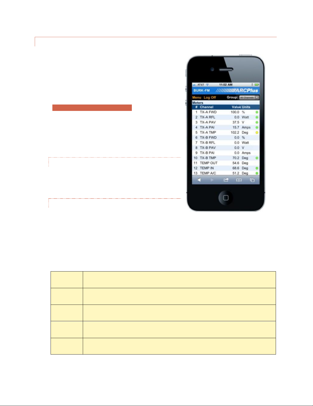
SMARTPHONE WEB PAGE
The ARC Plus smartphone-optimized web page is designed to work
with iPhone, Droid and other popular smartphones.
To access the smartphone interface, add /mobile/ to the URL for
your ARC Plus. For example, if your ARC Plus’ IP address is
192.168.0.100, navigate to:
http://192.168.0.100/mobile/
Be sure to include the trailing “/”.
The smartphone interface is designed for use on a smartphone or
other small format mobile device. While it is possible to view this
page on a desktop, laptop or tablet, the page may not display as
expected. However, the standard web interface will work correctly
on these devices.
SECURITY
The smartphone interface never transmits your password
unencrypted. When you log on, client-side code creates a oneway hash of your password to send to the ARC Plus.
NAVIGATING
When you log on to the smartphone interface you will see the
Channels page. This page displays your meter, status and
command channels in a vertical list. If you have more
channels than fit on one screen, scroll down to see more channels.
As with the web interface, use the Group list to select a channel bank.
Use the Menu link to display the additional features available in the smartphone interface:
Channels
Displays meter, status and command channels. This is the starting page.
Macros
Displays the macros on this ARC Plus and their current status. Allows you to run/stop macros.
Alarms
Displays all alarms on this ARC Plus. Alarms are displayed in a vertical list, with each field on its own line.
Events
Displays the event list.
Log Off
Logs off of the smartphone interface.
Smartphone web page on the iPhone

28
RECORDABLE SPEECH I NTERFACE
If your ARC Plus Touch is equipped with the optional RSI Recordable Speech Interface, you can take advantage of
the dial-in and dial-out capabilities to monitor and control your site from any phone. If you are familiar with the
earlier ESI Plus speech unit, you will find the RSI operates using the same familiar commands. Physically, the data
access arrangement (DAA) and transient protection are located on a separate field replaceable card. There are
several enhancements, but the most noticeable is the ability to add custom vocabulary to the standard broadcast
specific list. This is covered in the CUSTOM RECORDING section.
CONFIGURING THE RSI
Before you can use the RSI for monitoring and control, some configuration steps are necessary. You must
specifically assign ARC Plus sites, configure the site, channel and unit speech labels and configure greeting and
goodbye messages. For alarm notification you will also need to set up the selective dial-out lists.
There are also default settings that you may adjust, such as number of rings before the ESI answers an incoming
call, the amount of time the RSI waits between phone numbers on the dial out list, etc. All of these may be edited
via AutoLoad Plus and are described fully in RSI SETTINGS.
CALLING THE RSI
Calling in to the RSI allows you to monitor and control any remote site linked to the called site. To place a call to
the RSI:
1. Dial the phone number for the line connected to RSI. After the specified number of rings, the RSI will pick
up the line and speak the programmed greeting.
The RSI speaks ‘Hello” even if no greeting has been entered.
2. Enter your assigned PIN, followed by the # key. If you make a mistake, press * to clear the entry and start
over. If you enter an incorrect PIN, the RSI will speak, “Error,” and you can try again. Once you begin
entering the PIN, you have 20 seconds to
finish before the RSI disconnects. The
durations allowed to begin entering the
PIN and to complete entry are configurable
in AutoLoad Plus.
PINs are assigned in AutoLoad Plus under RSI SETT ING S.
3. Once you enter your PIN, the RSI will speak the user-programmed welcome message, followed by the
name of the site in which the RSI is installed and the number of alarms present at that site. After you log
in, the RSI waits for a user command. For a list of commands, Click or turn to RSI COMMAND LIST.
If PINs have not been assigned, use “0000#”.

29
RECEIVING DIAL-OUT ALARM NOTIFICATIO NS
In order for the RSI to dial out and report alarm notifications, dial-out must be enabled and the site and channel
must not be muted. Configure these parameters using the AutoLoad Plus software or the front panel configuration
menu.
The RSI executes the dial-out process as follows:
1
A non-muted channel enters an alarm state, and any specified alarm delay duration expires.
2
The RSI dials the first telephone number on the master dial-out list and allows a specified duration for the
line to ring, a user to pick up, and a password to be entered. The amount of time allowed to log in can be
modified using the AutoLoad Plus software.
3
If no user has supplied a password at the end of the time allowance, the RSI disconnects and remains idle
for a user-specified amount of time so that the line is free for incoming calls. The pause duration can be
modified in AutoLoad Plus.
4
After pausing, the RSI attempts the next phone number in the master dial-out list. Once all of the phone
numbers have been attempted, and if the alarm remains active, the RSI then attempts each number on the
alarm channel’s selective dial-out list, again pausing after each attempt.
5
If the alarm remains active after the selective dial-out list is exhausted, the RSI restarts from the master
dial-out list and continues the process until the alarm is cleared.
6
Once a user answers a call and enters a password, the RSI announces the name of the site where the alarm
is located, the number of alarms at that site, and the alarm conditions that prompted the dial-out
notifications.
7
The dial-out process ends when a user logs in and clears the alarm. If a user disconnects without clearing
the alarm, dial-out will continue.
SITE SELECTION
In a multi-site system, the RSI can facilitate dial-in access and dial-out alarm
notification for an unlimited number of interconnected ARC Plus sites. The site
presently reporting conditions, and the site where commands will take effect, is
considered the selected site. When you begin an RSI session, a site is already
selected by default:
When you dial in, the selected site is the
site where the RSI is physically installed.
When the RSI dials out, the selected site
is the site where the alarm occurred.
In both cases, the RSI will speak the name of the selected site immediately after log-in.
You can always find out
which site is currently
selected by dialing 400.

30
To change the selected site using preset numbers:
Enter 401-498 to select a site preset (presets are configured in AutoLoad Plus).
The RSI will speak the name of the selected site and report the number of alarms at
the site.
If you do not know the preset number of a site, or if the site is not stored as a preset:
Enter 499. The RSI will prompt you to use the telephone keypad to enter the first four
letters of the site name. Use the site name assigned to the ARC Plus unit and displayed
on the front panel, even if the site has a different name when spoken by the RSI.
If there is one site match, the RSI will announce the name of the selected site and
report the number of alarms at the site. If there is more than one match, the RSI will
prompt you to choose the site from a list of matches.
You may then enter any RSI command.
CHANNEL SELECTION A ND INPUT READING S
Once the desired site is selected, you can choose a channel for readings and commands by entering the channel
number (1-256). The RSI speaks the channel number followed by a report of that channel’s status input, as follows:
Status Input Condition
Spoken Report
Status input is not configured
No report
Status input is ON
Previously configured ON phrase*
Status input is OFF
Previously configured OFF phrase*
Status input is OFFLINE (has not yet been assigned a
value or is associated with a Plus-X device which is not
responding)
“STATUS OFFLINE”
*See section STATUS SPEECH LABELS to configure ON and OFF phrases.
The RSI then speaks the name of the metering channel, the current value, and the unit label. See section ME TE R
SPEECH LA B E LS to configure these phrases.
To repeat a channel reading at any time, dial 000.
Shortcut: When entering channels 1-99, you can speed up the selection process by entering 001-099.
ISSUING COMMANDS
After selecting the desired channel, you can issue a raise or lower command to that channel by pressing # for raise
or * for lower. The RSI will confirm your entry by saying, “raise,” or, “lower.” If the selected channel is not currently
configured, “not available” will be spoken. If the command channel is offline (is associated with a Plus-X device
which is not responding) “command offline” will be reported. You can then issue another raise or lower command,
or enter any other RSI command. For an updated metering reading at any time, enter 000.

31
REVIEWING STATUS CON DITIONS
To hear a report of all status channels at the site with a status ON, enter 350. The RSI will speak all Status On
messages. If a configured status channel is offline (has not yet been assigned a value, or is associated with a Plus-X
device which is not responding) “status offline” will be reported. The RSI will announce the end of the report when
you have heard the last status message. You can interrupt and exit a status report at any time with a new RSI
command, including 000 to repeat the selected channel’s meter reading. Entering 350 again will start a new status
report.
REVIEWING ALARMS
When the RSI dials out to report an alarm, it will speak the name of the alarm that prompted dial-out as soon as
you log in. At any time, you can access a list of all alarms at the site by entering 300. The RSI will report the number
of alarms at the site, and then read the first alarm in the list. The RSI waits for your input after each alarm. You
have the following choices:
#
Clear the alarm and go on to the next one.
*
Leave the alarm active (not cleared) and go on to the next one.
# # #
Clear all alarms at the site. The RSI will prompt you to confirm before clearing all alarms.
You can temporarily suspend alarm notification on any active alarm by pressing * followed by the desired number
of hours (1-9). For example, press “*4” to put alarm notification on hold for four hours. After four hours, if the
alarm is still active, the RSI will begin dialing out for this alarm once again. This method allows operators to ignore
an alarm for a period of time without clearing it.
The RSI will tell you when it has reached the end of the alarm report. You can then enter any command.
RUNNING MACROS
You can use the RSI to run or stop macros that are saved to the ARC Plus unit. To run or stop macros:
Each time the RSI speaks the running or stopped status of the macro, the status is valid only at the time the RSI
executes its query. A macro that is running one moment may execute its last line of code in the next moment, and
the RSI will not automatically announce a change of status. Entering a new run or stop command, reselecting the
1
Log in to the RSI.
2
Select the desired site by entering the site preset (401-498) or by spelling the site name
(499).
3
Once the desired site is selected, choose a macro by entering a macro preset number
601-698. Macro presets are set up using AutoLoad Plus software. If you wish to select a
macro from a menu, dial 699.
4
The RSI announces the name of the macro you selected, and whether the macro is
running or stopped.
5
To run the macro, press #. To stop the macro, press *. The RSI will confirm your selection
and read the macro status after it runs or stops the macro.
6
When you are done with macros, dial 000 to exit and repeat the current metering
channel reading.

32
macro preset number (601-698) or choosing the macro from the menu (699) will generate a new macro status
update.
If a macro executes for a very brief duration, it is possible to issue a run command only to hear the RSI announce
the new status as “stopped.” This may happen when the macro completes its last line of code before the RSI
queries the new macro status.
Besides running and stopping macros, you can listen to a list of currently running macros by entering 600. The RSI
will read the names of macros that are stored on the selected unit and running at the moment you enter your
query. Macros that stop during the macro report will be reported as running.
AUDIO INPUT MONITORI NG
Line level audio applied to the rear panel RCA jack labelled
AUDIO IN may be monitored over the phone. This is commonly
used for monitoring program audio or room noise.
You may begin monitoring by following these steps:
1. Log in to the RSI.
2. Dial 994 to begin monitoring the audio input.
3. Dial 995 to turn the audio off.
TIP:
To monitor multiple stations or points in
the audio chain, use an audio switcher
controlled by the ARC Plus.
Warning:
You may be able to issue commands while the audio
is playing, however, depending on the signal level, it
is possible for the audio input to overpower DTMF.

33
EDITING MASTER PHONE NUMBERS
There are two types of RSI dial-out lists: the master dial-out list, and the
selective alarm dial-out lists. Both are set up in the AutoLoad Plus software,
and the master dial-out list can be edited during an RSI session by a user with
system-level privileges. The master dial-out list allows users to receive
notification of all alarms prior to any other phone numbers being dialed.
Because the master phone number list can be edited via an RSI session, it
provides a convenient way for a user to add a temporary phone number to
the dial-out list. For example, if an operator will be away from their phone or
does not have access to their pager, they can call in to the RSI, add their
alternate phone number to the master dial-out list, and the RSI will dial that
phone number any time an alarm is received (dial-out must be enabled).
The master dial-out list also makes it possible for users to skip setting up selective dial-out lists if all operators wish
to be notified of all alarms in the system.
To edit the master dial-out list during an RSI session:
1
Log in to the RSI with system-level privileges.
2
Enter 801-809 to select a master dial-out entry 1 to 9. The RSI will respond by speaking
the phone number stored in that entry.
3
Press # to edit the phone number. The RSI will prompt you to enter the new phone
number. Use digits 0-9 only. If you make a mistake, press # and the ESI will revert to the
previously saved phone number. Press * when you are done entering the new phone
number. To delete an entry, press # followed by *.
4
The RSI will announce the new phone number entry.
5
Enter a new RSI command, or 999 to disconnect.
Note:
The master dial-out list does
not support the * or #
characters, or pauses in the
dialing string. For these
functions, set up one or more
selective dial-out lists using the
AutoLoad Plus software, and
link the list to the desired
alarm conditions.

34
MUTING ALARMS
In order for the RSI to dial out when an alarm occurs, the channel presenting the alarm must not be muted. If the
channel is muted, the ARC Plus will not record alarms at all, and the RSI will not dial-out when conditions are out of
tolerance. Alarm monitoring may be enabled/disabled using the front panel configuration menu, AutoLoad Plus
software, or during an ESI session, as described below. You can toggle alarm monitoring for all channels at a site, or
for specific metering and status channels.
To enable or disable alarm monitoring for all channels at a site:
1
Log in to the RSI with system-level privileges.
2
Dial 500. The RSI will report whether alarm monitoring is
enabled or disabled for the current site.
3
Press # to enable alarm monitoring, or * to disable it. The RSI
will report the new alarm monitoring condition.
4
You may then enter any RSI command.
To enable or disable alarm monitoring for a single status channel:
1
Log in to the RSI with system-level privileges.
2
Enter the channel number for the desired status channel. The
RSI will read the meter value and label for the channel.
However, the status channel with the same channel number is
still selected.
3
Dial 510. The RSI will report whether alarm monitoring is
enabled or disabled for the status channel.
4
Press # to enable alarm monitoring, or * to disable it. The RSI
will report the new alarm monitoring condition.
5
You may then enter any RSI command.
To enable or disable alarm monitoring for a single metering channel:
1
Log in to the RSI with system-level privileges.
2
Enter the channel number for the desired metering channel.
The RSI will read the meter value and label for the channel.
3
Dial 520. The RSI will report whether alarm monitoring is
enabled or disabled for the metering channel.
4
Press # to enable alarm monitoring, or * to disable it. The RSI
will report the new alarm monitoring condition.
5
You may then enter any RSI command.

35
ONBOARD HELP
Built-in voice guidance on the RSI operates in either of two modes, terse or verbose. Verbose mode is designed to
help novice users navigate the various functions. The RSI confirms each command, speaks a context-sensitive help
prompt after each command, and prompts the user for a new command after a period of inactivity. Terse mode is
for advanced users who need minimal prompting. The RSI will confirm each command, and will only prompt for a
new command just prior to disconnecting.
The RSI operates in verbose mode by default. To switch to terse mode, dial 997. The RSI will remain in terse mode
for this and subsequent sessions, until a user dials 996 to switch back. In addition to the context-sensitive prompts
in verbose mode, any user can summon a complete list of available commands by entering 998. The RSI will read a
list of commands. You can interrupt the list with a new command at any time. The RSI will finish reading the
current phrase before executing the new command.
COMMAND TIMEOUTS
When the RSI expects input from the user, it will wait for a user-specified amount of time before disconnecting.
The default duration is 60 seconds. If you need more time to enter a command, enter 993. The amount of the time
extension is configurable using the AutoLoad Plus software.
DISCONNECTING
When you are done using the RSI, enter 999. This makes the line immediately available for new calls. If you hang
up without disconnecting, it may take 60 seconds or more for the RSI to release the phone line on its own,
depending on the duration of the command timeout setting.

36
RSI COMMAND LIST
Login
Once the RSI starts speaking, enter the system or user PIN then press #.
Channel
Selection
1-256
#
*
Select Channel
Raise
Lower
Alarm Report
300
#
# # #
*
*1 - *9
Begin alarm report
Clear last alarm spoken
Clear all alarms on this site
Advance to next alarm without clearing
Mute current alarm for 1-9 hours
Status Report
350
*
Begin status report
Advance to next status message
Site Selection
400
401-498
499
Report currently selected site
Select site by preset
Select site by spelling site name
Alarm
Monitoring
500
510
520
#
*
Report alarm monitoring for selected site
Report status alarm monitoring for selected channel
Report metering alarm monitoring for selected channel
Enable alarm monitoring (after selecting 500,510 or 520)
Disable alarm monitoring (after selecting 500, 510 or 520)
Macros
600
601-698
699
#
*
Report currently running macros
Select macro by preset number
Select macro by using voice menu
Run selected macro
Stop selected macro
Master Phone
Numbers
801-809
#
*
Report the programmed phone number
Enter new phone number
Save entry
Special
Functions
993
994
995
996
997
998
999
Extend command entry timeout
Enable audio input monitoring
Disable audio input monitoring
Verbose mode (extensive guidance)
Terse mode (limited guidance)
Summon help prompt
Disconnect
INSTALLATION

37
A successful installation depends on preparation and proper sequence. (Sunday at 2AM is not the best time to be
looking for a manual or a needed tool.) Experienced engineers usually perform a complete setup at the bench
then install the equipment at the transmitter site, connect I/O and calibrate.od
NE EDED ITEMS
ARC Plus Touch Remote Control Unit
At least one Plus-X I/O device
A windows computer with access to the LAN for AutoLoad
AutoLoad software downloaded from www.burk.com
An Ethernet switch or sufficient ports on an existing LAN
Manuals for ARC Plus Touch and all peripherals, either printed or, preferably,
on a laptop or tablet that will be available during installation
A list of IP addresses and related information for your Ethernet connections to
the ARC Plus Touch and peripherals
RECOMMENDED S EQ UE NCE
The following sequence assumes the unit is unpacked and powered up at the bench. First, read the Introduction
section of this manual. As you read descriptions in the manual, it will be useful to follow along on the actual unit.
#
Step
Reference or Hyperlink
1
Perform the network setup using the touch screen
NETWORKS
2
3
4
5
6
7
8
9
10
Perform network setup on peripherals using a web
browser
Install AutoLoad software on a windows PC
Connect AutoLoad to the ARC Plus Touch
Assign Plus-X channels to ARC Plus Touch channels
Connect at least one channel to an appropriate voltage
Configure meter/status/command channels in
AutoLoad
Calibrate channels to read correctly
After full checkout, install at remote site
Connect all peripherals to Plus-X devices
Plus-X manual
USING AUTOLOAD PLUS SOFTWARE
CONNECTING TO THE ARC PLUS TOUCH
CONNECTING PLUS-X I/O UNITS
Plus-X Manual
METER CHANNELS
STATUS CHANNELS
COMMANDS
CALIBRATION
Plus-X Manual

38
REAR PANEL CONNECTI ONS
For most installations only the Ethernet connection and power connections are necessary. After completing the
initial checkout, you may wish to make additional connections for an external alarm, failsafe, an RS-232 connection
or the optional telephone interface.
Install the ARC Plus Touch in a location with access to your LAN/WAN. If you intend to operate the ARC Plus Touch
in a stand-alone configuration (dial-up modem and telephone access, but no TCP/IP connection), a network
connection must still be available for initial configuration. A crossover cable may also be used to connect a
computer directly to the ARC Plus Touch for configuration.
CONNECTING TO THE ETHERNET
Connect the ARC Plus Touch port marked ETHERNET to your LAN/WAN using CAT5e cable.
INIT IAL FRONT PANEL SETTINGS
Most of the configuration of the ARC Plus Touch will be done in the AutoLoad software program which may be
downloaded from www.burk.com/downloads. You will first need to use the front panel configuration pages to give
the ARC Plus Touch an IP address and set the time.
NE TWORK SETTINGS
Click or turn to NETWOR K for help editing the network information.
Enter the PRIVATE IP ADDRESS, PUBLIC IP ADDRESS and PORT values that will identify the ARC Plus Touch as a
unique device on the network. The private IP is the address you will use to access the ARC Plus Touch on your
company LAN/WAN. The public IP is the address this ARC Plus Touch will use to communicate to another ARC Plus
that is attached to an outside network. If this ARC Plus Touch will not be communicating with another ARC Plus on
a separate network, then enter the same address that you used for the private IP Address.
To access the ARC Plus from outside the company LAN/WAN with AutoLoad Plus or AutoPilot, you must port
forward the data port (TCP and UDP) to the private IP. To access the ARC Plus Touch web page from outside the
local network, you must port forward the HTTP port (TCP) to the private IP.
Additional network settings are available in AutoLoad Plus, but the ARC Plus Touch must first be made accessible
by setting the initial IP address from the front panel.
TIME SETTINGS
Click or turn to CLOCK for help editing the date, time, time zone and DST settings from the front panel. These
settings may also be made from AutoLoad Plus.

39
CONFIGURATION
USING AUTOLOAD PLUS SOFTWARE
To get started with configuration, you will need to download and install AutoLoad Plus software if you have not
done so already. The latest version of AutoLoad Plus is available at www.burk.com. The program provides access
to every system parameter such as metering, status, and command channel settings, calibration, user security,
front-panel display options, time and date settings, alarm notifications, RSI settings, macros, and more.
Note: Only System level users can access AutoLoad Plus.
CONNECTING TO THE AR C PLUS TOUCH
To modify ARC Plus Touch settings using AutoLoad Plus, start by launching AutoLoad Plus. AutoLoad Plus will
prompt for connection settings. Enter the IP address and your user name and password for the ARC Plus Touch site
you are connecting to. Then click Connect. (The default user name is admin, and the default password is
password.)
The Connect dialog automatically appears on startup.
Note: Select the Low speed connection option to optimize the AutoLoad Plus connection if you are not connecting
over broadband.
Once connected, AutoLoad shows the site you connected to on the left hand side of the window, along with any
other sites in the ARC Plus’ network. Click on a site to access its settings.

40
SAVING AND ARCHIVING ARC PLUS TOUCH CONFIGURATIONS
SAVING CONFIGURATIO N CHANGES TO THE ARC PLUS TOUCH
Any changes you make must be saved to the ARC Plus Touch before they become active. After making a
configuration edit, click the save icon in the toolbar or go to the File menu and choose Save. If you make unsaved
configuration changes in AutoLoad Plus and wish to undo them, go to the File menu and choose Revert. You must
revert any changes before saving them to the ARC Plus Touch.
ARCHIVING ARC PLU S TOUCH SETTINGS TO THE PC
To save a copy of the ARC Plus Touch configuration to your PC, select Save to File... from the File menu. Give the
configuration a file name and press Save.
UPLOADING ARCHIVED SET TINGS
To upload archived settings to an ARC Plus Touch, connect to the desired ARC Plus Touch site and click the Open
from File... toolbar icon. Select the desired file, click Open, and the settings will populate in AutoLoad Plus. Press
the Save toolbar icon to save the configuration to the ARC Plus Touch.
UPLOADING FIRMWARE
Programs > Burk Technology > AutoLoad Plus
1
Enter the IP address and port (normally 2000) of the
ARC Plus Touch.
2
Enter the username and password for any System level user.
3
Use the browse button (…) next to the firmware file to select
the firmware file you want to load.
4
Click Upload to upload firmware. The ARC Plus Touch will
reboot at the end of the process.
Important!
Uploading firmware
causes any latching
relays to release when
the ARC Plus Touch
unit restarts. The relay
state will be restored
after the process is
complete
41
CONNECTING PLUS-X I/O UNITS
First, configure the Plus-X device for your network following
the instructions in the specific Plus-X unit manual. Connect the
device to the same LAN as the ARC Plus Touch.
Make sure AutoLoad Plus is connected to the ARC Plus Touch.
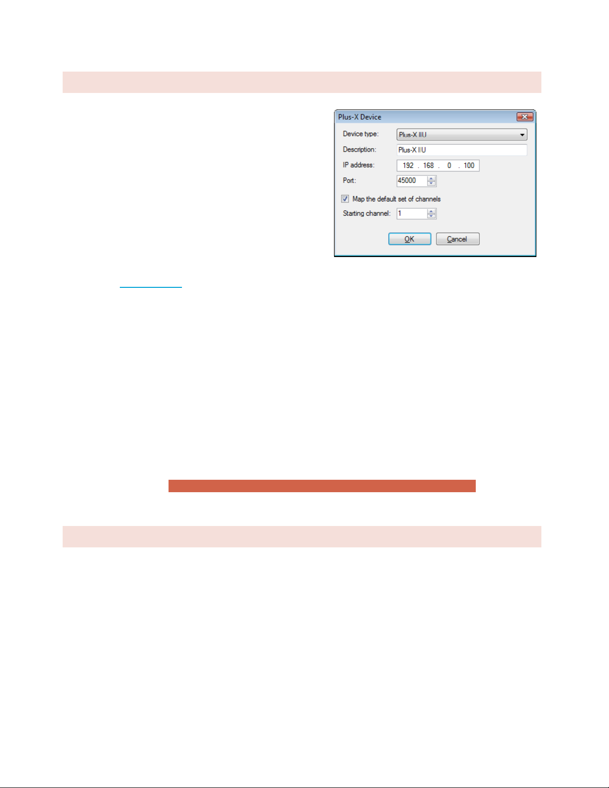
From the Edit menu, select Plus-X Devices. Click the Add…
button in the Plus-X Devices toolbar. Using the Device type
dropdown list, select the Plus-X device model type you are
adding, and enter the IP address you assigned it earlier.
If your Plus-X device model does not appear in the dropdown
list, you may need to download and install its XML definition
file. Plus-X XML definition files and installation instructions are
available at www.burk.com.
Once you have added the Plus-X device to the ARC Plus, Plus-X device channels must be assigned to channels on
the ARC Plus. Plus-X channels may be assigned manually or automatically. Automatic assignment is recommended
in most cases. Select the channel number where you want to start assigning channels. For your first Plus-X device,
starting at channel 1 is typical. Leave the “Map the default set of channels” checkbox checked and press OK.
If installing additional Plus-X devices, assign them to start after the last used channel. For example, if you are
installing two 16-channel Plus-X devices, have the first device start at channel 1 and the second device start at
channel 17.
For information on manually assigning channels, Click or turn to METER CHANN EL SOURCE .
After installing your Plus-X devices, click OK to close the Plus-X Devices dialog. You will see your new channels in
the AutoLoad Plus channel tabs for your ARC Plus.
Note: Be sure to save your AutoLoad Plus settings after assigning Plus-X channels.
CHANGING THE SITE NA ME
To change the name of the ARC Plus Touch site, highlight the ARC Plus icon in the site list, right click and select
Rename. Rename the site as desired (up to 12 characters).
Edit>Plus-X Devices - Add

42
MANAGING USERS
Edit > Settings > Users
The ARC Plus Touch manages users and privileges for up to 128 users, with up to 10 simultaneous connections via
any combination of AutoLoad Plus, AutoPilot, or web page. The same set of usernames and passwords is used for
each application. Usernames may contain up to 32 characters.
Note: Passwords are case sensitive; usernames are not.
Administrators can manage users and privileges by selecting Users from the Edit > Settings menu.
To add a new user, click the Add button. You will be prompted to assign the new user a name and password. Once
the new user appears on the user list, assign privileges by selecting an option from the Level column:
System
Full access to the ARC Plus Touch system. This level is
required to make configuration changes using AutoLoad Plus.
Operators
Can issue commands, run and stop macros, clear alarms, and
calibrate channels.
Observers
Read-only access.
You can rename an existing user by simply editing the Username field. To change the password, select the user
and click the Set Password… button in the toolbar. Use the Delete button to remove a user entirely.
Note:
While it is possible to
rename the default admin
user, you cannot delete this
user or change its access
level. Changing the
password for the admin user
is strongly recommended.

43
TIME SETTINGS
Edit>Settings>Time Settings
To change the date and time settings for the ARC Plus Touch, choose Time Settings from the Edit > Settings menu.
This opens the Time Settings dialog.
The General tab allows you to adjust the date display format, time zone, and the abbreviations used for the time
zone. If the ARC Plus Touch location observes Daylight Saving Time, check the box for DST.
To synchronize the time with your local PC, press the Synchronize button. AutoLoad Plus will set the ARC Plus
Touch site to the time shown on your Windows clock, adjusting for any time zone difference.
To configure the ARC Plus Touch to synchronize with an SNTP time server, use the SNTP tab. Enter the time server
IP address, port, and rate (in minutes) at which the ARC Plus Touch should synchronize.
Note: Using an SNTP server is recommended to ensure accurate timestamps and
scheduled operations.
The Advanced tab allows you to change the rules for Daylight Saving Time. The ARC Plus Touch uses United States
rules for DST by default. Changing these rules is only necessary for locations that follow different rules.
General time
settings are also
available on the
screen of the
ARC Plus Touch.

44
NE TWORK SETTINGS
Edit>Settings>Network Settings
To change the IP address and other network settings for the ARC Plus Touch, choose Network Settings from the
Edit > Settings menu. This will open the Network Settings dialog. Normally, the Public IP Address will be the same
as private. If another ARC Plus will connect from a different subnet, you will need to enter the WAN address for
this subnet and make sure the appropriate ports are forwarded.
The port default settings are; ARC Plus data port: 2000, PlusX port: 450000, SNMP port: 161 and HTTP port: 80.
If you are unsure of the settings to use, contact your
network administrator.
Note: In order to reference a mail server by host name
instead of IP address, a DNS Server is required.
If your firewall is configured to block access to port 80, the
HTTP Port setting can be used to change the port on which the embedded web server communicates.
If, for security reasons, you wish to turn off the embedded web server, uncheck the box marked Enable web
server. You will not be able to log in to the web page if this box is checked.
Tip: If you don’t know the DNS, Gateway and Subnet mask values, you may copy them from any computer that is on the same
subnet.
Important!
After clicking the OK button in the
Network Settings dialog, AutoLoad will
immediately commit your changes and
reconnect to the ARC Plus Touch.
Network settings are also
available on the screen of
the ARC Plus Touch.

45
SNM P SETTINGS
The optional SNMP Plus module can be installed in ARC Plus Touch units with firmware version 5.0.2.9 or higher.
SNMP Plus is a fully functional SNMP manager inside the ARC Plus Touch. It provides the ability to control and
monitor any SNMP device on the LAN or WAN without the need for parallel sensor wiring. In addition, with or
without installation of SNMP Plus, the ARC Plus Touch can send Traps (SNMP alarm messages) to up to four
external SNMP Managers. In sending traps, ARC Plus is performing one of the functions of an SNMP Agent. The
SNMP Manager and Agent capabilities in the ARC Plus Touch operate independently of each other, enabling the
unit to act as a Manager or an Agent or both at the same time.
ARC PLUS TOUCH AS A N SNMP MANAGER
This section describes settings that govern the ARC Plus when it acts as an SNMP manager, controlling SNMP
enabled devices at the transmitter site or other locations. SNMP Plus must be enabled on each ARC Plus Touch unit
by entering an authorization code in the AUTOPILOT AND SNMP PLUS AUTHORIZATION CODES tab in the
site settings dialog box.
Acting as an SNMP manager, the ARC Plus Touch can monitor and control any IP-connected device that has SNMP
agent capabilities. SNMP features were originally found only in networking devices like routers, switches, printers,
etc. Now a wide range of SNMP-enabled devices are available, including broadcast industry equipment like
transmitters, UPS systems, AC generators, RDS generators, mod monitors, satellite IRDs, audio processors, stereo
generators, codecs, STLs and more.
Configuration of the SNMP manger capabilities is done using AutoLoad Plus as described below.
ADDING SNMP DEVICES
The first step toward managing an SNMP device is to add it to the ARC Plus SNMP device list. To do this,
select SNMP devices… from the Edit menu. The SNMP Devices dialog box will be displayed as shown below.
From this screen, devices can be added to, edited or deleted from the ARC Plus SNMP device list.

46
Edit>SNMP Devices
The Name field determines how a particular device will be identified within the ARC Plus system, and can be
set to a convenient text string. The values for IP Address and (UDP) Port, as well as the Read and Write
community strings must agree with the corresponding settings in the SNMP device to be controlled.
From this screen it is also possible to Show OIDs. Highlighting a device on the list then selecting Show OIDs
will display a list of currently configured OIDs or Object Identifiers for the device, and the ARC Plus channel
assignments for those OIDs. An example OID list is shown below. Assignment of OIDs to ARC Plus channels is
discussed in subsequent sections.
Edit>SNMP Devices>Show OIDs
SNMP MIB BROWSER
Each SNMP managed device has one or more associated MIB (Management Information Base) files. MIB
files describe each parameter that can be retrieved from a managed device and each parameter that can be
configured on a managed device. AutoLoad Plus includes a MIB Browser that allows you to import MIB files
supplied by equipment manufacturers, and to browse through those files to identify desired MIB
parameters (OIDs) and assign them to ARC Plus channels. The AutoLoad Plus MIB Browser window is shown
below.

47
AutoLoad Plus SNMP OID Browser
IMPORT MIB FILES
The box in the lower right section of the window shows MIB files that are currently loaded into the instance
of AutoLoad Plus on your PC. The three files shown in the window above, RFC1155-SMI.mib, SNMPv1MIB.mib and SNMPv1-SMI.mib are standard MIB files that install automatically with AutoLoad Plus. Simple
network devices like printers may be completely defined by these standard MIBs. More complex devices
such as transmitters, codecs, power generators, etc. typically require vendor-specific MIB files. Often a
manufacturer will supply a directory or zip file containing several MIB files related to a particular piece of
equipment. To add these files to the AutoLoad Plus MIB Browser, click the Add button next to the MIB file
list. Then browse to and select one of the MIB files supplied by your equipment manufacturer. When you
select the file, AutoLoad Plus will import it into the MIB browser. You will see the file name added to the list
of Imported MIB files, and you will see the MIB tree in the left window expand to include the tree branches
defined by the newly imported MIB file.
In addition to importing the selected MIB, the Browser will import other associated MIB files that it finds in
the same directory as the selected file.

48
BROWSE TO A DESIRED MIB PARAMETER
Once the desired MIB files have been added to the MIB file list, the navigation box at the left side of the
screen can be used to locate specific MIB parameters or OIDs. The MIB structure can be expanded or
collapsed by clicking on the folder icons, similarly to a Windows file structure. By navigating through the
tree, a particular parameter can be identified to be either read from the target device or sent to the target
device. In the illustration above, the OID parameter “ifNumber” has been highlighted:
Information related to the highlighted parameter appears in the upper right section of the MIB Browser
window, including the OID that will uniquely identify this parameter to the SNMP-managed device. The
parameter name and a text description are also shown. In addition, the Access field tells whether the
selected MIB parameter is read-only or read-write. The Syntax field specifies the format for the data
associated with the MIB parameter. If your vendor-specific MIB includes tables, a Table key can be entered
in the box shown to specify the desired table item.
Once the desired MIB parameter has been highlighted, clicking “OK” will assign that parameter to an ARC
Plus meter, status or command channel.
DISPLAY THE CURRENT VALUE OF A MIB PARAMETER
The final function of the MIB Browser is to allow retrieval of a test value for the selected MIB parameter.
Clicking the “Get” button will cause an SNMP “Get” command to be sent to the device, requesting the
current value of the highlighted parameter. In the example shown above, the retrieved value for ifNumber
is “3”. This capability can be used to verify SNMP communication with the device and also to confirm the
data format of the selected parameter.
ASSIGNING SNMP PARAM ETERS TO METER, STATUS AND COMMAND CHANNELS
The MIB Browser is used by AutoLoad Plus when assigning a parameter from an SNMP device as a Source
for a meter channel, a status channel or a command channel. Descriptions of these three actions can be
found in the following sections of this manual:
METER CHANNEL SOURCE
STATUS CHANNEL SOURCE
COMMAND SOURCE
ARC PLUS TOUCH TRAP GENERATION
This section describes settings that control the ARC Plus when it sends SNMP traps. Trap generation is one function
of an SNMP Agent. The ARC Plus Touch can send trap messages to up to 4 different SNMP mangers. Based on user
configuration, the ARC Plus Touch will send either preconfigured or custom trap messages, or both. Configuration
of the SNMP trap capabilities is done using AutoLoad Plus as described in the following sections.

49
SETTING UP ARC PLUS TOUCH TO SEND TRAPS
To configure the ARC Plus to send SNMP Traps, select SNMP Agent Settings… from the Edit > Settings
menu. The following dialog box will be displayed>
Edit>Settings>SNMP Agent Settings
The SNMP community string is used by an SNMP manager as a means to authenticate the SNMP agent. If a
unique string is specified here for the ARC Plus, it must also be pre-configured in the SNMP manager(s) that
will be receiving traps from the ARC Plus. The community string can be set to any desired text string.
ARC Plus Touch can be configured to send traps to up to four different SNMP managers. The IP address and
UDP port for each manager must be entered in the fields shown above. The default port value of 162 is
often used for trap transmission.
No SNMP traps will be generated for an alarm condition on a muted channel. If a channel is set to mute
while an alarm condition is active, SNMP trap generation for that channel will stop. If a channel is taken out
of mute while an alarm condition is active, SNMP trap generation for that channel will begin.
SENDING PRECONFIGURED TRAPS
When the “Send traps on alarm” box is checked, the following four preconfigured ARC Plus Trap Messages
are enabled:
Trap OID
Trap meaning
1.3.6.1.4.1.26079.2000.1.0.1
This trap is sent at the start of an alarm.
1.3.6.1.4.1.26079.2000.1.0.2
This trap is sent when the underlying alarm condition returns to normal.
1.3.6.1.4.1.26079.2000.1.0.3
This trap is sent if the alarm condition is manually cleared.
1.3.6.1.4.1.26079.2000.1.0.4
This trap is sent whenever an event is placed in the event log.
The trap OID or Object Identifier tells the SNMP manager which specific message type has been received.
Along with the OID, each of these trap messages includes a data value formatted as an Octet String variable,
containing an ASCII string. For the first 3 traps listed above, the associated ASCII string is made up of 4 parts:

50
Part 1 is “Low Warning Alarm” or “Low Critical Alarm” or “High Warning Alarm” or “High Critical
Alarm”.
Part 2 is the value of the channel that is in alarm, for example “150”.
Part 3 is the units of the value, for example “kW”.
Part 4 is the label assigned to the channel, for example “Chan 1”.
So an example of a complete ASCII string might be “Low Critical Alarm 150kW Chan 1”. For the fourth trap
listed above, the associated ASCII string contains the same text that is placed in the event log. Preconfigured
ARC Plus Trap Messages are sent using the SNMP v2C message format.
SENDING CUSTOM TRAPS
When “Configure custom SNMP Traps (advanced)” is selected, the following screen is displayed.
Edit>Settings>SNMP Agent Settings>Configure custom SNMP Traps (advanced)
Using this screen, the user can specify up to 64 custom trap OIDs, each one to be triggered by the
occurrence of a user-selected alarm type on a user-specified meter channel or status channel. Custom Trap
Messages will be sent only if the “Enable custom traps” box is checked. Custom traps are sent using the
SNMP v1 message format.
The custom SNMP traps specified on this page can be sent repetitively during the time their associated
alarms are active. A value between 0 and 65535 must be entered to specify the desired repetition interval in
seconds. An entry of 0 turns the trap repetition feature off.
Each Trap is defined by a sequence of dot-separated numbers know as an OID (Object Identifier). This page
allows construction of an OID for each desired trap. The Enterprise number entered at the top of the screen
will become part of the Trap OID for each of the traps configured on the page. The Enterprise number is
typically 1 to 5 digits with no internal dot separators.

51
The trap OID field allows entry of an arbitrary OID “segment”. The number entered must be unique for each
specified trap. It must start with a digit and be followed by a set of dotted numbers with no concluding dot.
Each complete custom OID is made up of the OID Root followed by the Enterprise number and ending with
the number entered in the Trap OID field. This complete OID will be sent when the selected alarm type
occurs on the identified channel.

52
EMAIL AND DIAL-OU T NOTIFICATIONS
Each alarm can be linked to an email notification list and/or a dial-out list to alert personnel to out-oftolerance conditions or system alarms (such as an offline ICRU). In order for email alarm notifications to be
sent, the ARC Plus Touch must have access to an SMTP server. For dial-out notification, the optional RSI Plus
must be installed.
Configuring notifications is a two-step process: first, the notification lists must be created in the Alarm
Notifications window; then the alarm conditions must be configured to use the appropriate lists. This is
accomplished in the Status Notifications and Meter Notifications tabs of the channel configuration area,
after you have configured status and metering channels.
CONFIGURING EMAIL A LARM NOTIFICATIO NS
To set up email notification and dial-out notification lists, choose Alarm Notifications from the Edit > Settings
menu. This opens the Alarm Notifications dialog.
Edit>Settings>Alarm Notifications – Email Settings

53
EMAIL SETTINGS
Before setting up list members, enter the hostname or IP address of the mail server and the server port If
referencing the mail server by name, a DNS must be entered in the Network Settings configuration. Click or turn to
NETWORK SETTINGS.
Emails originating from the ARC Plus Touch must have a From address and a Reply address. Any undeliverable
notifications will be sent to the reply to address. Most administrators simply enter their own email address for
both of these settings.
If your server requires authentication, enter the User name and User password where prompted.
CONFIGURING THE EMAI L CLOUD SERVICE
The Burk Email Cloud Service is supported in ARC Plus Touch firmware version 5.0.2.1 and higher. The Cloud
Service works in conjunction with your ARC Plus Touch system to originate encrypted emails using the
STARTTLS protocol extension. If your current email server does not support STARTTLS, you can open a free
email account with an Internet email service provider. The Burk email cloud service is compatible with email
services from a wide range of providers including Gmail, mail.com, GMX and Zoho. It is suggested that you
create an email account dedicated for use with your ARC Plus systems. This will make it easier to identify
and sort email received from the ARC Plus systems, and to monitor email activity. To configure the ARC Plus
system for use with the cloud service, complete the following additional configuration steps:
Check the “Enable Cloud Emails” box.
Accept the default Cloud server, cloud.burk.com.
Accept the default Cloud port, 4095
Accept the default Cloud protocol, STARTTLS
Click “OK” to submit the dialog box.
Select File>Save to save the updated configuration to the ARC Plus Touch unit.
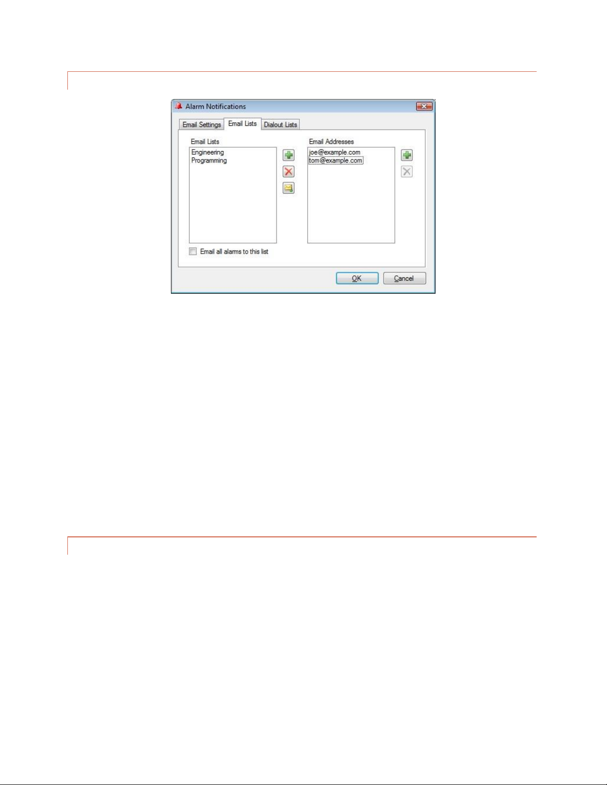
54
EMAIL LISTS
Edit>Settings>Alarm Notifications – Email Lists
Each status alarm and each metering alarm threshold can be linked to one of up to 32 email lists, allowing alarm
notifications to be directed to the appropriate personnel.
To create an email list, click the Email Lists tab. Click the Add button (plus sign icon) to the right of the Email Lists
column and enter the name of your first list where prompted. Then click the Add (plus sign) button to the right of
the Email Addresses column and add email addresses to the list until complete. When you are done, you can click
the Test Email button (envelope icon) to test your email settings. A test email will be sent to all addresses in the
selected list.
Now that you have created at least one email list, this list will be available for selection in the Meter Notifications
and Status Notifications tabs when you configure ARC Plus Touch channels.
CONFIGURING DIAL -O UT ALARM NOTIFICAT IO NS
If an RSI is installed in any ARC Plus Touch in the network, metering and status alarms can trigger dial-out
notifications to telephone numbers on your dial-out lists. Each status alarm and each metering threshold can be
linked to one of up to 32 dial-out lists, and each list can contain up to 12 telephone numbers.
The RSI allows administrators to program a master dial-out list, which will be called prior to any alarm-specific dialout lists. If you wish to use this master dial-out list in lieu of alarm-specific lists, you do not need to complete the
steps below. See EDITING MASTER PHONE NUMBERS for information on programming the master dial-out list.

55
DIAL-OUT LISTS
Edit>Settings>Alarm Notifications – Dial-out Lists
To set up your dial-out lists, navigate to the Dial-out Lists tab. Click the
Add button (plus sign icon) to the right of the Dial-out Lists column and
enter the name of your first list where prompted. Then click the Add
button (plus sign icon) to the right of the Phone Numbers column and
assign telephone numbers to this list.
If you wish for an alarm
notification to dial a
modem-equipped PC
running AutoPilot, precede
the telephone number with
D (for data). This is a useful
way to log an alarm to the
PC if there is no IP
connectivity to the remote
site.

56
SITE SETTINGS
Many system settings are user-definable, and can be configured by accessing the Site Settings dialog from the Edit
> Settings menu.
Edit>Settings>Site Settings
STARTUP BEHAVIOR
The Startup tab allows you to configure ARC Plus behavior on initial power up.
Check the Mute alarms box to suppress all alarm notifications for a specified duration after startup. This provides
an opportunity for equipment to recover from a power loss after startup without causing out of tolerance
conditions.
Check the Delay macros box to prevent any macros from running during the specified duration after startup. This
feature can be used to prevent macros from using readings from equipment that has not yet stabilized or sending
commands to equipment that has not yet come back online.

57
For older systems installed with legacy PlusBus ICRU units, the
Restore relay states box allows you to configure the behavior
of the ICRU relays upon recovery from a loss of power. Check
the Restore relay states box if you want the ARC Plus to return
all command relays to the state that was saved upon loss of
power. Leave the box unchecked if you want the relays to
remain open when power is restored.
TIMEOUT SETTINGS
Edit>Settings>Site Settings - Timeouts
After certain connection errors, AutoLoad Plus, AutoPilot and the ARC Plus will log events and/or display error
messages. The Web interface will log off after the specified inactivity period. Timeout durations are userconfigurable in the Timeouts tab.
Note: For Plus-X IIU and ICRU systems,
the relay state will be automatically
restored upon power recovery. Leaving
the Restore relay states box unchecked
will not disable this feature.

58
FRONT PANEL BEHAVIO R
Edit>Settings>Site Settings - Front Panel
The front panel behavior of the alarm LED, alarm list, and status report display is user configurable.
Under Front Panel Alarm LED, the LED indicates alarm on local site option causes the front panel LED to illuminate
when there is an alarm condition on any of the equipment physically connected to the unit. The LED indicates
alarm on any site option causes the LED to illuminate when any site in the ARC Plus network has an alarm.
If you want cleared alarms to appear in the front panel alarm list, check the box marked Show cleared alarms.
Cleared alarms appear beneath uncleared alarms and show the date and time they were cleared.
If you want the status report to show status off and status on messages for every channel, check the box marked
Show all status conditions. Otherwise, the front panel status report will only include status on messages.
The Front Panel Passcode feature, available in firmware version 5.0.1.1 or higher, adds enhanced security to your
ARC Plus. The passcode, entered in the field shown above, can consist of up to 8 numeric digits. After the passcode
has been set on the ARC Plus, the front panel interface will lock under the following conditions: 1) any time the
ARC Plus unit is powered on, or 2) if the user selects MENU>LOCK on the front panel, or 3) when the screen saver
delay is reached if the screen saver has been set to “Turn the display off”. (See SCREEN SAVER SETTINGS, below.)
When locked, the display will be dark. To unlock the display, touch the dark screen. This will cause the screen to
display a numeric keypad. Enter the passcode and touch UNLOCK.
The passcode can be changed or removed in the same way that it was set.

59
SCREEN SAVER SETTING S
Edit>Settings>Site Settings - Screen Saver
The color LCD screen may be configured to dim or turn off after the front panel controls have been inactive for a
specified duration. This feature is designed to prevent screen “burn-in” over the service life of the ARC Plus Touch.
If the ARC Plus Touch LCD is already in screen saver mode when you make a change to these settings, the screen
saver will not update until the next time the front panel enters screen saver mode.

60
ALARMS
Edit>Settings>Site Settings - Alarms
The behavior of the rear panel alarm relay may be configured to latch closed when there is an alarm at the local
site, or when there is an alarm at any site in the ARC Plus network. Under the Alarms tab, select your preference
under the Alarm Relay heading.
The System alarm dial-out list and System alarm email list determine which notification lists the ARC Plus will use
when there is a system alarm on the ARC Plus (such as Plus-X device becoming disconnected). To configure email
notifications of system alarms, email server settings and at least one email notification list must be configured
(Click or turn to CONFIGURING EM AIL ALARM NOTIFICATIONS). In order to select a dial-out list, an RSI must
be installed and there must be at least one dial-out notification list created (Click or turn to CONFIGURING DI AL-
OUT ALARM NOTIFICATIONS).
The Alarm on Lost Plus-X Device box is checked as a system default. Unchecking this box disables the system alarm
that normally occurs when communication is lost with a connected Plus-X device. It is highly recommended that
this box remain checked so that any network failure between the ARC Plus Touch and its connected Plus-X devices
can be quickly identified and corrected.

61
EVENTS
The ARC Plus has an onboard events list to record various types of activities as they take place on the system. You
can control what types of events are recorded by checking or unchecking the items in the list on the Events tab.
Edit> Settings>Site Settings - Events
PRIMARY/BACKUP R SI CONFIGURATION
Edit>Settings>Site Settings - ESI
When an alarm occurs, an ARC Plus Touch without an RSI installed can connect to an ARC Plus unit with an RSI or
ESI installed in order to provide dial out notification of the alarm condition. Because more than one RSI or ESI Plus
may be installed in a network of ARC Plus systems, the ESI tab allows you to configure primary and backup sites.
When an alarm occurs on the local ARC Plus Touch and dial-out notification is enabled for that alarm, the ARC Plus
Touch will initiate dial-out using the RSI installed at the site designated as Primary ESI site. The ESI site timeout
setting determines how long the ARC Plus Touch will wait for a response from the primary RSI or ESI Plus. The ESI
Note:
Depending on how you configure
your ARC Plus, some activities may
generate a high volume of events.
For example, running macros
frequently will generate many macro
events. Configure the ARC Plus
events accordingly to best suit your
needs.
Note:
AutoLoad Plus works with
older ARC Plus units as well
as ARC Plus Touch Version 5.
The program refers to the ESI
whenever an ESI Plus or an
RSI applies.

62
site max retries setting determines how many times it will retry the primary site before attempting to connect to
the Backup ESI site.
WEB INTERFACE
Edit>Settings>Site Settings – Web Interface
The Web Interface tab allows you to customize the web interface welcome message.
MODEM SETTINGS
Edit>Settings>Site Settings - Modem
If you are connecting a dial-up modem to the ARC Plus, enter the modem’s initialization string and connection
speed where prompted. The Inactivity timeout determines how long the ARC Plus will wait after the last data
exchange before disconnecting a modem connection.
To allow the modem to be used for dial-out notifications and incoming calls, leave the Dial-out on alarm and
Answer calls boxes checked. Disabling these options is a means to turn off the modem functionality for this site.

63
Checking “Serial port is RS232” enables communication to the ARC Plus via serial port without a dial-up modem.
AUTOPILOT AND SNMP PLUS AUTHORIZAT ION CODES
Edit>Settings>Site Settings - Authorization
When you purchase a license for AutoPilot or SNMP Plus, an authorization code is provided for one ARC Plus unit.
Enter the authorization code where prompted in order to begin using AutoPilot or SNMP Plus with this ARC Plus
Touch.
Note:
The ARC Plus will retain the
authorization codes after
upgrading firmware,
resetting factory settings or
cycling power. However,
keeping a record of your
authorization codes is
strongly recommended.

64
HIDING UNUSED CHANNE LS
The ARC Plus Touch front panel, AutoPilot and web page will
show all 256 metering, status and command channels (real or
virtual). If fewer channels are used, you can remove unused
channels from display by clicking the Hidden Channels tab and
checking off boxes under the Hide heading. This will remove
the metering, status and command channels from view.
If you have a block of channels to hide or
unhide, choose Hide/Unhide Channels…
from the Tools menu to select channels in
blocks.

65
CONFIGURING AN ARC P LUS NETWORK (M ULTI-SITE INSTALLATIONS)
When more than one ARC Plus unit is installed within an organization, grouping the units together in a single ARC
Plus network offers the advantage of site-to-site control, where commands and macros issued by one unit can
control equipment connected to another unit. It also allows alarms from one site to appear on the front panel of
any other site, and front panel LEDs can be mapped to conditions on any other site.
ADDING SITES TO THE NETWORK
Once your ARC Plus sites are connected to the LAN/WAN, grouping them is easy. Start by connecting to one site in
AutoLoad Plus. After the first site is connected, choose Add Site… from the Edit > Site List menu. You will be
prompted for the IP address, port, username and password of the site you are about to add. Click OK. AutoLoad
Plus will connect to the second site and the two sites will now be part of the same ARC Plus network.
CATEGORIZING SITES
Adding category names to a large ARC Plus network can make it easier to navigate between sites. To add a
category name, choose Add Base Category from the Edit > Site List menu and add as many root level categories as
desired. You can then create subcategories by choosing Add Category from the Edit > Site List menu.
SETTING THE NETWORK PASSWORD
Tools>Set Network Password
Each ARC Plus site has a network password that is used when connecting to other sites on the network. This
prevents unauthorized ARC Plus sites from connecting to your network. Units shipping from the factory have a
default network password of password. It is strongly recommended that you change this password by choosing Set
network password… from the Tools menu. AutoLoad Plus will change the network password for all units
connected. When adding a new unit to an existing network, the network password must be set on the new unit
before it can be added to the network.
The network password is also used as the basis for secure communication with the Warp EngineTM polling feature
in AutoPilot®. ARC Plus Touch units running firmware 5.0.3.4 or later are compatible with the AutoPilot Warp
Engine.
Important!
All ARC Plus units in the
network must have the
same network password.

66
Warp Engine polling is fast, enabling real-time monitoring of up to 100 sites per second, with each site reporting as
many as 32 status and/or meter values. Larger networks just take a little longer, for example polling up to 500 sites
in 5 seconds. Warp Engine polling is efficient in its use of communications bandwidth. It uses very small packets,
sending only required data and minimizing communications overhead. Polling 32 channels from 100 sites requires
only 37,800 bytes per second of IP capacity at the central site, and only 378 bytes per second at each remote site.
If communications bandwidth is at a premium cost, it can be further reduced by selection of a slower poling rate.
RSI SETTINGS
If an RSI is installed, telephone speech properties are configurable using the RSI Settings dialog, accessible by choosing Speech Settings
from the Edit > Settings menu.
GENERAL
Edit>Settings>ESI Settings - General
In order to enable dial out notifications, check the box marked Dial out on alarm. The RSI will dial out when there
is an alarm condition under the following circumstances:
The alarm condition is configured to dial out to a notification list.
The site with the alarm has designated this RSI as a primary or backup RSI.
The dial out on alarm box is checked.
If you want this RSI to answer incoming calls, check the box marked Answer incoming calls and specify the number
of rings the RSI should wait before picking up the line. After answering the call, the RSI speaks the configured
greeting and will continuously repeat the greeting to allow time for the user to enter a valid PIN. To increase the
amount of time for PIN entry, increase the number of times the greeting is repeated.
For compatibility with
older versions of the ARC
Plus, AutoLoad Plus
makes reference to ESI. In
all instances, the ESI
settings apply to the RSI.

67
When the RSI dials out with alarm notifications, the phone line will not allow inbound calls. Adding a delay
between dial-out attempts allows users the opportunity to dial in. Configure the duration of this delay in the
Wait ___ seconds before dialing… field.
Finally, enter System and Operator PINs that will be used for RSI login purposes. The system PIN provides full
access to the ARC Plus Touch system (including editing master phone numbers, disabling alarm reporting, and
muting channels), while the operator PIN allows readings, commands and macros. PINs may contain up to eight
digits.
RSI PHRASES
The ESI Phrases tab allows configuration of the phrases used to greet the caller, say goodbye, and accept or reject
passwords.
Edit>Settings>ESI Settings – Phrases
Greeting
Spoken as soon as the RSI Plus picks up the line.
The word “Hello” is always spoken prior to the
greeting.
Welcome Message
Spoken after the user enters a valid PIN.
Rejection Message
Spoken if an incorrect PIN is entered.
Goodbye Message
Spoken when the caller disconnects. The word
“Goodbye” is always spoken after the message.
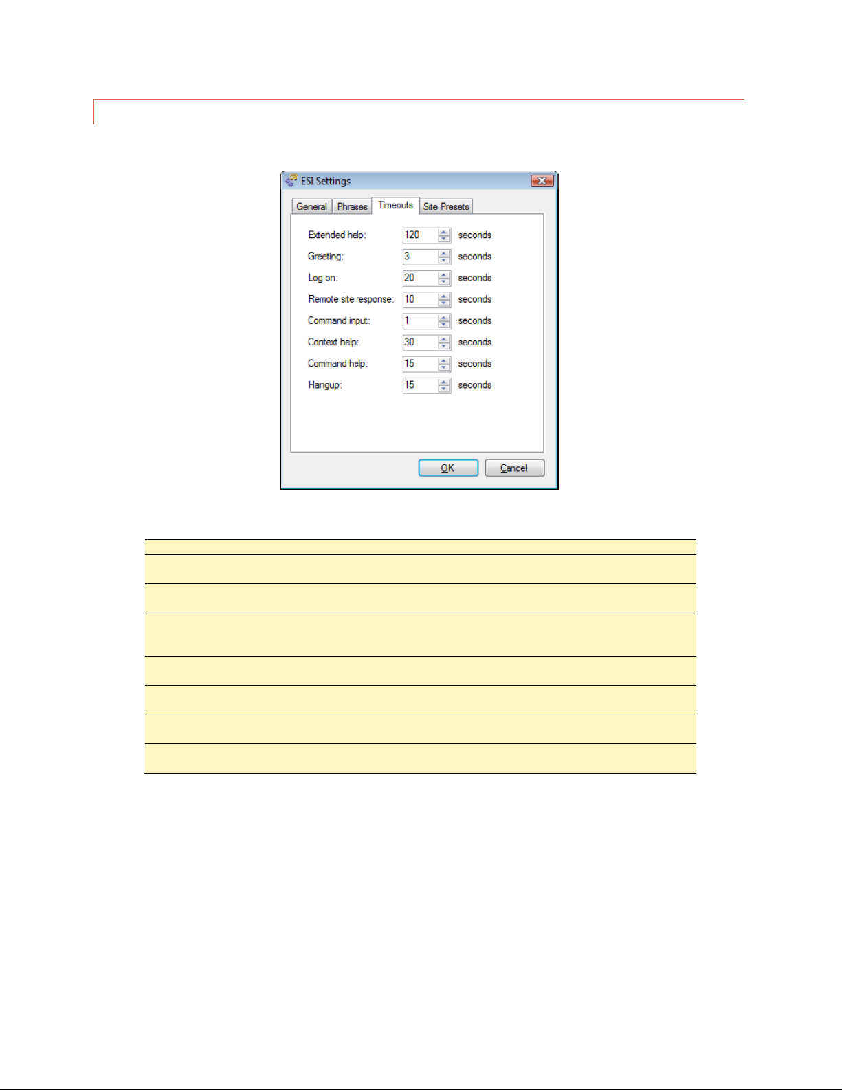
68
RSI TIMEOUTS
The Timeouts tab allows you to adjust default timeouts and timed responses from the RSI.
Edit>Settings>ESI Settings – Timeouts
Extended help
The amount of time the RSI waits before providing a context-sensitive help prompt.
Greeting
The amount of time the RSI pauses between repeated greetings during the login
process.
Login
The amount of time allowed to complete PIN entry. After the user begins entering a
PIN, the RSI allows the configured amount of time to complete entry.
Remote site response
The amount of time the RSI allows for another ARC Plus site to supply data that this
RSI requested. After this duration has elapsed, the RSI will speak, “Error” and you
may enter more commands or disconnect.
Command input
The amount of time the RSI allows after the last DTMF tone before accepting the
DTMF sequence as a single command.
Context help
The amount of time the RSI allows after a brief help prompt before speaking an
extended help prompt.
Command help
The amount of time the RSI allows after an extended help prompt before speaking a
list of available commands.
Hang-up
The amount of time the RSI allows after speaking the command list before hanging
up due to no activity.

69
SITE PRESETS
In multi-site systems, it may be easier to select new sites
using a preset list, in lieu of spelling the site name with the
telephone keypad. To set up presets for up to 98 remote
sites, click under the Site heading to choose a site name for
as many preset numbers as desired. Once presets are
established, entering 401-498 during an RSI session will
make the new site active for the session.
Edit>Settings>ESI Settings – Site Presets
MACRO PRESETS
To set up the preset numbers used to identify macros during an
RSI session, open the ESI Macro Presets dialog from Edit >
Settings > ESI Macro Presets… and select macro names to be
associated with as many presets as desired.
SITE SPEECH LABEL
To assign the ARC Plus a speech label for site identification during an RSI session, choose Set Site Name Speech
Labels… from the Tools menu. Even if an RSI is not installed on a particular ARC Plus unit, assigning a speech label
allows other RSI units to identify the unit during an RSI session.
Edit>Settings>ESI Macro Presets

70
CUSTOM RECORDING
The vocabulary shipped with the RSI is taken from the broadcast industry
vernacular, but of course doesn’t include words and phrases specific to your
site. By being able to use words you’ve recorded, the RSI adapts to your needs.
You’ll need a PC program to record the words and the means to output the
sound files as 16-bit 8 kHz mono wave files, each less than 8 seconds in
duration. Whatever your station uses for a DAW is fine, but if that is not
convenient, Audacity is free and works just fine.
VOCABULARY FILE SYST EM
The vocabulary is entirely resident on an SD card inside the ARC Plus Touch. You can record custom words and
phrases and upload these into your ARC Plus Touch without removing the SD card using the Speech editor in
AutoLoad Plus Touch.
The Speech editor in AutoLoad Plus will update the internal ARC Plus Touch speech files as needed. To prevent
problems, we strongly recommend only editing the speech system with this editor. (There may be a file named
Firmware.hex on the SD card. It can be safely removed if desired.)
RECORDING ADDITIONA L VOCABULARY
Use your DAW to record each word or phrase as desired. You must set the editor to produce 16-bit mono wave
files at an 8 kHz sample rate. Stereo or any other rate will result in an error. If you are using Audacity, you can set
the default sample rate and sample format by going to Edit> Preferences which opens the Preferences: dialog box.
Choose the Quality tab and set the defaults as shown.
Audacity Edit>Preferences - Quality
Edit the recording to produce separate wave files for each word or phrase. Trim the recordings to produce
consistent heads and tails with only a few tens of milliseconds of silence. Give each file a filename that represents
Not an announcer?
Let your production
department record your
custom vocabulary.

71
the recorded word or phrase. The file name will become the exact entry in the vocabulary list. Normalize the
recordings to full amplitude so that the recordings will match the standard vocabulary in level.
All files must be 8 seconds or less in length.
SAVING YOUR CUSTOM VOCABULARY
In AutoLoad Plus, connect to the desired site. In the left hand window, click on the site that has the RSI to be
updated and then select Tools>Speech Editor. The speech editor, when connected to a site, will display both
system phrases and any existing custom speech phrases.
You can limit the display of phrases by using the two buttons at the top and can further restrict the list using the
Search box.
To add a recorded phrase, press the Add button. The Select a mono, 16-bit, 8kHz WAV file to import dialog box will
open. Select the desired file and press the Open button. This will add the file to the vocabulary.
These instructions require
that your ARC Plus Touch
has firmware version
5.0.1.19 or newer and you
are using AutoLoad Plus
version 3.1.72 or newer.

72
After all the new custom files have been added, there are three Save options:
Save to Folder: This will save the vocabulary file system, including your newly added custom speech additions, as
three RSI files to your computer.
It is recommended to use this function to create a back-up copy of your speech files any time you make custom
additions. Additionally, once you have a copy of these files on your PC, you can use the speech editor off-line (not
connected to your ARC Plus Touch) and continue to add to or edit this copy of the vocabulary files, which can then
be uploaded into your unit when a connection is active.
Save to Unit: This saves your updated vocabulary file system directly onto the connected ARC Plus Touch.
Save to All Units: This saves your updated vocabulary file system directly to the connected ARC Plus Touch as well
as updating any additional ARC Plus Touch units that are networked to the connected site.
CustomData.dat
CustomIndex.dat
CustomSpeech.xml

73
METERS
Configuration for the ARC Plus metering channels is broken out into several tabs in the main display area of
AutoLoad Plus. Complete the configuration fields on each tab to set up your analog metering inputs.
METER CHANNELS
The Meter Channels tab permits entry of the channel label, units label, sample type, decimal place and source.
CHANNEL AND UNITS L ABELS
Under the Label and Units Label headings, enter names for the metering channel and the unit of measurement.
These labels appear on the front panel, web page, and in AutoPilot.

74
METER TYPE
Your selection for calibration type determines how the ARC Plus scales the raw input value:
Millivolt
Does not scale the raw input voltage; it
applies a calibration constant of 1. A 300mV
sample will be displayed as 300 on the ARC
Plus, and the channel cannot be manually
calibrated.
Linear
Multiplies the raw input voltage by a
calibration constant that is determined by
comparing the sample voltage to the value
entered during manual calibration. The Linear
(Absolute) input type displays the absolute
value of a linear input, and the Linear
(Negative) input type is used for values with a
negative voltage input; positive values are
clipped to 0.
Degree
Divides the raw input voltage by a 0.1 to
show temperature readings from the Burk
Technology BTU-4 temperature unit, which
provides a 10mV / degree output. The
decimal setting for channels configured for
degree is locked at 1 (000.0).
Indirect
Multiplies the raw input voltage by the scaled
value of the previous channel and multiples
the product by a calibration constant.
Power
Squares the raw input voltage and then
multiples the product by a calibration
constant.
VOLTAGE RANGE
The voltage range is always -10 to +10 on Plus-X inputs. No setting is required.
SAMPLE TYPE AND TIM E
The ARC Plus can optionally take an average, minimum or maximum of a meter channel. To select this behavior,
use the Sample Type column. Set the time (in seconds) in the Sample Time (sec) column. You must enter the time
in seconds, so use 600 for 10 minutes, 3600 for an hour, 86400 for a day and 2592000 for 30 days.
DECIMAL PLACES
Use the Decimal Places column to select the location of the decimal place when the ARC Plus reports the channel
reading. For example, a scaled value of 1200 can also be displayed as 1.200, 12.00 or 120.0.

75
METER CHANNEL SOURCE
On the Meter Channels tab, click the […] icon under the Source heading to configure the source for this channel.
There are six options:
Not used
Selected by default. Indicates that a meter
channel is not in use.
PlusBus
Not used in version 5.
Plus-X
This option allows you to map a Plus-X
channel. This is the most common selection.
Virtual Channel
Calculates a value for this channel. Click or
turn to VIRTUAL CHANNELS for
instructions.
Set by a macro
This option allows a macro to set this
channel’s value. To assign the value, use the
Set command in a macro (Click or turn to
MACRO EXPRESSIONS) or in Jet™
Active Flowcharts in AutoPilot®.
Set by SNMP
This option instructs the ARC Plus to populate
the meter channel with data retrieved from
an SNMP-enabled device.

76
USING AN SNMP PARAMETER AS A METER CHANNEL SOURCE
“Set by SNMP” has been selected in the Source dialog shown above. Clicking the Browse button invokes the
AutoLoad Plus SNMP MIB B ROWSER to identify the desired source parameter for the selected channel. If
the identified parameter is an integer, the MIB browser automatically populates the correct scale factor in
the Multiply by drop-down box. The final calculated result based on a retrieved test value can be displayed
by clicking the Calculate Value button. If desired, the scale factor used in the calculation can be manually
adjusted by changing the value in the Multiply by box.
In certain cases, a manufacturer may specify a MIB parameter with an integer data type when it is actually a
floating point number. This is to overcome an inherent limitation in the SNMP data formats. Usually in these
cases the text description field will include an indication such as “Type: float”. For this type of parameter,
the IEEE Float button can be manually selected to force proper interpretation of the retrieved value. The
Calculate Value button can be used to verify correct interpretation of the data.
METER GRAPH
This tab is not used in version 5.

77
METER ALARMS
Set up alarm characteristics for each metering channel on the Meter Alarms tab.
DELAYED ALARM REP ORT ING
Any metering channel can be configured to delay alarm reporting for a preconfigured duration, as specified under
the Alarm Delay heading. When a delay is configured, the channel must be continuously out of tolerance for the
duration of the delay before the alarm will be logged or reported.
REARM DELAY
The ARC Plus has a built-in mechanism to reduce multiple alarm reports due to a single alarm event. An out-oftolerance metering channel that returns to tolerance must remain within normal limits for a period of time before
a new alarm is issued on that channel. Use the Rearm Delay column to specify this period.
For example, a channel configured to cause a high temperature alarm immediately upon reaching 90 degrees will
report the alarm as soon as the temperature reads 90. However, if the temperature decreases to 89.9 and returns
to 90 after less than the rearm period, a second alarm is not issued.

78
ENABLING/DISABLING A LARMS
In order for a metering channel to report an
alarm condition, the box under the Enable
Alarm heading must be checked.
SETTING LIMITS
The critical and warning limits define the alarm thresholds for each metering channel. In addition, the AutoPilot
and the web page use limits to determine certain display characteristics.
To configure limits for each channel, enter values for the low critical, low warning, high warning and high critical
thresholds. If alarms are enabled, a channel that crosses one of these thresholds will cause the alarm to be
reported on the front panel of the ARC Plus, in AutoPilot software, and on the web page. If email alarm reporting
and/or dial-out notifications are enabled (dial-out requires optional RSI), outbound notifications will also be sent.
When entering your limits, keep in mind the lowest limit value should be the critical low and the highest should be
the critical high. AutoLoad Plus will automatically adjust limits if they are entered in an order other than least-togreatest.
Because each critical alarm and each warning alarm can have its own email and dial-out notification assignments,
the only difference between a warning alarm and critical alarm is how each is logged on the front panel and in
AutoPilot software.
Note: To receive email or dial-out notifications for an alarm, the
channel must also be configured with an email or dial-out list in the
Meter Notifications tab and the channel and site must not be muted.

79
METER ACTIONS
Meter Actions instruct the ARC Plus to automatically issue a command or run/stop a macro when a meter channel
crosses a limit. Each limit is individually configurable.
Meter Actions Tab
To configure an action, navigate to the Meter Actions tab. Hover over
the cell and click the […] button for the channel and limit that you
want to set. Select the type of action (raise, lower, run macro or stop
macro), and the target channel/macro.

80
METER NOTIFICATIONS
Each channel can be configured to send email and/or dial-out notifications when an alarm condition exists and the
channel’s alarm is enabled (and not muted). The critical thresholds and warning thresholds can each initiate phone
calls and emails to separate lists.
Each channel can be configured to send email and/or dial-out notifications when an alarm condition exists and the
channel’s alarm is enabled (and not muted). The critical thresholds and warning thresholds can each initiate phone
calls and emails to separate lists.
To set up notification list assignments, navigate to the Meter Notifications tab and use the drop-down lists to
select the email lists and dial-out lists each alarm will use. Before a list is available for selection, it must be created
using the Alarm Notifications dialog (Click or turn to

81
). A metering channel can be configured with critical alarms and warning alarms (low and high thresholds for
each), and notifications for critical alarms may be directed to different lists from the notifications for warning
alarms

82
METER DISPLAY
The meter display tab provides access to display parameters for each metering channel. Colored ranges appear on
the ARC Plus Touch display, AutoPilot, and on the web page. Color and meter range selections are stored onboard
the unit so channels will appear the same on every PC used to access the site.
Under the Min Value and Max Value headings, choose the lower and upper bounds for the meter display in
AutoPilot and the web page. Then click the […] icon to modify the color selections for each segment of the meter.
By default, meters show red for the ranges outside of critical limits, yellow for the ranges that encompass warning
limits, and green for the normal range.

83
METER SPEECH LABELS
The settings on the Meter Speech Labels tab assign
pre-recorded vocabulary to each channel and unit
label. This vocabulary is used when an RSI is
reporting conditions via a telephone connection.
Click the […] icons to assign RSI vocabulary.
Additional words or phrases may be added to the RSI
vocabulary using the speech editor. Click or turn to
CUSTOM RECORDING

84
CALIBRATING METER IN PUTS
Metering values are scaled according to the input type specified
on the Metering Channels tab (Click or turn to METER
CHANN ELS), and a calibration constant is applied to all input
types except Millivolt and Degree. The calibration constant
converts the scaled value to a calibrated value, corresponding to
the actual reading on the parameter being monitored. The
calibration process sets that calibration constant.
To calibrate a metering channel:
1. Choose the channel you want to calibrate
by selecting the corresponding row in the
Meter Channels tab.
2. Click the “wrench” icon on the far right side
of the grid.
3. The calibration window will display the
current channel, scaled value and
resolution.
4. To change the value of the metering
channel, enter the actual channel reading
in the box for New Value and press the
Calibrate button. AutoLoad Plus will
automatically calculate a new calibration
constant.
Calibration may also be done from the front
panel of the ARC Plus Touch.

85
ST ATUS
Configuration for the ARC Plus status channels is broken out into several tabs in the main display area of AutoLoad
Plus. Complete the configuration fields on each tab to set up your status inputs.
STATUS CHANNELS
Under the On Label and Off Label headings, enter names for the status on and status off conditions, respectively.
Labels can be up to twenty (20) characters.
INVE RTING A STATUS C HANNEL
Normally a status “high” input results in the ARC Plus showing a status “on” condition. If you want a status “low”
input to result in the “on” condition, check the box under the Invert heading.

86
STATUS CHANNEL SOUR CE
On the Status Channels tab, click the […] icon under the Source heading to configure the source for this channel.
There are six options:
Not used
Selected by default. Indicates that a status
channel is not in use.
PlusBus
Not supported in Version 5
Plus-X
This option allows you to map a Plus-X
channel. This is the most common selection.
Virtual Channel
Allows you to calculate a value for this
channel. Use the onscreen text for syntax
help.
Set by a macro
This option allows a macro to set this
channel’s state. To assign the state, use the
Set command in a macro (Click or turn to
MACRO EXPRESSIONS) or in Jet™
Active Flowcharts in AutoPilot®.
Set by SNMP
This option instructs the ARC Plus to populate
the status channel based on data retrieved
from an SNMP-enabled device.
USING AN SNMP PARAMETER AS A STATUS CHANNEL SOURCE
“Set by SNMP” has been selected in the Source dialog shown above. Clicking the Browse button invokes the
AutoLoad Plus SNMP MIB B ROWSER to identify the desired source parameter for the selected channel.
Status channels will be set to either the “ON” state or the “OFF” state based on the input data. If the
retrieved SNMP value is in the form of an ASCII string, then Match to a String should be selected. The string
corresponding to the ON condition for this parameter should be entered in the corresponding text box.
During operation, if the polled value of the parameter matches the entered string, the status channel will be

87
set to “ON”. Otherwise the channel will be set to “OFF”. If the retrieved SNMP value is in the form of a
numeric value, then Match to a Value should be selected. In this case, the value corresponding to the ON
condition for this parameter should be entered in the corresponding box.
STATUS ALARMS
Set up alarm characteristics for each status channel on the Status Alarms tab.
ENABLING/DISABLING A LARMS
To configure status alarms, select the desired alarm behavior under the Alarm Behavior heading. A status channel
can cause an alarm when the status channel is on, or when it is off. If you do not want status alarms for a particular
channel, choose Alarm disabled for the alarm behavior.

88
DELAYED ALARM REP ORT ING
Any status channel can be configured to delay alarm reporting for a preconfigured duration, as specified under the
Alarm Delay heading. When a delay is configured, the status channel must be continuously in the alarm state for
the duration of the delay before the alarm will be logged or reported by the ARC Plus.
REARM DELAY
The ARC Plus has a built-in mechanism to reduce multiple alarm reports due to a single alarm event. A status
channel in alarm must remain in its normal state for a period of time before a new alarm is issued on that channel.
Use the Rearm Delay column to specify this period.
ALARM SEVERITY
Status alarms may be configured as warning alarms or critical alarms. Both types of alarms are reported in the
same ways (front panel, email notifications, dial-out behavior, etc.). The designation as warning or critical simply
aids in prioritizing alarm response, or reviewing past alarm activity.
ALARM PRIORITY
Alarm priority is used for sorting alarms in a large system. If you wish, you may assign any value to this field.

89
STATUS ACTIONS
Status Actions instruct the ARC Plus to automatically issue a command or run/stop a macro when a status channel
changes state. On and off states are individually configurable.
To configure an action, navigate to the Status Actions tab and click the […]
button in the appropriate field for the channel and state that you want to
set. Select the type of action (raise, lower, run macro or stop macro), and
the target channel/macro.

90
STATUS NOTIFICATIONS
Use the Status Notifications Tab to determine which email lists and/or dial-out lists are used to notify operators of
status alarms.
Before a list is available for selection, it must be created using the Alarm Notifications dialog (Click or turn to
CONFIGURING DIAL-OUT ALARM NOTIFICATIONS).
STATUS DISPLAY
AutoPilot software and the web page both show on and off indicators for the status channels. To change which
colors are used, navigate to the Status Display tab and click the […] icon next to each status on or status off
message. The process is the same as for metering channels.
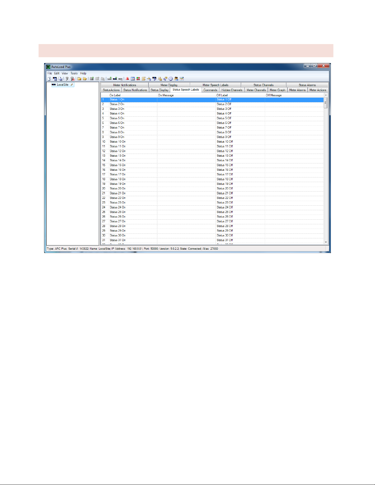
91
STATUS SPEECH LA BE LS
When an RSI is installed, the settings on the Status Speech Labels tab assign pre-recorded vocabulary to each
status channel. The process for configuring status ON and OFF speech labels is the same as for metering: click the
[…] icon at the right side of the “On Message” or “Off Message” field to assign prerecorded vocabulary.

92
COMMANDS
To configure command channels, select the Commands tab.
MOMENTARY OR LATCHIN G RELAYS
All ARC Plus Touch relays can be configured as either momentary or latching. Make this selection under the
Command Type heading. Momentary relays are energized for the duration configured under the Command
Duration heading. Latching channels are energized until the opposing relay is activated (i.e. when a channel is
latched in the “raise” state, the raise relay is energized until the lower relay is activated).
COMMAND DURATION
The command duration setting determines the pulse duration for a momentary command.
COMMAND LABELS
Command labels appear on the touch screen, on the web page, and in AutoPilot
software. The touch screen raise and lower buttons provide 12 characters for
the command label (2 rows of 6 characters each. In AutoLoad Plus, hover inside
Raise label or Lower label field and then click […] next to the label text to open
the Command Label. Enter the channel label and click OK.
LCD COLORS
The backlight colors for the raise and lower labels can be configured to be red, green or amber. Use the dropdown
lists under the Raise Button Backlight Color and Lower Button Backlight Color headings to configure these colors.
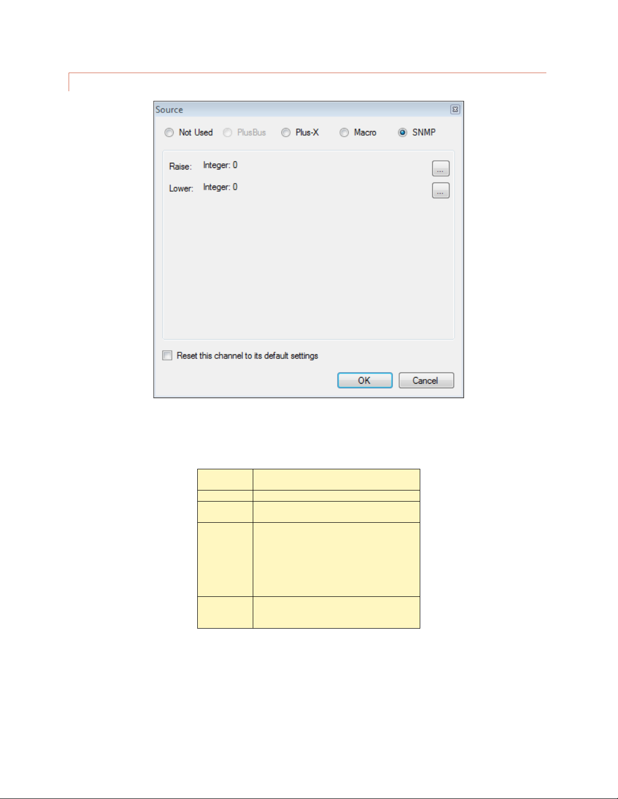
93
COMMAND SOURCE
Commands are used either to operate relays in Plus-X devices, to start/stop the execution of macros, or to control
SNMP devices. In AutoLoad Plus, hover over the source column and click the […] button on the right side of the
Source column. There are four options:
Not used
Selected by default. Indicates that a
command channel is not in use.
PlusBus
Not used in version 5.
Plus-X
This option allows you to map a Plus-X
channel. This is the most common selection.
Macro
This option allows you to run a macro by
issuing a raise or lower command to the
channel. Two different macros may be
assigned to a channel’s respective raise and
lower commands.
Note: You can always run/stop macros from
the macro list.
SNMP
This option instructs the ARC Plus to send
SNMP messages by issuing raise or lower
commands to the channel.

94
USING A COMMAND TO SEND AN SNMP MESSAGE
SNMP has been selected in the Source dialog shown above. A unique SNMP message can be sent
corresponding to a Raise command on this channel, and a different SNMP message can be sent based on a
Lower command on this channel. To assign the desired SNMP parameter to one of these actions, click on
the corresponding dot box: The SNMP Command Binder window will be displayed.
Clicking on the Browse button in the SNMP Command Binder invokes the SNMP MIB BROWSER to
identify the desired SNMP parameter (OID) for the raise or lower function. The Command Binder also lets
you specify the data type and data value to be sent to the SNMP device along with the selected OID.
Inclusion of Meter Channel values and Status Values as SNMP command values enables development of
sophisticated dynamic interactions and automated functions.

95
VI RTUAL CHANNELS
PRIMER
Virtual Channels are a very flexible tool used to synthesize meaningful data from simple inputs. As a simple
example, if you have a temperature probe in the transmitter room (or intake plenum) and a stack probe in the
exhaust plenum, a virtual channel can be used to show the heat rise. A more complex example would be a VSWR
calculation.
Any unused channel can be used as a virtual channel. Here’s how:
1
In AutoPilot, go to the Meter Channels or Status Channels tab and click
the […] icon under the Source heading to access the Source dialog box.
2
Click on the Virtual Channel radio button to make this a virtual channel.
3
Enter the Virtual Channel Expression as desired in the field provided.
The expressions can be as simple as a constant value or as
complex as a VSWR calculation. If you created a virtual
channel and typed 100 in the expression field, that channel
would always read 100. Typing 50 + 50 would do the same
thing.
The terms and operators in the expressions can be any of the
types listed on the source page. M1, for instance, represents
the current value of the first meter channel. You could, if you
like, display the sum of meter 1 and meter 2 on another
channel by this expression:
If Meter 1 is ambient temperature and Meter 2 is stack
temperature, we can label Channel 3 “Delta T” or “GAIN” and
set the expression to M2 – M1. Now we can see at a glance
what the temperature differential is. You can even set a limit
on the differential and have it alarm if too high. Here it is in
AutoPilot on a custom view:
Virtual status channels create an ON condition when the expression
evaluates to true, and OFF if it does not. The expression can include metering values with equality operators like
M3 > 50. This would turn the status on if the meter channel exceeds 50.
Status values can be used as well. S1 AND S2 would evaluate true if both Status channels 1 and 2 are ON.
Heat Gain as shown in AutoPilot

96
EXAMPLES
STATUS VALUES IN MET ER CHANNELS
Status values are represented by 1 for on and 0 for off. This is useful when a metering channel needs to change
depending on the mode of operation. If either of two transmitters can feed the antenna and there is no power
meter after the coax switch, it would be nice to know what the power out was regardless of which transmitter is
on. Assume the following input conditions:
Status 1 is true when TX1 is ON ANT
Status 2 is true when TX2 is ON ANT
Meter 1 is TX1 Output Power
Meter 2 is TX2 Output Power
Set Meter 3 as a virtual channel with this expression:
S1 * M1 + S2 * M2
Since S1 is either 1 or 0, the first term will either be zero or the value of
meter 1. Same for S2 in the second term.
Now, whenever S1 is true, we’ll see input 1 on channel 3, and whenever S2 is
true, input 2 will be displayed. Channel 3 will always show output power
regardless of which transmitter is on.
MIN/MAX/AVERAGE
The ARC Plus Touch allows for setting metering channels to normal, minimum, maximum or average. Typically, the
real-time value is also to be displayed, so put any desired calculated values on virtual channels. In fact, you could
devote 4 channels to one input, using separate virtual channels for min, max and average. One channel would be
the actual input, say Meter 1, and the other three would be set to virtual, all with an expression of M1 but with the
sample type set differently as described in SAMPLE TYPE AND TIM.
TRANSMITTER EFFICIE NCY
Transmitter efficiency is easy to calculate in real time using a virtual channel.
Here are the three actual inputs you’ll need:
Meter 1 is Input Voltage
Meter 2 is Input Current
Meter 3 is Power Out
And here is the expression for a virtual channel calculating efficiency:
M3 / M2 / M1 * 100
This assumes watts, amps and volts. (The factor of 100 converts the output into percent.) You will have to make
further adjustments for kW, KV and mA as appropriate.
We could have simply
added M1 and M2, but that
doesn’t allow for a
transmitter being operated
into a dummy load.

97
METER VALIDATION
If two methods of measuring output power vary by more than a small amount, it brings metering validity into
question and should be investigated. If you have more than one way of determining output power, you can
validate your meter samples by constantly comparing in real-time. Here is an example:
Meter 1 is XMTR Power Out
Meter 2 is ANT Power In
The expression to compare the two values (in percent) is:
(M2 – M1)/M1*100
You can now set an alarm on this channel to be alerted when the difference is more than, say, 1 percent. You could
also compare direct and indirect power and do the same thing, but alarms on efficiency work just as well.
STATUS BASED ON ANA LOG LIMITS
You can also set a channel based on analog limits. While you would normally alarm on limits, there may be
situations where you would prefer to log values as a status rather than an alarm. Here is an example assuming
Meter 1 is Power Out. A status channel is set to be virtual and the following expression is entered:
(M1 > 90) AND (M1 < 105)
STATUS FOR MULTIPLE EVENTS
Sometimes it is nice to have a single status channel alert us to one of several possible problems. A virtual status
channel does this very well.
Assume the following conditions all indicate trouble:
Status 1 = Silence Sense
Meter 1 (Power Out) < 4500
Meter 2 (Temperature) > 90
Here is our master status channel for the site:
S1 OR (M1 < 4500) OR (M1 >90)

98
COMMAND FAULT CHECK ING
When a command is issued remotely, there are numerous things that can keep the desired result from occurring. If
a status signal exists, there is an easy way to compare the fact that a relay was energized and the action actually
took place. Assume the following:
Command 1 = TX ON AIR (latching)
Status 1 = TX ON AIR
Here is the virtual channel expression for a fault indication:
R1 XOR S1
R1 represents the state of the relay for channel 1 which is set to latch the transmitter on the air. S1 represents the
status from the transmitter confirming that it is actually on. XOR is the exclusive OR operator meaning that either
one or the other condition is true but not both. The truth table looks like this:
R1
S1
Result
Condition
0 0 OK
TX off
0 1 Fault
TX on with no command!
1 0 Fault
TX command on but no response
1 1 OK
TX on
If no status signal is available, there may be a metering value you can use like this:
R1 XOR (M1>90)
To prevent false alarms at startup, add a little delay to the alarm.
VSWR COMPUTATION
Displaying VSWR on an ARC Plus is easy using virtual channels.
Meter
Source
Label
Units
1
Plus-X
Forward Power
kW 2 Plus-X
Reflected Power
W 3 Virtual Channel
Rho*
4 Virtual Channel
VSWR
*Reflection coefficient, not usually displayed but needed for calculation
Meter 3:
SQRT (M2 / (M1 * 1000))
Meter 4:
(1 + M3) / (1 – M3)

99
MA CROS
The ARC Plus features on-board macros for automatic responses to conditions at the remote site, scheduled
activities based on time-of-day, or calendar-based routines that reference pre-configured calendar times.
MACRO PRIMER
Macros consist of a series of individual lines that generally act in sequence. There are only three types of macro
lines: branching, actions and IF statements.
BRANCHING
Branching controls the order in which macro instructions are executed. Without branching, we would merely have
a list of steps to follow which would play back much like a recording. With branching, it is possible to make the
macro behave differently under different conditions.
There is only one branching instruction in the macro language, goto, but it appears in two different forms. On a
line by itself, goto is used to branch to a different line like this: Goto line 1.
It also appears as part of an IF statement: If (something) = (something else) goto line 4.
Branching also allows looping in the macro. This is useful for constantly checking on something or performing an
action until some result is achieved. To perform a loop, put a goto on the line following the steps to be looped
followed by the line number of the first action. If there are no if statements branching out of the loop, it is an
infinite loop. If the action needs to end when a value is reached, include an If statement in the loop which includes
a goto to a line outside the loop (such as an end statement at the end of the program).
ACTIONS
Actions include physical things like
Raise "TX-A RF ON" on site "BURK-FM" for 00:00:01
and more virtual things like Decrement memory 8 or
Wait for 00:00:01.
Actions also include “Set” functions like
Set Test1 on BURK-FM = 100 or
Set high critical of "TX-A FWD" on "BURK-FM" to 105.
For a complete set of actions Click or turn to MACRO EXPRESSIONS.
IF STATEMENTS
When a macro is started, it executes lines sequentially unless it is redirected by a goto. Each If statement has a
comparison which is evaluated for true or false. A goto is included in every If statement, but it is conditional on
the results of the comparison. If the comparison is true, the IF statement will branch the macro to another line. If
not, the macro will simply continue on the next line.
You do not have to type these
lines into the macro!
The Macro Editor is “point and
shoot” so there is little to
remember and no such thing as
a syntax error.

100
Consider this scenario: We always want to make sure the Dummy Load pump or fan is turned on before putting
the transmitter into it. Our “Test TXA” routine might contain something like this:
1 : If status of "LOAD OFF / LOAD ON" on site "BURK-FM" = "LOAD ON", goto line 4
2 : Raise "LOAD ON" on site "BURK-FM" for [default]
3 : Wait for 00:00:30
4 : Raise "TX-A RF ON" on site "BURK-FM" for [default]
At the start of this macro, if the load is already running, we’ll go directly to starting the transmitter. If the load isn’t
on, we’ll turn it on and wait 30 seconds before starting the transmitter. (Tube filaments could be done the same
way.)
Looking at this macro line by line, the first line is obviously an IF statement. The comparison we are evaluating is a
status input being compared to a literal value. The status input is labeled "LOAD OFF / LOAD ON" and the
literal we are comparing with is "LOAD ON". If the expression evaluates to true, we are branching to line 4. In
plain English, “If the load is on, then skip to line 4, else continue on line 2.”
Line 2 doesn’t get executed unless the branch from line 1 is not taken. That is, if the test for the load being on
fails, we don’t take the branch to line 4 but rather continue on sequentially, executing Line 2 which is a Raise
command. This line contains the channel and site information as well as the duration of the command.
After the Raise command the macro will wait for 30 seconds.
Finally we get to line 4 and turn on the transmitter with another Raise command.
There are many types of IF statements and they are listed in MACRO EXPRESSIONS.
 Loading...