


BK3'AND
BK3'PWS. "
"BANDSAWS'
.
~ Mk. II \ .
\
.
,
.'.:
.;
..
:.
.'.'.'..
',_,".:.q:'
.
,
.
,
'
..
,-~"'
.
. t'"
.•• -. _,.1 '.
·<.Y·
o ,.."
• I~. •
I
i
/
..
'.'
.
.
.
'
-. ,Specific,ations and
op~"ating ,/'"
Instructions . '/'.
.
'
BU
.I

These products are made to the'
highest possible standards. They are
fully guaranteed and suitable for both
professional and DIY use.
This bandsaw i's one of the most
versatile power saws available and
copes equally well with either straight
or intricate contour cuts on a wide
variety of materials.
The BK3 PLUS Mk. II includes
accessories to enable it to be
converted for use as a jig or fretsaw
thus providing three saws
in
one.
These accessories, whilst. supplied
as standard with the BK3 PLUS
Mk. II are available as optional extras
for the BK3 Mk II.
CON FORM'S TO
RADIO AND TV
SUPPRESSION
REQUIREMENTS
OF BS800: 1977
Key Featu res
Two blade speeds:
106m per min (350ft per min).
396m per min (1300h per min).
12" Throat and 3" depth of cut.
Table tilts through 45°
Range of 5 blades for wide variety of
materials.
Rugged die cast aluminium construction.
Completely self contained with built-in
motor, c/w power take off facility.
Mounted on base plate equipped with
rubber feet for stability.
Easily portable.
Compact and easily stored.
Unique safety cut off mains switch/dust
flap. .
Ideal for use in:
The home workshop
. General industrial use, trade and
engineering, maintenance and pattern
shops
Handicraft departments of schools and'
technical colleges
/
.'
/
)
/
/
/
/
..
\
,
'\
\
• 2
\
For a wide variety of applications:
Joinery, cabinet making
Model making
Household maintenance
Pattern making
Boat building
Shop fitting. exhibition and window
display
Manufacture of plastic components
Coach trimming, motor repairs.
Sandingllinishing
Onawide variety
of
materials:
Hardwoods
Softwoods
Chipboard
Mild Steel (up to 25mm thick)
Aluminium
Brass
Soft alloys (up to 75mm thick)
All plastic materials (including Formica,
Wareite, expanded polystyrene, perspex,
and thermo plastic floor tiles)
Leather
Cork
Haro rubber
Preparation for use
Wiring Instructions
Thewires in the mains lead are coloured in
accordance with the following code:
GREEN ANDYELLOW: EARTH
BLUE: NEUTRAL BROWN: LIVE
As the colours of the wires in the mains
lead of this appliance may not correspond
with the coloured markings identifying the
terminals in your plug proceed as follows:-
The wire which iscoloured green-and-
yellow must be connected tothe terminal
which ismarked with the letter 'E' or by the
earth symbol VW or coloured green or
green-and-yellow.
THIS APPLIANCE MUSTBE EARTHED
The wire which iscoloured blue must be
connected to the terminal which is marked
with the letter'N' or coloured black.
The wire which iscoloured brown must be
connected to the terminal which is marked
with the letter'L' or coloured red.
I!
a 13 amp (BS1363) plug is used a3 amp
fuse should be fitted,ifany other type 01
plug is used a 5 amp fuse must be fitted

j
~.
Fitting the saw table
1. Fit the semi-circular mounting arc to
the underside of the Bandsaw table
using the two screws provided.
2. Remove the table locking wing nuts
and washers from the two studs at the
rear of the machine and ensure the
angle indicator does not restrict the
table from being fitted
3. Hold the table horizontal with its slot in
Iine with the back of the blade. Carefully
gUide the table into position so that the
slot is towards you and the studs both
protrude through the slot in the mount-
ing arc underneath the table.
4. Replace the table locking wing nuts
with the washers beneath them. Press
down lightlyon the table to keep it in
contact with the table level adjustment
cam while tightening the wing nuts.
5. Set the angle indicatorto read 0" and
secure.
6. Check that the coloured centre plate
insert is correctly posiltoned in its
recess and that its upper surface is
flush with that of the table.
7. The table may be tilted at any angle
required up to 45
0
;
the angle is
Indicated on the mounting arc. To return
It to the nonzontai bnng the underneath
of the table back into contract with the
cam. A set squareISuseful to check the
level of the table In relation to the saw
blade. Should the table not be square to
the blade release the screw holding the
cam and adjust the table. Then push the
cam up to the table and re-tighten.
To assist in the control of the work
positioned on the table two fences are
available as optional accessories:
1. The Rip Fence is for rip and cross
cutting.
2. The Mitre Fence is invaluable for all
applications involving mitre joints.

4
The Blade
For optimum oertorrnance the blade
should be checked for tension and track-
ing prior to itsfirst use, when fitting a
replacement blade, and at regular inter-
vals thereafter. Both of these adjustments
require the cover plate to be removed.
This is easily achieved by rotating by a
Quarter of a turn each of the three locking
screws hOldmg the cover plate to the main
frame.
BEFORE REMOVING THISCOVERTHE
UNITSHOULDBE DISCONNECTED
FROM THE ELECTRICAL SUPPLY. 00
NOTATIEMPTTO RUN THE MACHINE
WITH THE COVER PLATE REMOVED.
Blade tension
CAUTION: Over-tensioning tends to shor-
ten the life of the blade. The tension should
be released when the machine is not in
use. Blade tension should never be
greater than is necessary to keep Ihe
blade on Itswheels and to transmit the
drive
Toadjust the blade tension turn the ten-
sion adjusting knob clock-wise to
increase tension. As a guide to correct
blade tension, note the curve that the
blade makes as it leaves the top wheel on
Itsway down to the table, screwing clock-
wise on the adiustrnent until the blade
leaves the top wheel in astraight vertical
IIne.At th ISpoint, screw the tension knob
down a further full turn, this should give
sufficient tension under normal
circumstances.
Blade tracking
The blade should always move centrally
over the top wheel. This can be checked
through the track viewing slot in the top of
the bandsaw frame.
Toadjust the blade tracking. manually
rotate the top driven wheel clockwise and
establish the degree of adjustment
required. Turn the blade tracking knob
clockwise (viewed from the rear face) to
cause the blade to track nearer the back of
the bandsaw frame.
Turn the knob anti-clockwise tocause the
blade to track nearer to the front of the
machine. The adjustment is correct when
the blade is moving centrally on the top
wheel as stated previously.

_.
II
.,
Blade guides
Toensure the best results from your
bandsaw the top blade guide assembly
must be set as close to the surface of the
workpiece as possible. This is achieved
simply by releasing the tension to the
blade ~uide adjustment knob and slidl ng
the gUide assembly either up or down to
the appropriate position.
The bottom blade guide assembly should
always be as close as practical to the bot-
tom of the table and only requires adjust-
ment when using the tilt facility.
The blades must run freely in both the top
and bottom guides and these should be
adjusted so that the teeth of the blade just
clear the front edge of the two cyhndrical
r,
guide blocks. The back bearing can then
be adjusted untilitis between O.5mmand
1mm away from the back of the blade.
Changing the blade .
Unscrew the tension adjusting knob
several turns to lower the top wheel
assembly. If thewheel does not move
freely it may be pulled down manua Ily
once the tension ing knob has been
loosened.
Liftthe used blade from the wheels and
carefully guide it through the slot in the
saw table.
Before fitting the new otace check that the
teeth on the blade are pOinting
downwards. If this is not the case, then it is
necessary to turn the blade inside out.
This can be easily achieved bygripping
the blaoe between the thumb and
forefinger of both hands and rotating each
hand in the opposite direction to the other.
Using care guide the replacement blade
through the slot in the table and locate it
on the two bottom wheels. Then rotate the
blade onto the top wheel with aclockwise
motion checking again that its teeth are
pointing both forward and downward,
Screw down the tension adjusting knob
suffeciently 10 keep the blade on the
wheels and position the blade in the top
and bottom blade guides. Now proceed to
adjust the blade tension, tracking and
guides in accordance with the instruc-
tions given previously.
5

Changing the blade speed
Your Bandsaw is supplied in the high
speed mode for cutting wood and
softer materials, and for finishing
operations in wood or metal using the
sandingflinishing belt. For operations
involving mild steel, alloys etc. the slow
speed mode is required to avoid undue
wear of the blade and10provide a
better
finish. .
To change the speed the following
procedure should be followed:
1. DISCONNECTTHE MACHINE FROM
THE MAINS SUPPLY
2.
Remove cover
plate
3. Slacken blade tension and remove
blade
4. Slacken off both motor secu ring
screws, swing motor forward and
remove timing ben
5. Remove screw from the centre of the
bottom/front wheet and remove wheel
6.
Fitalternative pulleyand secure with
screw
7. Fillonger timing belt around the
periphery of the front wheel and over
the motor pulley .
8. Swing the motor backwards toapply
tension to the belt, this is ideally set
when 5mm (3/16") movement occurs
at the centre of the top belt run,when
6
lightly pressed. Tighten motor screws.
I
...
'-~.-"-
9. Refit the blade and replace cover
N.B. When set at the slow speed the blade
runs on the top of the timing belt on the
drive wheel.
Using
the
machine
Rate of feed of work to blade
Rates of feed vary with the matenai being
cut and its thickness. Always allow the
blade to do the work and never apply
undue pressure sufficient to distort the
blade. A little experience will indicate the
correct rates of feed for materials of dif-
ferent hardness and thickness. Forcing
the rate of feed will shorten the life of your
bandsaw blades.
Safety Cut off Switch Cover
Both Bandsaws feature a dual purpose
safety cut oH/dust cover on, the switch.
To SWitch the machine on the cover
must be raised and the switch
depressed. However, the machine may
be switched
oH
easily and quickly by
merely tapping the yellow safety flap.

High speed materials .
With the machine set at high speeditis
suitable for profile cutting and cross cut-
ting of both hard and soft woods. At the
higher speed you will findthewoodwill cut
very easily and all you refforts can be
directed towards guiding thework past
the blade. On thicker sections of timber
(over 15mm) where a long cut along the
grain is to be made, itmay be desirable to
use the lower speed to obviate the
possibility of stalling the motor.
Low speed materials
The low speed is used primarily for steel
and other metals, but It is also advisable to
use t~e slow speed when cutting
olastrcs over Smm thick. If a high speed is
used when culling thick plastic material
substantial amounts of heat may be .
generated which will tend to weld the plas-
tic together beh ind the blade and even-
tuallycause the machine to stall.
Sanding and
lii'lishing
This is also carried outat the higher speed.
These belts are fitted to the machine in the
same way as the blade. However it is
advisable that the top and bottom blade
guide assemblies be removed completely
to avoid any damage to these items. When
fittin9 the finish ing belt ensure that the lap
joint Inthe belt is as shown in the sketch,
so as to avoid tearing the belt.
Whilst the belt can be used for finishing
operations without having any support to
the back taceot the belt, it is far more
effective if sorndoressure isapplied to this
back face by means of a suitably shaped
piece of wood or similar material.
".
\.
7

,I
t'
8
Maintenance
THIS PRODUCTSHOULD BE DISCON-
NECTED FROMTHE MAINS SUPPLY
WH ILST CARRYI NG OUT MAINTENAN-
CE,ADJUSTMENT OR THE REPLACE-
MENTOFANYWORN PARTS.
The 810 Mk.1I 8andsaw is supplied with
a new, all-British motor.
Manufactured to the most stringent
electrical and mechanical specifications,
it is more powerful than its predecessor
and is equipped with- a a power take-off
paint, at the rear, to accept the latest
Burgess accessory, the Disc Sanding
Attachment.
Contents:-
(i) 180mm
(7")
diameter sanding disc
(ii) Adjustable angle table from
0
0
to 45
0
which accepts the Burgess mitre
fence accessory
The purchase of a Disc Sanding
Attachment will extend even greater
versatility to the range of useful
applications for which your
BK3
Mk,11
may be used. The Attachment is
available now from your local stockist,
part no. 580800.
Cleaning
Dust ejection slots at the bottom of the
frame do much to minimise the accumula-
tion of sawdust but they may become
obstructed after prolonged periods.
Therefore, after every few hours of running,
the front cover plate should be removed
and accumulations of sawdust be
removed both from the interior and from
around the machine, either by brushing,
by blowing with compressed air, or by
removing with a vacuum cleaner.
lubrication
Occasionally apply one or two spots of
good quality machi neoil to the spindles of
each of the three wheels.
ReplaCing
worn
drive belts
With the machine disconnected from the
mains and the blade removed a worn driv-
ing belt may be replaced by slackening
the two motor fixing studs, easing the belt
tension, and running it off both pulleys.
When a replacement belt has been fitted
apply sutlicient tension as described pre-
viously under the section describing
speed change.

,
l
,
Rectifying blade slip
Slade slip may occurifthe outer surface of
the driving belt (which also serves as a tyre
on the driving wheel at slow speed)
acquires a greasy coating from the blade.
This coating may be removed from the bell
and from the other two wheels by wiping
with a cloth which has been dampened in
white spirit.
Blade slip may also be caused by insuffi-
cient blade tension.
To rectify electrical failure
Sould any electrical fault occur, set the
switch on the front of the bandsaw to OFF,
disconnect the bandsaw from 'he electri-
cal supply and refer the matter to a compe-
tent electrician.
BK3 Plus Mk. II - The 3 in 1 Saw
As
a general purpose saw the BK3
Mk. !I can hardly be improved ·upon. But
with the addition of the Fretsaw/Jigsaw
attachment or Circle Cutting and Fence
attachment, available as optional extras
(or included as standard with BK3 Plus
Mk. II), it can be upgraded into a truly
universal three-in-one combination saw,
to expand your scope even further.
Thus, no matter whether you obtain
these attachments at the outset with a
BK3 Plus Mk. II or later, to add to a
BK 3 Mk.
tI,
the method of fitting and
operating them is identical. The only
diHerence is that. with the BK3 Plus
Mk. II, these extras come packed in a
handy plastic storage box, attached to
the frame. This should be unscrewed
before use and the screw holes plugged
with the rubber grommets provided. The
box can then be retained in the
workshop for storage of these valuable
attachments.
Your BK3 Plus Mk. II Bandsaw is
supplied with a new, all-British motor.
Manufactured to the most
9

stringent electrical and mechanical
specifications, it is more powerful than
its predecessor and is equipped with a
a power take-of point, at the rear, to
accept the latest Burgess accessory, the
Disc Sanding Attachment.
Contents:-
(i) 180mm
(7")
diameter sanding disc
(ii) Adjustable angle table from 00to 45°
which accepts the Burgess mitre
fence accessory
The purchase of a Disc Sanding
Attachment will extend even greater
versatility to the range of useful
applications for which your BK3 Plus
Mk.1I may be used. The Attachment is
available now from your local stockist,
part no. 580800.
Fretsaw/Jigsaw attachment
• Fretsawing facility for intricate internal
and external cuts
• Jigsawing Facility for internal and exter-
nal cuts in heavier materials
• Jigsaw blades capable of swinging
through 90° for longer length materials
• Includes fretsaw and Jigsaw blades
• Fretsaw/Jigsaw will cut wood,
10 plastics and light alloys
Method of Attachment
Disconnect 'rom mains. Slacken tension
and remove saw blade.
A
Remove

A.
Oil or grease regularly
B. Adjust to allow free running. Turnover by
hand to test
C.
Fretsaw blade
D. Fretsaw Blade Guide Block - Adjust
to allow the fretsaw blade to run in
the Vshaped channel.
A.
Push on eccentric&bush
11

12
A
For cutting 'rom the front
B.For cutting 'rom the side
-
A
Ensure that the blade guide rests on the
workpiece and is pushed forward to
support the blade.
B

Circle Cutting and Fence attachment
• For repeat circle cutting
• Invaluable for model and toymaking
• Attachment can be adapted for use as a
straight edged fence
This may be fitted to either the left or right
hand side of the top blade guide
assembly.
t. Raise the top blade guide above the
thickness of material to be cut
2. Using the allen key, remove the approp-
riate blade guide block
3. Insert the smaller end01the long bar
into the guide block with the lIal side
towards you. Adjust to the blade and
·tighten the allen screw
4. When the attachment isto be used on
the left of the saw see Diagram
A
5. Feed the material into the blade in a
straight line for a distance equal to the
recuued radius of circle.
6. Lower the top blade guide assembly
until the pin pierces the material. Then
tighten blade guide clamp knob.
7. Switch on and rotate the material to form
a Circle. ,
3
Place Trammel Pin Casting onto the long
rod usmg the hole nearest to the pin.
Adjust to the eucre you require. then
~Ightenthe allen screw. Make sure the pin
IS porntmq downwards and vertical.
When the attachment isto be used on the
right of the saw blade see Diagram B.
Diagram B
I •
14
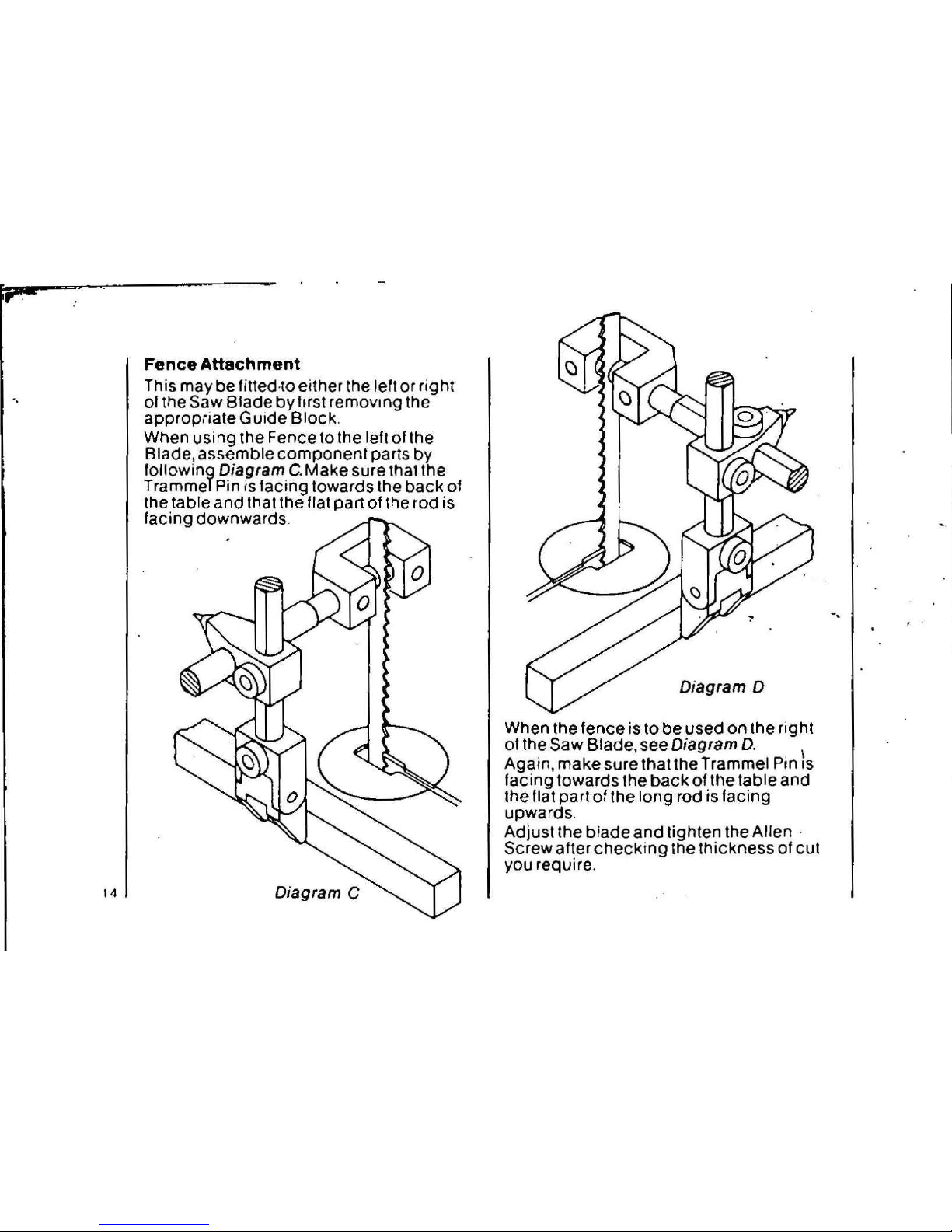
Fence Attachment
This may be tittedto eitner the left or right
of the Saw Blade byfirst removing the
appropnateGuide Block.
When using the Fence to the left of the
Blade, assemble component parts by
following Diagram C.Make sure that the
Trammel Pin is facing towards the back of
the table and that the flat part of the rod is
facing downwards.
Diagram 0
When the fence is to be used on the rig hi
01the Saw Blade, see Diagram D. \
Again, make sure thai the Trammel Pin
IS
facing towards the back of the table and
the flat part of the long rod isfacing
upwards.
Adiust the blade and tighten the Allen·
Screw after checking the thickness of cut
you require.
.,
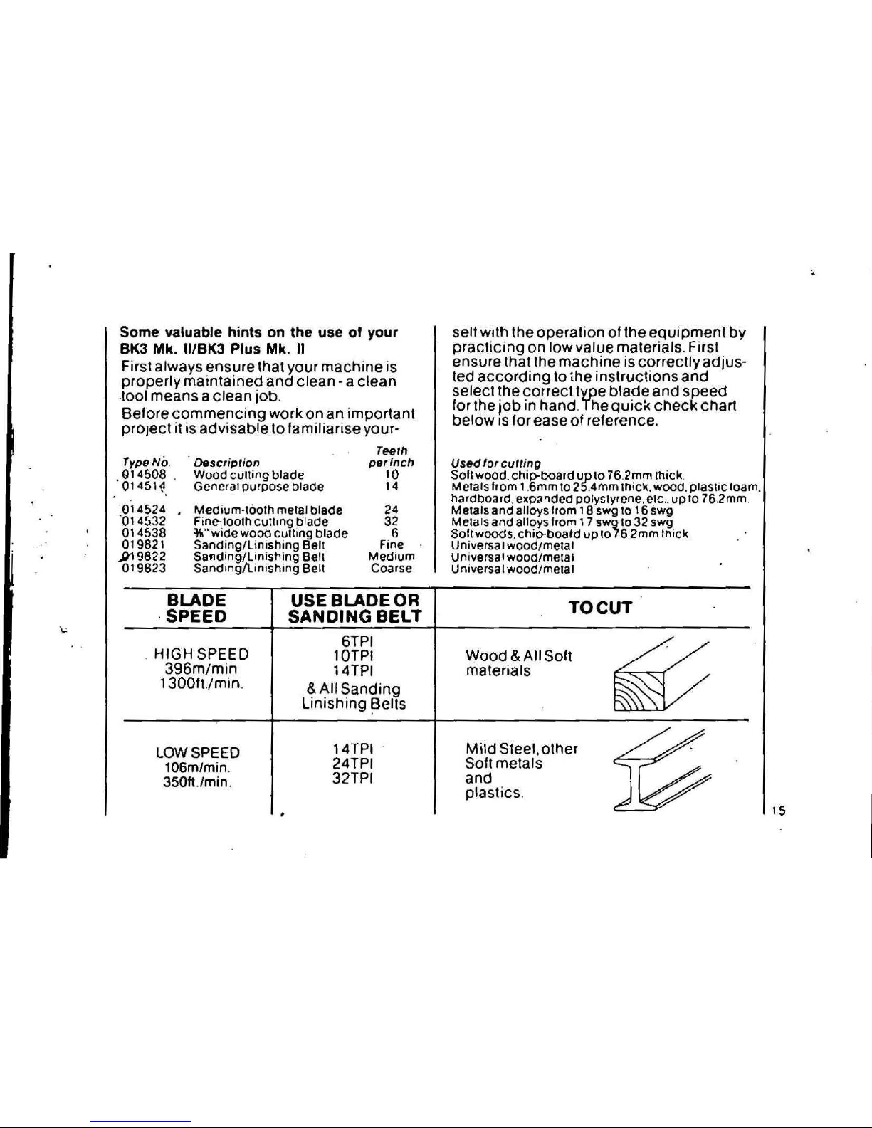
Some valuable hints on the use of your
BK3 Mk. II/BK3 Plus Mk. 11
First always ensure that your machine is
properly maintained and clean -a clean
.toot means a clean job.
Before commencing work on an important
project it is advisable to familiarise your-
Type
No.
. Q14508 .
01451~.
014524
'014532
014538
019821
;>19822
019823
Description
Wood culling blade
General purpose blade
Medium-tooth metal blade
Fine-tooth cutllng blade
~"wide wood cutting blade
Sanding/Linishing Belt
Saflding/Linistling Belt
Sanding/linishing Belt
Teet"
per Inch
10
14
24
32
6
Fine
Medium
Coarse
self with the operation01the equipment by
practicing on low value materials. First
ensure that the machine is correctly adjus-
ted according to the instructions and
select the correct type blade and speed
for the iob in hand. The
quic«
check chart
below IS for ease of reference.
Used for cutting
Solt wood. chip-board up\076.2mm Ihick.
Metals from 1.6mmto2S.4mm thicl(,
wooo.
plastic loam.
hardboard, expanded polystyrene, eic., up to 76.2mm
Me.als and alloys tram 18 swg to 16 swg
Metals and alloys from 17 swg to 32 swg
Sol. wOOds.
chio-noatd up
to76.2mm Ihick
Universal wood/metal
Universal wood/metal
Universal wood/metal
BLADE
.SPEED
USE BLADE OR
SANDING BELT
TO CUT
. HIGH SPEED
396m/min
1300ft./min.
6TPI
lQTPI
14TPI
& All Sanding
Linishing ~elts
14TPI
24TPI
32TPI
LOW SPEED
106m/min.
350ft.lmin.
Wood&All
Soft
materials
Mild Steel,other
Soft metals
and
plastics.
15

16
BK3 Mk. II and BK3 Plus Mk. II
Cutting with the bandsawISstraight
tor-
ward - simply by g~iding thework mto the
moving blade, always ens unng that
tingers are well ctea rof the blade. If a cut is
required near the edge of a material one
hand can beused toguide it,whilsta
piece of wood held in the other hand can
add valuable suport and assistance wilh
complete safety.
In all cutting operations the work should
befed intothebladeata steady rate and
back trackinq (i.e.pulling the work back
from the moving blade) should be
avoided, or at least reduced to a minimum.
This is best accomplished by planning
your cuts beforehand.
Bu rgess bandsaw blades are very flexible,
but very complicated cuts and small
radius curves are best accomplished with
the aid of pre-drilled holes combined with
a few tangential or radial cuts. This techni-
que will achieve excellent results without
putting undue tension on the blade and
blade gUide assembly.
Hints on the use of BK3 Plus Mk. II
For internal cuts using either the Fretsaw
or Jigsaw blade, a hole must be drilled in
the material through which to teed the .
appropriate blade.
Toaccomplish this, raise the upper blade
gUide assembly as far as possible and
feed the material over the fitted blade.
When using Ihefretsaw blade on materials
over
Va"
thick, u.s advisable to feed the
blade through the material, prior to fitting
to the machine, to avoid damaging the
blade.
With the material in place the upper blade
guide should then be lowered to the
worksurlace to provide adequate support.
Cutting can then commence, taking care
not to force the rate of feed. Letthe saw do
the work.
Where the internal cut is particularly com-
plex and intricate it is advisable to pre-dri II
holes in strategic positions to facilitate
sawing.
The jigsaw blade is particularly useful for
heavier materials and can be pivoted
thrOUQh45° to accommodate longer
material. The upper blade guide support is
not required for the heavier gauge jigsaw
blade.
Advisory service
We are very willing to advise on, and give
assistance in developing techniques for
carrying out unusual culling operations.
We are also always interested to know of
any special techniques which have been
developed independently by bandsaw
users among our customers.

Tooisthatturn passing
interest into lasti ng
pleasures
No matter Ifa job is tackled reluctantly,
simply because it is a chore that has to be
done, or with enthusiasm because it prom-
ises to be a pleasure, the chosen tool can
make or mar both the experience and the
results.
That's why Burgess take great pains to
ensure that every tool they sell brings its
owner the satisfaction of a job well done,
over and over again.
Byeasing your task, improving your skills
and increasing your enjoyment, they have
the habit of bringing out creative and prac-
tical abilities you never knew you had, so
turning fleeting interests mto fife long
hobbies
Artist or craftsman, amateur or pro-
fessional, Burgess have a way to help
active individuals of all ages realise their
potennai to the full.
Tools available from Burgess include:
BANDSAWS
CIRCULAR SAWS
SITE SAWS
MITRE SAWS
ENGRAVERS- VIBROAND ROTARY,
TOOLS AND KITS
SOLDERING IRONSt5.2S,40WATI
AND2SWATIKIT
SOLDERINGAND CRAFT KIT
SPRAYE RS -AI RLESS AN D
COMPRESSOR
BENCH GRINDERS •
SHARPENERS
12V ~C ROTARYTOOLS -THE ROTOOL
RANGE
GUARANTEE
Burgess Power Tools guarantee their pro-
ducts for one year from the date of
purchase. Anydefect during this period
not due to accident or abuse will be
repaired free of charge. The statutory
rights of the consumer are not affected.
Burgess Power Tools Ltd.
Sapcote, England. LE-"96JW

/
BK3 SPARE PARTS LIST
Key No.
Part
No.
Description
I
I
014823
Timing Pulley&Rollpin
I
12 019804
Timing Belt. 204 XL
(Low Speed)
12a 019805
Timing Belt, 120 XL
,
"
(High Speed)
13
01 1100 Top Wheel Casting Assy
14
011106
Securing Bolt
~
"
15
014814 Wheel Shaft (2)
15a 014824
Wheel Shalt&Wheel Shaft Screw
16
014815
Circlip (2) .
17 01II 10
Washer •
18
01,111
Lock Nut
~
19 011200
Tension Knob Assy
...
20
011211 Securing Knob
'~.
<,
y~.~;,
011300
Tracking Knob Assy
019913
Blade Shield Clamp
23
012000 Bolt
24 012206
Lock Washer
25 012400
Switch
.....
..
26
012500
Switthbox
27 012600
Screws (3)
0,
&§
28 012801
Cable
29
250150
Cable Clamp
30 •
013100
Terminal Block
~-.KeyNo. Part No. Description
31---010105 Quarter turn cover
I 019910 Frame
plate lasteners (3)
2 ·014811
Pointer
'.
32 013701
MOlor Screws
I
..
'
.
Screw
33
013900
Trunion Stud (4)
3
010206
Centre Plate
34 014100
WingNut (2)
4
,
010S11
Table c/w Centre Plate
35
014300 Cam
5 019738
Base Plate c/w
36 019911
Frame&Base complete
..
6
010112
Base edge finishing strip
37
250151
Cable Clamp Screw
7 019912 Cover Plate
38 019500
Upper Blade Guide Assy
8 019732
Motor (220/240V 50Hz)
,
39
700073
Guide Blocks (Set 4) + Centre Plate
019756 Motor (1OOV50Hz)
40
019620
Bearing Shaft)
t~
019746
MOlor (1DOV60Hz)
Bearing
)
f
019745
Motor (1 10V 50Hz)
Circlip )
9 010704
Wheel
I'-
41 019600
Lower Blade Guide Assy
10
010802
Drive Wheel
42 019621
Roller)
(Low Speed)
RoliPin)
10a 019817
Drive Wheel
43
019606 LockNut
High Speed)
•
44
019623
Insulating Pad
•
....
 Loading...