

Page 1
Smartflow®
Mold Temperature Regulator
Operating Instructions
General
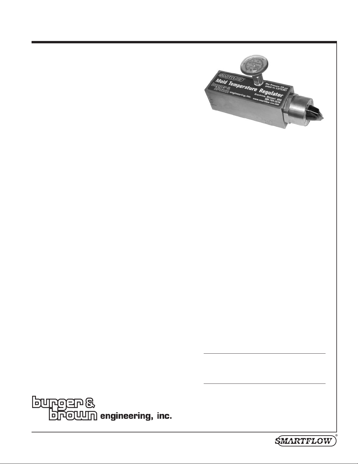
The Smartflow Mold Temperature Regulator controls the temperature
of cooling water exiting a mold, thereby regulating the mold
temperature.
A mold is heated by the resin shot. The heat from the mold is
transferred to the cooling water. The regulator senses the water
temperature and restricts the cooling water flow, giving it time to be
heated by the mold, until it reaches the desired set point. The
regulator valve slowly widens to allow the cooling water to go
through at a rate that will hold the mold temperature at a value that
corresponds to the set point.
Remember that the mold temperature is always hotter than the
cooling water return temperature.
Mode of Operation
When the temperature of the cooling water is greater than the desired
set point, the regulator adjusts the valve opening to increase flow.
When the cooling water temperature is less than the desired set point,
the valve opening closes, decreasing flow. The set point is adjusted
with the control knob on the end of the unit. A thermometer provides
visual indication of the cooling water temperature.
Since every mold is different, data is not available for every
situation. The molder should determine the outgoing coolant
temperature, and make adjustments based on experience.
Flushing
The Smartflow Mold Temperature Regulator incorporates a special
flush feature to remove particles which may become lodged inside.
By turning the control knob fully clockwise, the valve is completely
open. Any foreign particles should be removed by the increased
cooling water flow. After flushing, return the unit to original setting.
Special Notes
Molders are cautioned that the Smartflow regulator will not work for
every mold size. Molders making very small parts may not have
enough heat from the resin shot to heat the mold adequately.
Generally, the regulator can be used where the cooling water supply
is cooler than the water exiting the mold.
Specifications
Regulator
Cooling Water
Set Point Range .....................80° to 120°F
(27° to 49°C)
Accuracy................................±1°F
Thermometer is not as accurate as the operation of
the Mold Temperature Regulator.
Thermometer indicates the coolant temperature
Range.....................................0 to 250°F
(-18 to 121°C)
Accuracy................................±1°F Mid Scale
±2°F Full Scale
Wetted Materials
All wetted parts are Electroless Nickel-Plated
Brass & 303 Stainless Steel. O-rings are Buna-N.
CAUTION
Do not allow the water temperature inside the
Mold Temperature Regulator to exceed 200°F
for more than 30 minutes. Damage to internal
parts will result, and warranty will be void.
4500 E 142nd Street • Grandview, MO 64030 • Tel. (816) 878-6675 • www.smartflow-usa.com
Form #104 (6.16)
Page 2
80 85 90 95 100 105 110 11 5 120
180
280
260
240
220
200
Linear =
mm
inches
Dial The rmomete r
152.4
6.0
38.1
1.50
1/4"NPT inlet
7 Places
85.6
3.37
1/2"NPT
outlet
74.9
2.95
19.1
0.75
Set Point
Scale
38.1
1.50
Adjustment
Housing
19.1
0.75
43.7
1.72
Optional Inlet
Manifold
Set Point
Knob
38.1
1.50
Smartflow® Mold Temperature Regulator
Installation
NOTE: Flush a newly-installed mold to remove
rust and corrosion particles before installing the
old Temperature Regulator.
M
Install the regulator as close to the mold as
possible to reduce variables affecting the cooling
water temperature.
Inlet 1/4"NPT(F)
Outlet 1/2"NPT(F)
1. Connect the water exiting the mold to the 1/4"
inlet or manifold ports of the regulator. “IN” is
stamped next to the inlet on the regulator
body.
Do not over-tighten inlet
connection past 7.6mm/0.3" deep!
2. Connect the return circuit to the 1/2" outlet of
the regulator. “OUT” is stamped next to the
outlet on the regulator body.
3. Move the control knob clockwise until it
stops. Turn the control knob counter-clockwise
to the 120° mark. Continue turning the control
knob counter-clockwise to set the pointer to
the desired cooling water temperature on the
set point scale.
4. Start the molding process. It may take a few
shots to heat the cooling water so the
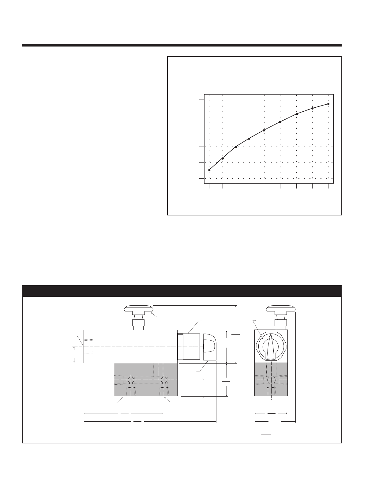
regulator will respond. The graph at right is
provided for reference only, your results may
vary.
Steel Mold Temperature vs.
Exiting Coolant Temperature
in a Laboratory Mold
Steel Mold Temperature °F
Exiting Coolant Temperature °F
Test Set-up
70°F coolant in @ 50 psi
Heat: 2000 Watt 20 sec on/ 10 sec off
Dimensions
2 tel. 800-764-3518
burger & brown engineering
Page 3
mold
Mold Temperature
R
egulator
Return to
Circulating
System
Supply from
C
irculating
System
Zone Control Configurations
mold
Return to
Circulating
System
Supply from
Circulating
System
Mold Temperature
Regulator
Optional
Manifold
mold
Return to
Circulating
System
Supply from
Circulating
System
Mold Temperature
Regulator
Smartflow® Mold Temperature Regulator
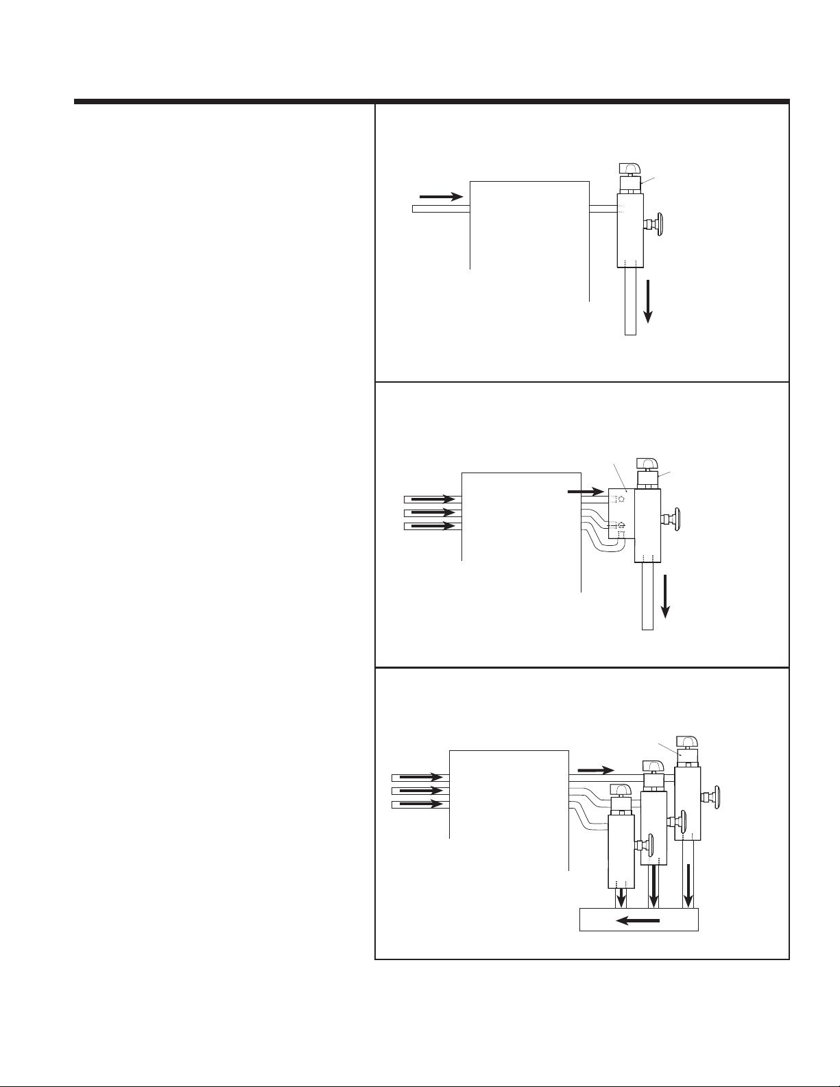
For single zone control
connect the
,
regulator to the return line from the mold as
shown in figure 1.
To control multiple zones to the same
temperature using a single device, connect the
lines to the optional manifold of the regulator as
shown in figure 2.
figure 1
figure 2
To control multiple zones at different
temperatures, connect a regulator to each
separate zone as shown in figure 3.
burger & brown engineering
tel. 800-764-3518 3
figure 3
Page 4
Smartflow® Mold Temperature Regulator
Troubleshooting
Symptom
No flow through the regulator
Very limited flow through the regulator • Check the installation: water exiting the mold
The mold is running too hot • Flush the regulator by turning the control knob
Corrective Action
• Check the water supply.
• Flush the regulator by turning the control knob
fully clockwise to the “flush” position, then
reset to desired set point temperature.
should be connected to the inlet port on the side
of the unit.
• Cooling water is too cold or there is not enough
heat in the mold, add more circuits to the inlet
using the optional manifold. See figure 2.
fully clockwise to the “flush” position, then
reset to desired set point temperature.
• There is too much heat in the mold, separate the
circuits (if using a manifold), use one regulator
per cooling line. See figure 3.
If corrective action fails to correct the problem,
please contact the factory.
Limited Warranty
The limited warranty is void if the Mold Temperature Regulator is disassembled in the field. Return to the factory for reconditioning if flushing is insufficient to clear particles from the inside.
Seller warrants that this product supplied will conform to the description herein stated and that the product will be of
standard quality. This is the sole warranty made by Seller with respect to this product. Seller expressly disclaims any other
express or implied warranties, including, but not limited to, the implied warranty of merchantability and the implied
warranty of fitness for a particular purpose.
Seller shall not be liable for any cost or damages, whether direct, incidental or consequential, including, but not limited to,
any injury, loss or damage resulting from the use of this product, regardless of whether any claim for such cost or damages
is based on warranty, contract, negligence, tort or strict liability. The sole liability of Seller is limited to repairing or
replacing this product.
This warranty shall not apply to any products that have been repaired or altered by anyone other than Seller. The warranty
shall not apply to any products subject to misuse due to common negligence or accident, nor to any products manufactured
by Seller which are not installed or operated in accordance with the printed instructions of Seller or which have been
operated beyond the rated capacity of the goods. Seller states that the product’s useful safe life is 5 years. Actual life may
vary widely depending on operating environment such as temperature, pressure, and chemical exposure.
burger & brown engineering
4 tel. 800-764-3518
 Loading...