

Page 1
®
SINGLE
SH DBC
WITH SMART FUNNEL
Software Version 1.15
and all ending __.15
®
®
INSTALLATION & OPERATING MANUAL
BUNN-O-MATIC CORPORATION
POST OFFICE BOX 3227
SPRINGFIELD, ILLINOIS 62708-3227
PHONE: (217) 529-6601 FAX: (217) 529-6644
To ensure you have the latest revision of the manual or to obtain the illustrated parts catalog, please visit
the Bunn-O-Matic website, at www.bunn.com. This is absolutely FREE, and the quickest way to obtain
the latest catalog and manual updates. Contact Bunn-O-Matic Corporation at 1-800-286-6070 to obtain
a paper copy of the required Illustrated Parts Catalog mailed via U.S. Postal Service.
34025.0000D 02/09 ©2001 Bunn-O-Matic Corporation
Page 2

BUNN-O-MATIC COMMERCIAL PRODUCT WARRANTY
Bunn-O-Matic Corp. (“BUNN”) warrants equipment manufactured by it as follows:
1) All equipment other than as specified below: 2 years parts and 1 year labor.
2) Electronic circuit and/or control boards: parts and labor for 3 years.
3) Compressors on refrigeration equipment: 5 years parts and 1 year labor.
4) Grinding burrs on coffee grinding equipment to grind coffee to meet original factory screen sieve analysis:
parts and labor for 3 years or 30,000 pounds of coffee, whichever comes first.
These warranty periods run from the date of installation BUNN warrants that the equipment manufactured by
it will be commercially free of defects in material and workmanship existing at the time of manufacture and
appearing within the applicable warranty period. This warranty does not apply to any equipment, component or
part that was not manufactured by BUNN or that, in BUNN’s judgment, has been affected by misuse, neglect,
alteration, improper installation or operation, improper maintenance or repair, damage or casualty. This warranty is
conditioned on the Buyer 1) giving BUNN prompt notice of any claim to be made under this warranty by telephone
at (217) 529-6601 or by writing to Post Office Box 3227, Springfield, Illinois 62708-3227; 2) if requested by
BUNN, shipping the defective equipment prepaid to an authorized BUNN service location; and 3) receiving prior
authorization from BUNN that the defective equipment is under warranty.
THE FOREGOING WARRANTY IS EXCLUSIVE AND IS IN LIEU OF ANY OTHER WARRANTY, WRITTEN OR
ORAL, EXPRESS OR IMPLIED, INCLUDING, BUT NOT LIMITED TO, ANY IMPLIED WARRANTY OF EITHER
MERCHANTABILITY OR FITNESS FOR A PARTICULAR PURPOSE. The agents, dealers or employees of BUNN
are not authorized to make modifications to this warranty or to make additional warranties that are binding on
BUNN. Accordingly, statements by such individuals, whether oral or written, do not constitute warranties and
should not be relied upon.
If BUNN determines in its sole discretion that the equipment does not conform to the warranty, BUNN, at its
exclusive option while the equipment is under warranty, shall either 1) provide at no charge replacement parts
and/or labor (during the applicable parts and labor warranty periods specified above) to repair the defective
components, provided that this repair is done by a BUNN Authorized Service Representative; or 2) shall replace
the equipment or refund the purchase price for the equipment.
THE BUYER’S REMEDY AGAINST BUNN FOR THE BREACH OF ANY OBLIGATION ARISING OUT OF THE SALE OF
THIS EQUIPMENT, WHETHER DERIVED FROM WARRANTY OR OTHERWISE, SHALL BE LIMITED, AT BUNN’S
SOLE OPTION AS SPECIFIED HEREIN, TO REPAIR, REPLACEMENT OR REFUND.
In no event shall BUNN be liable for any other damage or loss, including, but not limited to, lost profits, lost sales,
loss of use of equipment, claims of Buyer’s customers, cost of capital, cost of down time, cost of substitute
equipment, facilities or services, or any other special, incidental or consequential damages.
BrewWISE, BrewLOGIC, BrewMETER, BrewWIZARD, Bunn Gourmet, BUNN Gourmet Ice, BUNN Pour-O-Matic, BUNN,
Bunn-OMatic, Bunn-O-Matic, BUNNlink, BUNNserve, BUNNSERVE, BUNN Espress, Cool Froth, DBC, Dr. Brew, Dual, EasyClear, EasyGard, Easy Pour, FlavorGard, Gourmet Ice, Gourmet Juice, High Intensity, IMIX, Infusion Series, Intellisteam,
Quality Beverage Equipment Worldwide, The Mark of Quality in Beverage Equipment Worldwide, My Café, PowerLogic,
Safety-Fresh, Scale-Pro, Silver Series, Single, Smart Funnel, Smart Hopper, SmartWAVE, Soft Heat, SplashGard, System
III, ThermoFresh, 392, AutoPOD, AXIOM, Beverage Profit Calculator, Beverage Bar Creator, BUNNsource, Coffee At Its
Best, Digital Brewer Control, Nothing Brews Like a BUNN, Pouring Profits, Pulse Wave, Signature Series, Smart Heat,
Tea At Its Best, The Horizontal Red Line, Titan, Ultra, are either trademarks or registered trademarks of Bunn-O-Matic
Corporation.
INTRODUCTION
This brewer incorporates a wireless interface system that allows the DBC Grinder to load certain information into the "programming chip" located inside the handle of the funnel. This information includes the name
of the coffee ground and what batch size will be brewed (small, medium, or large). Once the correct name and
amount of coffee is ground, the funnel is loaded into the brewer. The information from the funnel handle is then
transferred into the brewer. The brewer then takes this information and dispenses the amount of water preset in
the brewer for that particular coffee name and batch size. The brewer can also be programmed to adjust different
functions of the brewing process, such as brew temperature, brew volumes, bypass percentages, pulse brew,
etc. This allows the operator to program a certain "recipe" for each coffee name to be brewed.
Page 2
34025 012609
Page 3

TABLE OF CONTENTS
User Notices ...............................................................................................................................4
Electrical and Plumbing Requirements .......................................................................................5
Operating Controls ......................................................................................................................6
Initial Setup .................................................................................................................................7
Coffee Brewing ............................................................................................................................7
Cleaning ......................................................................................................................................7
Glossary ......................................................................................................................................8
PROGRAMMING ........................................................................................................................9
Programming Switches ...............................................................................................................9
Programming the Brewer ..........................................................................................................10
PROGRAM FUNCTIONS (LEVEL 1) Brew Lockout ...................................................................10
PROGRAM FUNCTIONS (LEVEL 2) ...........................................................................................11
Set New Recipe (using a Smart Funnel
Set Brew Volumes ............................................................................................................12
Set By-Pass Percentages .................................................................................................13
Set Pulse Brew Times ......................................................................................................13
Set Preinfusion Times ......................................................................................................13
Set Drip Times .................................................................................................................14
Set New Recipe (using a Recipe Card) ............................................................15
Set New Recipe (no Smart Funnel® or G92T DBC Grinder) .................................................16
Review Recipes/Modify Recipes/Set up No Name Coffee ...................................................17
Set Brew Volumes ............................................................................................................18
Set Bypass Percentages ...................................................................................................19
Set Pulse Brew Times ......................................................................................................20
By Example ...............................................................................................................22
Enter Times ...............................................................................................................23
Set Preinfusion Times ......................................................................................................24
Set Drip Times .................................................................................................................25
Enable Ads ............................................................................................................................26
Set Temp (Brewing Temperature) ..........................................................................................26
Set Ready (Ready Temperature) ............................................................................................26
Refill (Adjust Sensitivity) .......................................................................................................27
Spray Oz/M (Read sprayhead flow rate) ................................................................................27
Bypass Oz/M (Read bypass flow rate) ...................................................................................27
Calibrate Flow .......................................................................................................................28
Calibrate Sprayhead Flow .................................................................................................28
Calibrate Bypass Flow ......................................................................................................29
Brew Counters (View/Reset) ..................................................................................................30
Funnel Detect ........................................................................................................................30
Server Detect ........................................................................................................................31
Service Tools .........................................................................................................................31
Test Outputs (Components) .............................................................................................32
Test Switches ...................................................................................................................32
Test Servers .....................................................................................................................33
Test Frequency ................................................................................................................33
Factory Defaults (Reset) .......................................................................................................34
Troubleshooting ........................................................................................................................35
Schematic (Wiring Diagram) .....................................................................................................46
®
and G92T DBC Grinder) .......................................12
Page 3
34025 012004
Page 4
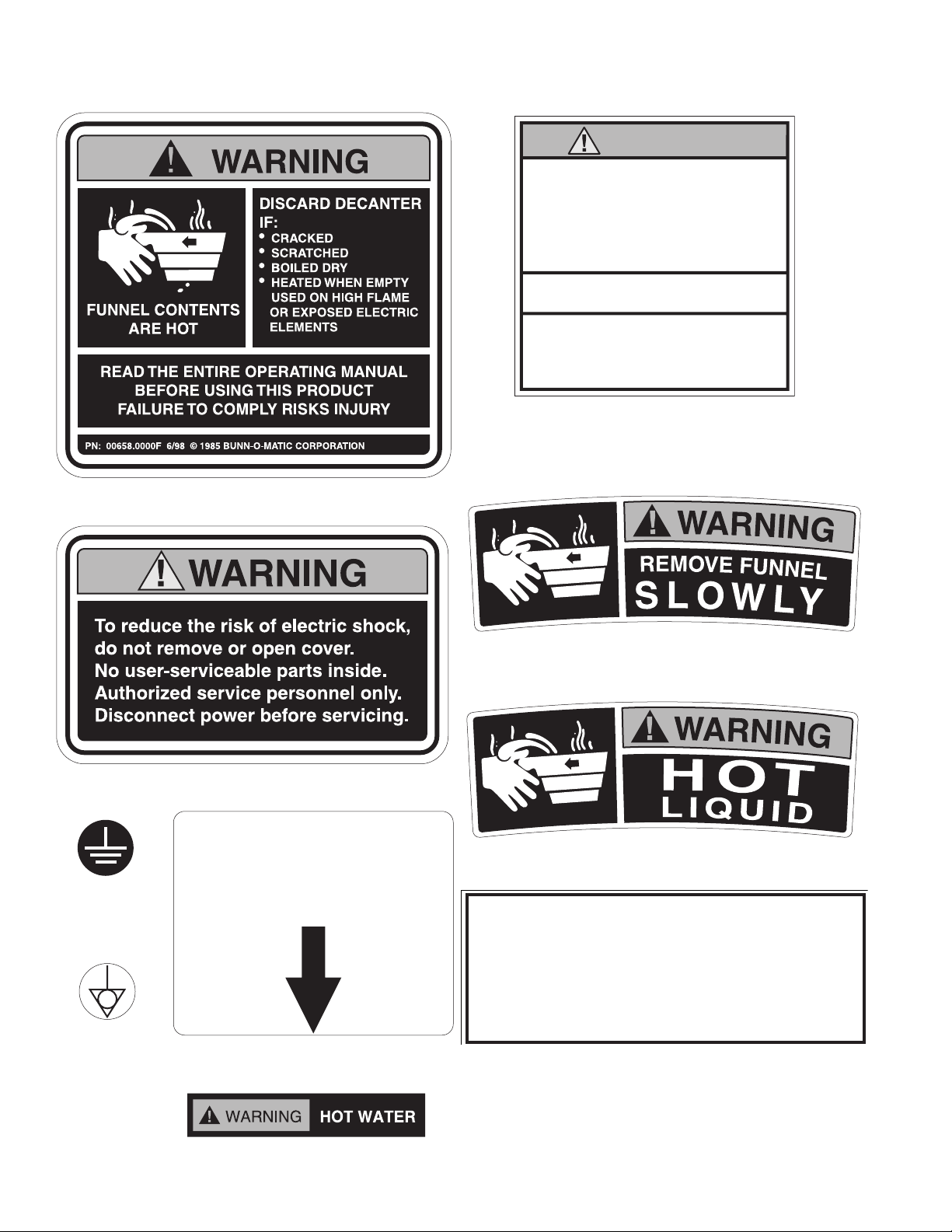
USER NOTICES
This equipment must be installed to comply
with the International Plumbing Code of the
International Code Council and the Food
Code Manual of the Food and Drug Administration (FDA). For models installed outside
the U.S.A., comply with the applicable
Plumbing /SanitationCode.
MAIN ON/OFF
SWITCH
WARNING
• DO NOT OVERLOAD CIRCUIT.
• ALWAYS ELECTRICALLY GROUND
THE CHASSIS.
• DO NOT DEFORM PLUG OR CORD.
• FOLLOW NATIONAL AND LOCAL
ELECTRICAL CODES.
• KEEP COMBUSTIBLES AWAY.
FAILURE TO COMPLY RISKS EQUIPMENT
DAMAGE, FIRE OR SHOCK HAZARD.
READ THE ENTIRE
OPERATING MANUAL BEFORE
USING THIS PRODUCT
00986.0000F 10/07 ©1994 Bunn-O-Matic Corporation
The notices on this brewer should be kept in good condition. Replace unreadable or damaged labels.
00986.0000
00658.0000
37881.0000
00824.0000
00824.0001
39803.0000
20201.5600
03408.0004
03409.0004
00656.0000
34025 022509
Page 4
Page 5
ELECTRICAL REQUIREMENTS
L2
L1
G
L2 RED
GREEN GREEN
L1 BLACK
L2 RED
L1 BLACK
L2
N
L1
G
L2 RED
WHITE
GREEN GREEN
NEUTRAL
L1 BLACK
L2 RED
WHITE
NEUTRAL
L1 BLACK
N
L1
G
WHITE
GREEN GREEN
NEUTRAL
L1 BLACK
WHITE
NEUTRAL
L1 BLACK
WARNING - The brewer must be disconnected from the power source until specified in Initial Set-Up.
Refer to Data Plate on the Brewer, and local/national electrical codes to determine circuit requirements.
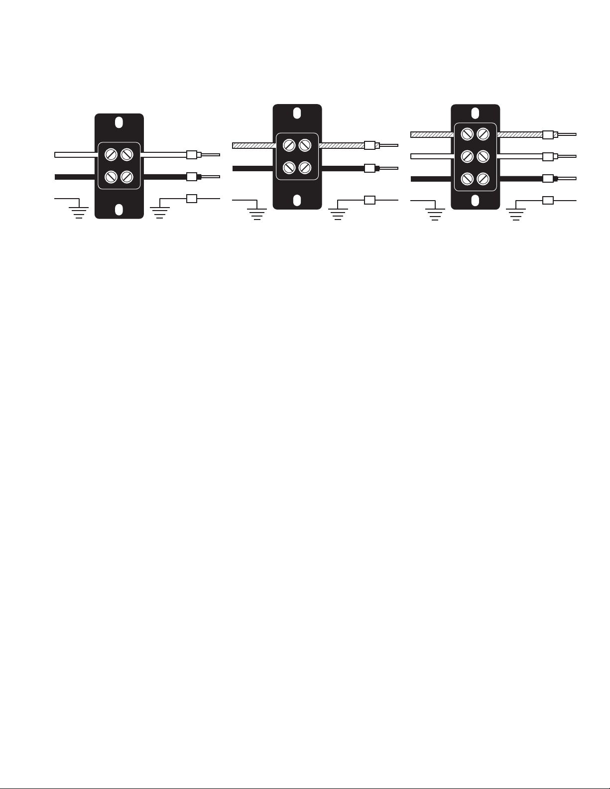
120 volt ac models
Note: This electrical service consists
of 2 current carrying conductors (L1
and Neutral) and a separate conductor for earth ground.
ELECTRICAL HOOK-UP (Models without power cord)
CAUTION – Improper electrical installation will damage electronic components. Damage caused by incorrect
electrical connections is not covered by warranty.
1. An electrician must provide electrical service as specified in conformance with all local, state and federal
electrical codes.
2. Using a voltmeter, check the voltage and color coding of each conductor at the electrical source.
3. Remove the front panel beneath the sprayheads to gain access to the terminal block.
4. Feed the cord through the strain relief and connect it to the terminal block.
5. Connect the brewer to the power source and verify the voltage at the terminal block before proceeding. Replace the front panel.
6. If plumbing is to be hooked up later be sure the brewer is disconnected from the power source. If plumbing
has been hooked up, the brewer is ready for Initial Set-Up.
ELECTRICAL HOOK-UP (Models with power cord)
WARNING– If the power cord is ever damaged, it must be replaced by the manufacturer or its service agent
with a special cord available from the manufacturer or its service agent in order to avoid a hazard. Improper
electrical installation will damage electronic components. Damage caused by incorrect electrical connec-
tions is not covered by warranty.
1. An electrician must provide electrical service as specified in conformance with all local, state and federal
electrical codes.
2. Using a voltmeter, check the voltage and color coding of each conductor at the electrical source.
NOTE - The brewer is shipped without a plug on the power cord. Qualified service personnel must select
and install the proper UL listed grounding type attachment plug specified on the rear of the brewer.
3. Install the specified plug on the attached power cord.
4. Remove the front panel beneath the sprayheads to gain access to the terminal block.
5. Connect the brewer to the power source and verify the voltage at the terminal block before proceeding.
6. If plumbing is to be hooked up later be sure the brewer is disconnected from the power source. If plumb-
WARNING – Electrical connections must be made as specified above. Failure to follow these instructions can
ing has been hooked up, the brewer is ready for Initial Set-Up.
result in personal injury, property or equipment damage.
200 and 230 volt ac models
Note: This electrical service consists
of 2 current carrying conductors (L1
and L2) and a separate conductor
for earth ground.
Page 5
120/208 & 120/240 volt ac models
Note: This electrical service consists
of 3 current carrying conductors
(Neutral, L1 and L2) and a separate
conductor for earth ground.
34025 022509
Page 6
CE REQUIREMENTS
• This appliance must be installed in locations where it can be overseen by trained personnel.
• For proper operation, this appliance must be installed where the temperature is between 5°C to 35°C.
• Appliance shall not be tilted more than 10° for safe operation.
• An electrician must provide electrical service as specied in conformance with all local and national codes.
• This appliance must not be cleaned by water jet.
• This appliance is not intended for use by persons (including children) with reduced physical, sensory or mental
capabilities, or lack of experience and knowledge, unless they have been given instructions concerning use of
this appliance by a person responsible for its safety.
• Children should be supervised to ensure they do not play with the appliance.
• If the power cord is ever damaged, it must be replaced by the manufacturer or authorized service personnel with
a special cord available from the manufacturer or its authorized service personnel in order to avoid a hazard.
PLUMBING REQUIREMENTS
This brewer must be connected to a cold water system with operating pressure between 20 and 90 psi (138
and 620 kPa) from a 1⁄2" or larger supply line. A shut-off valve should be installed in the line before the brewer.
Install a regulator in the line when pressure is greater than 90 psi (620 kPa) to reduce it to 50 psi (345 kPa). The
water inlet fitting is 1⁄4" flare or female quick connect.
NOTE: Bunn-O-Matic recommends 1⁄4" copper tubing for installations of less than 25 feet and 3⁄8" for more than 25
feet from the 1⁄2" water supply line. A tight coil of copper tubing in the water line will facilitate moving the brewer
to clean the counter top. Bunn-O-Matic does not recommend the use of a saddle valve to install the brewer. The
size and shape of the hole made in the supply line by this type of device may restrict water flow.
This equipment must be installed to comply with the International Plumbing Code of the International
Code Council and the Food Code Manual of the Food and Drug Administration (FDA). For models installed outside the U.S.A., you must comply with the applicable Plumbing/Sanitation Code for your area.
PLUMBING HOOK-UP
1. Flush the water line and securely attach it to the flare fitting located on bottom of brewer.
2. Turn on the water supply.
Page 6
34025 022509
Page 7
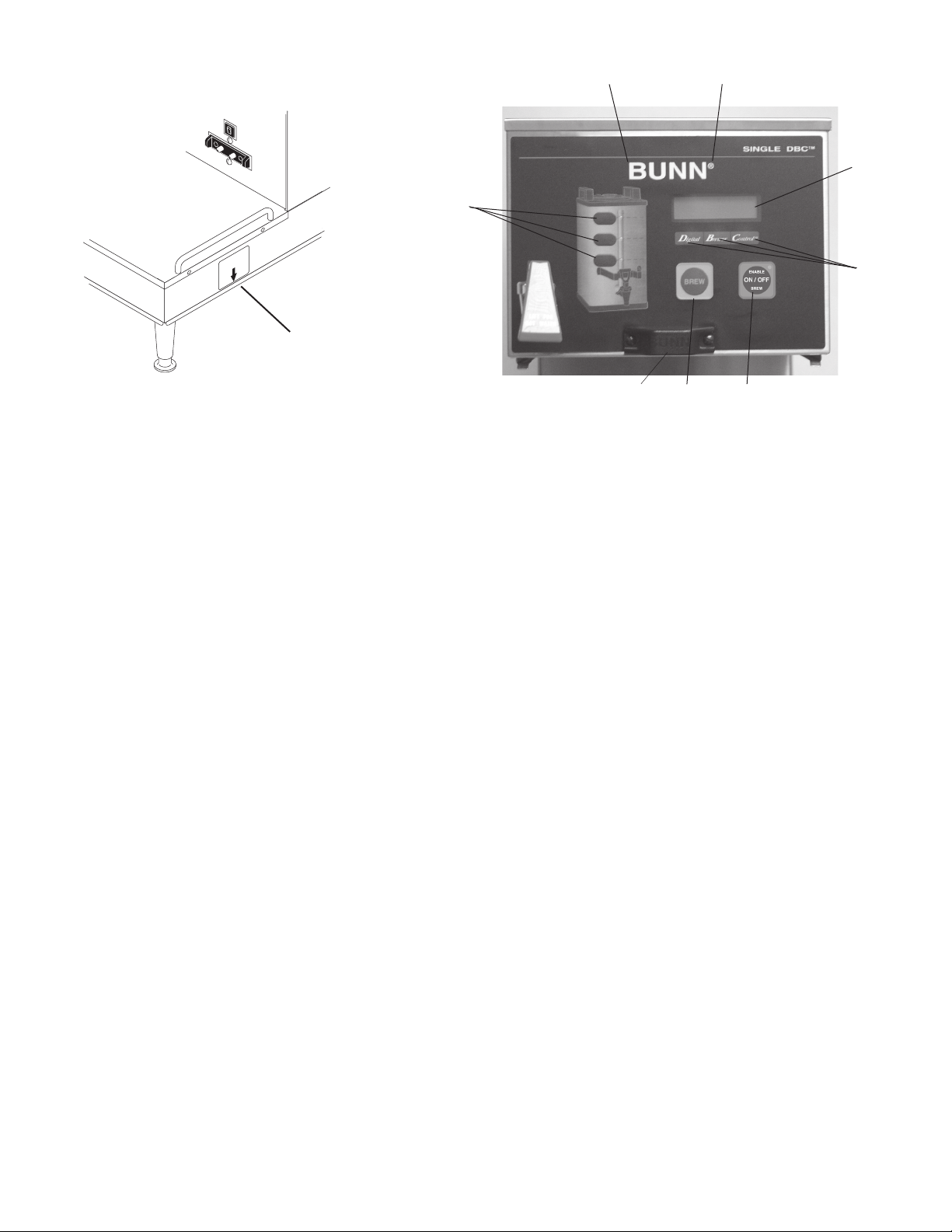
OPERATING CONTROLS
MAIN ON/OFF
SWITCH
j
e
f
b
g
a
P3853
h
d
c
P2437
OPERATING CONTROLS
(a) MAIN ON/OFF SWITCH
This switch, located under the brewer behind the right front leg, turns power on and off to all components
in the brewer.
(b) BATCH SELECTOR SWITCHES
Pressing the switch corresponding to the Small, Medium, or Large batch selects the amount of coffee to
be brewed. Pressing a different switch after a brew cycle has been initiated does not change the brew batch in
progress. Light indicates the selected batch to brew.
(c) ON/OFF SWITCH (ENABLE BREW)
Pressing the ON/OFF switch alternately turns the brewer on and off. Pressing this switch during the brew
cycle will interrupt the brew cycle, stopping the flow of water. Pressing this switch during the programming of
the brewer will exit the setup and return to the main screen.
(d) BREW SWITCH
Momentarily pressing and releasing this switch begins a brew cycle.
(e) PROGRAM SWITCH (Upper Right Hidden Switch)
Pressing and holding the upper right hidden switch allows entry to the programming menus. Pressing and
releasing the switch steps through each function screen during programming.
(f) FUNCTION SCREEN
This is the display which shows the various functions of the brewer and allows the programming to be accomplished.
(g) FUNCTION SCREEN SWITCHES
These are the hidden switches which are used to program the brewer.
(h) FUNNEL SENSING COIL
This is used to "receive" information from the Smart Funnel handle (coffee name and batch size), and also
from RECIPE CARDS.
(j) SCROLL BACKWARDS (Upper Left Hidden Switch)
The upper left corner of the B in BUNN can be used to scroll backwards through the function list.
34025 022509
Page 7
Page 8

INITIAL SETUP
CAUTION: The brewer must be disconnected from the power source throughout the initial setup, except when
specified in the instructions.
1. Insert an empty funnel into the funnel rails of the brew station.
2. Place an empty server under the funnel.
3. Connect the brewer to the power source. Water will begin flowing into the tank and stop when the tank is
filled to its capacity. Display will show PLEASE WAIT...TANK FILLING until tank is filled with water.
4. Wait approximately twenty minutes for the water in the tank to heat to the proper temperature. Display will
show READY TO BREW...WATER TEMP: XXX˚ when tank is at operating temperature.
5. Place a small vessel beneath the faucet and open the faucet handle. Release it when you hear the tank refilling.
6. Water volumes have been preset at the factory. Refer to adjustments for the Set Brew Volumes section of
this manual should the volume need to be increased or decreased.
7. The brewer is now ready for use in accordance with the coffee brewing instructions.
COFFEE BREWING
1. Insert a BUNN filter into the Smart Funnel.
2. If a grinder is not used to obtain the coffee grounds, pour the proper amount of fresh coffee grounds into
the funnel and level by gently shaking. Slide the funnel into the funnel rails and select batch size. Proceed to
step 5.
3. If a G9-2T DBC or MHG grinder is used with a compatible Smart Funnel, select the desired batch size on the
grinder. Grind the selected amount of fresh coffee into funnel and level grounds by gently shaking. It is not
necessary to select a size on the brewer.
4. Slide the funnel into the funnel rails. The brewer will read the size ground through the chip in the funnel
handle and will automatically select the correct size to brew.
5. Place an empty server under the funnel.
6. The ENABLE BREW switch must be ON. Momentarily press and release the "BREW" switch. If the brewer has
the funnel lock option and if it is activated, once a brew cycle has been started the funnel is locked in place.
There may be certain situations in which the brew cycle will not begin when the brew switch is pressed:
a) BREW TEMPERATURE TOO LOW - wait until heated or cancel BREW LOCKOUT option.
b) FUNNEL NOT IN PLACE (or using a standard brew funnel) - cancel FUNNEL DETECT option.
c) CHECK FUNNEL - remove funnel, empty previously brewed grounds and grind a new batch into funnel.
d) SERVER NOT IN PLACE - place Soft Heat Server, or cancel SERVER DETECT option.
7. If none of the above messages are displayed, the display will read NOW BREWING and the time remaining
in the brew cycle. Arrows will point to the side which is brewing. If both sides are brewing simultaneously,
the arrows will alternate from left to right on the display.
8. Following the BREW will be a countdown of DRIPPING time which shows the time remaining until the funnel
lock will release. Discard the grounds and filter only after visible dripping stops.
CLEANING
1. The use of a damp cloth rinsed in any mild, nonabrasive, liquid detergent is recommended for cleaning all
surfaces on Bunn-O-Matic equipment.
2. Check and clean the sprayhead. Use the pointed end of sprayhead cleaning tool (#38227.0000) to remove
any mineral deposits from the sprayhead holes.
3. Insert the long end of sprayhead cleaning tool into the sprayhead fitting, and rotate several times to remove
any mineral deposits from the fitting.
4. Insert the short end of sprayhead cleaning tool into the bypass fitting, and rotate several times to remove
any mineral deposits from the fitting.
NOTE: In hard water areas, this may need to be done daily. It will help prevent liming problems in the brewer
and takes less than a minute.
Page 8
34025 022509
Page 9

GLOSSARY
AD CARD: An assembly consisting of a computer chip and an instruction label. Used for loading advertising
messages into the brewer.
BREW LOCKOUT: The inability to initiate a brew if the water temperature is less than the ready temperature
programmed into the brewer.
BYPASS: The process of diverting a portion of the brew water to the outside of the paper filter so that it does
not pass through the coffee grounds. This process is sometimes used to optimize the flavor of the finished
brew.
CHIP: A computer chip containing either recipes for specific coffee flavors or advertising messages which are
read by the sensing coils on the brewer. One chip is embedded in each Smart Funnel handle to carry the
coffee flavor name and batch size ground from the grinder to the brewer.
DRIP TIME: The length of time from when the water spray over the grounds ends, to the time that no water drips
from the funnel tip.
FACTORY DEFAULTS: The factory preset brew settings that were installed into the brewer's memory.
FIRST ON-TIME: During a pulse brew, this is the time set for the initial flow of water over the grounds.
FUNNEL DETECT: Sets the inability to initiate a brew cycle if the funnel is not properly inserted into the funnel
rails.
FUNNEL SENSING COIL: A sensor on the front hood of the brewer, which reads what name and batch size of
coffee was ground into the funnel and allows for the brewer to automatically set itself to what is read from
the funnel handle.
LAST ON-TIME: During a pulse brew, this is the time set for the second on-time, and each alternating on-time
for the remainder of the brew cycle.
MAIN SCREEN: The term used to describe the screen that is displayed when the brewer is not in use. This screen
is also displayed after exiting the programming mode.
NO-NAME COFFEE: The term for the recipe used by the brewer when there is no coffee name stored in the fun-
nel.
OFF-TIME: During a pulse brew or preinfusion, this is the time set for the length of time that the water is not
spraying over the grounds.
PREINFUSION: The process of beginning a brewing cycle with an initial spray of water onto the grounds followed
by a pause in the spray. After the programmed pause, the spray continues without interruption until the
end of the brewing cycle.
PULSE BREW: The process which allows the brew water to start, then stop, repeatedly, over the grounds in order
to derive the best flavor from the coffee. Pulse brew is also used in some instances to prevent a funnel
overflow.
RECIPE: Set of brewing parameters stored in the brewer. The parameters are unique for each coffee name and
include brew ounces, pulse brew, percent bypass, preinfusion and drip time.
RECIPE CARD: An assembly consisting of a computer chip and an instruction label. Used for loading a recipe
into the brewer and the companion BrewWISE Grinder.
SERVER DETECT: Sets the inability to initiate a brew cycle if the server is not properly placed on the stand below
the brew funnel.
®
SOFT HEAT
is placed on the brewer, and is connected through the receptacles on the brewer. The server contains a
temperature-controlled heater which maintains the coffee at a constant temperature.
: The type of server and brewer which are used as part of the Smart Funnel system. The server
Page 9
34025 012004
Page 10
PROGRAMMING
READY TO BREW
WATER TEMP: 200°
Using the menu-driven display on the front of the brewer, the operator has the ability to alter or modify various
brewing parameters such as brew temperatures, brew volumes, bypass percentages, etc. This allows for the
precise brewing of various flavors of coffee.
Programming of the brewer is achieved by entering a certain function. Then, by the use of hidden programming
switches, the operator can customize the brewing process to their specifications.
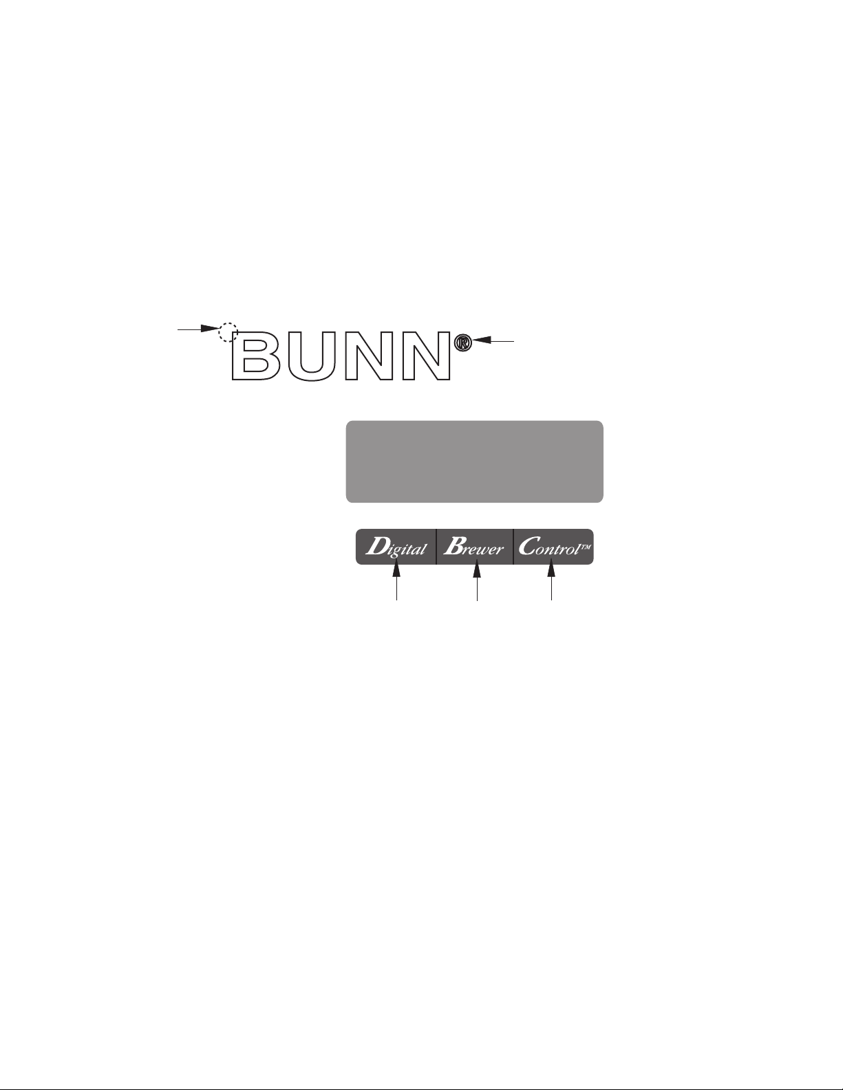
PROGRAMMING SWITCHES
To access the programming mode, and to scroll through the different function screens, hidden programming
switches are used. There are five of these switches that will be used for the setup of the brewer.
2
3 4 5
1. ® symbol (upper right of the BUNN logo)
This is used to access the programming mode and is also used to scroll forward through the function list.
1
P2450
2. Upper left corner of the "B" in the BUNN logo
This is used to scroll backwards through the function list.
3. "Digital" (lower left under the display)
This is used to select options that appear on the display during programming.
4. "Brewer" (center under the display)
This is used to select options that appear on the display during programming.
5. "Control" (lower right under the display)
This is used to select options that appear on the display during programming.
Page 10
34025 100501
Page 11
PROGRAMMING THE BREWER
PROGRAM
ENABLE
DISABLE
The programming of the brewer is divided into two levels. There is one function in Level 1. All other functions
are accessed in Level 2.
The following function screens are in order of appearance. Each screen will have instructions on how to
access, and the procedures to program the various functions of the brewer.
IMPORTANT PROGRAMMING NOTES
- READ CAREFULLY -
To exit the programming mode at any time, press and release the pad located on the front switch panel.
The display will return to the MAIN SCREEN.
If none of the five programming switches are pressed within one minute during the setup of the brewer,
the programming of the function screen that is being set will be exited and the display will return to the MAIN
SCREEN.
Always remember to place a container and funnel under the sprayhead when operating the brewer during
the set-up of PULSE BREW - SET BY EXAMPLE, CALIBRATE FLOW and testing the brew and bypass valves in
SERVICE TOOLS/TEST OUTPUTS.
MAIN SCREEN
READY TO BREW
WATER TEMP: 200°
This screen will be shown when the brewer is ready
for use. The screen displays the water temperature
in the tank. When the water in the tank reaches the
correct set temperature, the display will change from
HEATING to READY TO BREW.
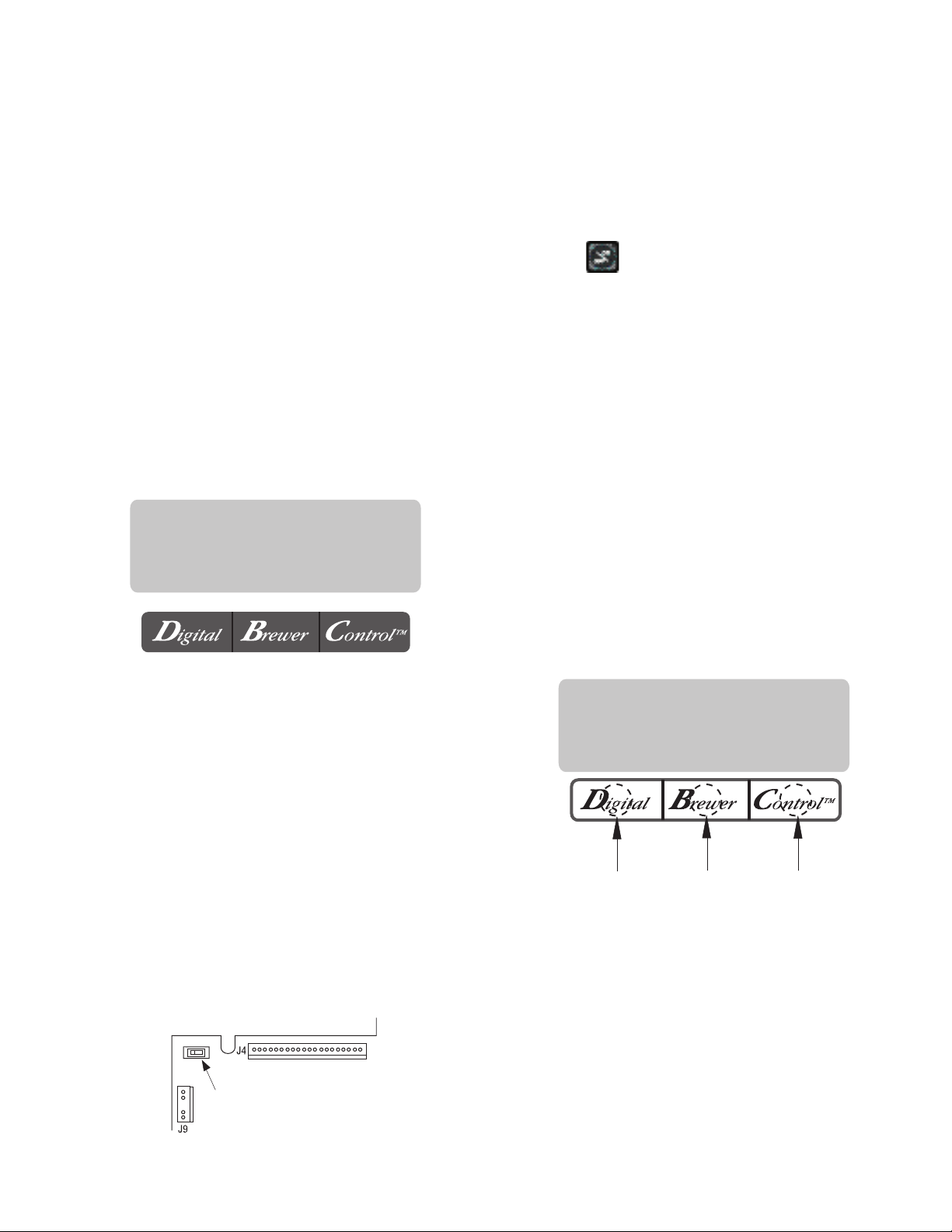
PROGRAMMING LOCKOUT SWITCH (mounted on
main control board)
This switch can be set to prevent access to the
programming levels of the brewer. Once all the correct brew settings are programmed, the operator can
set the switch to the "DISABLE" position to prohibit
anyone from changing the settings.
PROGRAMMING
SWITCH
P2424
Page 11
PROGRAM FUNCTIONS - LEVEL 1
BREW LOCKOUT
This function allows the operator to prevent or
allow brewing if the water temperature is less than
the set READY temperature.
To access this function screen press and hold the
® symbol. Release the ® when the display reads:
BREW LOCKOUT?
NO DONE YES
Press here
for NO
Press here
for DONE
The YES or NO should be flashing. Select YES to
prevent brewing if the water temperature is below the
set READY temperature. Select NO to permit brewing
at any water temperature.
When finished, press and release DONE. This
will exit this function screen and return to the MAIN
SCREEN on the display.
Press here
for YES
34025 022509
Page 12
PROGRAMMING THE BREWER (cont.)
ARE YOU CREATING OR CHANGING A RECIPE FOR A
COFFEE NAME PREVIOUSLY USED IN THIS BREWER?
REFER TO NAME LIST
IN GRINDER MANUAL
CONTACT BUNN-O-MATIC
FOR ASSISTANCE
GO TO REVIEW RECIPES
AND FOLLOW INSTRUCTIONS
TO VIEW A LIST OF EXISTING RECIPES,
GO TO REVIEW RECIPES
AND FOLLOW THE INSTRUCTIONS
GO TO SET NEW RECIPE
AND FOLLOW THE
INSTRUCTIONS
YOU WILL ENTER
THE NO NAME
BREW SETTINGS
YOU WILL MODIFY AN
EXISTING RECIPE
DOES THE GRINDER HAVE THE
NAME IN ITS MEMORY?
FOLLOW INSTRUCTIONS
ON THE RECIPE CARD
HAVE YOU RECEIVED A RECIPE CARD
CONTAINING THE NEW RECIPE?
OR
OR
NO
NO
DON'T KNOW
NO
YES
YES
YES
DON'T
KNOW
PROGRAM FUNCTIONS - LEVEL 2
There are three methods of programming the
various brewing parameters of the SINGLE SH with
®
Smart Funnel
Brewer.
METHOD 1:
Using a Smart Funnel and a G92T DBC Grinder:
Certain coffee NAMES are stored in the G92T
DBC's memory. When a particular name of coffee is
ground into the Smart Funnel, that name and the batch
size selected are transferred from the grinder to the
programming chip located in the funnel's handle. The
funnel is then inserted into the brewer's funnel rails.
The sensor coil on the brewer reads the information
contained in the handle. This then allows the operator
to set the BREW VOLUMES, BYPASS PERCENTAGES,
PULSE BREW TIMES, PREINFUSION TIMES and
DRIP-OUT TIMES for that particular coffee NAME.
Each coffee NAME can be set individually to provide
optimum brewing quality.
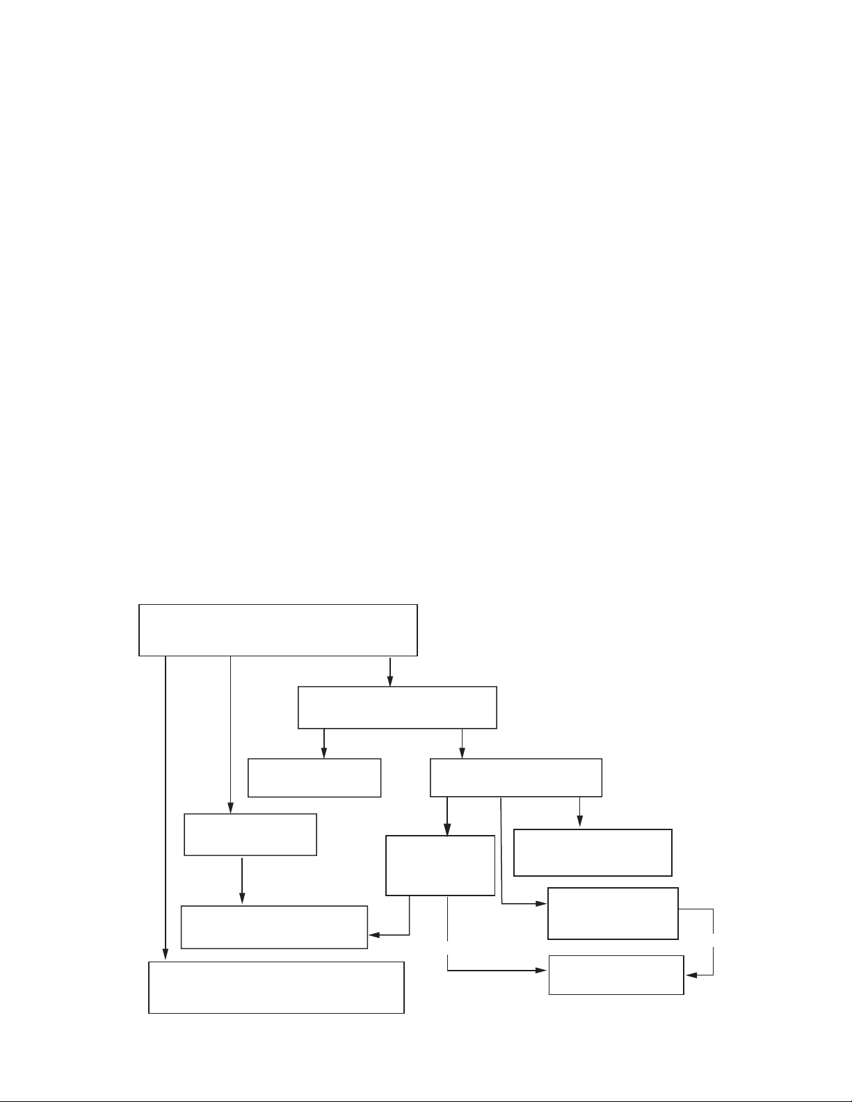
RECIPES
This diagram allows for the creating, modifying,
or viewing of recipes in the brewer.
METHOD 2:
Using a RECIPE CARD to enter all of the brew settings at one time:
If using a coffee flavor not in the G92T DBC's
memory, the customer can obtain a RECIPE CARD
from the factory with all the information needed to set
up that particular coffee flavor. This includes the name
of the coffee, BREW VOLUMES, BYPASS PERCENT-
AGES, PULSE BREW TIMES, PREINFUSION TIMES,
and DRIP-OUT TIMES.
METHOD 3:
Not using a Smart Funnel and/or a G92T DBC
Grinder:
This allows the operator to enter ONE set of brew-
ing parameters in the event a Smart Funnel and/or a
G92T DBC is not used with the SINGLE SH Brewer.
This is referred to as a NO NAME coffee flavor. If the
brewer does not read the information in the funnel
handle, it automatically selects the NO NAME brewing
parameters set up prior to brewing. This includes the
BREW VOLUMES, BYPASS PERCENTAGES, PULSE
BREW TIMES, PREINFUSION TIMES and DRIP-OUT
TIMES for the three batch sizes.
Page 12
P2438
34025 012004
Page 13
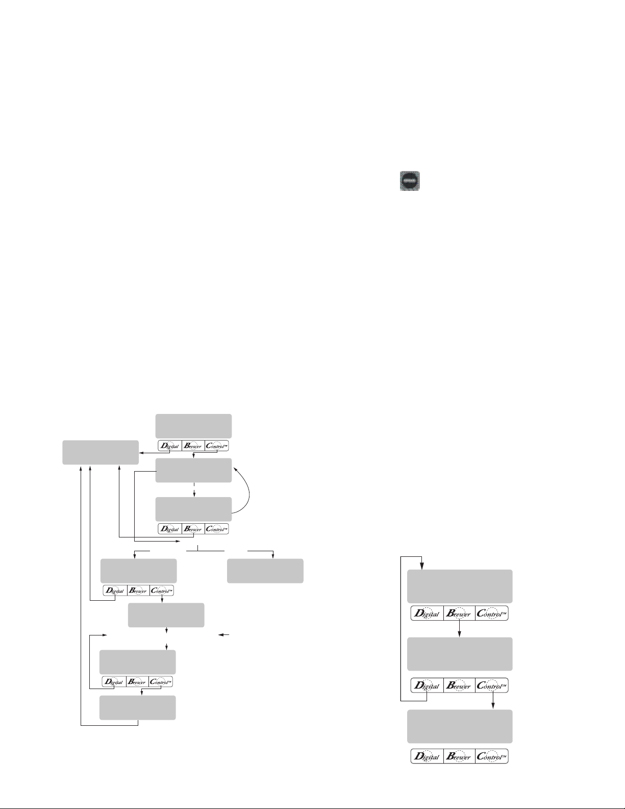
MUST GRIND INTO
FUNNEL FIRST
(COFFEE NAME)
SETUP COMPLETE
BEGIN SETUP OF
(COFFEE NAME)
QUIT SETUP?
YES
INSERT FUNNEL
WITH NEW NAME
REVIEW RECIPES?
NO YES
(COFFEE NAME)
NO YES
3 BATCHES DONE?
NO YES
SET NEW RECIPE?
NO YES
2 SEC.
CYCLES THROUGH
TWO SCREENS
FUNNEL
CONTAINS NAME
FUNNEL CONTAINS
NO NAME
SETUP BREW VOLUMES, BYPASS, PULSE BREW,
PREINFUSION, DRIPOUT TIME
SEE SEPARATE DIAGRAMS
FOR SETUP INSTRUCTIONS
FUNNEL DETECTED
PROGRAMMING FUNCTIONS - LEVEL 2 (cont.)
BREW OZ. XX.X
(-) DONE (+)
% BYPASS XX.X
(-) DONE (+)
3 BATCHES DONE?
NO YES
SET NEW RECIPE
Using a Smart Funnel and a G92T DBC Grinder:
This function allows the operator to set BREW VOLUMES, BYPASS PERCENTAGES, PULSE BREW TIMES,
PREINFUSION TIMES and DRIP-OUT TIMES for each
coffee name preset in the grinder's memory.
Certain coffee NAMES are stored in the G92T
DBC's memory. When a particular name of coffee is
ground into the Smart Funnel, that name and the batch
size selected are transferred from the grinder to the
programming chip located in the funnel handle. The
funnel is then inserted into the brewer's left side funnel
rails. The sensor coil on the brewer reads the information contained in the handle. The name of the coffee
flavor will then appear on the display. This then allows
the operator to set the BREW VOLUMES, BYPASS
PERCENTAGES, PULSE BREW TIMES, PREINFUSION
TIMES and DRIP-OUT TIMES for that particular coffee
NAME. It also allows the operator to set other brewing
parameters, such as BREW TEMPERATURE, READY
TEMPERATURE, BREW LOCKOUTS, etc. Each coffee
NAME can be set individually to provide optimum
brewing quality.
Procedure for Setting the Recipe:
NOTE: Before beginning setup, place a server beneath
the sprayhead.
1. Insert the funnel into the grinder and select a batch
size to grind. It is not necessary to have coffee beans
in the hopper(s) in order to program the brewer.
The coffee name is pre-selected and stored in the
grinder's memory for the side being ground.
2. Press the
pad. When the grinder stops grind-
ing, remove the funnel.
3. On the brewer, press and hold the ® pad until the
display reads SET NEW RECIPE. Release the ®
pad.
4. Press and release YES. The display should read
INSERT FUNNEL WITH NEW NAME, then QUIT
SETUP? These two displays will repeatedly
cycle.
5. Insert the funnel into the rails of the brewer. The
display should read the NAME of the coffee that
was ground into the funnel, along with a NO and
YES. If the NAME on the display is correct, press
YES.
6. If, for some reason, the name of the coffee from
the grinder did not load properly into the funnel,
or if a grind has not yet been done, the display will
read MUST GRIND INTO FUNNEL FIRST. It will be
necessary to grind another batch following steps
1 and 2.
7. If the grind is acknowledged by the brewer, the
display will read BEGIN SETUP OF (COFFEE
NAME). Then the screen will display BREW OZ.
and a batch light will be blinking. (Refer to page
19 for description of BREW OZ. function).
P2439
P2415
34025 022509
Page 13
Page 14
PROGRAMMING FUNCTIONS - LEVEL 2 (cont.)
% BYPASS XX.X
(-) DONE (+)
3 BATCHES DONE?
NO YES
SET PULSE BREW?
NO YES
ON TIME X:XX
(-) DONE (+)
OFF TIME X:XX
(-) DONE (+)
ON OFF
X:XX X:XX
DRIP TIME X:XX
(-) DONE (+)
3 BATCHES DONE?
NO YES
SET PREINFUSION?
NO YES
ADVANCES
TO NEXT
FUNCTION
5 SEC. DELAY
SET NEW RECIPES (cont.)
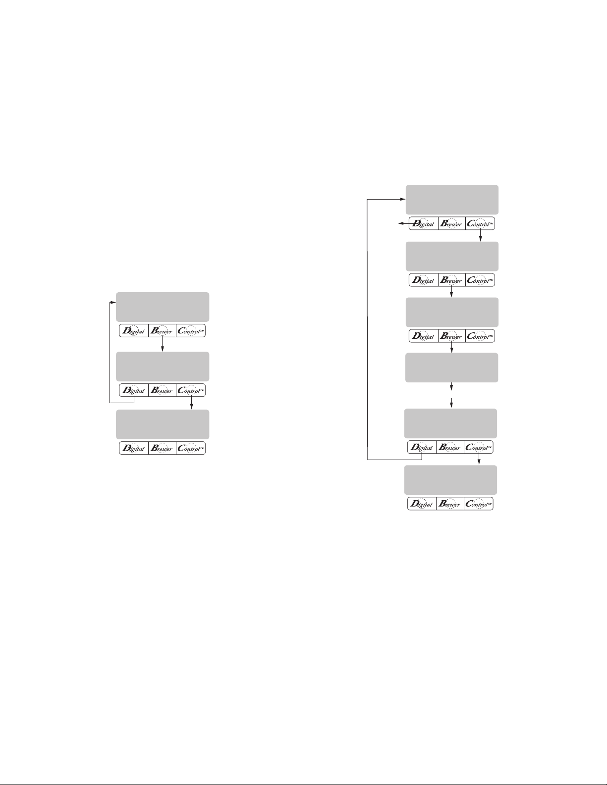
8. Using (-) and (+), set the amount of brew water,
in ounces, to be dispensed over the grounds for
that particular batch size.
9. When finished, press another batch size and repeat
step #8 for that size. Continue setting all batch
sizes.
10. When finished setting all batch sizes, press and
release DONE. The display should read 3 BATCH
SIZES DONE?
11. If the three batch sizes are not correct, press
and release NO to return to the BREW OUNCES
setup screen and repeat steps 8 through 10. If
the three batch sizes are correct, press YES. This
will advance to the % BYPASS function. (Refer to
page 20 for description of % BYPASS function.)
17. If setting pulse brew by ENTER TIMES (entering
known times) press NO. The display should read
ENTER TIMES. Press and release YES and proceed
with the setup instructions for SETTING PULSE
BREW - ENTER TIMES, page 24. After SET PULSE
BREW has been accomplished, the next function
will be SET PREINFUSION. (Refer to page 25 for
description of SET PREINFUSION function.
12. Using (-) and (+) set the amount of bypass water
(percentage) to be dispensed around the grounds
for that particular batch size.
13. When finished, press another batch size and repeat
step #12 for each batch to be set.
14. When finished setting each batch size, press
DONE. The display should read 3 BATCHES
DONE?
15. If the three batch sizes are not correct, press and
release NO to return to the % BYPASS setup screen
and repeat steps 12 through 15. If they are correct, press YES. This will advance to SET PULSE
BREW. (Refer to page 21 for description of SET
PULSE BREW function.
16. To SET PULSE BREW, if setting pulse brew BY
EXAMPLE (brewing into a funnel) press YES and
proceed with the setup instructions for SETTING
PULSE BREW - BY EXAMPLE, on page 23.
P2416
P2417
18. To SET PREINFUSION press YES in the SET PRE-
INFUSION screen to proceed. The display should
now read ON TIME and a batch light will be blink-
ing.
19. Using (-) and (+), set the amount of time the brew
water will initially presoak the grounds for that
particular batch size.
20. When finished, press another batch size and repeat
until all three batch sizes are set.
21. When finished, press DONE. The display should
now read OFF TIME and a batch light will be blink-
ing.
Page 14
34025 022509
Page 15
(COFFEE NAME)
SETUP COMPLETE
DRIP TIME X:XX
(-) DONE (+)
3 BATCHES DONE?
NO YES
PROGRAMMING FUNCTIONS - LEVEL 2 (cont.)
SET NEW RECIPES (cont.)
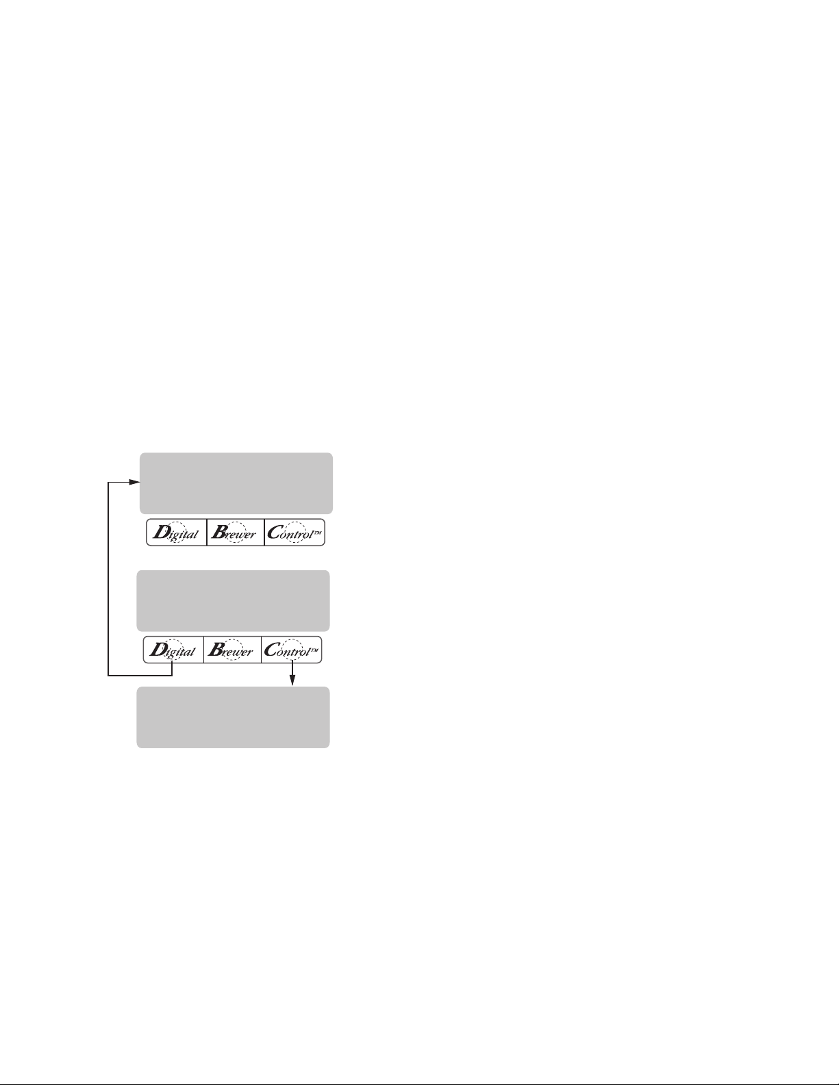
22. Using (-) and (+), set the amount of time the brew
cycle will delay (after the presoak cycle shuts off)
before resuming brewing.
23. When finished, press another batch size and repeat
until all three batch sizes are set.
24. When finished setting all batch sizes, press DONE.
The display will show the ON and OFF TIMES that
were entered for a particular batch size. After a 5
second delay, the display should read 3 BATCHES
DONE.
25. If the three batches are not complete, press NO in
order to return to SET PREINFUSION, and repeat
steps 19 through 24.
26. If the three batches are correct, press YES. This
will advance to the next function, SET DRIP TIME.
(Refer to page 26 for description of SET DRIP
TIME function.)
27. The display should now read DRIP TIME, along
with either the word OFF, or a time will be showing.
A batch light should also be blinking.
28. Using (-) and (+), set the amount of time from
when the brew spray ends to when the funnel is
emptied of hot liquid for that batch size.
NOTE: Set to OFF to prevent funnel locks from engaging
(to disable this function), for a particular batch size.
To set to OFF, continue to press and release (-) until
OFF appears on the screen.
29. When finished, press another batch size and repeat
step 28 until all three sizes are set.
30. When finished setting all batch sizes press DONE.
The display should read 3 BATCHES DONE?.
31. If the three batch sizes are not correct, press NO to
return to the DRIP TIME setup screen and repeat
steps 28 through 30.
32. If the three batch sizes are correct, press YES.
The screen should show the name of the coffee
being programmed (modified) along with SETUP
COMPLETE.
32. After a 5 second delay, the display will advance to
the next coffee name in the brewer's memory. If
no other coffee names are present, the display will
read THAT WAS THE LAST RECIPE, and return to
the REVIEW RECIPES screen.
P2418
34025 022509
Page 15
Page 16
PROGRAMMING FUNCTIONS - LEVEL 2 (cont.)
POSITION CARD UNDER
SENSOR COIL
(COFFEE NAME)
SHOW QUIT SAVE
CARD CONTAINS
RECIPE FOR
READY TO BREW
WATER TEMP: 200º
(COFFEE NAME)
SETUP COMPLETE
(COFFEE NAME)
NOT SAVED
SCROLLS THROUGH ALL
OF THE BREW SETTINGS
FOR THE THREE BATCH
SIZES FOR THAT COFFEE
NAME
SET NEW RECIPE
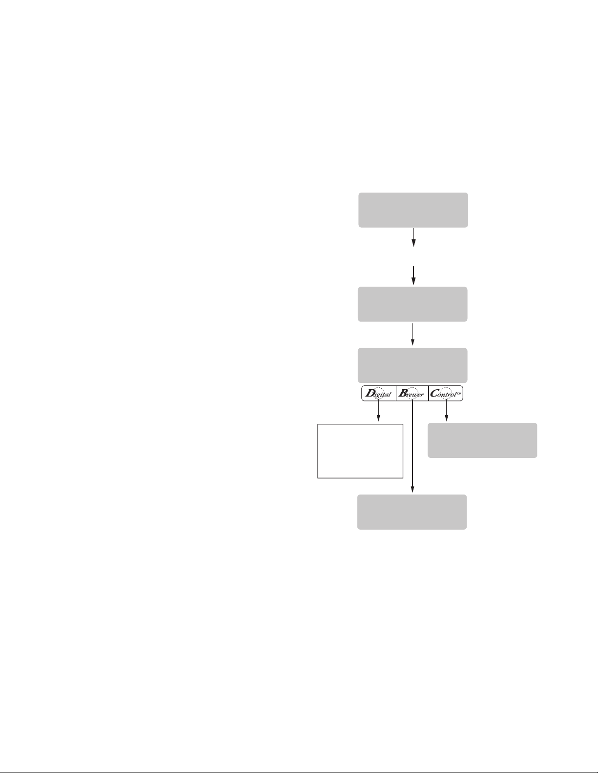
Using a RECIPE CARD to load coffee names and
brew settings into the SINGLE SH DBC with Smart
Funnel
The G92T DBC's memory contains certain coffee
names. If the operator uses a coffee name that is not
already stored in the grinder's memory, a RECIPE
CARD can be obtained from the factory. The RECIPE
CARD would include all the information needed to
set up that particular coffee name. The information
from the RECIPE CARD is loaded into the grinder's
memory, then into the brewer's memory by holding
the recipe card up to the equipment's sensing coil.
This information can include the coffee name, BREW
VOLUMES, BYPASS PERCENTAGES, PULSE BREW
TIMES, PREINFUSION TIMES and DRIP-OUT TIMES
for that particular coffee NAME. These can all be loaded
in seconds.
Contact Bunn-O-Matic Corporation for the availability of RECIPE CARDS.
®
:
PLETE. All brew settings for that name are now
stored in the brewer's memory.
6. If the brewing information is not correct, or it is
desired to exit the setup before the settings are
loaded into the brewer's memory, press QUIT. The
display will read (COFFEE NAME) NOT SAVED. The
display will then return to the MAIN SCREEN.
NOTE: Instructions to program the brewer and grinder
are printed on the RECIPE CARD, along with the coffee
name that is being programmed.
Procedure to program the coffee name:
1. Remove the funnel (if present) from the funnel
rails.
2. Position the RECIPE CARD vertically, so that the
top end of the chip is beneath the funnel sensing
coil.
3. After a short pause the display will read CARD CON-
TAINS RECIPE FOR then will change to (COFFEE
NAME) SHOW QUIT SAVE. All brewing parameters
for that coffee flavor are now transferred from the
CARD to the brewer.
4. To show (view) this information, press and release
SHOW. The display will scroll through all of the
brew settings for all three batch sizes. The display
will then return to CARD CONTAINS RECIPE FOR
then will change to (COFFEE NAME) SHOW QUIT
SAVE.
5. If all brew settings are correct, press SAVE. The
display will read (COFFEE NAME) SETUP COM-
P2440
Page 16
34025 022509
Page 17
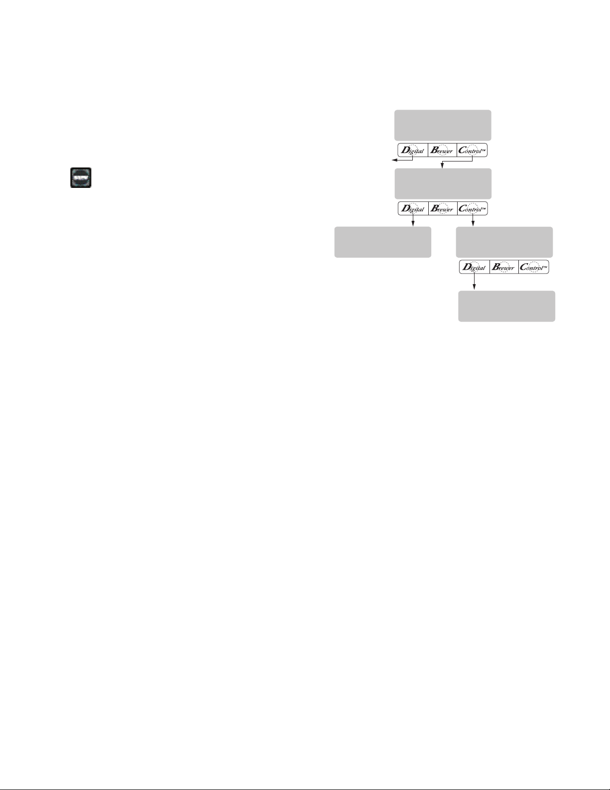
PROGRAMMING FUNCTIONS - LEVEL 2 (cont.)
REVIEW RECIPES?
NO YES
(COFFEE NAME)
MODIFYSHOWNEXT
BREW OZ. XX.X
(-) DONE (+)
BREW OZ. XX.X
(-) DONE (+)
NO-NAME
MODIFYSHOWNEXT
EXIT TO
NEXT FUNCTION
SCREEN
SET NEW RECIPE:
If not using a Smart Funnel (with a sensor coil) and/
or a G92T DBC Grinder, the brewer will function as
a standard BUNN Single Brewer:
It is possible to operate the brewer without using a
Smart Funnel and/or a G92T DBC Grinder. If a standard
funnel, or if a non-DBC grinder is used the brewer will
automatically select a NO NAME coffee flavor when
the
pad is pressed. This means that no name was
read from the funnel's handle.
There is a NO NAME coffee program that can be
set in the brewer. This includes BREW VOLUMES,
BYPASS PERCENTAGES, PULSE BREW TIMES, PREINFUSION TIMES and DRIP-OUT TIMES. The brewer
will perform in the same capacity as a standard BUNN
TM
Single
Brewer.
The instructions for programming the NO NAME
settings are on the following pages. The same steps
are followed for setting the recipe as those that are
used to MODIFY A RECIPE, beginning on page 19.
Note that when the display reads NO NAME, that
is when MODIFY should be pressed in order to set the
parameters for the NO NAME coffee.
NOTE: Before beginning setup, insert a funnel into
the funnel rails, and place a Soft Heat Server beneath
the brew funnel.
P2441
Page 17
34025 022509
Page 18
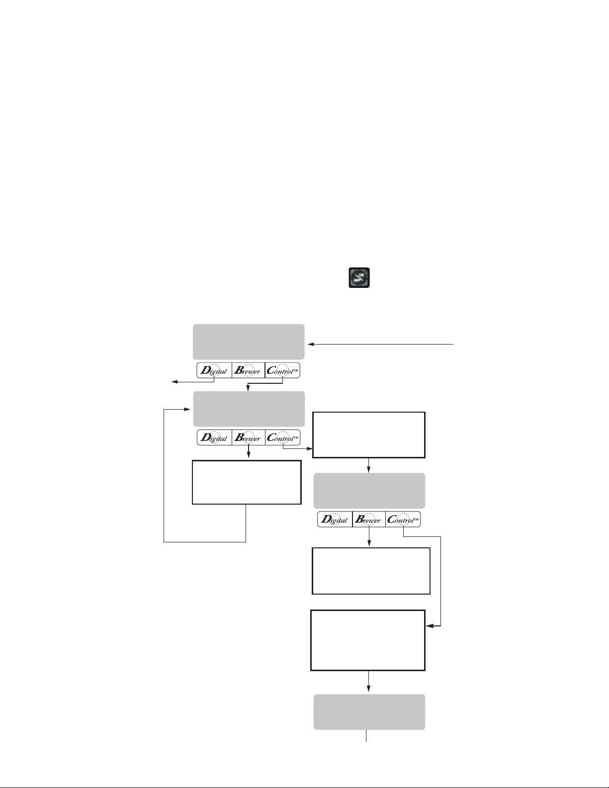
PROGRAMMING FUNCTIONS - LEVEL 2 (cont.)
(COFFEE NAME)
MODIFYSHOWNEXT
THAT WAS THE
LAST RECIPE
NO-NAME
MODIFYSHOWNEXT
REVIEW RECIPES?
NO YES
EXIT TO
NEXT FUNCTION
SCREEN
SCROLLS THROUGH ALL
BREW SETTINGS FOR
NO-NAME COFFEE
SCROLLS THROUGH ALL
BREW SETTINGS FOR ANY
OTHER OFFEE NAMES
STORED IN BREWER'S MEMORY
WHEN THE LAST COFFEE NAME
IN THE BREWER'S MEMORY IS
DISPLAYED, PRESSING NEXT
WILL EXIT AND THE DISPLAY
WILL THEN READ:
ADVANCES TO ALL OTHER
COFFEE NAMES PROGRAMMED
IN THE BREWER'S MEMORY
REVIEW RECIPES/MODIFY RECIPES/SET UP NO
NAME COFFEE FLAVORS:
This function has three parts. It allows the operator
to view the brew settings for the various coffee names
programmed into the brewer.
It also allows the operator to modify (change) any of
the BREW VOLUMES, BYPASS PERCENTAGES, PULSE
BREW TIMES, PRE-INFUSION TIMES and DRIP-OUT
TIMES for a particular coffee name programmed into
the brewer.
Finally, this function is used to set up the NO NAME
coffee BREW VOLUMES, BYPASS PERCENTAGES,
PULSE BREW TIMES, PRE-INFUSION TIMES and
DRIP-OUT TIMES.
Procedure for reviewing recipes:
1. Press and hold the ® pad until the display reads
SET NEW RECIPES. Release the ®. Press the ®
until the display reads REVIEW RECIPES.
2. Press YES to proceed. The display should now
read NO NAME, along with MODIFY, SHOW and
NEXT.
3. Press and release SHOW. The screen will scroll
through all the brew settings for that particular
coffee flavor name. When finished, the display
will return to the coffee name just viewed.
4. To see settings again, press SHOW. To advance
to the next coffee flavor name, press NEXT.
5. To exit, press NEXT until the display reads THAT
WAS THE LAST RECIPE.
6. After 5 seconds, the display will return to the
REVIEW RECIPES screen. Press and release NO
to advance to the next function screen, or press
the
pad located on the front switch panel
to exit the programming mode and return to the
MAIN SCREEN.
P2442
Page 18
34025 022509
Page 19
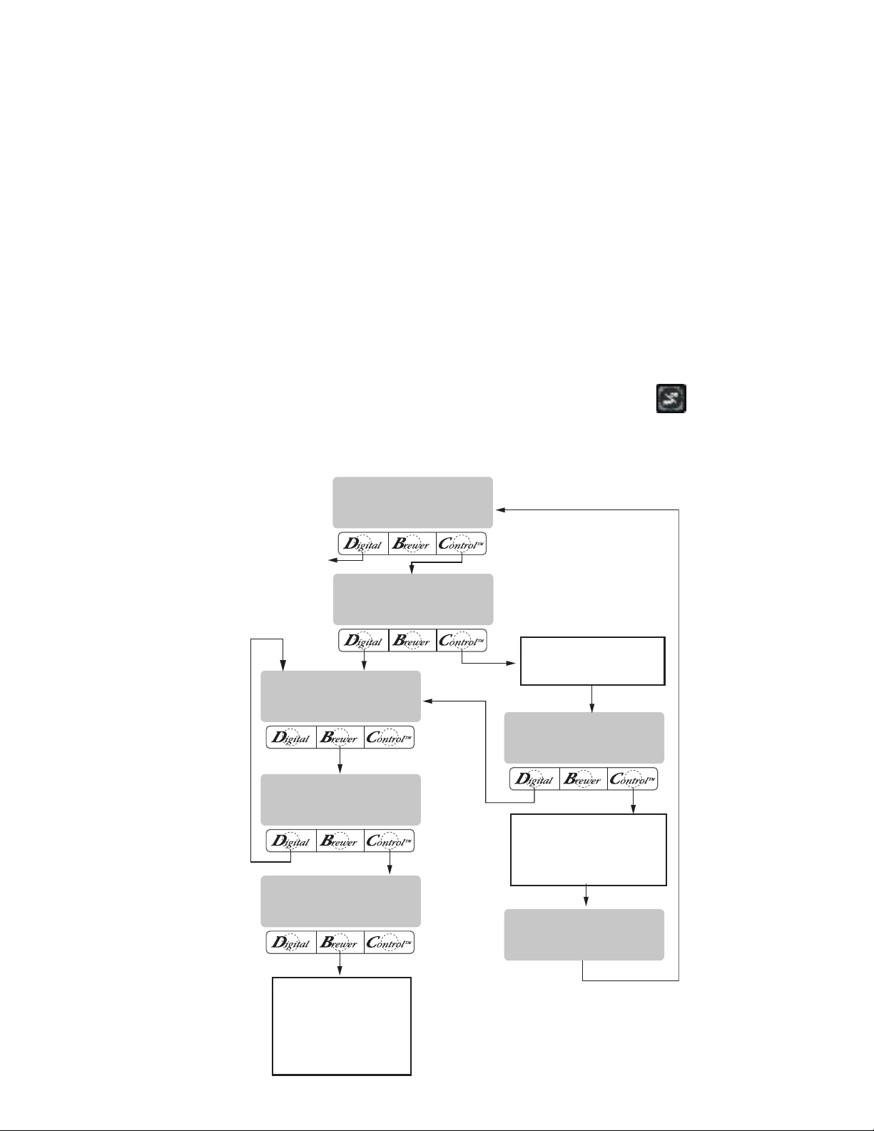
REVIEW RECIPES?
NO YES
3 BATCHES DONE?
NO YES
BREW OZ. XX.X
(-) DONE (+)
% BYPASS XX.X
(-) DONE (+)
NO-NAME
MODIFYSHOWNEXT
(COFFEE NAME)
MODIFYSHOWNEXT
THAT WAS THE
LAST RECIPE
EXIT TO
NEXT FUNCTION
SCREEN
ADVANCES TO ALL OTHER
COFFEE NAMES PROGRAMMED
IN THE BREWER'S MEMORY
WHEN THE LAST COFFEE NAME
IN THE BREWER'S MEMORY IS
DISPLAYED, PRESSING NEXT
WILL EXIT AND THE DISPLAY
WILL THEN READ:
SEE MODIFYING
BYPASS PERCENTAGES
ON THE FOLLOWING PAGE
OR PRESS AND RELEASE
ON/OFF SWITCH TO EXIT THE
BREW OZ: SETUP AND RETURN
TO THE MAIN SCREEN
PROGRAMMING FUNCTIONS - LEVEL 2 (cont.)
BREW OZ (SETTING OR ADJUSTING BREW VOLUMES)
This function allows adjustment of the brew volumes for each batch. The indicator signifies volume
in ounces per batch.
Procedure for modifying recipes - brew ounces:
Range: 10.0 oz to 400 oz for all three batch sizes
1. Press and hold the ® pad until the display reads
SET NEW RECIPES. Release the ® pad. Press the
® until the display reads REVIEW RECIPES.
2. Press YES to proceed. The display should now
read NO NAME, along with MODIFY, SHOW and
NEXT.
3. Press and release NEXT to advance to the desired
coffee name to be modified.
4. Press and release MODIFY. The display should
read BREW OZ and a batch light will be blinking.
Press and release the batch size to be modified.
5. Using (-) and (+), set the amount of brew water,
in ounces, to be dispensed over the grounds for
that particular batch size.
6. When finished, press another batch size and repeat step #5 for that size for each batch size to be
modified. Continue setting all batch sizes.
7. When finished setting all batch sizes, press and
release DONE. The display should read 3 BATCH
SIZES DONE?
8. If the three batch sizes are not correct, press and
release NO to return to the BREW OUNCES setup
screen and repeat steps 5, 6 and 7.
9. If the three batch sizes are correct, press YES. This
will advance to the % BYPASS function. Another
alternative is to press the
pad to exit the BREW
OZ setup and return to the MAIN SCREEN.
P2443
34025 022509
Page 19
Page 20
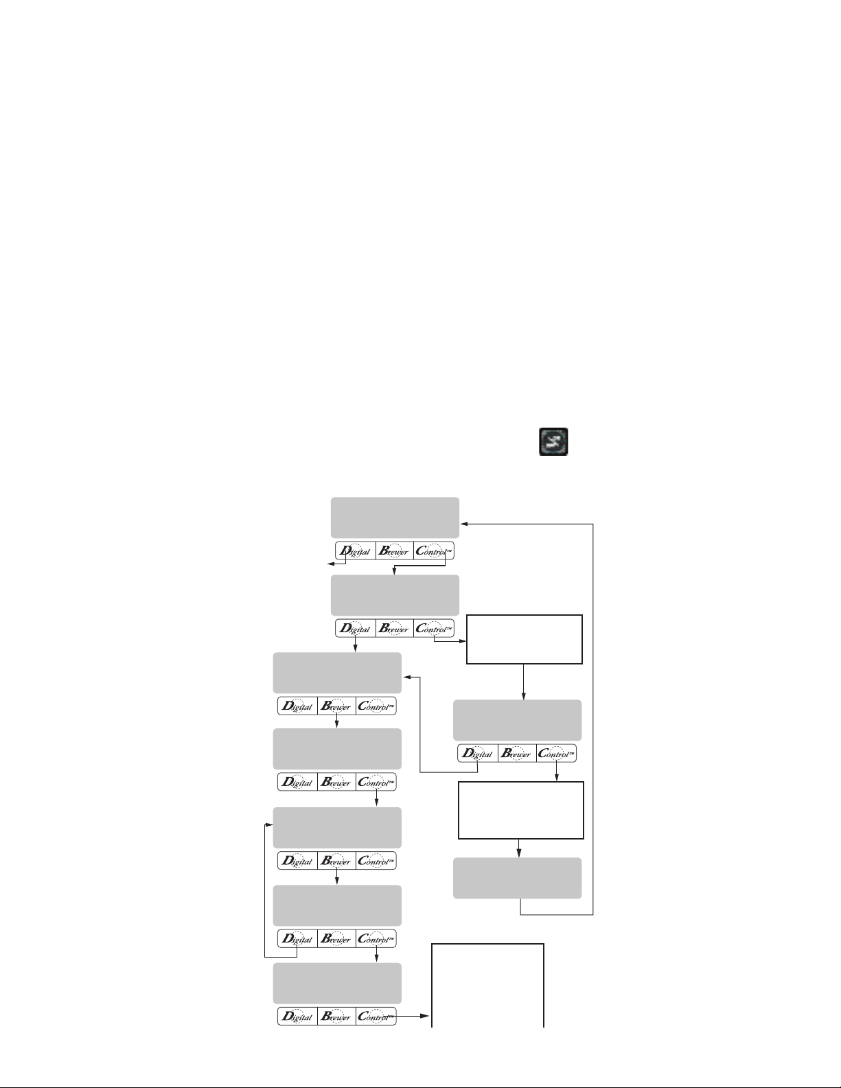
PROGRAMMING FUNCTIONS - LEVEL 2 (cont.)
REVIEW RECIPES?
NO YES
3 BATCHES DONE?
NO YES
3 BATCHES DONE?
NO YES
SET PULSE BREW?
NO YES
BREW OZ. XX.X
(-) DONE (+)
% BYPASS XX.X
(-) DONE (+)
NO-NAME
MODIFYSHOWNEXT
(COFFEE NAME)
MODIFYSHOWNEXT
THAT WAS THE
LAST RECIPE
EXIT TO
NEXT FUNCTION
SCREEN
ADVANCES TO ALL OTHER
COFFEE NAMES PROGRAMMED
IN THE BREWER'S MEMORY
WHEN THE LAST COFFEE NAME
IN THE BREWER'S MEMORY IS
DISPLAYED, PRESSING NEXT
WILL EXIT AND THE DISPLAY
WILL THEN READ:
SEE MODIFYING
PULSE BREW ON
THE FOLLOWING PA GE
OR PRESS AND RELEASE
ON/OFF SWITCH TO EXIT THE
% BYPASS SETUP AND
RETURN TO THE MAIN SCREEN
% BYPASS
This function allows adjustment of the amount of
water that bypasses the grounds. The number signifies the percentage of the brew volume which does
not flow over the coffee grounds.
Modifying recipes - bypass percentages:
Range: 0% to 90% for all three batch sizes
NOTE: If the brewer is already in the % BYPASS screen,
it is not necessary to follow steps 1 through 6 in this
section, but proceed directly to step 7.
1. Press and hold the ® pad until the display reads
SET NEW RECIPES. Release the ® pad. Press the
® until the display reads REVIEW RECIPES.
2. Press YES to proceed. The display should now
read NO NAME, along with MODIFY, SHOW and
NEXT.
3. Press and release NEXT to advance to the desired
coffee name to be modified.
4. Press and release MODIFY. The display should
read BREW OZ.
5. Press and release DONE. The display should read
3 BATCHES DONE?.
6. Press and release YES. The display should now
read % BYPASS, and a batch light will be blinking.
Press and release the batch size to be modified.
7. Using (-) and (+) set the amount of bypass water
(percentage) to be dispensed around the grounds
for that particular batch size.
8. When finished, press another batch size and repeat
step #7 for each batch to be modified.
9. When finished setting all batch sizes, press DONE.
The display should read 3 BATCHES DONE?
10. If they are not correct, press and release NO to
return to the % BYPASS setup screen.
11. If the 3 batch sizes are correct, press YES. This will
advance to SET PULSE BREW. Another alternative
is to press the
pad to exit the % BYPASS setup
and return to the MAIN SCREEN.
P2444
34025 022509
Page 20
Page 21
PROGRAMMING FUNCTIONS - LEVEL 2 (cont.)
INITIAL SPRAY
INITIAL SPRAY
ALTERNATES UNTIL
BREW CYCLE IS
COMPLETED
PRE-INFUSION
REMAINING ON
ON-
TIME
OFF-
TIME
OFF-TIME
OFF-
TIME
OFFTIME
ON-
TIME
ON-
TIME
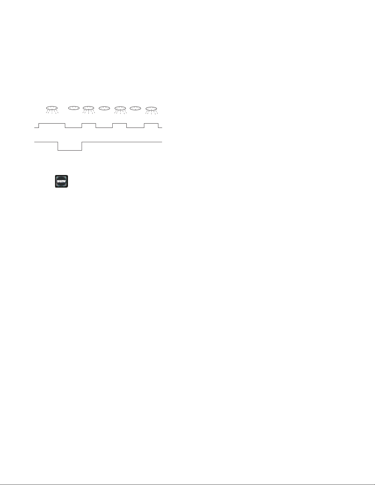
SET PULSE BREW:
This function allows the operator to program
the brewer to "pulse” the sprayhead flow on and off
during a brew cycle (start and stop the flow of water
out of the sprayhead). This feature allows the ability
to “fine-tune” the brewer for specific flavor profiles.
Pulse brewing can be set up for any and all batches.
P2293
a) 1st ON TIME - This time is the duration from when
the pad is pressed to when the desired water level in the funnel is reached. (Soaking the
grounds)
b) OFF-TIME - This time is the duration from when
the water in the funnel reaches the desired ON
TIME level to when it drains out of the funnel to a
desired lower level.
c) LAST ON-TIME- This time is the duration from when
the water in the funnel drains down to the lower
level to when it fills the funnel to a desired higher
level. (Soaking the grounds).
These three times can be set two different ways.
The first is by observing the flow of water for on and
off times. This is accomplished by utilizing the SET BY
EXAMPLE screen and following the subsequent steps
under that function.
The other allows the actual times to be entered
for each of the settings. This is done by utilizing the
ENTER TIMES screen and following the subsequent
steps under that function.
Either of these methods can be used to set the
pulse brew for each batch.
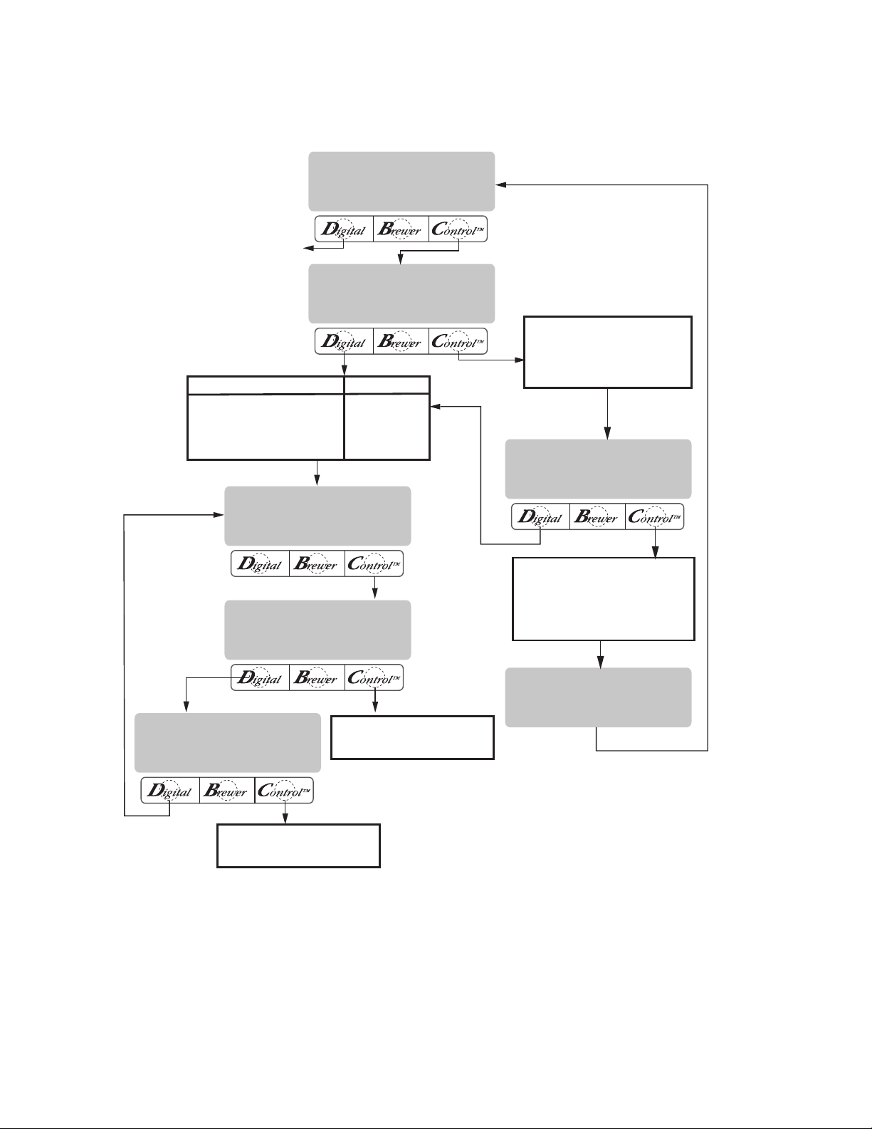
Modifying pulse brew:
Range: 1st on time - off to 4 minutes
Off time - off to 4 minutes
Last on time - off to 4 minutes
NOTE: If the brewer is already in the SET PULSE BREW
screen, it is not necessary to follow steps 1 through 8
in this section, but proceed directly to step 9.
1. Press and hold the ® pad until the display reads
SET NEW RECIPES. Release the ® pad. Press the
® until the display reads REVIEW RECIPES.
2. Press YES to proceed. The display should now
read NO NAME, along with MODIFY, SHOW and
NEXT.
3. Press and release NEXT to advance to the desired
coffee name to be modified.
4. Press and release MODIFY. The display should
read BREW OZ.
5. Press and release DONE. The display should read
3 BATCHES DONE?.
6. Press and release YES. The display should now
read % BYPASS.
7. Press and release DONE. The display should read
3 BATCHES DONE?.
8. Press and release YES. The display should now
read SET PULSE BREW.
9. Press and release YES. The display should now
read SET BY EXAMPLE.
10. If setting Pulse brew BY EXAMPLE (brewing into
a funnel) press YES and proceed with the setup
instructions for SETTING PULSE BREW - BY EX-
AMPLE, on page 23.
11. If setting Pulse brew by ENTER TIMES (entering
known times) press NO. The display should read
ENTER TIMES. Press and release YES and proceed
with the setup instructions for SETTING PULSE
BREW - ENTER TIMES, page 24.
34025 022509
Page 21
Page 22
EXIT TO
NEXT FUNCTION
SCREEN
PRESS
DONE
YES
DONE
YES
SCREEN DISPLAYED
BREW OZ: XX.XX
3 BATCHES DONE?
% BYPASS XX.X
3 BATCHES DONE?
ADVANCES TO ALL OTHER
COFFEE NAMES PROGRAMMED
IN THE BREWER'S MEMORY
WHEN THE LAST COFFEE NAME
IN THE BREWER'S MEMORY IS
DISPLAYED, PRESSING NEXT
WILL EXIT AND THE DISPLAY
WILL THEN READ:
SEE PULSE BREW SETUP-
(EASY PULSE SETUP)
SEE PULSE BREW SETUP-
(ENTER TIMES)
REVIEW RECIPES?
NO YES
SET PULSE BREW?
NO YES
SET BY EXAMPLE?
NO YES
ENTER TIMES?
NO YES
<RECIPE NAME>
MODIFYSHOWNEXT
THAT WAS THE
LAST RECIPE
NO-NAME
MODIFYSHOWNEXT
PROGRAMMING FUNCTIONS - LEVEL 2 (cont.)
SET PULSE BREW (cont.)
P2445
34025 022509
Page 22
Page 23
PROGRAMMING FUNCTIONS - LEVEL 2 (cont.)
SET BY EXAMPLE
RETURN TO
SET BY EXAMPLE
SEE MODIFYING
PREINFUSION
5 SEC. DELAY
CONTAINER RDY?
QUIT YES
PRESS BREW TO
SET 1ST ON TIME
PRESS BREW TO
END 1ST ON TIME
PRESS BREW TO
END OFF TIME
PRESS BREW TO
END LAST ON TIME
1ST OFF LAST
X:XX X:XX X:XX
SET PREINFUSION?
NO YES
3 BATCHES DONE?
NO YES
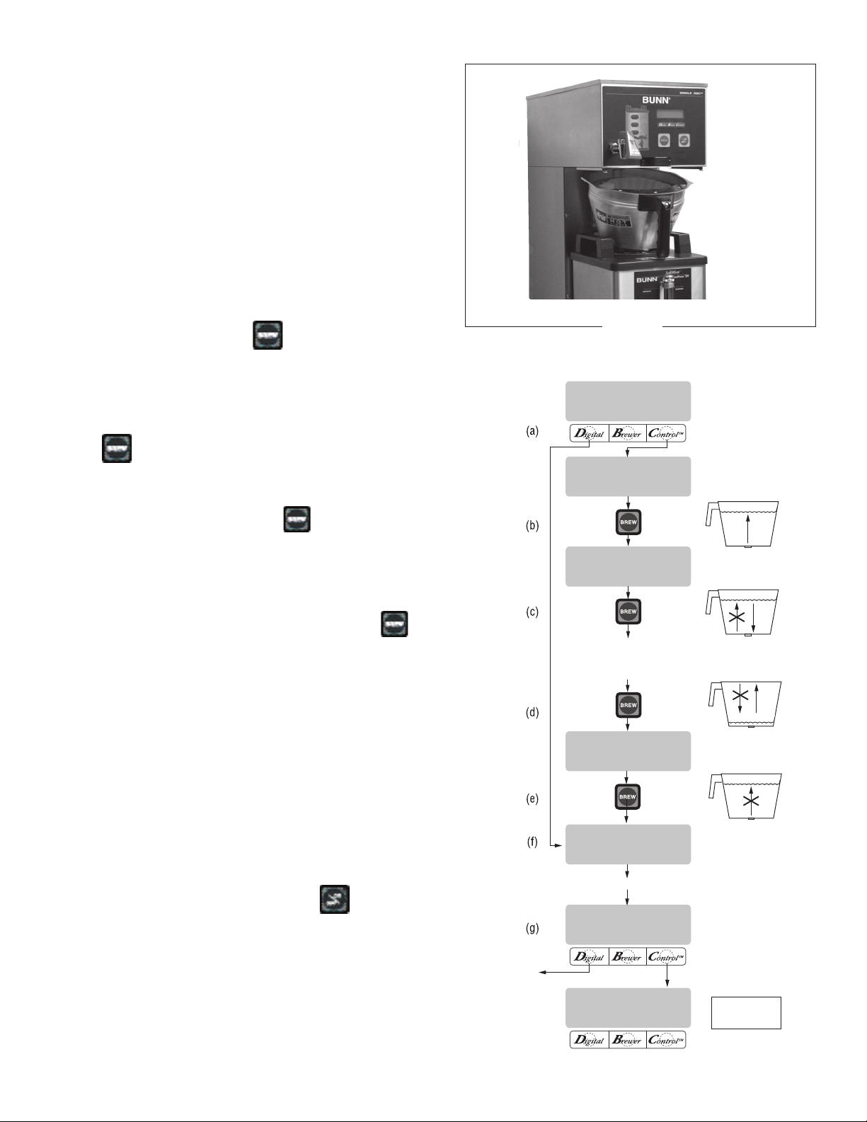
Setting Pulse Brew - BY EXAMPLE:
1. This display should read CONTAINER READY?
Place a container under the sprayhead. Place a
brew funnel containing a filter and grounds on top
of the container so that the spray and coffee bed
can be viewed. (See Fig. 1)
2. Choose the batch size to be set by pressing the pad
next to the indicator light on the left brew side. The
batch size indicator selected will be flashing.
3. If everything is in place, press YES in the CON-
TAINER READY? screen. The display should read
PRESS BREW TO START 1ST ON TIME.(a)
4. Press and release the
will start to flow into the funnel and the water level
will rise.(b)
5. Watch the flow of water. When it reaches the
desired level in the funnel, press and release the
pad again to end the 1ST ON TIME.(c)
6. The spray will stop and the brew funnel will start
to empty. When the water level in the funnel drains
to the desired level, press
OFF-TIME. This also begins the spray of water for
the final setting.(d)
7. The brew water will begin again and the water level
in the funnel will rise. Watch the flow of water.
When it reaches the desired level, press to
end the LAST ON TIME.(e)
8. The display should now show the 1st, off and last
times for the batch size just programmed. After a
5 second delay, the display will read 3 BATCHES
DONE? (f and g)
9. If other batches need to be modified, press NO.
The display will go back to SET BY EXAMPLE.
Press YES, then press a different batch size pad
and repeat steps 1 through 8. Repeat until all the
desired batch sizes are set for the left side. (g)
10. When finished press YES in 3 BATCHES DONE?.
The display will then read SET PREINFUSION.
Another alternative is to press the
on the front panel of the brewer to exit SET PULSE
BREW and return to the MAIN SCREEN.
pad. The brew water
again to end the
pad located
P2452
FIG. 1
NOTE: Pressing ® before reaching the final setting
screen exits the setup and retains the old values.
Page 23
P2410
34025 022509
Page 24
PROGRAMMING FUNCTIONS - LEVEL 2 (cont.)
ENTER TIMES
RETURN TO
SET BY EXAMPLE
5 SEC. DELAY
SEE MODIFYING
PREINFUSION
OFF TIME X:XX
(-) DONE (+)
1ST ON TIME X:XX
(-) DONE (+)
LAST ON TIME X:XX
(-) DONE (+)
1ST OFF LAST
X:XX X:XX X:XX
3 BATCHES DONE?
NO YES
SET PREINFUSION?
NO YES
(a)
(b)
(c)
(d)
(e)
(f)
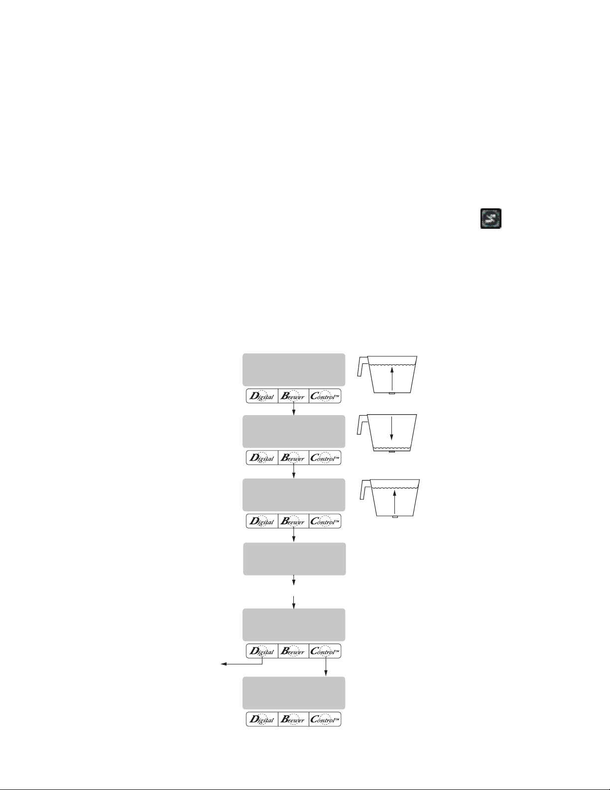
Setting Pulse Brew - ENTER TIMES:
NOTE: No water should flow from the brewer during
this set-up process.
1. This display should read 1ST ON TIME X:XX.
Choose the batch size to be set by pressing the pad
next to the indicator light on the front panel. The
batch size indicator selected will be flashing.
2. Adjust the 1ST ON TIME using (-) and (+). When
finished, press DONE. (a)
3. The display will now read OFF TIME X:XX. Adjust
the OFF TIME using (-) and (+). When finished,
press DONE.(b)
4. The display will now read LAST ON TIME X:XX.
Adjust the LAST ON TIME using (-) and (+). When
finished, press DONE.(c)
5. The display will show the three times just entered
for that batch size. After a 5 second delay, the
display will read 3 BATCHES DONE?(d and e)
6. If other batch sizes need to be modified, press NO.
The display will then read SET BY EXAMPLE.
7. In that screen, press NO. The display should now
read ENTER TIMES.
8. Press YES in this screen, then press a different
batch size pad and repeat steps 2 through 4. Repeat until all the desired batch sizes are set for the
left side.
9. When finished press YES in 3 BATCHES DONE?.
The display will then read SET PREINFUSION.
Another alternative is to press the
pad located
on the front panel of the brewer to exit SET PULSE
BREW and return to the MAIN SCREEN.
NOTE: Pressing ® before reaching the final setting
screen exits the setup and retains the old values.
P2411
34025 022509
Page 24
Page 25
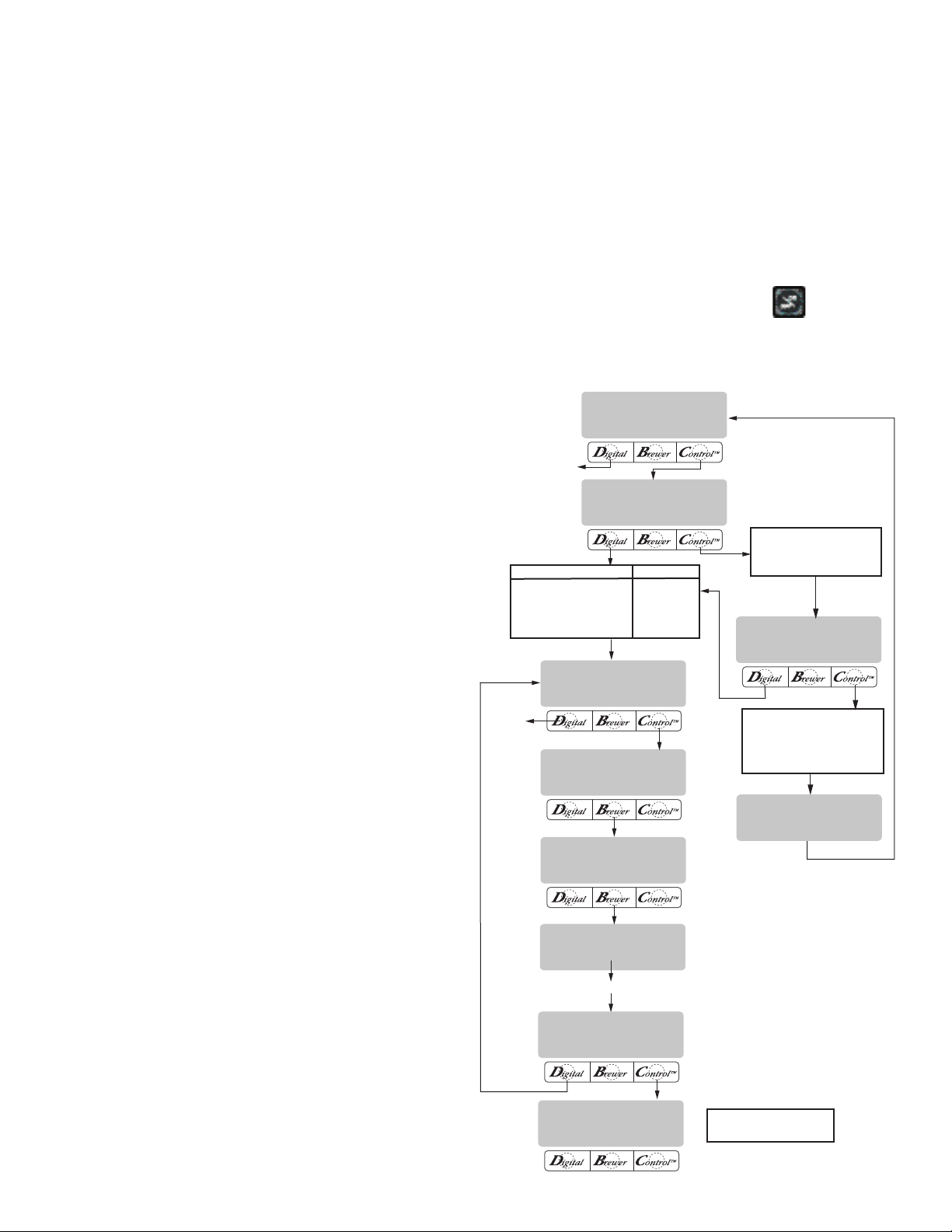
PROGRAMMING FUNCTIONS - LEVEL 2 (cont.)
REVIEW RECIPES?
NO YES
SET PREINFUSION?
NO YES
3 BATCHES DONE?
NO YES
ON OFF
X:XX X:XX
OFF TIME X:XX
(-) DONE (+)
DRIP TIME X:XX
(-) DONE (+)
ON TIME X:XX
(-) DONE (+)
(COFFEE NAME)
MODIFYSHOWNEXT
THAT WAS THE
LAST RECIPE
NO-NAME
MODIFYSHOWNEXT
EXIT TO
NEXT FUNCTION
SCREEN
ADVANCES
TO NEXT
SCREEN
5 SEC. DELAY
PRESS
DONE
YES
DONE
YES
NO
SCREEN DISPLAYED
BREW OZ: XX.XX
3 BATCHES DONE?
% BYPASS XX.X
3 BATCHES DONE?
SET PULSE BREW?
ADVANCES TO ALL OTHER
COFFEE NAMES PROGRAMMED
IN THE BREWER'S MEMORY
WHEN THE LAST COFFEE NAME
IN THE BREWER'S MEMORY IS
DISPLAYED, PRESSING NEXT
WILL EXIT AND THE DISPLAY
WILL THEN READ:
SEE MODIFYING
DRIP TIMES
SET PREINFUSION
This function allows the operator to set an initial
soaking of the grounds and a delay time, before the
complete brew cycle starts.
Procedure for Modifying preinfusion times:
Range: On time - off to 4 minutes
Off time - off to 4 minutes for all three batch
sizes
NOTE: If the brewer is already in the SET PREINFUSION
screen, it is not necessary to follow steps 1 through 9
in this section, but proceed directly to step 10.
1. Press and hold the ® pad until the display reads
SET NEW RECIPES. Release the ® pad. Press the
® until the display reads REVIEW RECIPES.
2. Press YES to proceed. The display should now
read NO NAME, along with MODIFY, SHOW and
NEXT.
3. Press and release NEXT to advance to the desired
coffee name to be modified.
4. Press and release MODIFY. The display should
read BREW OZ.
5. Press and release DONE. The display should read
3 BATCHES DONE?.
6. Press and release YES. The display should now
read % BYPASS.
7. Press and release DONE. The display should read
3 BATCHES DONE?.
8. Press and release YES. The display should now
read SET PULSE BREW.
9. Press and release NO. The display should now
read SET PREINFUSION.
10. Press YES to proceed. The display should now
read ON TIME and a batch light will be blinking.
11. Using (-) and (+), set the amount of time the brew
water will initially presoak the grounds for that
particular batch size.
12. When finished, press another batch size and repeat
until all three batch sizes are set.
13. When finished, press DONE. The display should
now read OFF TIME and a batch light will be blink-
ing.
14. Using (-) and (+), set the amount of time the brew
cycle will delay (after the presoak cycle shuts off)
before resuming brewing.
15. When finished, press another batch size and repeat
until all three batch sizes are set.
Page 25
16. When finished, press DONE. The display will show
the ON and OFF TIMES that were entered for a
particular batch size.
17. After a 5 second delay, the display should read
3 BATCHES DONE?. If the three batches are not
complete, press NO in order to return to SET
PREINFUSION, and repeat steps 10 through 14.
18. If the three batches are done, press YES. This will
advance to the next function, SET DRIP TIME. An-
other alternative is to press the
pad located
on the front panel of the brewer to exit SET PULSE
BREW and return to the MAIN SCREEN.
P2446
34025 022509
Page 26
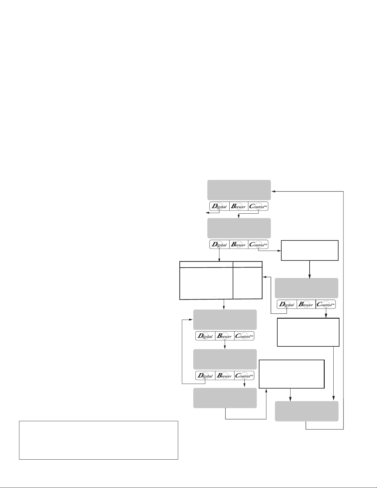
PROGRAMMING FUNCTIONS - LEVEL 2 (cont.)
REVIEW RECIPES?
NO YES
3 BATCHES DONE?
NO YES
DRIP TIME X:XX
(-) DONE (+)
NO-NAME
MODIFYSHOWNEXT
EXIT TO
NEXT FUNCTION
SCREEN
ADVANCES TO ALL OTHER
COFFEE NAMES PROGRAMMED
IN THE BREWER'S MEMORY
WHEN THE LAST COFFEE NAME
IN THE BREWER'S MEMORY IS
DISPLAYED, PRESSING NEXT
WILL EXIT AND THE DISPLAY
WILL THEN READ:
EXITS TO THE NEXT COFFEE NAME
IN THE BREWER'S MEMORY. IF NO
OTHER COFFEE NAMES ARE
ENTERED IN THE BREWER'S
MEMORY, THE DISPLAY WILL READ:
(COFFEE NAME)
MODIFYSHOWNEXT
(COFFEE NAME)
SETUP COMPLETE
THAT WAS THE
LAST RECIPE
PRESS
DONE
YES
DONE
YES
NO
NO
SCREEN DISPLAYED
BREW OZ: XX.XX
3 BATCHES DONE?
% BYPASS XX.X
3 BATCHES DONE?
SET PULSE BREW?
SET PREINFUSION?
DRIP TIME (now displayed on "non" funnel lock
units as well)
This function allows the setting or modification
of the funnel locks to stay engaged after the end of
a brew cycle. This ensures that the funnel cannot be
removed until after the liquid has emptied out of the
funnel.
Procedure to modify drip times:
Range: OFF to 10 minutes for all three batch
sizes.
NOTE: If the brewer is already in the DRIP TIMES
screen, it is not necessary to follow steps 1 through
10 in this section, but proceed directly to step 11.
1. Press and hold the ® pad until the display reads
SET NEW RECIPES. Release the ® pad. Press the
® until the display reads REVIEW RECIPES.
2. Press YES to proceed. The display should now
read NO NAME, along with MODIFY, SHOW and
NEXT.
3. Press and release NEXT to advance to the desired
coffee name to be modified.
4. Press and release MODIFY. The display should
read BREW OZ.
5. Press and release DONE. The display should read
3 BATCHES DONE?.
6. Press and release YES. The display should now
read % BYPASS.
7. Press and release DONE. The display should read
3 BATCHES DONE?.
8. Press and release YES. The display should now
read SET PULSE BREW.
9. Press and release NO. The display should now
read SET PREINFUSION.
10. Press and release NO. The display should now read
DRIP TIME, along with either the word OFF, or a
time will be showing. A batch light should also be
blinking.
11. Using the (-) and (+), set the amount of time from
when the brew solenoid shuts off to when drip-out
occurs for that batch size.
NOTE: Set to OFF to prevent funnel locks from engag-
ing (to disable this function), for a particular batch
size. To set to OFF, press and release (-) until OFF is
displayed.
Page 26
12. When finished, press another batch size and repeat
step 11 until all three batches are set.
13. When finished, press DONE. The display should
read 3 BATCHES DONE?
14. If the three batch sizes are set correctly, press YES.
The screen should show the name of the coffee
flavor being programmed (modified) along with
SETUP COMPLETE.
15. After a 5 second delay, the display will advance to
the next coffee name in the brewer's memory. If
no other coffee names are present, the display will
read THAT WAS THE LAST RECIPE, and return to
the REVIEW RECIPES screen.
P2447
34025 022509
Page 27
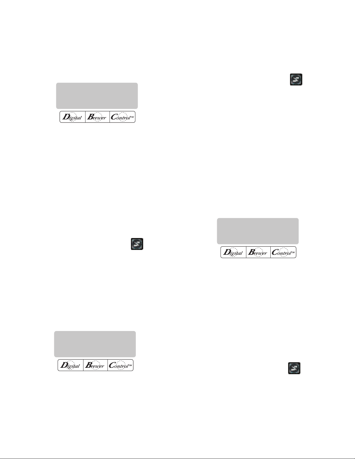
ENABLE ADS?
NO DONE YES
PROGRAMMING FUNCTIONS - LEVEL 2 (cont.)
SET TEMP: XXX°
(-) DONE (+)
SET READY: XXX°
(-) DONE (+)
ENABLE ADS?
This function allows the operator to choose whether
or not to display the advertising message that was entered into the brewer with an AD CARD. This message
will be displayed when the brewer is not in use.
P2301
Procedure to Enable/Disable Ads:
1. Press and hold the ® pad until the display reads
SET NEW RECIPES. Release the ®. Press and
release the ® until the display reads ENABLE
ADS. The YES or NO will be flashing to indicate
the current selection.
2. Press and release the NO pad to disable this func-
tion (no ads will be displayed on the screen), or;
3. Press and release the YES pad to enable this func-
tion (ads will be displayed on screen).
4. When finished, press and release DONE to save
the new setting, exit the ENABLE ADS function and
advance to the next function screen, SET TEMP.
2. To adjust the brew temperature, press (-) to decrease or (+) to increase the brew temperature.
3. When finished, press and release DONE to save
the new setting, exit the SET TEMP function and
advance to the next function screen, SET READY.
Another alternative is to press the
pad located
on the front switch panel to exit the SET TEMP
function and return to the MAIN SCREEN.
SET READY - Range: 185˚F (85˚C) to 203˚F(95˚C)
This function allows the operator to set the minimum temperature allowable to start a brew cycle. The
range can be from 185˚F (85˚C) to within 2˚F of the SET
TEMP. The water must be at the SET READY tempera-
ture or higher for the display to indicate READY TO
BREW. If brew lockout is enabled, the brewing process
will not start below this READY temperature.
NOTE: The upper limit is the water temperature control
setting minus 2˚F.
Another alternative is to press the
pad located
on the front switch panel to exit the ENABLE ADS
function and return to the MAIN SCREEN.
SET TEMP - Range: 185˚F (85˚C) to 205˚F(96˚C)
This function allows the operator to set the brew
water temperature in the tank. It also sets the hot
water faucet dispense temperature.
P2302
Procedure to set brew temperature:
1. Press and hold the ® pad until the display reads
SET NEW RECIPES. Release button. Press and
release the ® until the display reads SET TEMP.
P2303
Procedure to set ready temperature:
1. Press and hold the ® pad until the display reads
SET NEW RECIPES. Release the ® pad. Press
and release the ® pad until the display reads SET
READY.
2. To adjust the ready temperature, press the (-)
button to decrease, or (+) to increase the ready
temperature.
3. When finished, press and release DONE to save
the new setting, exit the SET READY function and
advance to the next function screen, REFILL. An-
other alternative is to press the
pad located
on the front switch panel to exit the SET READY
function and return to the MAIN SCREEN.
Page 27
34025 022509
Page 28
BYPASS OZ/M: XX.X
(-) DONE (+)
XXX REFILL XXX
(-) DONE (+)
SPRAY OZ/M: XX.X
(-) DONE (+)
PROGRAMMING FUNCTIONS - LEVEL 2 (cont.)
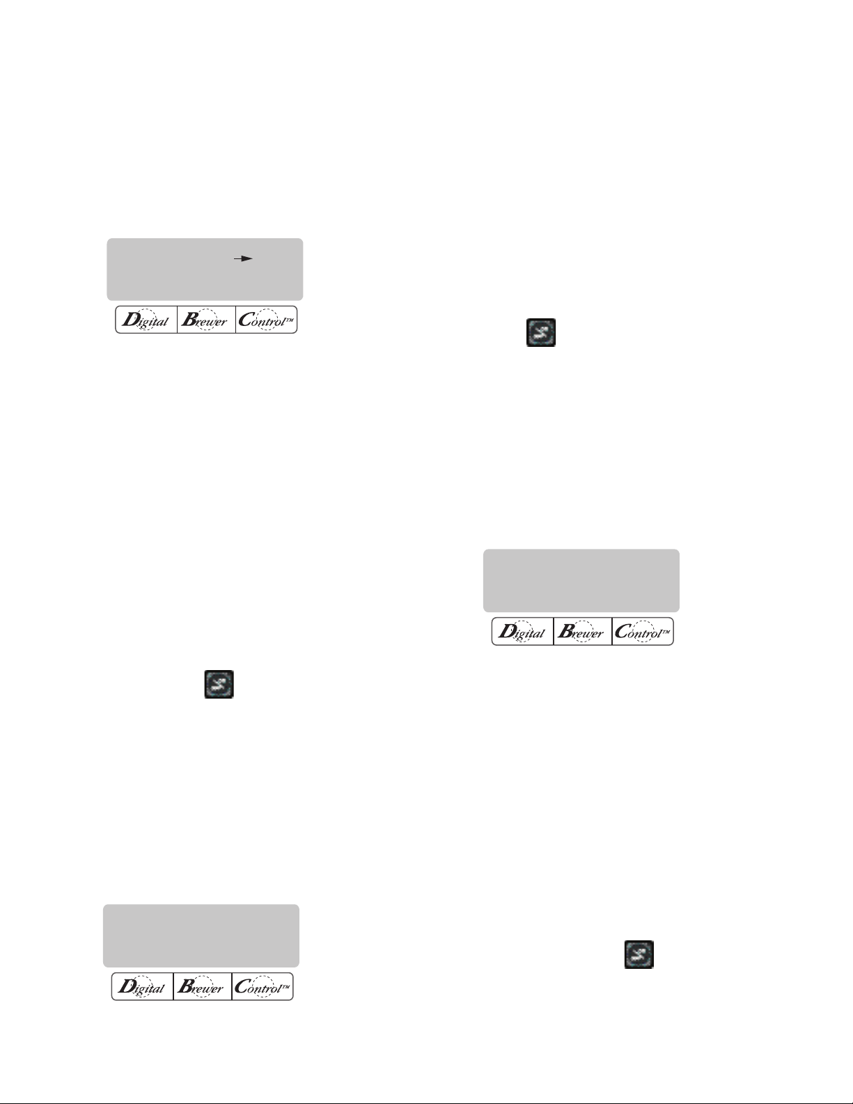
REFILL - Range: 20 to 230
This function allows the operator to adjust the
sensitivity of the refill circuit. This is mainly a troubleshooting feature. Water in different geographical locations can have different conductivities. By adjusting
the sensitivity of the refill circuit, this will allow the
brewer to operate under various water conditions.
P2304
Procedure to set the sensitivity threshold of the
refill circuit:
NOTE: Make sure the water in the tank is touching
the refill probe.
1. Press and hold the ® until the display reads SET
NEW RECIPES. Release the ®. Press and release
the ® pad until the display reads REFILL and shows
a number on both sides of the word.
2. To adjust the threshold setting, press (-) to decrease, or (+) to increase the setting.
NOTE: Always make sure that the number on the right
is larger than the number on the left when water is in
contact with the refill probe in the tank.
3. When finished, press and release DONE. This
saves the new setting and advances to the next
function screen, SPRAY OZ/M. Another alterna-
tive is to press the
pad located on the front
switch panel to exit REFILL and return to the MAIN
SCREEN.
SPRAY OZ/M
This function allows the operator to view or to enter
the actual flow rate coming out of the sprayhead. This
is NOT used to change the actual flow rate, but to tell
the internal controller how fast the water is flowing.
The unit of measure is ounces per minute. (Oz/M)
SET NEW RECIPES. Release the ®. Press and
release the ® pad until the display reads SPRAY
OZ/M. The number represents what the brewer
thinks is the flow rate of the sprayhead valve in
ounces per minute.
2. If the actual flow rate of the sprayhead valve is
known, but is different than the number on the
display, use the (-) and (+) pads to enter the correct flow rate in ounces per minute.
3. When finished, press and release DONE. This saves
the new setting and advances to the next function
screen, BYPASS OZ/M. Another alternative is to
press the
pad located on the switch panel to
exit SPRAY OZ/M function and return to the MAIN
SCREEN.
BYPASS OZ/M
This function allows the operator to view or to enter
the actual flow rate coming out of the bypass nozzle.
This is NOT used to change the actual flow rate, but to
tell the internal controller how fast the water is flowing.
The unit of measure is ounces per minute.
P2306
Procedure to adjust the flow rate setting:
1. Press and hold the ® pad until the display reads SET
NEW RECIPES. Release the ®. Press and release
the ® pad until the display reads BYPASS OZ/M.
The number represents what the brewer thinks
is the flow rate of the bypass valve in ounces per
minute.
2. If the actual flow rate of the bypass valve is known,
but is different than the number on the display, use
the (-) and (+) pads to enter the correct flow rate
in ounces per minute.
3. When finished, press and release the DONE pad.
This saves the new setting and advances to the
next function screen, CALIBRATE FLOW. Another
Procedure to adjust the flow rate setting:
1. Press and hold the ® pad until the display reads
P2305
Page 28
alternative is to press the
pad located on the
front switch panel to exit the BYPASS OZ/M func-
tion and return to the MAIN SCREEN.
34025 022509
Page 29
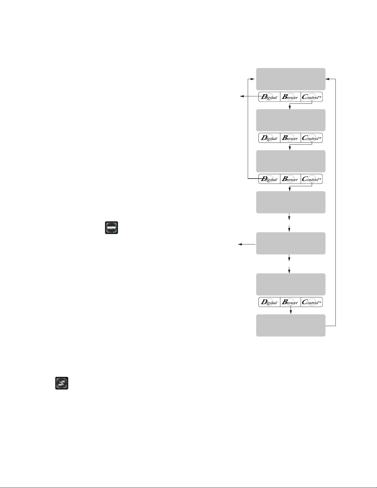
NEW SPRAY FLOW
XX.X OZ/M
ENTER OZ XX.X
(-) DONE (+)
CALIBRATE FLOW?
NO YES
SPRAYHEAD CAL?
NO YES
CONTAINER RDY?
QUIT YES
CALIBRATE SPRAY
PRESSBREWSTART
CALIBRATE SPRAY
60 SEC TO FINISH
COUNTS DOWN
TO ZERO
AFTER 1 MINUTE
BREW PRESSED
EXIT TO THE
NEXT FUNCTION
SCREEN
PROGRAMMING FUNCTIONS - LEVEL 2 (cont.)
CALIBRATE FLOW
This function allows the operator to enter the actual
flow rate of the sprayhead and the bypass by dispensing both separately for one minute. The volumes are
then entered in ounces per minute. (Oz/M)
Procedures to calibrate the sprayhead flow rate:
1. Place a container, accurately graduated in ounces,
and with a minimum capacity of 60 ounces, beneath
the funnel on the brewer.
2. Press and hold the ® pad until the display reads
SET NEW RECIPES. Release the ® pad. Press and
release the ® pad until the display reads CALIBRATE
FLOW.
3. Press and release YES to advance to the SPRAY-
HEAD CAL? function screen. (Pressing NO in the
CALIBRATE FLOW screen will advance to the next
function screen, BREW COUNTERS).
4. Press and release the YES pad. The display should
read CONTAINER READY? If the container is under
the funnel, press YES. The display should read
CALIBRATE SPRAY .. PRESS BREW TO START.
5. Press and release the
pad. The display should
read CALIBRATE SPRAY .. 60 SEC TO FINISH. The
60 second timer on the display will count down to
zero. When the counter reaches zero, the display
will change to ENTER OZ., along with a number
measured in ounces per minute.
6. Measure the amount of water in the container and
using the (-) or (+) pads, adjust the amount on
the display to match the amount in the container.
Then press DONE.
7. The display should now read NEW SPRAY FLOW,
along with the correct flow rate of the sprayhead
in ounces per minute. After about 5 seconds,
the display will return to the CALIBRATE FLOW
screen.
8. To exit the CALIBRATE FLOW program, press NO
to advance to the next function screen, or press
P2307
the
exit the CALIBRATE FLOW function and return to
pad located on the front switch panel to
the MAIN SCREEN.
Page 29
34025 022509
Page 30
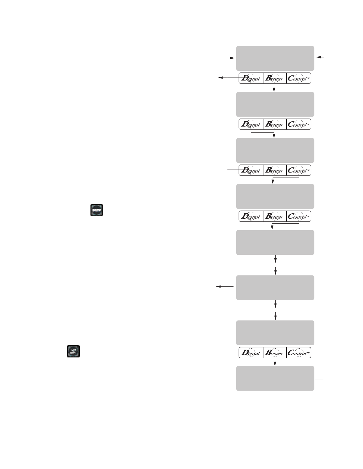
ENTER OZ XX.X
(-) DONE (+)
NEW BYPAS FLOW
XX.X OZ/M
EXIT TO THE
NEXT FUNCTION
SCREEN
COUNTS DOWN
TO ZERO
BREW PRESSED
AFTER 1 MINUTE
CALIBRATE FLOW?
NO YES
CONTAINER RDY?
NO YES
CALIBRATE BYPASS
PRESS BREW START
CALIBRATE BYPASS
60 SEC TO FINISH
BYPASS CAL?
NO YES
SPRAYHEAD CAL?
NO YES
PROGRAMMING FUNCTIONS - LEVEL 2 (cont.)
CALIBRATE FLOW (cont.)
Procedures to calibrate the bypass flow rate:
1. Place a container, accurately graduated in ounces,
2. Press and hold the ® pad until the display reads
3. Press and release YES to advance to the SPRAY-
4. Press and release NO to advance to the BYPASS
5. Press and release the YES pad. The display should
and with a minimum capacity of 60 ounces, below
the funnel on the brewer.
SET NEW RECIPES. Release the ® pad. Press and
release the ® pad until the display reads CALIBRATE
FLOW.
HEAD CAL? function screen. (Pressing NO in the
CALIBRATE FLOW screen will advance to the next
function screen, BREW COUNTERS).
CALIBRATION screen.
read CONTAINER READY? If the container is
under the funnel, press YES. The display should
read CALIBRATE BYPASS .. PRESS BREW TO
START.
6. Press and release the
read CALIBRATE BYPASS .. 60 SEC TO FINISH. The
60 second timer on the display will count down to
pad. The display should
zero. When the counter reaches zero, the display
will change to ENTER OZ., along with a number
measured in ounces per minute.
7. Measure the amount of water in the container, and
using (-) or (+), adjust the amount on the display
to match the amount in the container. Then press
DONE.
8. The display should now read NEW BYPASS FLOW,
along with the correct flow rate of the bypass in
ounces per minute. After about 5 seconds, the display will return to the CALIBRATE FLOW screen.
9. To exit the CALIBRATE FLOW function, press and
pad located on the front switch
release NO to advance to the next function screen,
or press the
panel to exit the CALIBRATE FLOW function and
return to the MAIN SCREEN.
P2314
Page 30
34025 022509
Page 31

EXIT TO
NEXT FUNCTION
SCREEN
XXXX
NEXT RESET
XXXX
NEXT
BREW COUNTERS?
NO YES
FUNNEL DETECT?
NO DONE YES
PROGRAMMING FUNCTIONS - LEVEL 2 (cont.)
BREW COUNTERS
This function allows the operator to track the number of brew cycles completed. There is one resettable
counter, and one life counter that is not resettable.
P2448
Procedures to view/reset the brew counters:
1. Press and hold the ® pad until the display reads
SET NEW RECIPES. Release the ®. Press and
release the ® pad until the display reads BREW
COUNTERS.
2. Pressing NO in this screen will advance to the next
function. Press YES to view the first brew counter.
This number represents the brew cycles initiated
since that counter was last reset.
3. To reset the resettable counter to zero press and
release RESET when viewing that particular coun-
ter's screen.
4. To advance to the other counter, press and release
NEXT. This will advance to total brews (nonresettable).
5. When finished, press NEXT until the display
reads BREW COUNTERS. Press and release NO
to advance to the next function screen, or press
FUNNEL DETECT (optional)
This function allows the operator to prevent the
start of a brew cycle if a Smart Funnel is not positioned
correctly in the funnel rails.
Procedure to set funnel detect:
P2309
1. Press and hold the ® pad until the display reads
SET NEW RECIPES. Release the ®. Press and
release the ® pad until the display reads FUNNEL
DETECT.
2. NO or YES should be flashing to indicate the cur-
rent setting.
3. Select YES to prevent brewing if a Smart Funnel is
not correctly situated in the rails. If this function
is activated and a brew cycle is attempted with the
funnel not properly situated, the display will read,
FUNNEL NOT IN PLACE, until one is in place.
4. Select NO to allow brewing without a Smart Fun-
nel in place. This is selected when brewing with a
funnel other than a Smart Funnel (a regular brew
funnel).
5. When finished, press and release DONE. This will
retain the changes, exit this function screen and
advance to the next. Another alternative is to press
the
pad located on the front switch panel to
exit the FUNNEL DETECT and return to the MAIN
SCREEN.
the
pad on the front switch panel to exit the
BREW COUNTERS function and return to the MAIN
SCREEN.
Page 31
34025 022509
Page 32
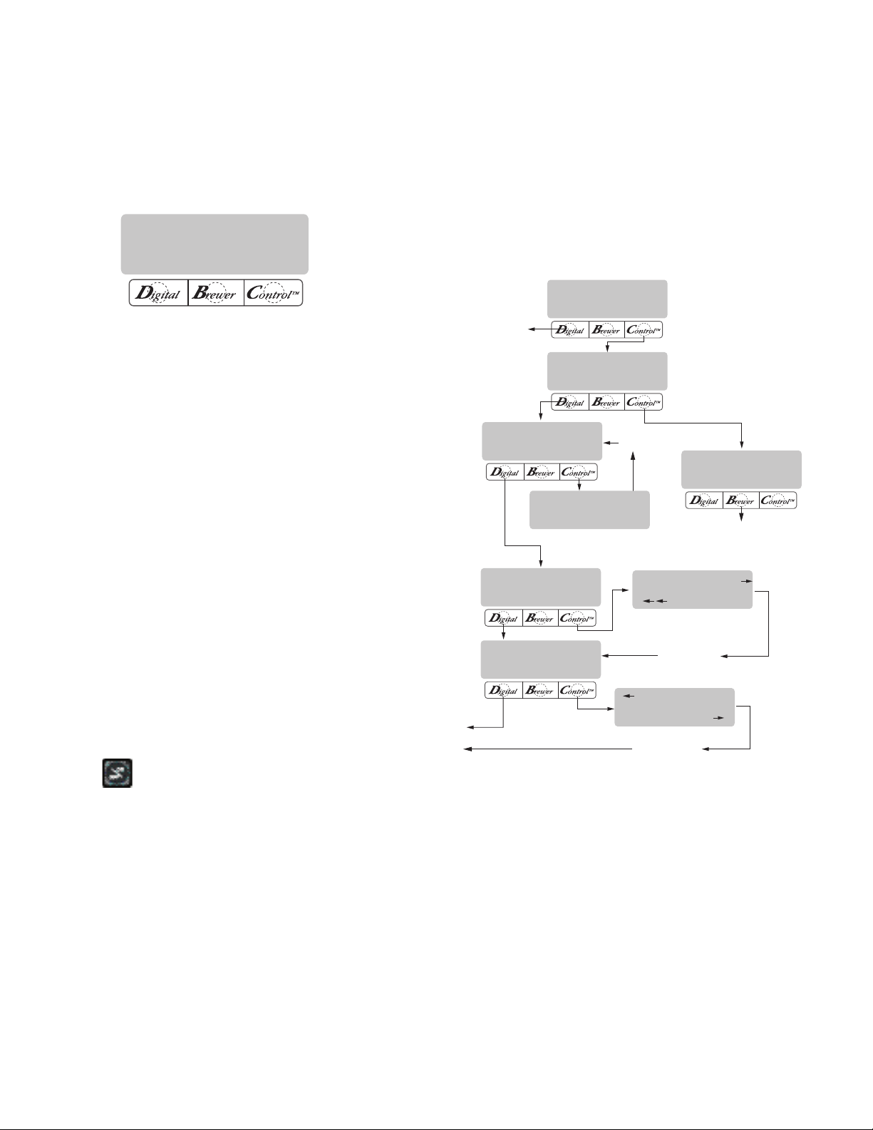
EXIT TO
NEXT FUNCTION
SCREEN
EXIT TO
NEXT FUNCTION
SCREEN
PRESS AND RELEASE
® SYMBOL
PRESS AND RELEASE
® SYMBOL
PRESS AND RELEASE
® SYMBOL
NEXT COMPONENT
TO BE TESTED
TEST OUTPUTS?
NO YES
TEST SWITCHES?
NO YES
BREW V A L V E
ON NEXT OFF
SERVER REMOVED
IN PLACE
125.0 KHZ. 4
4 125.0 KHZ.
NOTHING PRESSED
TEST FREQUENCY?
NO YES
TEST SERVERS?
NO YES
SERVICE TOOLS?
NO YES
SERVER DETECT ?
NO DONE YES
PROGRAMMING FUNCTIONS - LEVEL 2 (cont.)
SERVER DETECT
This function allows the operator to prevent the start
of a brew cycle if a Soft Heat server is not positioned
correctly on the brewer.
P2310
Procedures to set server detect:
1. Press and hold the ® pad until the display reads
SET NEW RECIPES. Release the ®. Press and
release the ® pad until the display reads SERVER
DETECT.
2. The NO or YES flashes to indicate the current
selection.
3. Select YES to prevent brewing if the Soft Heat
server is not correctly positioned on the brewer
beneath the funnel.
SERVICE TOOLS
This function allows the testing of individual components and the ability to check switches for proper
function. This function also tests the Soft Heat server's
status on the brewer (in place or removed), and the
funnel sensor coil's frequency (diagnostic tool for
troubleshooting purposes only).
NOTE: If YES is selected and a brew cycle is attempted
with a server not properly placed, the display will read
SERVER NOT IN PLACE.
4. Select NO to allow brewing without a Soft Heat
server in place. This is selected when brewing into
a container other than a Soft Heat Server.
5. When finished, press and release DONE. This will
save the new setting, exit the function screen and
advance to the next. Another alternative is to press
the
exit the SERVER DETECT function and return to
the MAIN SCREEN.
pad located on the front switch panel to
P2449
Page 32
34025 022509
Page 33
PROGRAMMING FUNCTIONS - LEVEL 2 (cont.)
SERVICE TOOLS (cont.)
Testing individual components (outputs):
This will allow the operator to test the operation
of individual components and outputs of the brewer.
The components that can be individually tested are as
follows:
Brew Valve
Bypass Valve
Funnel Lock (Optional)
Server
Refill Valve
Tank Heaters
Procedure to test components (outputs):
1. Place brew funnels into rails on the brewer.
2. Place a Soft Heat
®
server beneath the brew fun-
nel.
3. Press and hold the ® pad until the display reads
SET NEW RECIPES. Release the ® pad. Continue
pressing and releasing the pad until SERVICE
TOOLS appears.
4. Press YES to run tests on various components
and outputs within the brewer. Pressing NO will
exit this function and advance to the next function
screen.
5. The display should read TEST OUTPUTS.
6. Press and release YES. The display should read
BREW VALVE.
7. To test BREW VALVE, press ON. If the brew valve
is functional, water should run from the brewer.
8. Press OFF to end flow of water.
9. Press NEXT to advance to the next component to
be tested.
NOTE: To bypass testing any component, press NEXT
to advance to the next one, without testing the previous component.
10. To test BREW BYPASS, press ON. If the bypass
valve is functional, water should run from the brew
bypass.
11. Press OFF to end flow of water.
12. Press NEXT to advance to the next component to
be tested.
13. To test FUNNEL LOCK, press ON. If the funnel lock
is functional, the lock will come down to hold the
funnel in place.
14. Press OFF to retract the funnel lock.
15. Press NEXT to advance to the next component to
be tested.
16. To test SERVER, press ON. If the server and the
sensor are functional, the light on the lower right
corner of the server will illuminate.
17. Press OFF to end testing of server.
18. Press NEXT to advance to the next component to
be tested.
19. To test REFILL VALVE, press ON. If the refill valve
is functional, the sound of the valve operating will
be heard.
20. Press OFF to end testing of refill valve.
21. Press NEXT to advance to the next component to
be tested.
22. To test TANK HEATER, connect a voltmeter to the
tank heater to check for voltage.
23. Press ON. The correct voltage should be present
at the heater terminals.
24. Press OFF to end testing of the tank heaters.
NOTE: The tank heater will automatically turn off if
left on too long.
25. After testing the tank heater, press NEXT to advance
to the next test.
26. The SPARE TRIAC is reserved for future use.
27. Press NEXT to return to TEST OUTPUTS.
28. To exit SERVICE TOOLS, press the
pad located
on the front switch panel. This will return to the
MAIN SCREEN.
Procedure to test switches:
This function allows the operator to test the opera-
tion of the individual switches on the front panel.
1. Place brew funnel into rails on the brewer.
2. Place a Soft Heat® server beneath the brew funnel.
3. Press and hold the ® pad until the display reads
SET NEW RECIPES. Release the ® pad. Continue
pressing and releasing the ® pad until SERVICE
TOOLS appears.
4. Press YES to run tests on various components
and outputs within the brewer. (Pressing NO will
exit this function and advance to the next function
screen.)
Page 33
34025 012004
Page 34

PROGRAMMING FUNCTIONS - LEVEL 2 (cont.)
SERVICE TOOLS (cont.)
5. The display should read TEST OUTPUTS.
6. In TEST OUTPUTS screen, press NO. This advances
to TEST SWITCHES.
7. Pressing NO in this screen will advance to the
next function. Press YES in the TEST SWITCHES
screen to test the switches. The display will read
NOTHING PRESSED.
8. From this screen, press any of the switches on the
front of the brewer. While the switch is pressed,
the display shows the name of that switch. If the
name does not appear, or if it remains after the
switch has been released, the switch is defective.
Each switch can be tested in this manner.
9. After all switches have been tested, press the ®
pad located on the front switch panel. This will
exit TEST SWITCHES and return to the MAIN
SCREEN.
Procedures to test server:
This function allows the operator to test the op-
eration of the Soft Heat server. It will also show if the
server is correctly placed on the brewer stand.
1. Place brew funnel into rails of the brewer.
2. Place a Soft Heat server beneath the brew funnel.
3. Press and hold the ® pad until the display reads
SET NEW RECIPES. Release the ® pad. Continue
pressing and releasing the ® pad until SERVICE
TOOLS appears.
4. Pressing NO will exit this function and advance to
the next function screen. Press YES to run tests
on various components and outputs within the
brewer.
5. The display should read TEST OUTPUTS
6. In TEST OUTPUTS screen, press NO. This advances to TEST SWITCHES. Press and release
NO once more. The display should now read TEST
SERVER.
7. Press YES in the TEST SERVER screen to show
if a server is in place. The display should read IN
PLACE.
8. Lift and pull the Soft Heat server forward about 2
inches so that the two contacts on the server do
not touch the two contacts on the brewer.
9. The display should then read SERVER RE-
MOVED.
10. After the servers has been tested, press and release
the
pad located on the front switch panel. This
will exit TEST SERVER and return to the MAIN
SCREEN.
Procedures to test coil frequency:
1. Place brew funnel into rails of the brewer.
2. Place a Soft Heat server beneath the brew funnel.
3. Press and hold the ® pad until the display reads
SET NEW RECIPES. Release the ® pad. Continue
pressing and releasing the ® pad until SERVICE
TOOLS appears.
4. Pressing NO will exit this function and advance to
the next function screen. Press YES to run tests
on various components and outputs within the
brewer.
5. The display should read TEST OUTPUTS.
6. In TEST OUTPUTS screen, press NO. Continue to
press and release NO until the display reads TEST
FREQUENCY.
7. Press and release YES. The display will show the
frequency of the sensor coil circuits. This is for
diagnostic service use when troubleshooting this
circuit.
8. After the coils have been tested, press and release
the
pad located on the front switch panel. This
will exit the TEST FREQUENCY function and return
to the MAIN SCREEN.
NOTE: If the operator wishes to test more than one
function in the SERVICE TOOLS section (outputs,
switches, servers, or coil frequency), it is not
necessary to exit the program. Use the flow chart
for SERVICE TOOLS to navigate to a particular
function.
Page 34
34025 022509
Page 35
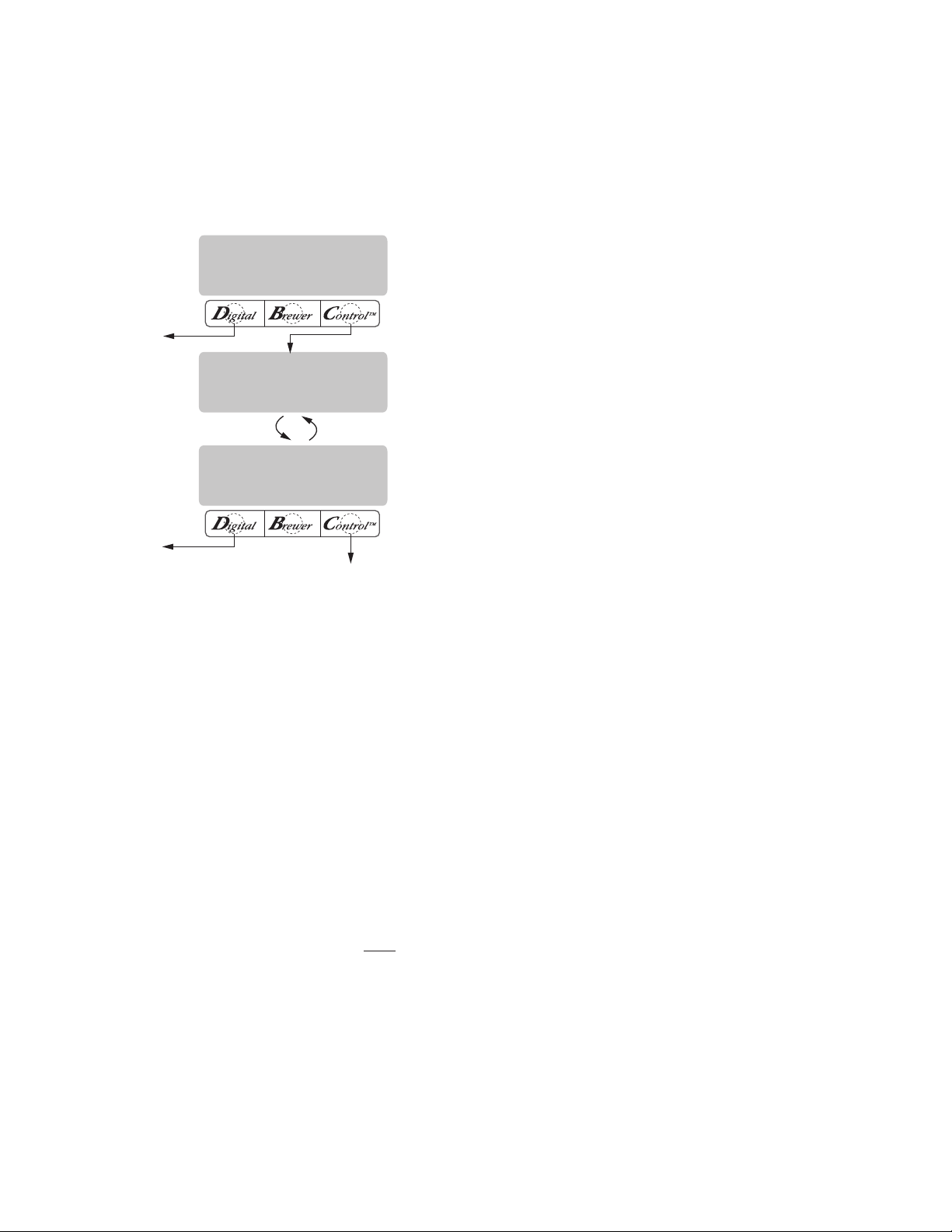
EXIT
EXIT
REPLACE
WILL REPLACE ALL
BREW SETTINGS
ARE YOU SURE?
NO YES
FA CTORY DEFAULTS
NO YES
PROGRAMMING FUNCTIONS - LEVEL 2 (cont.)
FACTORY DEFAULTS
This function allows the operator to erase all of the
previously entered recipes and ad messages. Factoryset default values will replace all previous settings.
P2312
FACTORY DEFAULT VALUES
Brew Lockout YES
BREW VOLUMES:
Small Batch 64 oz.
Medium Batch 128 oz.
Large Batch 192 oz.
BYPASS PERCENTAGE:
Small Batch 0%
Medium Batch 20%
Large Batch 20%
PULSE BREW TIMES:
Small Batch 40 - 1st on; 10 - off; 5 last on
Medium Batch OFF
Large Batch OFF
PREINFUSION TIMES:
Small Batch OFF
Medium Batch OFF
Large Batch OFF
Procedure to set factory defaults:
1. Press and hold the ® pad until SET NEW RECIPES
appears. Release the ® pad. Press and release ®
until the display reads FACTORY DEFAULTS.
2. Pressing NO in this screen will revert to the MAIN
SCREEN. Press YES to replace the defaults. This
advances to WILL REPLACE ALL BREWING SET-
TINGS. This screen will alternate with ARE YOU
SURE?.
3. Pressing NO in the confirmation screen will revert
to MAIN SCREEN, without resetting the brewing
setups to the defaults. Press YES to load the defaults. This will then revert to the MAIN SCREEN,
and the factory default values will replace all
previously entered values. It will NOT reset the
summation Brew counter.
DRIP OUT TIMES:
Small Batch 1:00
Medium Batch 1:30
Large Batch 2:00
ENABLE ADS YES
BREW TEMPERATURE 200˚F (93˚C)
READY TEMPERATURE 195˚F (91˚C)
REFILL 155
SPRAY (OZ/MINUTE) 39.2
BYPASS (OZ/MINUTE) 24.1
FUNNEL DETECT YES
SERVER DETECT YES
Page 35
34025 022509
Page 36
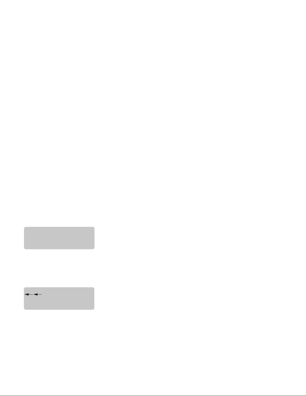
TROUBLESHOOTING
OVERFLOW CUP
FULL. EMPTY CUP
SERVER NOT
IN PLACE
A troubleshooting guide is provided to suggest probable causes and remedies for the most likely problems
encountered. If the problem remains after exhausting the troubleshooting steps, contact the Bunn-O-Matic
Technical Service Department.
• Inspection, testing, and repair of electrical equipment should be performed only by qualied
service personnel.
• All electronic components have 120 - 240 volt ac and low voltage dc potential on their terminals.
Shorting of terminals or the application of external voltages may result in board failure.
• Intermittent operation of electronic circuit boards is unlikely. Board failure will normally be per-
manent. If an intermittent condition is encountered, the cause will likely be a switch contact or
a loose connection at a terminal or crimp.
• Solenoid removal requires interrupting the water supply to the valve. Damage may result if sole-
noids are energized for more than ten minutes without a supply of water.
• The use of two wrenches is recommended whenever plumbing ttings are tightened or loosened.
This will help avoid twists and kinks in the tubing.
• Make certain that all plumbing connections are sealed and electrical connections tight and iso-
lated.
• This brewer is heated at all times. Keep away from combustibles.
WARNING
• Exercise extreme caution when servicing electrical equipment.
• Disconnect the brewer from the power source when servicing, except when electrical tests are
specified.
• Follow recommended service procedures.
• Replace all protective shields or safety notices.
Screen Displayed
Possible Cause
1. Overflow cup is full of water.
1. Soft Heat Server not correctly
positioned on base.
2. Not using a Soft Heat Server, and
the SERVER DETECT function is
activated (on).
Troubleshooting Procedure
Empty cup
Position the server so that the connector pins on the server make contact with connector on the brewer.
Disable the SERVER DETECT function. See page 32 for procedure.
Page 36
34025 022509
Page 37
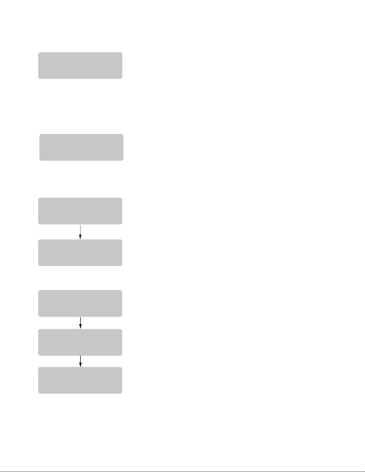
TROUBLESHOOTING (cont.)
NO FUNNEL
PRESENT
CHECK FUNNEL
FOR FRESH COFFEE
PRESS BREW
TO BREW ANYWAY
TEMPERATURE
TOO LOW
TO CANCEL
PRESS ON/OFF
TO FINISH:
PRESS BREW
BREW STOPPED!
FUNNEL REMOVED?
Screen Displayed
Possible Cause Troubleshooting Procedure
1. SMART FUNNEL not fully inserted
into the funnel rails.
2. Not using a SMART FUNNEL,
and the FUNNEL DETECT function
is activated (on).
1. Water temperature in the tank
does not meet the SET READY
TEMPERATURE.
1. Brew funnel was not removed
after the previous brew cycle was
finished.
Position the funnel so that the sensor
is directly beneath the sensor coil on
the brewer.
Disable the FUNNEL DETECT function. See page 31 for procedure.
(a) Wait for the brewer to heat to the
proper temperature.
(b) Disable the BREW LOCKOUT
function. See page 11 for procedure.
Remove funnel, check contents, and
insert back into the funnel rails.
OR
1. Brew funnel was moved out of
position after the brew cycle was
started.
Press BREW to start a brew cycle
without removing the funnel.
To resume brewing, correctly position the funnel and press BREW
again. The brew cycle will resume
from the point it was interrupted.
OR
Press ON/OFF to terminate the
cycle.
Page 37
34025 022509
Page 38
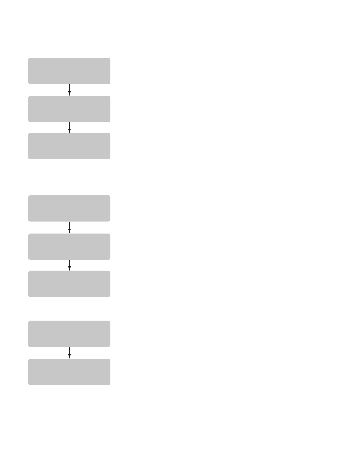
TROUBLESHOOTING (cont.)
TO CANCEL
PRESS ON/OFF
TO FINISH:
PRESS BREW
BREW STOPPED!
SERVER REMOVED?
TO CANCEL
PRESS ON/OFF
TO FINISH:
PRESS BREW
BREW STOPPED!
IS SWITCH OFF?
CHECK HEATING
CIRCUIT
HEATING TIME
TOO LONG
Screen Displayed
1. Soft Heat Server was moved out
of position after the brew cycle was
started.
1. ON/OFF switch was pressed after
the brew cycle was started.
Troubleshooting ProcedurePossible Cause
To resume brewing, correctly
position the Soft Heat Server and
press BREW again. The brew cycle
resumes from the point it was interrupted.
OR
Press ON/OFF to terminate the brew
cycle.
To resume brewing, press BREW
again. The brew cycle resumes form
the point it was interrupted.
1. Tank Heater failure
2. Triac Failure
3. Control Board/Thermistor failure
OR
Press ON/OFF to terminate the brew
cycle.
Service Required
Service Required
Service Required
Page 38
34025 022509
Page 39
TROUBLESHOOTING (cont.)
CHECK WATER
SUPPLY
FILL TIME TOO
LONG
CHECK FOR BAD
CONNECTIONS
TEMP SENSOR
OUT OF RANGE
CHECK WIRE FOR
SHORTS
TEMP SENSOR
OUT OF RANGE
Screen Displayed
1. Water shut off to brewer
2. Inlet Solenoid Valve failure
3. Control Board Failure
1. Temperature Sensor Probe wire(s)
broken or not making connection.
Troubleshooting ProcedurePossible Cause
Check water supply shut-off
Service required
Service required
Check wire and connection of both
black and white wires of temperature
probe.
1. Temperature Sensor Probe
wire(s) shorted to housing, or to
each other.
Check to confirm that wire(s) are
not pinched between two surfaces
or connected to each other.
Page 39
34025 022509
Page 40

TROUBLESHOOTING (cont.)
Problem
Equipment will not operate.
Brew cycle will not start.
Possible Cause
1. No power or incorrect voltage.
1. No water
2. ON/OFF switch
3. Brew switch
4. Brew Valve
5. Electronic Control Board
Troubleshooting Procedure
Measure the voltage at the terminal
block and confirm that it matches the
voltage specified on the brewer data
plate within +/- 10%.
Check plumbing and shut-off valves
Test the ON/OFF switch. Refer to the
switch test procedures on page 33
Test the BREW switch. Refer to the
switch test procedures on page 33
Test the Brew valve. Refer to Testing
Individual Components on page 33.
Substitute a control board known to
be in good working order.
Automatic refill will not operate
or display shows FILL TIME TOO
LONG
1. No water
2. Water strainer/flow control
(.750 GPM)
Check plumbing and shut-off valves.
(A) Direction of flow arrow must be
pointing towards direction of water
flow.
(B) Remove the strainer/flow control
and check for obstructions. Clear or
replace.
Page 40
34025 022509
Page 41

TROUBLESHOOTING (cont.)
Problem
Automatic refill will not operate or
display shows FILL TIME TOO LONG
(cont.)
Possible Cause
3. Refill Probe or Sensitivity Setting
Troubleshooting Procedure
Check the sensitivity setting. Refer
to the Refill function on page 28.
If the left three digit number is less
than the right number, the machine
“thinks” it is full and the refill valve
should be off. If the left number is
larger than the right, then the refill
valve will automatically be turned
on to fill the tank. The right number
is the threshold setting and can be
adjusted to compensate for extreme
water conditions: very pure, low
conductance water requires a higher
setting, while high mineral content,
high conductance water requires
a lower setting. Note that the left
number changes from a high value
when water is NOT touching the refill
probe to a low value when water IS
touching the probe. For best operation, the right number should be set
to a value midway between these low
and high numbers. Before changing
the setting, confirm that the refill
probe is free of scale buildup and the
connection to it is secure.
Water flows into tank continuously
with power removed from brewer.
4. Refill Valve
5. Overflow Protection Switch
6. Electronic Control Board
1. Refill valve
Page 41
Test the Refill valve. Refer to Testing
Individual Components on page 33.
When this condition occurs, the
brewer will display OVERFLOW CUP
FULL. EMPTY CUP. The reason for
overfilling could be a defective refill
valve, an incorrect sensitivity setting,
(see above) or boiling.
Substitute a control board known to
be in good working order.
Foreign material lodged in valve,
holding it in open state.
34025 022509
Page 42

TROUBLESHOOTING (cont.)
Problem
Possible Cause
Troubleshooting Procedures
Water flows into tank continuously
with power applied to brewer.
1. Refill Probe or Sensitivity Setting
Check the sensitivity setting. Refer
to the Refill function on page 28. If
the left three digit number is less
than the right number, the machine
“thinks” it is full and the refill valve
should be off. If the left number is
larger than the right, then the refill
valve will automatically be turned
on to fill the tank. The right number
is the threshold setting and can be
adjusted to compensate for extreme
water conditions: very pure, low
conductance water requires a higher
setting, while high mineral content,
high conductance water requires
a lower setting. Note that the left
number changes from a high value
when water is NOT touching the refill
probe to a low value when water IS
touching the probe. For best operation, the right number should be set
to a value midway between these low
and high numbers. Before changing
the setting, confirm that the refill
probe is free of scale buildup and
the connection to it is secure.
Water will not heat or display shows
HEATING TIME TOO LONG
2. Electronic Control Board
1. Limit Thermostat
CAUTION - Do not eliminate or
bypass limit thermostat. Use only
replacement part #23717.0001.
2. Tank Heaters
Page 42
Substitute a control board known to
be in good working order.
Remove power from the brewer.
Press reset button on limit thermostat. Then check for continuity
through it.
Remove power from the brewer.
Check for continuity through the
tank heaters.
34025 022509
Page 43

TROUBLESHOOTING (cont.)
Problem
Possible Cause
Troubleshooting Procedures
Water will not heat or display shows
HEATING TIME TOO LONG (cont.)
3. Triac
4. Electronic Control Board
Remove power from the brewer.
Connect a voltmeter across one of
the tank heaters. Reapply power
to the brewer and refer to Testing
Individual Components on page 33.
If the full supply voltage is measured
when the tank heater is turned on,
and zero voltage is measured with
the triac off, then the triac is good. If
half the supply voltage is measured,
the triac is defective. If very low, or
zero voltage is measured, there could
be a defective triac or a defective
control board.
Perform the above procedure for
testing triacs. If the voltage measured is very low or zero, then
substitute a control board known to
be in good working order.
Spitting or unusual steaming from
sprayhead or air vents. (Water too
hot)
1. Triac
2. Lime Buildup
CAUTION - Tank and tank components should be delimed regularly
depending on local water conditions. Excessive mineral buildup on
stainless steel surfaces can initiate
corrosive reactions resulting in serious leaks.
Remove power from the brewer.
Connect a voltmeter across one of
the tank heaters. Reapply power
to the brewer and refer to Testing
Individual Components on page 33.
If the full supply voltage is measured
when the tank heater is turned on,
and zero voltage is measured with
the triac off, then the triac is good. If
half the supply voltage is measured,
the triac is defective. If very low, or
zero voltage is measured, there could
be a defective triac or a defective
control board.
Inspect the tank assembly for excessive lime deposits. Delime as
required.
Page 43
34025 022509
Page 44

TROUBLESHOOTING (cont.)
Problem
Spitting or unusual steaming from
sprayhead or air vents. (Water too
hot) (cont.)
Inconsistent beverage level in
server.
Possible Cause
3. Electronic control board
1. Strainer/flow control (.750 GPM)
2. Improper water pressure
3. Brew Valve
Troubleshooting Procedures
Perform the above procedure for
testing triacs. If the voltage measured is very low or zero, then
substitute a control board known to
be in good working order.
(A) Direction of flow arrow must be
pointing towards the brewer.
(B) Remove the strainer/flow control
and check for obstructions. Clear or
replace.
Check operating water pressure to
the brewer. It must be between 20
and 90 psi (138 and 620 kPa).
Test the Brew Valve. Refer to Testing
Individual Components on page 33.
Turn the valve on for 30 seconds and
collect the water dispensed from the
sprayhead. Repeat the test several
times to confirm a consistent volume
of dispensed water. If not consistent,
check the valve, tubing and sprayhead for lime buildup.
4. Bypass Valve
5. Lime buildup
Page 44
If bypass is being used on the
inconsistent brewing recipe, test
the Bypass Valve. Refer to Testing
Individual Components on page 33.
Turn the valve on for 30 seconds
and collect the water collected
from the bypass opening. Repeat
the test several times to confirm
a consistent volume of dispensed
water. If not consistent, check the
valve, tubing and bypass opening
for lime buildup.
Inspect for lime buildup that could
block the tank, tank fittings, tubing,
valves and sprayhead.
34025 022509
Page 45

TROUBLESHOOTING (cont.)
Problem Possible Cause
Consistently high or low beverage
1. Brew Volume adjustment
level in server.
Dripping from sprayhead.
Water overflows filter.
1. Brew Valve
1. Type of paper filters
2. No sprayhead
Beverage overflows server.
1. Beverage left in server from previous brew
2. Brew Volume adjustment
Troubleshooting Procedures
Adjust the brew volume as required
to achieve the recommended volume
for each brew cycle.
Repair or replace leaky valve.
BUNN paper filters should be used
for proper extraction.
Check sprayhead
The brew cycle should be started
only with an empty server under
the funnel.
Adjust the brew volume as required
to achieve the recommended volume
for each brew cycle.
Weak beverage.
1. Type of paper filters
2. Coffee
3. Sprayhead
4. Funnel Loading
5. Water temperature
BUNN paper filters should be used
for proper extraction.
A sufficient quantity of fresh drip
or regular grind should be used for
proper extraction.
A clean sprayhead should be used
to properly wet the bed of ground
coffee in the funnel.
The BUNN paper filter should be
centered in the funnel and the bed
of ground coffee leveled by gentle
shaking.
Empty the server, remove its cover,
and place the server beneath the
sprayhead. Place empty funnel over
the server entrance, with ON/OFF
switch in the "ON" position press
the start switch and release it. Check
the water temperature immediately
below the sprayhead with a thermometer. The reading should not
be less than 195˚F(91˚C).
Page 45
34025 012004
Page 46

TROUBLESHOOTING (cont.)
Problem
Weak beverage (cont.)
Brewer is making unusual noises.
Possible Cause Troubleshooting Procedures
6. Incorrect Recipe
Consider adjusting bypass percentage, preinfusion, or pulse brew.
Contact Bunn-O-Matic for suggestions.
1. Solenoid (Inlet)
The nut on back of the solenoid
must be tight or it will vibrate during
operation
2. Plumbing lines
Plumbing lines should not be resting
on the counter top.
3. Water Supply
(A) The brewer must be connected
to a cold water line.
(B) Water pressure to the brewer
must not be higher than 90 psi (620
kPa). Install a regulator if necessary
to lower the working pressure to approximately 50 psi (345 kPa).
4. Tank Heaters.
Remove and clean lime off tank
heaters.
Page 46
34025 100501
Page 47
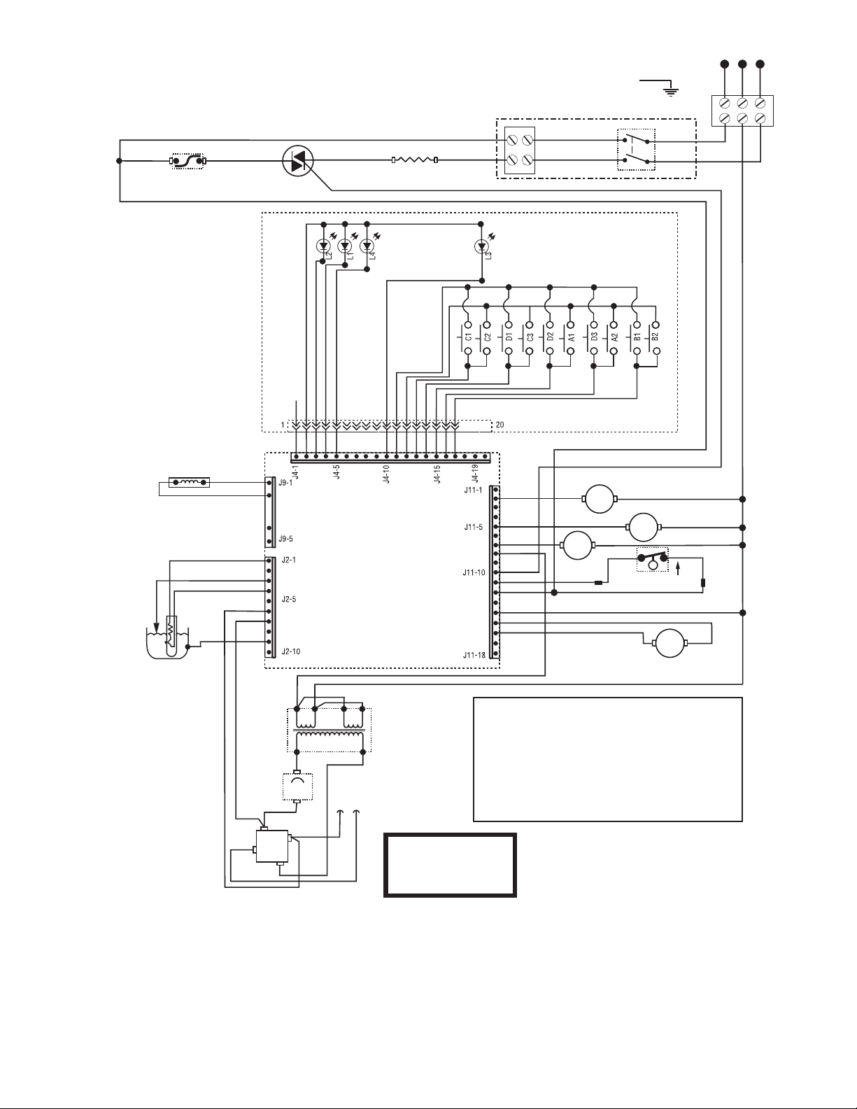
LIMIT THERMOSTAT
TRIAC
TANK HEATER
SOL
SOL
SOL
SOL
BREW
BYPASS
REFILL
WHI
WHI
WHI
WHI
WHI
MT 1 BLU -14
BLK-14 BLK-14
RED
N.C.
RED
OVERFLOW
PROTECTION SWITCH
FUNNEL LOCK
(OPTIONAL)
+
–
AC
AC
RECTIFIER
4
AMP
24VDC
+
–
WHI
BLK
BLU/BLK
BLK
BLU/BLK
RED
120/208 OR 120/240
VOLT A.C. + GND
SINGLE PHASE
32043.0000D 01/07 © 2000 BUNN-O-MATIC CORPORATION
SCHEMATIC WIRING DIAGRAM
SINGLE SH with SMART FUNNEL (DBC)
MT2
SERVER
TRANSFORMER
BRN/BLK
BRN/WHI
BLK
YEL
TAN
WHI
WHI/VIO
GRY
WHI/GRN
VIO
SWITCH UNIT ASSY
SHIELD
FUNNEL SENSOR
CONTROL PC BOARD
WATER LEVEL
PROBE
TEMP
PROBE
VIO
WHI/VIO
WHI
PNK
BLK
BLK
GRN
WHI/RED
Touch Switch Assembly Codes
A1 Brew
A2 On/Off
B1 "Hidden" Left
B2 "Hidden" Right
C1 Large Batch
C2 Medium Batch
C3 Small Batch
D1 "Digital" Left Hidden Button
D2 "Brewer" Center Hidden Button
D3 "Control" Right Hidden Button
L1 Large Batch LED
L2 Medium Batch LED
L3 Small Batch LED
L4 On/Off LED
LED's
GRN
RED-14
BLK-14
N
L1
BLK-14
RED-14
RED-14
BLK-14
MODELS WITH MAIN ON/OFF SWITCH ONLY
WHI
WHI
L2
RED
BLK
Page 47
34025 022509
Page 48
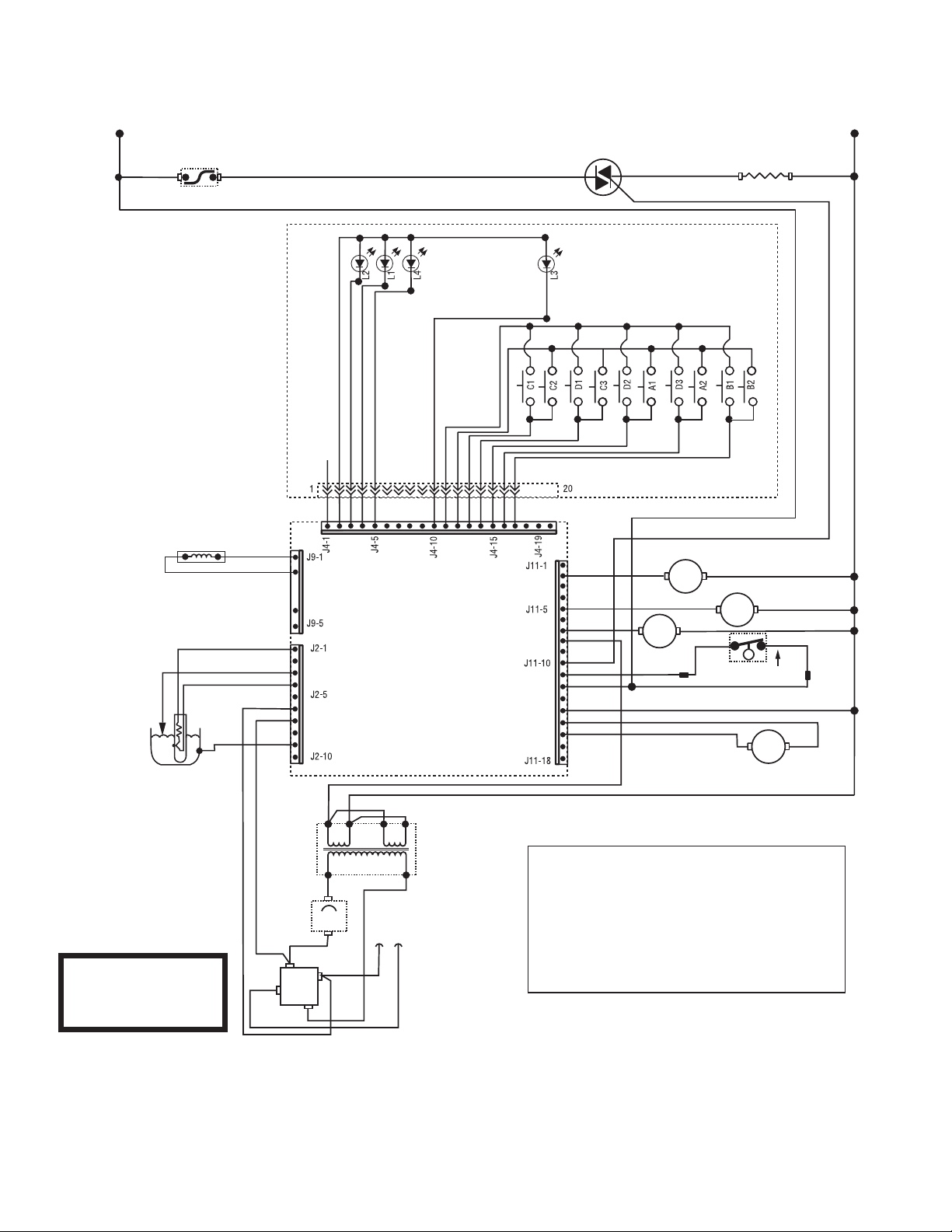
LIMIT THERMOSTAT
TRIAC
TANK HEATER
SOL
SOL
SOL
SOL
BREW
BYPASS
REFILL
WHI
WHI-14
WHI
WHI
WHI
WHI
W
H
I
L1
N
MT 1 BLU -14
BLK-14 BLK-14
RED
N.C.
RED
OVERFLOW
PROTECTION SWITCH
FUNNEL LOCK
(OPTIONAL)
+
–
AC
AC
RECTIFIER
4
AMP
24VDC
+
–
WHI
BLK
BLU/BLK
BLK
BLU/BLK
RED
120 VOLT A.C.
2 - WIRE
SINGLE PHASE
SCHEMATIC WIRING DIAGRAM
SINGLE SH DBC with SMART FUNNEL
MT2
SERVER
TRANSFORMER
B
L
K
BRN/BLK
BRN/WHI
BLK
YEL
TAN
WHI
WHI/VIO
GRY
WHI/GRN
VIO
SWITCH UNIT ASSY
SHIELD
FUNNEL SENSOR
CONTROL PC BOARD
WATER LEVEL
PROBE
TEMP
PROBE
VIO
WHI/VIO
WHI
PNK
BLK
BLK
GRN
WHI/RED
Touch Switch Assembly Codes
A1 Brew
A2 On/Off
B1 "Hidden" Left
B2 "Hidden" Right
C1 Large Batch
C2 Medium Batch
C3 Small Batch
D1 "Digital" Left Hidden Button
D2 "Brewer" Center Hidden Button
D3 "Control" Right Hidden Button
L1 Large Batch LED
L2 Medium Batch LED
L3 Small Batch LED
L4 On/Off LED
LED's
Page 48
Page 49
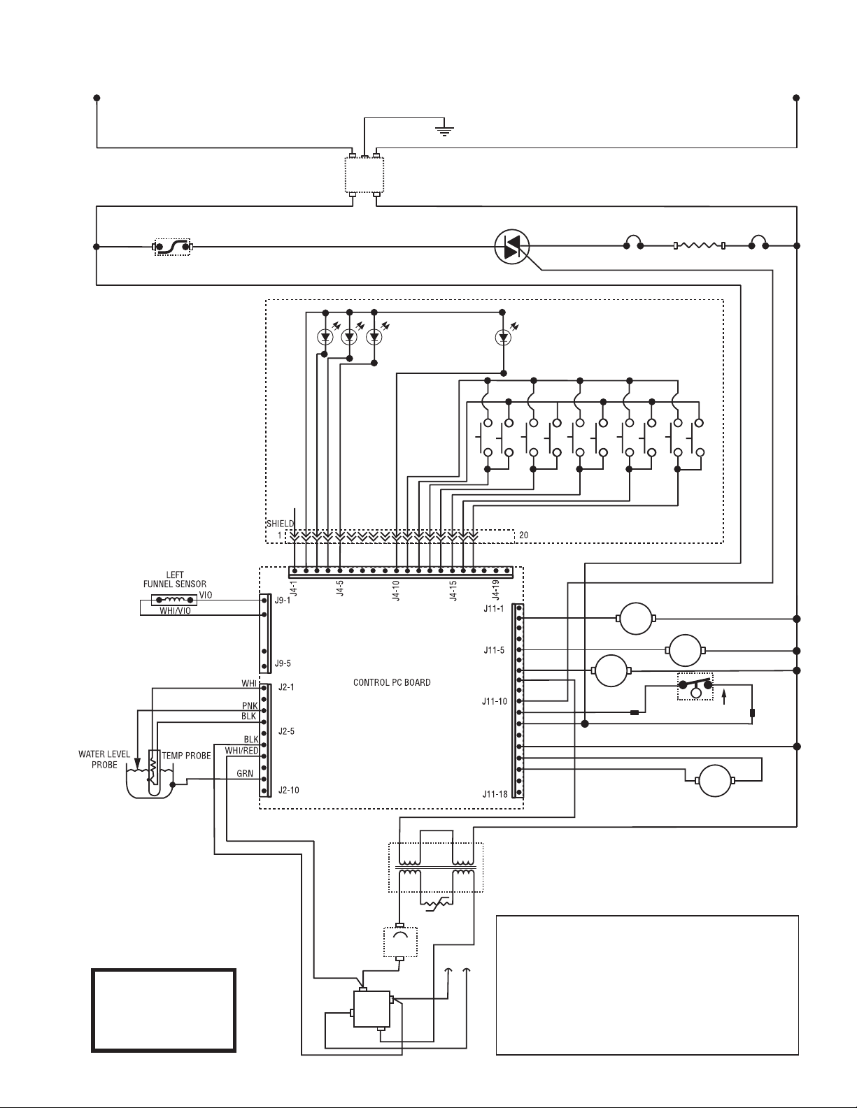
LIMIT THERMOSTAT
TRIAC
TANK HEATER
SOL
SOL
SOL
SOL
BREW
BYPASS
REFILL
WHI
WHI
MT 1 BLU -14
BLK-14
BLK-14
RED
N.C.
RED
OVERFLOW
PROTECTION SWITCH
FUNNEL LOCK
(OPTIONAL)
+
–
AC
AC
RECTIFIER
4
AMP
24VDC
+
–
BLK
BLU/BLK
BLK
BLU/BLK
RED
230 VOLT AC
2 WIRE
SINGLE PHASE
50HZ
MT2
SERVER
TRANSFORMER
BRN/BLK
BRN/WHI
BLK
YEL
TAN
WHI/VIO
GRY
WHI/GRN
VIO
THERMAL
SAFETY FUSE
THERMAL
SAFETY FUSE
RED
RED
RED RED
RED
RESETTABLE
FUSE
BLK
SCHEMATIC WIRING DIAGRAM
SINGLE SH DBC (W/SMART FUNNEL)
L2
L1
RED
RED
EMI
FILTER
GRN/YEL
BLK
BLK
Touch Switch Assembly Codes
A1 Brew
A2 On/Off
B1 "Hidden" Left
B2 "Hidden" Right
C1 Large Batch
C2 Medium Batch
C3 Small Batch
D1 "Digital" Left Hidden Button
D2 "Brewer" Center Hidden Button
D3 "Control" Right Hidden Button
L1 Large Batch LED
L2 Medium Batch LED
L3 Small Batch LED
L4 On/Off LED
LED's
C1 D1 A1 B1 B2 A2 D2 D3 C2 C3
L3
L4 L1 L2
TOUCH SWITCH ASSMBLE
Page 49
Page 50
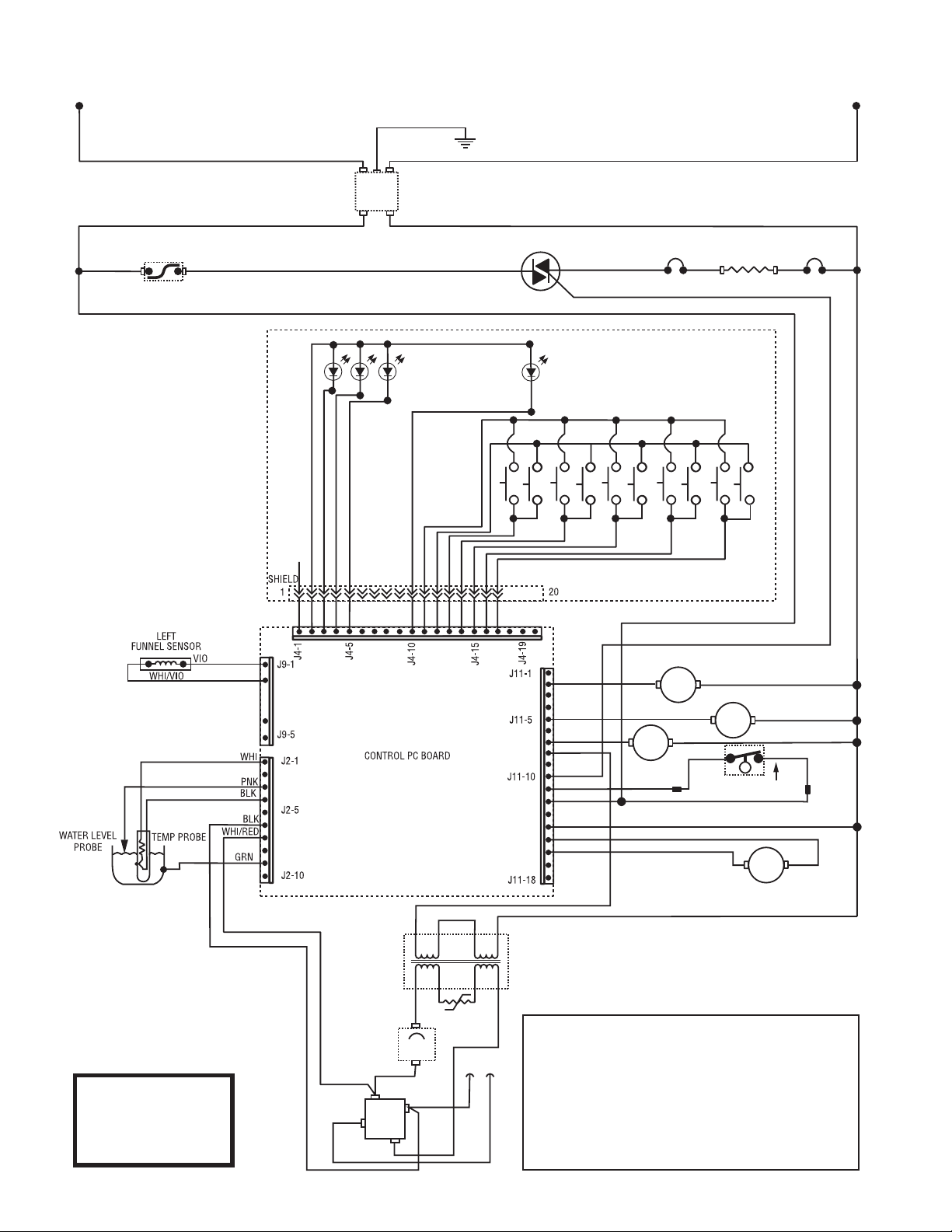
LIMIT THERMOSTAT
TRIAC
TANK HEATER
SOL
SOL
SOL
SOL
BREW
BYPASS
REFILL
WHI
WHI
MT 1 BLU -14
BLK-14
BLK-14
RED
N.C.
RED
OVERFLOW
PROTECTION SWITCH
FUNNEL LOCK
(OPTIONAL)
+
–
AC
AC
RECTIFIER
4
AMP
24VDC
+
–
BLK
BLU/BLK
BLK
BLU/BLK
RED
200 VOLT AC
2 WIRE
SINGLE PHASE
50/60HZ
MT2
SERVER
TRANSFORMER
BRN/BLK
BRN/WHI
BLK
YEL
TAN
WHI/VIO
GRY
WHI/GRN
VIO
THERMAL
SAFETY FUSE
THERMAL
SAFETY FUSE
RED
RED
RED RED
RED
RESETTABLE
FUSE
BLK
SCHEMATIC WIRING DIAGRAM
SINGLE SH DBC (W/SMART FUNNEL)
L2
L1
RED
RED
EMI
FILTER
GRN/YEL
BLK
BLK
Touch Switch Assembly Codes
A1 Brew
A2 On/Off
B1 "Hidden" Left
B2 "Hidden" Right
C1 Large Batch
C2 Medium Batch
C3 Small Batch
D1 "Digital" Left Hidden Button
D2 "Brewer" Center Hidden Button
D3 "Control" Right Hidden Button
L1 Large Batch LED
L2 Medium Batch LED
L3 Small Batch LED
L4 On/Off LED
LED's
C1 D1 A1 B1 B2 A2 D2 D3 C2 C3
L3
L4 L1 L2
TOUCH SWITCH ASSMBLE
Page 50
 Loading...