

Page 1
INSTALLATION & OPERATING GUIDE
BUNN-O-MATIC CORPORATION
POST OFFICE BOX 3227
SPRINGFIELD, ILLINOIS 62708-3227
PHONE: (217) 529-6601 FAX: (217) 529-6644
To ensure you have the latest revision of the Operating Manual, or to view the Illustrated Parts
Catalog, Programming Manual, or Service Manual, please visit the Bunn-O-Matic website, at
www.bunn.com. This is absolutely FREE, and the quickest way to obtain the latest catalog and
manual updates. For Technical Service, contact Bunn-O-Matic Corporation at 1-800-286-6070.
41167.0001A 08/10 ©2008 Bunn-O-Matic Corporation
Page 2

BUNN-O-MATIC COMMERCIAL PRODUCT WARRANTY
Bunn-O-Matic Corp. (“BUNN”) warrants equipment manufactured by it as follows:
1) All equipment other than as specified below: 2 years parts and 1 year labor.
2) Electronic circuit and/or control boards: parts and labor for 3 years.
3) Compressors on refrigeration equipment: 5 years parts and 1 year labor.
4) Grinding burrs on coffee grinding equipment to grind coffee to meet original factory screen sieve analysis:
parts and labor for 3 years or 30,000 pounds of coffee, whichever comes first.
These warranty periods run from the date of installation BUNN warrants that the equipment manufactured by
it will be commercially free of defects in material and workmanship existing at the time of manufacture and
appearing within the applicable warranty period. This warranty does not apply to any equipment, component or
part that was not manufactured by BUNN or that, in BUNN’s judgment, has been affected by misuse, neglect,
alteration, improper installation or operation, improper maintenance or repair, damage or casualty. This warranty is
conditioned on the Buyer 1) giving BUNN prompt notice of any claim to be made under this warranty by telephone
at (217) 529-6601 or by writing to Post Office Box 3227, Springfield, Illinois 62708-3227; 2) if requested by
BUNN, shipping the defective equipment prepaid to an authorized BUNN service location; and 3) receiving prior
authorization from BUNN that the defective equipment is under warranty.
THE FOREGOING WARRANTY IS EXCLUSIVE AND IS IN LIEU OF ANY OTHER WARRANTY, WRITTEN OR
ORAL, EXPRESS OR IMPLIED, INCLUDING, BUT NOT LIMITED TO, ANY IMPLIED WARRANTY OF EITHER
MERCHANTABILITY OR FITNESS FOR A PARTICULAR PURPOSE. The agents, dealers or employees of BUNN
are not authorized to make modifications to this warranty or to make additional warranties that are binding on
BUNN. Accordingly, statements by such individuals, whether oral or written, do not constitute warranties and
should not be relied upon.
If BUNN determines in its sole discretion that the equipment does not conform to the warranty, BUNN, at its
exclusive option while the equipment is under warranty, shall either 1) provide at no charge replacement parts
and/or labor (during the applicable parts and labor warranty periods specified above) to repair the defective
components, provided that this repair is done by a BUNN Authorized Service Representative; or 2) shall replace
the equipment or refund the purchase price for the equipment.
THE BUYER’S REMEDY AGAINST BUNN FOR THE BREACH OF ANY OBLIGATION ARISING OUT OF THE SALE OF
THIS EQUIPMENT, WHETHER DERIVED FROM WARRANTY OR OTHERWISE, SHALL BE LIMITED, AT BUNN’S
SOLE OPTION AS SPECIFIED HEREIN, TO REPAIR, REPLACEMENT OR REFUND.
In no event shall BUNN be liable for any other damage or loss, including, but not limited to, lost profits, lost sales,
loss of use of equipment, claims of Buyer’s customers, cost of capital, cost of down time, cost of substitute
equipment, facilities or services, or any other special, incidental or consequential damages.
392, AutoPOD, AXIOM, BrewLOGIC, BrewMETER, Brew Better Not Bitter, BrewWISE, BrewWIZARD, BUNN
Espress, BUNN Family Gourmet, BUNN Gourmet, BUNN Pour-O-Matic, BUNN, BUNN with the stylized red line,
BUNNlink, Bunn-OMatic, Bunn-O-Matic, BUNNserve, BUNNSERVE with the stylized wrench design, Cool Froth,
DBC, Dr. Brew stylized Dr. design, Dual, Easy Pour, EasyClear, EasyGard, FlavorGard, Gourmet Ice, Gourmet
Juice, High Intensity, iMIX, Infusion Series, Intellisteam, My Café, PowerLogic, Quality Beverage Equipment
Worldwide, Respect Earth, Respect Earth with the stylized leaf and coffee cherry design, Safety-Fresh, savemycoffee.com, Scale-Pro, Silver Series, Single, Smart Funnel, Smart Hopper, SmartWAVE, Soft Heat, SplashGard,
The Mark of Quality in Beverage Equipment Worldwide, ThermoFresh, A Partner You Can Count On, Air Brew,
Air Infusion, Beverage Bar Creator, Beverage Profit Calculator, Brew better, not bitter., BUNNSource, Coffee At
Its Best, Cyclonic Heating System, Digital Brewer Control, Nothing Brews Like a BUNN, Pouring Profits, Signature Series, Tea At Its Best, Phase Brew, The Horizontal Red Line, Titan, trifecta, Ultra, Velocity Brew are either
trademarks or registered trademarks of Bunn-O-Matic Corporation.
Page 2
41167.1 051910
Page 3
CONTENTS
Warranty .............................................................................................................2
Introduction ........................................................................................................3
User Notices .......................................................................................................3
Electrical Requirements ......................................................................................4
Plumbing Requirements .....................................................................................5
Initial Setup .........................................................................................................6
Operation ............................................................................................................7
Cleaning ..............................................................................................................8
Tank Draining ......................................................................................................9
Programming ....................................................................................................10
INTRODUCTION
This equipment is factory set to brew approximately 6-8 ounces of coffee or tea into an awaiting dispenser.
It is only for indoor use on a sturdy counter or shelf. Replace any unreadable or damaged labels.
WARNING
• DO NOT OVERLOAD CIRCUIT.
• ALWAYS ELECTRICALLY GROUND
THE CHASSIS.
• DO NOT DEFORM PLUG OR CORD.
• FOLLOW NATIONAL AND LOCAL
ELECTRICAL CODES.
• KEEP COMBUSTIBLES AWAY.
FAILURE TO COMPLY RISKS EQUIPMENT
DAMAGE, FIRE OR SHOCK HAZARD.
READ THE ENTIRE
OPERATING MANUAL BEFORE
USING THIS PRODUCT
00986.0000F 10/07 ©1994 Bunn-O-Matic Corporation
#00986.0000
USER NOTICES
As directed in the International Plumbing Code of the
International Code Council and the Food Code
Manual of the Food and Drug Administration (FDA),
this equipment must be installed with adequate
backflow prevention to comply with federal, state
and local codes. For models installed outside the
U.S.A., you must comply with the applicable Plumbing /Sanitation Code for your area.
#00656.0001
#00824.0000
Keep hands clear
during brew cycle.
HOT liquids can burn.
#41177.0001
To reduce the risk of electric shock,
do not remove or open cover.
No user-serviceable parts inside.
#37881.0002
Keep hands clear
when closing brew chamber.
Moving parts can pinch.
Authorized service personnel only.
Disconnect power before servicing.
Page 3
41167.1 051508
Page 4
ELECTRICAL REQUIREMENTS
CAUTION - The brewer must be disconnected from the power source until specified in Initial Set-Up.
Refer to Data Plate on the Brewer, and local/national electrical codes to determine circuit requirements.
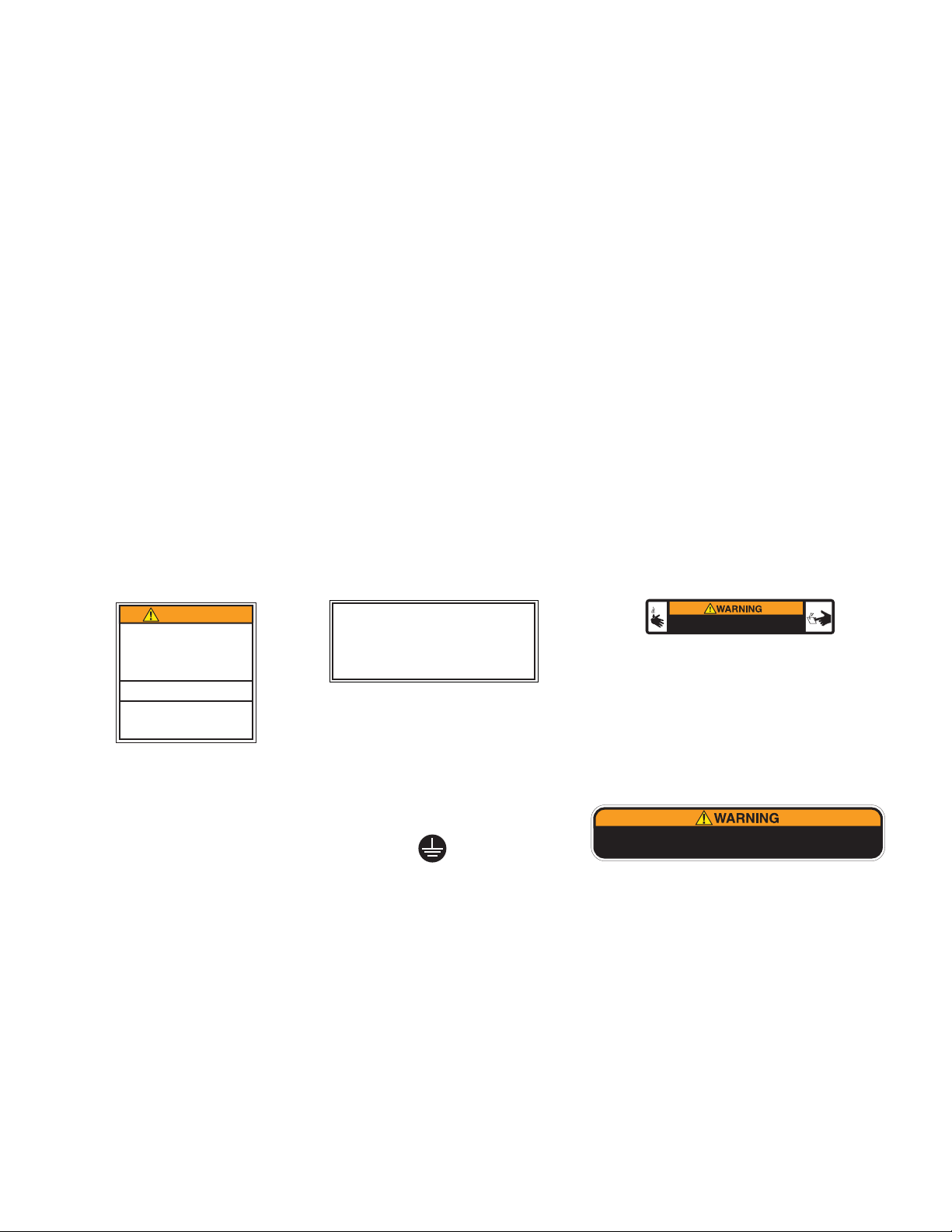
120 VOLT Model
230 VOLT CE Model
230 VOLT UK Model
Note: This electrical service consists of 2 current carrying conductors (L1 and Neutral) and a separate con-
ductor for chassis ground.
Electrical Hook-Up
CAUTION – Improper electrical installation will damage electronic components.
1. An electrician must provide electrical service as specified.
2. Using a voltmeter, check the voltage and color coding of each conductor at the electrical source.
3. If plumbing is to be hooked up later be sure the brewer is disconnected from the power source. If plumbing
has been hooked up, the brewer is ready for Initial Set-Up.
CE REQUIREMENTS
• This appliance must be installed in locations where it can be overseen by trained personnel.
• For proper operation, this appliance must be installed where the temperature is between 5°C to 35°C.
• Appliance shall not be tilted more than 10° for safe operation.
• An electrician must provide electrical service as specified in conformance with all local and national codes.
• This appliance must not be cleaned by water jet.
• This appliance is not intended for use by persons (including children) with reduced physical, sensory or mental
capabilities, or lack of experience and knowledge, unless they have been given instructions concerning use of
this appliance by a person responsible for its safety.
• Children should be supervised to ensure they do not play with the appliance.
• If the power cord is ever damaged, it must be replaced by the manufacturer or authorized service personnel with
a special cord available from the manufacturer or its authorized service personnel in order to avoid a hazard.
• Machine must not be immersed for cleaning.
Page 4
41167.1 031710
Page 5
PLUMBING REQUIREMENTS
These brewers must be connected to a cold water system with operating pressure between 20 and 90 psi
(138 and 620 kPa) from a ½˝ or larger supply line. A shut-off valve should be installed in the line before the
brewer. Install a regulator in the line when pressure is greater than 90 psi (620 kPa) to reduce it to 50 psi (345
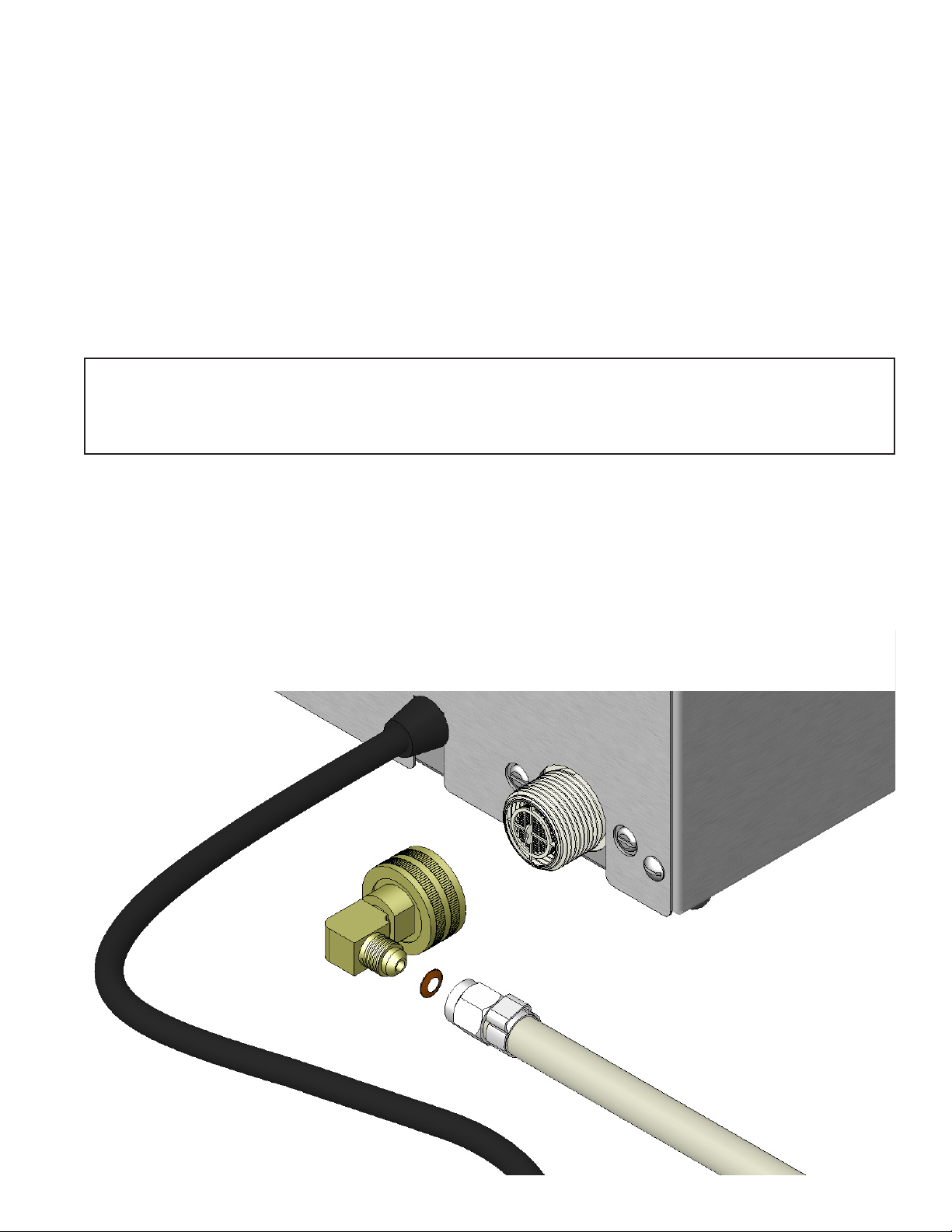
kPa). The water inlet fitting is .75-11.5 NH (HOSE THREAD). For convenience an elbow adaptor is provided
to convert to a ¼˝ flare fitting. Bunn-O-Matic does not recommend the use of a reverse-osmosis or deionized
water supply to this equipment.
NOTE - Bunn-O-Matic recommends ¼˝ copper tubing for installations of less than 25 feet and 3⁄8" for more than
25 feet from the ½˝ water supply line. A tight coil of tubing in the water line will facilitate moving the brewer to
clean the countertop. Bunn-O-Matic does not recommend the use of a saddle valve to install the brewer. The
size and shape of the hole made in the supply line by this type of device may restrict water flow.
As directed in the International Plumbing Code of the International Code Council and the Food Code Manual
of the Food and Drug Administration (FDA), this equipment must be installed with adequate backflow prevention to comply with federal, state and local codes. For models installed outside the U.S.A., you must
comply with the applicable Plumbing /Sanitation Code for your area.
NOTE - If a backflow preventer is required by code, a shock arrestor should be installed between backflow pre-
venter and dispenser. Installing the shock arrestor as close to the dispenser as possible will provide the best
results.
Plumbing Hook-Up
1. Flush the water line.
2. Securely attach the adaptor elbow assembly to the ¼˝ water supply line.
3. Securely attach adaptor elbow assembly to the the .75-11.5 NH (HOSE THREAD) fitting at the rear of the
brewer.
4. Turn on the water supply.
Page 5
41167.1 060910
Page 6

-1000 213.8 101.0 200 93.3
-500 212.9 100.5 200 93.3
0 212.0 100.0 200 93.3
500 211.1 99.5 200 93.3
1000 210.2 99.0 200 93.3
1500 209.3 98.5 200 93.3
2000 208.4 98.0 200 93.3
2500 207.4 97.4 200 93.3
3000 206.5 96.9 199 92.8
3500 205.6 96.4 198 92.2
4000 204.7 95.9 197 91.7
4500 203.8 95.4 196 91.1
5000 202.9 94.9 195 90.6
5500 201.9 94.4 195 90.6
6000 201.0 93.9 194 90.0
6500 200.1 93.4 193 89.4
7000 199.2 92.9 192 88.9
7500 198.3 92.4 191 88.3
8000 197.4 91.9 190 87.8
8500 196.5 91.4 189 87.2
9000 195.5 90.8 188 86.7
9500 194.6 90.3 187 86.1
10000 193.7 89.8 186 85.6
Brew water temperature is factory set at 200° F (93.3° C)
Areas of high altitude will require lowering this temperature to prevent boiling. This chart should be used as a
guide when readjusting the brew water temperature.
Altitude
(Feet)
Boiling point
of water
° F ° C
Recommended
water temperature
° F ° C
INITIAL SET-UP
1. Place a large empty cup under the brew chamber.
2. Connect the brewer to the power source.
3. Water will flow into the Hot Water tank and stop when
the tank is filled to its capacity.
4. Open, then close door with switch (See illustration)
5. Press the Large Brew Switch. Water will flow into the
Brew tank. Some excess water will flow into the cup.
5. Wait approximately ten minutes for the water in the tank
to heat to the proper temperature. Display will show
"HEATING" until tank reaches it's operating temperature.
Some water will drip from the brew chamber during
this time; this is due to expansion and should not occur
thereafter.
6. Water volumes and flow settings have been preset at the
factory. Refer to adjustments for the Set Brew Volumes
section of this manual should the volume need to be
increased or decreased.
7. The brewer is now ready for use in accordance with the
instructions for Coffee Brewing.
This is used to open
or close the pod
Preset but can be
OPEN/CLOSE
holder door.
LARGE BREW
adjusted.
OPERATING CONTROLS
Page 6
HOT WATER
Push and hold for dis-
pensing hot water only
(Max 10 oz).
SMALL BREW
Preset but can be ad-
justed.
41167.1 051508
Page 7

OPERATION
COFFEE BREWING
1. Place cup under brew chamber FIG 8-1. (Slide booster out for small cups) FIG 8-3.
2. Press the OPEN/CLOSE switch to open pod door FIG 8-2.
3. Press fresh pod firmly down into pod holder FIG 8-3.
4. Press the OPEN/CLOSE switch to close pod door FIG 8-2.
5. Press the desired brew switch.
6. Once the brew cycle is finished, display will read "BREWING COMPLETE", remove cup after display returns
to main screen.
FIG 8-1
FIG 8-4
HOT WATER DISPENSING
1. Place cup under brew chamber FIG 8-1. (Slide booster
out for small cups) FIG 8-3.
2. Press and hold the HOT WATER switch to fill. FIG
8-4 NOTE: Maximum of 10 oz.
POD INSERTED
FIG 8-2
Page 7
BOOSTER
FIG 8-3
41167.1 041410
Page 8

CLEANING
SPRAYHEAD
1. Open the pod door with the "OPEN/CLOSE" switch.
2. Disconnect brewer from power source and allow to cool.
3. Unscrew sprayhead counterclockwise (looking from below). Fig 8-1
4. Remove sprayhead and seal from holder.
5. Check and clean the sprayhead. The sprayhead holes must always remain open. Clean all the holes in the
plastic sprayhead to remove any mineral deposits. Wash and rinse in sink. Fig 8-2
6. When reassembling sprayhead, be sure to have seal installed with ridge facing up (A). Fig 8-3
BIN /DRIPTRAY
1. Pull the driptray assembly straight towards you.
2. Pull the bin straight out and empty as required.
3. Seperate the parts as shown in Fig 8-4 and wash
with mild, nonabrasive, liquid detergent.
4. Assembly is in reverse order.
REMOVE - CCW
INSTALL - CW
The use of a damp cloth rinsed in any mild, nonabrasive, liquid detergent is recommended for cleaning
all surfaces on Bunn-O-Matic equipment.
A
FIG 8-3
FIG 8-1
FIG 8-2
SHOWN UPSIDEDOWN
FOR CLARITY
Page 8
FIG 8-4
41167.1 051508
Page 9

TANK DRAINING
FACTORY BLOWOUT
1. Disconnect the power and water supply to brewer. Allow brewer to cool before proceeding.
2. Remove 2 screws that secure the top cover. Remove the cover. Place brewer next to a sink.
3. Disconnect the hose from (top) center hose barb of each tank. Connect a piece of ¼" ID hose (aproximately
12" long) in place of the ones you just removed. FIG. 9-1
4. Lay the brewer on it's back, with new hoses in sink.
5. Connect the brewer to the power source.
6. Press hidden switch until display reads "BREW LOCKOUT". Press and release until display reads "SERVICE
TOOLS?" Select "YES".
7. Display will read "TEST OUTPUTS?" Select "NO".
8. Display will read "FACTORY BLOWOUT?" Select "YES".
9. Select "START.
10. Turn brewer upside down over sink during this procedure! FIG. 9-2
11. When blowout mode will cycle on/off. Repeat cycle until no more water drains out. When tanks are empty
select "DONE".
12. Disconnect power to the brewer.
13. Remove your drain hoses and reconnect the original hoses.
14. Replace the top cover and tighten screws.
FIG 9-1
Page 9
FIG 9-2
41167.1 051508
Page 10

HIDDEN SWITCH
Press until display reads
"BREW LOCKOUT"
PROGRAMMING SWITCHES
HIDDEN SWITCH
Step forward through
screens
OPEN/CLOSE
"NO" or (-)
LARGE BREW (A)
"DONE"
Page 10
HOT WATER
"YES" or (+)
SMALL BREW (B)
Step backwards through
screens
41167.1 051508
Page 11

PROGRAM OVERVIEW
BREW LOCKOUT (YES/NO)
Setting to "YES" will only allow brews at or above the
"SET READY" temp screen.
BREW TYPE (A/B) (Tea/Coffee)
Tea setting provides less "purge" after brew cycle.
BREW OZ. (A/B) (1-16)
Adjust brew volume.
BREW METER (A/B) (1-5)
Simplified pulse brew adjustment.
1=Preinfusion. 2-5=pulse brew, 2 being the shortest
pulse brew cycle, 5 the longest pulse brew cycle.
ENTER SERVICE #
Program service phone number to be displayed anytime
there is a fault message.
ENTER PASSWORD
User must enter a 3 digit number to access remainder
of adjustments. If no number has been pre programmed
(0 0 0), then access is allowed.
SET PASSWORD (001-999)
Program any three digit number as a password.
SET LANGUAGE
Choose between English or Spanish.
UNITS
Choose between English or metric.
SET TEMP
Adjust tank temperature 185 to 205° F (85 to 96° C)
SET READY
Sets the minimum temperature allowable to start a brew
cycle. Range: (2° to 20° F) or (2° to 10° C) below the
set temperature.
ENTER ASSET #
This function allows the you to enter in an optional asset
number. This can be useful for tracking the usage or
service of an individual machine within a group.
SET PULSE BREW (A/B)
Individually adjust on/off times.
AIR TIME (A/B) (1-25)
Time the brew tank is purged at the end of each brew
cycle.
DRIP TIME (A/B) (OFF/1-50)
Time between brew cycle and pod ejection.
BREWS TO EMPTY (OFF/15-25)
Set number of used pods in bin to turn on "EMPTY
BIN" message.
ENABLE ENERGY SAVER
Choose to have the tank heaters turn off, or reduce the
tank temp to (140° F) or (60° C) once the "SET IDLE
TIME" has expired. .5-50.0 hrs.
AIR PUMP POWER (1-4)
Adjust air pressure for end of brew cycle purge.
BREW COUNTS
Retains the total number of brew cycles completed.
There is one reset-able counter, and one life counter
that is not reset-able.
CALIBRATE FLOW
Measure and enter the actual flow rate coming out of
the sprayhead.
SERVICE TOOLS
Diagnostic tool for troubleshooting purposes only
FACTORY DEFAULTS
Reset all brew settings, calibrations back to factory presets. Requires following "INITIAL SETUP" procedure.
Refer to the "PROGRAMMING MANUAL" at www.bunn.
com for more advanced programming information.
Page 11
41167.1 051508
Page 12

ADJUSTMENTS & OPTIONAL SETTINGS
BREW LOCKOUT ?
NO DONE YES
BREW METER A: 2
- +
BREW METER A: 2
- +
BREW TYPE A
TEA DONE COFFEE
BREW TYPE B
TEA DONE COFFEE
ENTER SERVICE #?
NO YES
BREW OZ A: 8.0
(-) DONE (+)
BREW OZ B: 6.0
(-) DONE (+)
ENTER PASSWORD
0 0 0
SET PASSWORD
0 0 0
SET TEMP: 200°
(-) DONE (+)
HOT H2O TEMP 200°
(-) DONE (+)
SET LANGUAGE ?
NO YES
SET READY: 195°
(-) DONE (+)
H2O READY: 190°
(-) DONE (+)
UNITS
METRIC DONE ENG
HOT H2O LOCKOUT ?
NO DONE YES
ENTER ASSET # ?
NO YES
Page 12
41167.1 011609
Page 13

ADJUSTMENTS & OPTIONAL SETTINGS (CONT.)
SetPulseBrew A ?
NO DONE YES
SetPulseBrew B ?
NO DONE YES
BREWS TO EMPTY
(-) 25 (+)
AIR TIME A: 17.0
(-) DONE (+)
AIR TIME B: 17.0
(-) DONE (+)
Enabl EnergySavr
NO DONE YES
DRIP T I M E A: 5
(-) DONE (+)
DRIP T I M E B: 5
(-) DONE (+)
AIR PUMP POWER 4
(-) DONE (+)
BREW COUNT ##
NO YES
CalibrateMaximum
NO H2O TIME? YES
SERVICE TOOLS ?
NO YES
BREW COUNT ##
RESET NEXT
NUMBER OF EJECTS
SINGLE DOUBLE
FACTORY DEFAULTS
NO YES
CALIBRATE FLOW ?
NO YES
SEAL REPLACED ?
NO YES
AutoPOD BREWER
VERSION xx.xx
Page 13
41167.1 011609
Page 14

SCHEMATIC WIRING DIAGRAM AUTOPOD
BIN
LEVEL PROBE
MAGNET
INDEX SENSOR
PRESSURE SW
NO
NC
FLOW METER
C
(SIG)
(GND)
(+12V)
(SIG)
(GND)
(+12V)
NC NO
C
HOT WATER TANK
BLK
BLK
RED
WHI
RELAY
AIR VENT
SOLENOID
SOL
WHI/GRY
WHI/ORN
WHI/VIO
VIO
VIO
YEL
BLK
RED
t°
TANK HEATER
WHI/RED
WHI/RED
WHI/BLU
WHI/BLU
1
1
J4
1
J7
LIMIT
THERMOSTAT
(GND)
(+12V)
J3
J5
156
B
L
K
(-)
(+ .5V HOT-4.5V COLD)
J11
10
GRN
PNK
BIN OUT
SWITCH
WHI
J1
N.O.
BIN
REED
WHI
BREW TANK
BLK
BLK
BLK
WHI
(-)
(+ .5V HOT-4.5V COLD)
1
J2
4
2
REVERSIBLE
3
1
J6
12VDC
(SIG)
(+12V)
(GND)
(SIG)
t°
TANK HEATER
GRN
RED
WHI
BLK
RED
BLK
LIMIT
THERMOSTAT
DISPLAY
4
2
M
3
1
INDEX
MOTOR
B
L
K
BLU/BLK
WHI
Earth Ground
BLK
WHT
POWER CORD
41164.0000C 03/10 ©2008 BUNN-O-MATIC CORPORATION
HEATER
BLK
GRN
WHT
Chassis Ground
1
(+12V)
ORN
(GND)
(GND)
(+12V)
BRN
BRN
ORN
(ORN)
(BLK)
2 WIRE + GND
SINGLE PHASE
BRN
J12
2
J8
4
(YEL)
(BLK)
SOLSOL
HWBREW
W
H
I
1
3
RED
WHI
WHI
120VAC FILL SOLENOIDS
M
AIR PUMPS
M
M
120V AC
HOT
WATER
PUMP
BREW
TANK
PUMP
OPTIONAL
BOOSTER
PUMP
Page 14
41167.1 011609
Page 15

INDEX SENSOR
PRESSURE SW
NO
NC
FLOW METER
SCHEMATIC WIRING DIAGRAM AUTOPOD
HOT WATER TANK
(SIG)
(GND)
(+12V)
C
(SIG)
(GND)
(+12V)
NC NO
C
BLK
BLK
WHI
RED
RELAY
WHI/GRY
WHI/ORN
WHI/VIO
VIO
VIO
YEL
BLK
RED
LEVEL PROBE
THERMOSTAT
W
H
I
AIR VENT
SOLENOID
SOL
t°
LIMIT
TANK HEATER
WHI/RED
WHI/RED
WHI/BLU
WHI/BLU
1
1
J4
1
J7
LIMIT
THERMOSTAT
(GND)
(+12V)
J3
J5
156
B
L
K
(-)
(+ .5V HOT-4.5V COLD)
J11
10
GRN
PNK
MAGNET
BIN OUT
REED
SWITCH
WHI
WHI
J1
BIN
N.O.
BIN
BREW TANK
1
4
2
BLK
BLK
BLK
(-)
(+ .5V HOT-4.5V COLD)
J2
REVERSIBLE
WHI
J6
12VDC
3
1
t°
LIMIT
THERMOSTAT
W
H
I
(SIG)
(+12V)
(GND)
(SIG)
TANK HEATER
GRN
RED
4
2
WHI
BLK
RED
BLK
LIMIT
THERMOSTAT
DISPLAY
INDEX
M
MOTOR
B
L
K
3
1
Earth Ground
GRN/YEL
BLU
BRN
BLU/BLK
WHI
SHIELDED
POWER CORD
FERRITE
CHOKE
HEATER
W
H
I
EMI
FILTER
GRN/YEL
BRN
WHI
BLK
BLU
1
3
RED
WHI
230VAC FILL SOLENOIDS
WHI
2.2µF
CAPACITOR
BRN
SOLSOL
HWBREW
2
4
J8
(YEL)
(BLK)
J12
1
(+12V)
(GND)
(GND)
(+12V)
(ORN)
(BLK)
ORN
BRN
M
WATER
PUMP
AIR PUMPS
BRN
ORN
FERRITE
CHOKE
M
M
BREW
TANK
PUMP
OPTIONAL
BOOSTER
230V AC
2 WIRE + GND
SINGLE PHASE
HOT
PUMP
41164.0001B 03/10 ©2009 BUNN-O-MATIC CORPORATION
Chassis Ground
Page 15
41167.1 031710
 Loading...