

Bunn Coffee Maker DUAL Parts Diagram
WARNING
!
DISCONNECT FROM POWER SOURCE
BEFORE REMOVAL OF ANY PANEL OR
REPLACEMENT OF ANY COMPONENT!
CAUTION
!
FUNNEL CONTENTS
ARE HOT
FAILURE TO COMPLY RISKS INJURY
PN: 658
READY
DISCARD DECANTER
IF:
ED
ACK
ATCH
. CR
DR
D
CR
W
. S
ILE
ED
T
. BO
N HIG
EA
O
. H
OSE
SED
XP
. U
NT
R E
E
. O
ELEM
1985 BUNN-O-MATIC CORPO
™
DUAL
prior to S/N DUAL010000
al
g
1⁄2
1
l
a
g
1
l
ga
1⁄2
R
I
GRINDER
G
H
T
L
E
F
T
START
gal
1⁄2
1
1 gal
gal
1⁄2
ON / WARMER
SELECTOR
ED
PTY
E
Y
N EM
IC
E
H
H FLAM
LECTR
E
D
S
RATION
TER
A
W
T
O
H
N
IO
START
AUT
C
!
READY
SELECTOR
ON / WARMER
T
O
H
ES ARE
RFAC
SU
S AND
ER
M
AR
W
ION:
AUT
C
ILLUSTRATED PARTS CATALOG
Designs, materials, weights, specifications, and dimensions for equipment or replacement parts
are subject to change without notice.
BUNN-O-MATIC CORPORATION
POST OFFICE BOX 3227
SPRINGFIELD, ILLINOIS 62708-3227
PHONE: (217) 529-6601 FAX: (217) 529-6644
10780.0000 07/05 ©1994 Bunn-O-Matic Corporation
www.bunnomatic.com

WARRANTY
Bunn-O-Matic Corp. (“Bunn”) warrants the equipment manufactured by it to be commercially free from
defects in material and workmanship existing at the time of manufacture and appearing within one year from the
date of installation. In addition:
1.) Bunn warrants electronic circuit and/or control boards to be commercially free from defects in material
and workmanship for three years from the date of installation.
2.) Bunn warrants the compressor on refrigeration equipment to be commercially free from defects in mate-
rial and workmanship for two years from the date of installation.
3.) Bunn warrants that the grinding burrs on coffee grinding equipment will grind coffee to meet original
factory screen sieve analysis for three years from date of installation or for 30,000 pounds of coffee, whichever
comes first.
This warranty does not apply to any equipment, component or part that was not manufactured by Bunn or
that, in Bunn’s judgement, has been affected by misuse, neglect, alteration, improper installation or operation,
improper maintenance or repair, damage or casualty.
THE FOREGOING WARRANTY IS EXCLUSIVE AND IS IN LIEU OF ANY OTHER WARRANTY, WRITTEN OR
ORAL, EXPRESS OR IMPLIED, INCLUDING, BUT NOT LIMITED TO, ANY IMPLIED WARRANTY OF EITHER
MERCHANT ABILITY OR FITNESS FOR A PAR TICULAR PURPOSE. The agents, dealers or employees of Bunn are
not authorized to make modifications to this warranty or to make additional warranties that are binding on Bunn.
Accordingly, statements by such individuals, whether oral or written, do not constitute warranties and should not
be relied upon.
The Buyer shall give Bunn prompt notice of any claim to be made under this warranty by telephone at (217)
529-6601 or by writing to Post Office Box 3227, Springfield, Illinois, 62708-3227. If requested by Bunn, the
Buyer shall ship the defective equipment prepaid to an authorized Bunn service location. If Bunn determines, in
its sole discretion, that the equipment does not conform to the warranty, Bunn shall repair the equipment with no
charge for parts during the warranty period and no charge for labor by a Bunn Authorized Service Representative
during the warranty period. If Bunn determines that repair is not feasible, Bunn shall, at its sole option, replace
the equipment or refund the purchase price for the equipment.
THE BUYER’S REMEDY AGAINST BUNN FOR THE BREACH OF ANY OBLIGATION ARISING OUT OF THE
SALE OF THIS EQUIPMENT , WHETHER DERIVED FROM W ARRANTY OR OTHERWISE, SHALL BE LIMITED, AS
SPECIFIED HEREIN, TO REPAIR OR, AT BUNN’S SOLE OPTION, REPLACEMENT OR REFUND.
In no event shall Bunn be liable for any other damage or loss, including, but not limited to, lost profits, lost
sales, loss of use of equipment, claims of Buyer’s customers, cost of capital, cost of down time, cost of substitute equipment, facilities or services, or any other special, incidental or consequential damages.
2
10780 050201

TABLE OF CONTENTS
Base - Trunk - Hood - Covers & Panels ..................................................................................................................................... 4
Dispense Valve and Sprayhead ................................................................................................................................................ 26
Electrical Controls & Ready Light.............................................................................................................................................30
Faucet - Upper & Lower ...........................................................................................................................................................28
Funnels .................................................................................................................................................................................... 36
Numerical Index .......................................................................................................................................................................38
Single Set Timers & Electronic Control ....................................................................................................................................12
Single Set Timers & Mechanical Thermostat ............................................................................................................................. 8
Strainer/Flow Control - Solenoid & Lines .................................................................................................................................20
Tank and Mounting Brackets.................................................................................................................................................... 18
Tank Heater & Safety Devices .................................................................................................................................................. 16
Triple Set Timers & Electronic Control .....................................................................................................................................14
Triple Set Timers & Mechanical Thermostat ............................................................................................................................ 10
Warmer Assemblies .................................................................................................................................................................34
Water By-Pass (Mechanical & Electro/Mechanical) ................................................................................................................. 24
3
10780 032200
BUNN
®
BASE - TRUNK - HOOD - COVERS & PANELS
E
C
R
UR
O
O
L
T!
E
N
S
N
E
R
A
N
E
P
O
W
P
Y
O
N
M
P
WARNING
O
A
M
F
C
!
O
R
L O
NY
F
A
T
V
F A
C
O
E
O
M
N
NT
N
RE
E
O
E
M
C
R
E
IS
C
D
FO
E
LA
B
P
E
R
DUAL
3
1
2
4
26
23
21
20
5
gal
2
⁄
1
1
1 gal
gal
⁄2
1
Y
D
A
E
R
R
ER
I
R
RIND
O
G
T
C
G
E
L
E
S
H
T
L
E
R
E
M
R
F
A
W
/
T
N
O
T
R
A
T
gal
⁄2
1
1
1 gal
gal
⁄2
1
R
O
T
C
E
L
E
S
Y
D
A
E
R
S
R
E
T
A
W
T
O
T
H
R
A
N
T
IO
S
T
U
A
C
!
R
E
M
R
A
W
/
N
O
6
7
8
9
12
27
10
R
E
T
N
A
C
E
D
D
R
A
C
CAUTION
S
I
D
!
:
IF
. CRACKED
PTY
CRATCHED
. S
D DRY
EN EM
. BOILE
Y
R
U
N
J
O
I
LECTRIC
. HEATED WH
T
S
IN
A
T
R
S
D E
O
N
K
P
E
SED ON HIGH FLAME
R
IS
O
T
C
. U
N
R
C
O
TI
Y
A
L
C
-M
P
L
-O
T
. OR EXPOSE
NTS
M
E
NN
O
N
O
U
B
N
H
C
5
U
E
98
O
F
1
R
T
ELEME
E
R
A
U
IL
A
F
8
65
:
N
P
11
13
22
24
19
18
17
25
14
HOT WATER
!
15
16
P-301
4
10780 062100

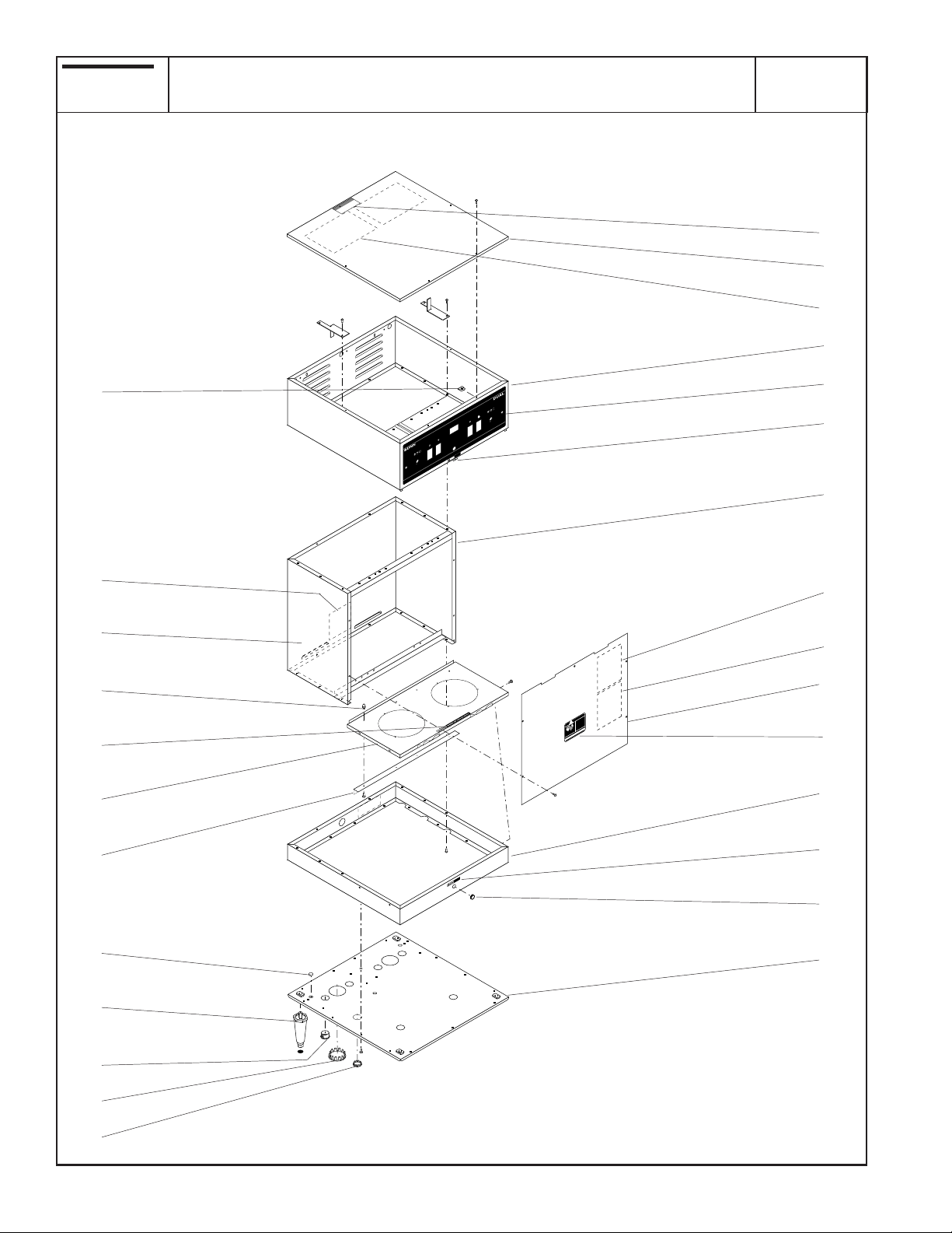
BASE - TRUNK - HOOD - COVERS & PANELS
ITEM PART NO. QTY. DESCRIPTION
1 25376.0000 1 Cover Assy, Top (Includes items 2 & 3)
02336.0000 4 Screw, Truss Head 4 - 40 x .38"
2 25151.0000 2 Shield, Insulator
3 10044.0000 1 Decal, Shut Off Power
4 22313.0000 1 Hood W/Decals (W/O Upper Faucet)
22313.0001 1 Hood W/Decals (W/O Upper Faucet & W/O Selector Switches)
22313.0002 1 Hood W/Decals (W/Upper Faucet & Selector Switches)
22313.0003 1 Hood W/Decals (W/Upper Faucet - W/O Selector Switches)
22313.0004 1 Hood W/Decals (W/Upper Faucet - W/one Grinder Interface)(Shown)
22313.0005 1 Hood W/Decals (W/O Upper Faucet - W/one Grinder Interface)
02308.0000 16 Screw, Pan Head 8 - 32 x .375"
5 20966.0000 1 Decal, Control Panel (W/O Upper Faucet)
20966.0001 1 Decal, Control Panel (W/O Upper Faucet & W/O Selector Switches)
20966.0002 1 Decal, Control Panel (W/Upper Faucet & Selector Switches)
20966.0003 1 Decal, Control Panel (W/Upper Faucet - W/O Selector Switches)
20966.0004 1 Decal, Control Panel (W/Upper Faucet - W/one Grinder Interface)(Shown)
20966.0005 1 Decal, Control Panel (W/O Upper Faucet - W/one Grinder Interface)
Includes items
5 &6
6 20201.5600 1 Decal, Caution Hot Water
7 24396.0000 1 Trunk W/Decals (120V)
24396.0001 1 Trunk W/Decals (120/240V, 200V & 230V)
8 00656.0000 1 Decal, Comply to Plumbing Code
9 00831.0000 1 Decal, Warning - Electrical
10 22314.0000 1 Panel W/Decals, Trunk (200V & 230V) (Includes items 11)
22314.0001 1 Panel W/Decals, Trunk (W/Mech. Thermostat)
22314.0002 1 Panel W/Decals, Trunk (W/Electronic Control)
22314.0003 1 Panel W/Decals, Trunk (W/Single Interface & Mech. Thermostat)
22314.0004 1 Panel W/Decals, Trunk (W/Single Interface & Electronic Control)
01382.0003 5 Screw, Truss Head 6 - 32 x .375"
11 00658.0000 1 Decal, Caution - Decanter/Funnel
12 10567.0000 1 Schematic (120V & 120/240V W/Mechanical Thermostat)
10567.0002 1 Schematic (120/240V W/Electronic Control)
10567.0004 1 Schematic (120V & 120/240V W/one Grinder Interface & Mechanical Thermostat)
10567.0005 1 Schematic (120/240V W/one Grinder Interface & Electronic Control)
13 24458.0000 1 Base W/Decal (Includes items 8,14 & 15)
02308.0000 8 Screw, Pan Head 8 - 32 x .375"
14 20201.5600 1 Decal, Caution Hot Water
Includes item 9
Includes items
11 & 12
15 00619.0007 1 Plug, Hole .50" Dia. (Not used W/Lower Faucet)
16 20916.0000 1 Cover, Bottom
02308.0000 12 Screw, Pan Head 8 - 32 x .375"
17 00619.0008 2 Plug, Hole 2.0" Dia.
18 03011.0000 6 Plug, Vent 1.0" Dia.
(continued)
5
10780 062100
BUNN
®
BASE - TRUNK - HOOD - COVERS & PANELS
DUAL
(continued)
E
C
!
OUR
L OR
S
E
NT
R
AN
NE
E
P
O
Y
OW
MP
P
WARNING
O
AN
F
C
!
ROM
L O
F
ANY
VA
F
CT
O
O
M
T
NE
N
EN
E RE
CO
EM
S
C
DI
FOR
E
B
PLA
RE
3
1
2
4
26
23
21
20
5
l
ga
2
⁄
1
1
al
1 g
gal
2
1⁄
DY
A
E
R
R
ER
I
R
GRIND
TO
G
EC
EL
S
H
T
L
E
R
E
M
R
F
A
/ W
T
N
O
T
R
TA
gal
1⁄2
1
al
1 g
gal
2
⁄
1
R
O
T
C
LE
E
S
Y
D
EA
R
S
R
E
T
A
T W
O
T
H
N
TAR
IO
S
T
U
A
C
!
R
E
RM
A
/ W
N
O
6
7
8
9
12
27
10
R
E
T
N
A
C
E
D
D
R
A
C
CAUTION
IS
D
!
:
IF
D
E
K
AC
ED
. CR
CH
T
TY
RA
P
RY
. SC
EM
E
EN
ILED D
M
H
LA
W
. BO
F
Y
R
RIC
IGH
U
N
J
ECT
N H
L
. HEATED
TIO
S
IN
O
T
RA
S
D E
N
K
E
SED
RPO
SE
IS
T
. U
CO
N
R
O
TIC
Y
A
L
C
R EXPO
-M
P
L
TS
-O
T
. O
M
E
NN
O
N
O
U
MEN
N
B
H
E
C
85
U
E
O
F
19
R
EL
T
E
R
U
A
IL
A
F
58
: 6
PN
11
13
22
24
19
18
17
25
14
HOT WATER
!
15
16
P-301
6
10780 032200

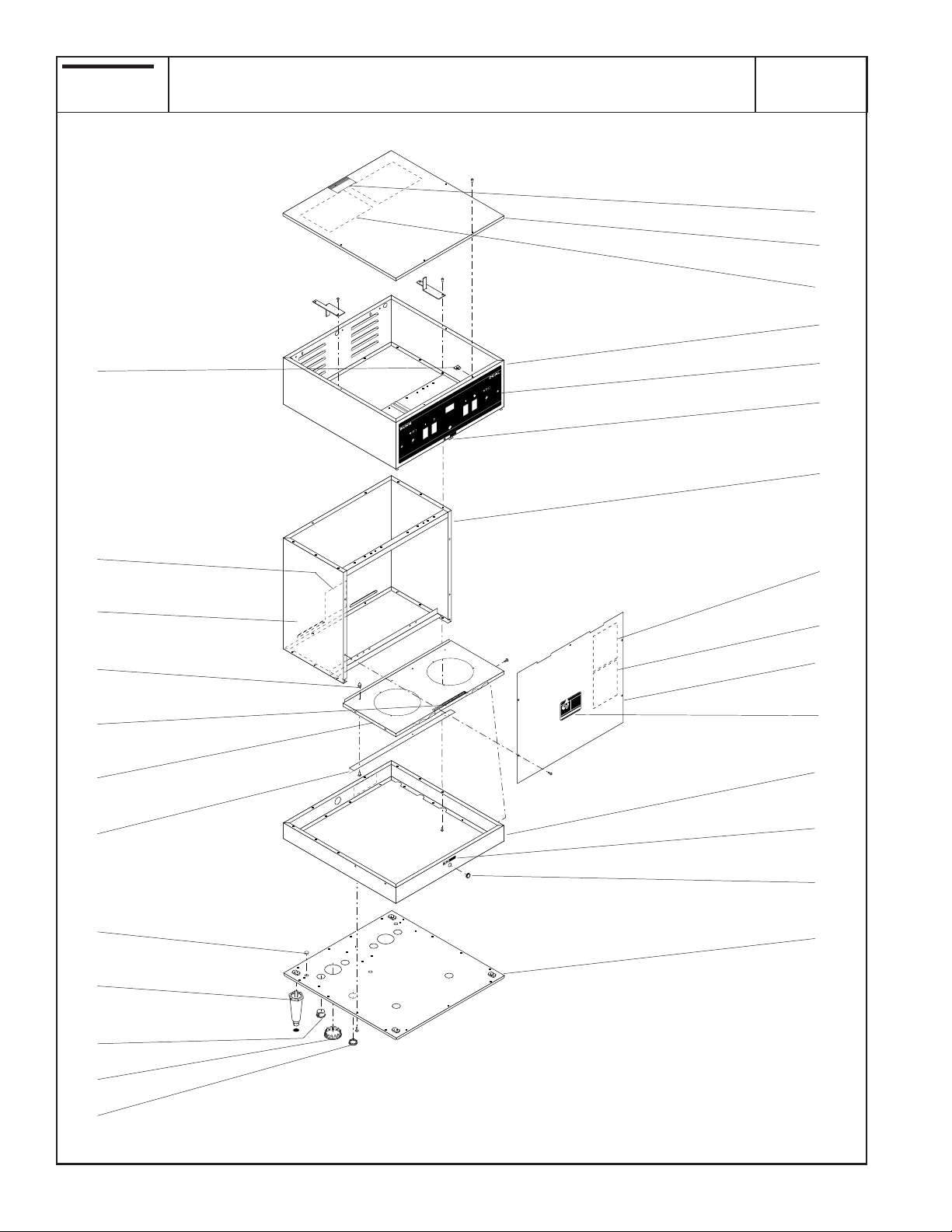
BASE - TRUNK - HOOD - COVERS & PANELS
ITEM PART NO. QTY. DESCRIPTION
19 03359.0000 4 Leg, 4.0" Plastic (Shown)
00502.0000 4 Leg, 4.0" Nickel
00506.0000 4 Leg, 8.0" SST
20 24455.0004 1 Warmer Panel Assy W/Decal (Includes items 21, 22, 23 & 01311.0000 Screws)
01382.0003 4 Screw, Truss Head 6 - 32 x .375"
21 12364.0000 1 Decal, Caution-Warmers are Hot
22 21106.0000 1 Angle, Support
01311.0000 4 Screw, Truss Head 8 - 32 x .25"
23 02324.0000 4 Nut, Acorn 8 - 32
24 00671.0000 2 Plug, Hole .312" Dia.
25 00619.0005 1 Plug, Hole 1.06" Dia.
26 00916.0000 4 Clip, J-Type #4-40
27 32540.0000 1 Decal, Timer Setting Instruction
7
10780 072805
BUNN
3
.
MINUTES
BUNN-O-MATIC
P/N 2620- 120 VAC
®
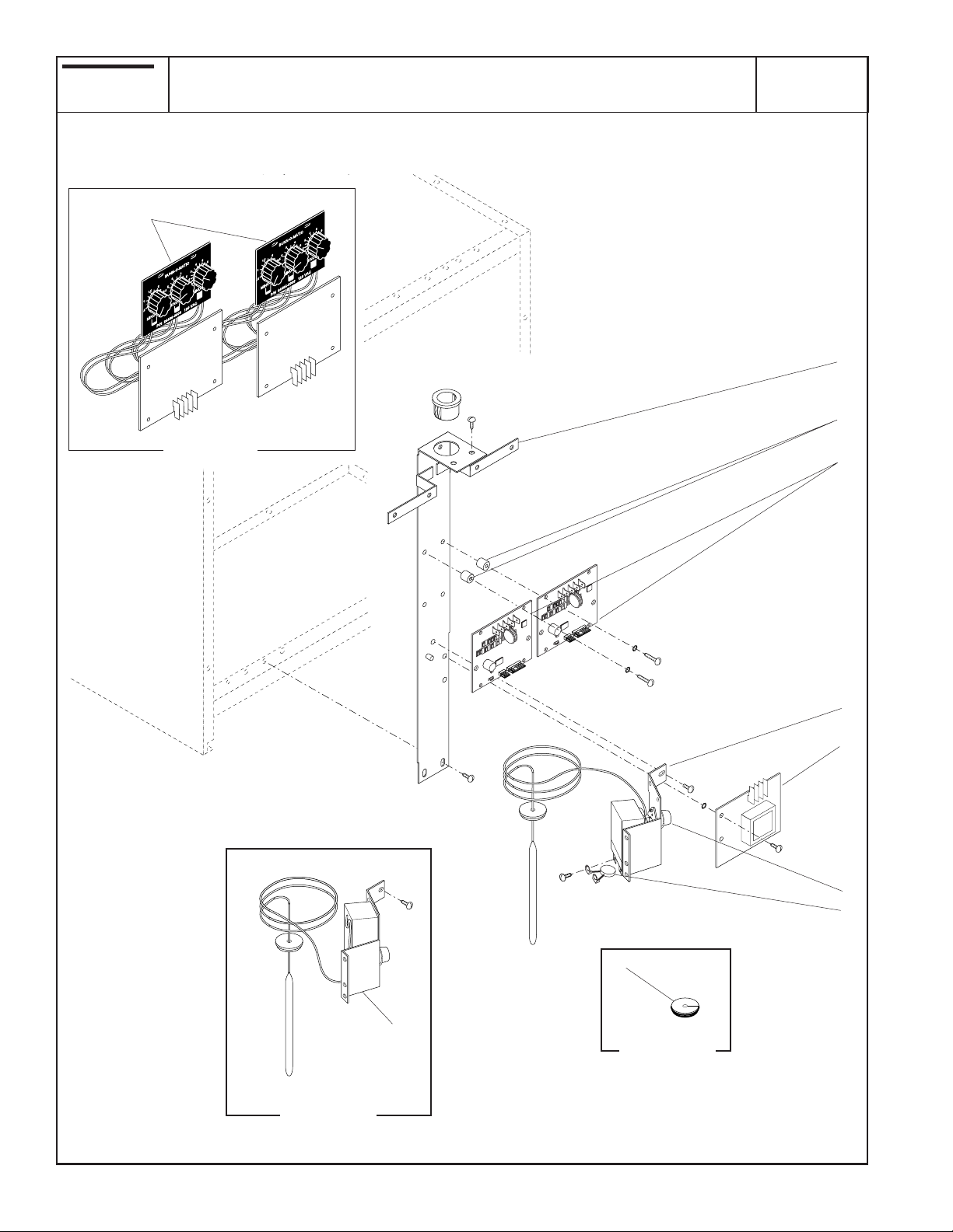
SINGLE SET TIMERS & MECHANICAL THERMOSTAT
.
MINUTES
BUNN-O-MATIC
P/N 2620- 120 VAC
DUAL
FIRST TYPE
1
2
3
TL5
TL4
TL3
TL2
TL1
TL5
TL4
TL3
TL2
TL1
J1
J2
SET
SET LOCK
LOCK
J1
J2
SET
SET LOCK
LOCK
4
6
Early Models
7
8
5
4
Replacement
Part
P-302
8
10780 062100

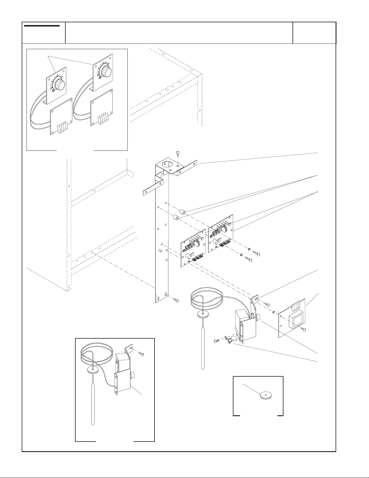
SINGLE SET TIMERS & MECHANICAL THERMOSTAT
ITEM PART NO. QTY. DESCRIPTION
1 20948.0001 1 Bracket, Component Mounting
02308.0000 4 Screw, Pan Head #8 - 32 x .375"
2 01533.0000 4 Spacer, Nylon .375"
3 02620.1040 2 Timer, 8 Min. 120V
02620.1041 2 Timer, 8 Min. 240V
32400.0002 2 Timer, Digital 120V
32400.0003 2 Timer, Digital 240V
01347.0000 4 Screw, Truss Head #6 - 32 x .375" (Not used with Digital Timer)
01510.0000 4 Lockwasher, External Tooth #6
01388.0000 4 Screw, Truss Head #6 - 32 x .75"
4 04314.0001 1 Thermostat Assy (Includes items 5,7 & 8)(Late Models)(Also replaces
early model thermostat)
02308.0000 1 Screw, Pan Head #8 - 32 x .375"
20762.0000 2 Screw, Binding Head #8-32 x .25" (Terminal Screw)
5 07073.0000 1 Grommet, Thermostat
6 07074.1026 1 Control Board, Level (120/208V & 120/240V models)
07074.1027 1 Control Board, Level (200V & 240V models)
02308.0000 2 Screw, Pan Head #8 - 32 x .375"
01511.0000 2 Lockwasher, External Tooth #8
7 00720.0000 1 Knob, Thermostat
8 28377.0000 1 Noise Suppressor (Not used with Digital Timer)
First Type
Second Type
9
10780 110501
BUNN
®
TRIPLE SET TIMERS & MECHANICAL THERMOSTAT
DUAL
3
1
2
FIRST TYPE
3
TL5
TL4
TL3
TL2
TL1
TL5
TL4
TL3
TL2
TL1
J1
J2
SET
SET LOCK
LOCK
J1
J2
SET
SET LOCK
LOCK
4
6
7
8
Early Models
5
4
Replacement
Part
P584
10
10780 062100

TRIPLE SET TIMERS & MECHANICAL THERMOSTAT
ITEM PART NO. QTY. DESCRIPTION
1 20948.0001 1 Bracket, Component Mounting
02308.0000 4 Screw, Pan Head 8 - 32 x .375"
2 01533.0000 4 Spacer, Nylon .375"
3 24486.1000 2 Timer, Triple (120/208V & 120/240V models)
24486.1001 2 Timer, Triple (200V - 240V)
32400.0002 2 Timer, Digital (120V)
32400.0003 2 Timer, Digital (240V)
01347.0000 4 Screw, Truss Head 6 - 32 x .375" (Not used with Digital Timer)
01510.0000 4 Lockwasher, External Tooth #6
01388.0000 4 Screw, Truss Head 6 - 32 x .75"
4 04314.0001 1 Thermostat Assy (Includes items 5,7 & 8)(Late Models)(Also replaces
early model thermostat)
02308.0000 1 Screw, Pan Head #8 - 32 x .375"
20762.0000 2 Screw, Binding Head #8-32 x .25" (Terminal Screw)
5 07073.0000 1 Grommet, Thermostat
6 07074.1026 1 Control Board, Level (120/208V & 120/240V models)
07074.1027 1 Control Board, Level (200V & 240V models)
02308.0000 2 Screw, Pan Head #8 - 32 x .375"
01511.0000 2 Lockwasher, External Tooth #8
7 00720.0000 1 Knob, Thermostat
8 28377.0000 1 Noise Suppressor (Not used with Digital Timer)
First Type
Second Type
11
10780 110501
BUNN
P/N 2620- 120 VAC
3
.
MINUTES
BUNN-O-MATIC
®
FIRST TYPE
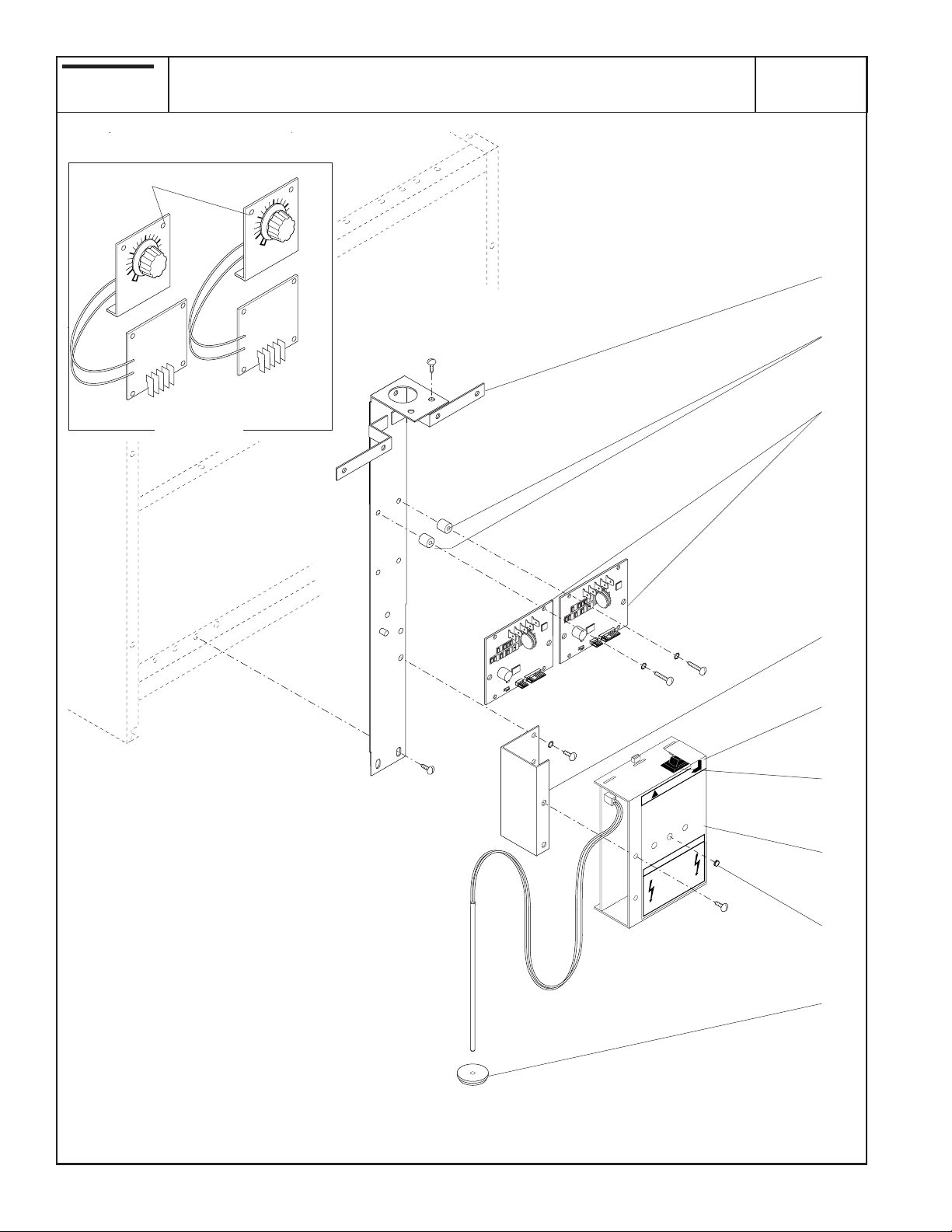
SINGLE SET TIMERS & ELECTRONIC CONTROL
.
MINUTES
BUNN-O-MATIC
P/N 2620- 120 VAC
DUAL
1
2
3
TL5
TL4
TL3
TL2
TL1
TL5
TL4
TL3
TL2
TL1
J1
J2
SET
SET LOCK
LOCK
J1
J2
SET
SET LOCK
LOCK
4
5
OFF
STOP
O
READ NOTICE
N
CAUTION
!
Water Tank Will Fill
Turn On The Tank Heater Switch
T
ater Comes From Opened Faucet!
DO NO
arranty!
Fill The Water Tank In
Until W
oids W
Hot Water Systems –
ply V
Automatically When Unit Is Connected To Power!
om
Coffee Brewers –
Accordance With The Installation Instructions!
Failure To C
WARNING
HAZARDOUS
VOLTAGE
DISCONNECT FROM
POWER SOURCE
BEFORE REMOVING!
6
7
8
9
12
P-303
10780 062100
 Loading...